EP3666976B1 - Artificial turf infill and artificial turf - Google Patents
Artificial turf infill and artificial turf Download PDFInfo
- Publication number
- EP3666976B1 EP3666976B1 EP18212783.7A EP18212783A EP3666976B1 EP 3666976 B1 EP3666976 B1 EP 3666976B1 EP 18212783 A EP18212783 A EP 18212783A EP 3666976 B1 EP3666976 B1 EP 3666976B1
- Authority
- EP
- European Patent Office
- Prior art keywords
- particles
- coating
- cork
- turf
- artificial turf
- Prior art date
- Legal status (The legal status is an assumption and is not a legal conclusion. Google has not performed a legal analysis and makes no representation as to the accuracy of the status listed.)
- Active
Links
Images


Classifications
-
- E—FIXED CONSTRUCTIONS
- E01—CONSTRUCTION OF ROADS, RAILWAYS, OR BRIDGES
- E01C—CONSTRUCTION OF, OR SURFACES FOR, ROADS, SPORTS GROUNDS, OR THE LIKE; MACHINES OR AUXILIARY TOOLS FOR CONSTRUCTION OR REPAIR
- E01C13/00—Pavings or foundations specially adapted for playgrounds or sports grounds; Drainage, irrigation or heating of sports grounds
- E01C13/08—Surfaces simulating grass ; Grass-grown sports grounds
Definitions
- the invention relates to artificial turf infill and an artificial turf with artificial turf infill.
- Artificial turf or artificial grass is a surface that is made up of fibers and is used to replace grass.
- the structure of the artificial turf is designed such that the artificial turf has an appearance that resembles grass.
- Artificial turf is typically used as a surface for sports such as soccer, American football, rugby, tennis and golf, or for playing fields or exercise fields. Furthermore, artificial turf is frequently used for landscaping applications.
- Artificial turf may be manufactured using techniques for manufacturing carpets. For example, artificial turf fibers, which have the appearance of grass blades, may be tufted or attached to a backing. Oftentimes, artificial turf infill is placed between the artificial turf fibers.
- Artificial turf infill is a granular material that covers the bottom portion of the artificial turf fibers.
- the use of artificial turf infill may have a number of advantages. For example, artificial turf infill may help the artificial turf fibers stand up straight. Artificial turf infill may also absorb impact from walking or running and provide an experience similar to being on real turf. The artificial turf infill may also help keep the artificial turf carpet flat and in place by weighing it down.
- rubber granulate or recycled (e.g. from car tires) rubber granulate is still most commonly used as artificial turf infill.
- the most commonly used rubber are styrene-butadiene rubber (SBR) or ethylene propylene diene monomer (EPDM), all of which can be generated from recycled rubber (post-consumer-waste or post-industrial-waste) or virgin material.
- SBR styrene-butadiene rubber
- EPDM ethylene propylene diene monomer
- Recycled rubbers are cost effective products as they are derived from existing products that have reached the end of their service life.
- US4337283 discloses the use of a mixture of granules of two or more different resilient materials as the resilient particle components of a turf infill.
- a mixture of cork granules and rubber particles formed by shedding rubber tire stock with fine sand is disclosed therein as making an excellent top-dressing.
- cork has the tendency to float away during heavy rainfall or be blown away by wind.
- the invention provides for an improved turf infill and an artificial turf with the improved turf infill.
- a turf infill as defined by independent claim 1.
- Further advantageous features of the invention are defined by embodiments of the invention as defined by the dependent claims. The problem is solved by the features as specified in the independent claim.
- the weight percentage ratio of the cork particles to the rubber particles is between 1 : 4 and 1 : 8. This proportion of weight percentage is beneficial, as the bulk density and/or poured density (freely settled bulk density) of the cork particles is much lighter than the bulk density and/or poured density of the rubber particles. Therefore, in order to obtain an optimal weight distribution of cork particles and rubber particles, the weight percentage ratio is chosen to be between 1 : 4 and 1 : 8.
- this weight ratio provides that the size and the surface areas of both the cork and rubber particles is within the same range, thus the friction resistance between the cork particles and rubber particles is basically homogenous .
- particles of cork and rubber may be of any suitable shape, including granules, gravel, grains and combinations thereof, and in various dimensions thereof.
- the coating may be applied to the cork particles and rubber particles using any suitable method, and such methods are well known in the art.
- the cork particles may be coated, e.g. in a flow reactor or batch reactor, separately from the rubber particles or both (rubber particles and cork particles) may be coated simultaneously, e.g. in the same flow reactor or batch reactor. Methods for coating the particles are disclosed for example in WO 2017/153261 .
- polyurethane PU
- PVB polyvinyl butyral
- acrylic resin acrylic resin
- methacrylates methacrylates
- methyl acrylates methacrylates
- cork particles as part of the mixture of the inventive turf infill may be beneficial, as cork is a renewable raw material derived from the bark of the cork oak (Quercus suber) from sustainably managed sources, and the particles can also be recycled from leftover material, e.g. from bottle cork production.
- cork is not known to have any environmental toxicity, has insulating properties with low heat absorption when exposed to sunlight and has elastic features.
- cork particles as part of the mixture of the inventive turf infill may be beneficial, even though the U.V. resistance and the mechanical stability/resistance are limited.
- the coating of the cork particles may be beneficial, as the coating may weigh down the relatively light cork particles. This can reduce the tendency of cork to float away during heavy rainfall or be blown away by wind and may reduce the unmixing of particles of different weight.
- the coating can comprise one or more layers. The layers can have the same or different thickness. The polymer and/or resin component of the layers of the coating may be the same or different.
- coating may have the effect that coated cork particles cling together or are honed by friction during particle movement and the abrasion and wear is thus reduced, and the mechanical stability may be increased.
- the coating of the known rubber particles may be beneficial, as the coating may prevent the possibly health-affecting substances to be released from the rubber particles.
- rubber particles recycled even from car tires, e.g. in the shape of granules can be used for the inventive infill material.
- the coating can comprise one or more layers.
- the layers can have the same or different thickness.
- the polymer and/or resin component of the layers of the coating may be the same or different.
- cork particles and rubber particles may be beneficial in many aspects, as both cork particles and rubber particles can be recycled from previously manufactured materials, e.g. rubber particles from car tires and cork particles from e.g. leftover material from bottle cork production.
- cork is a renewable raw material.
- the heating up of the artificial turf to high temperatures i.e., to temperatures well above the ambient temperature
- the heating up of rubber particles may be reduced due to the insulating properties of cork particles.
- the coating of the cork particles and the rubber particles which may, e.g., have a higher coefficient of friction than rubber or cork and/or may be slightly sticky, may slow the segregation (unmixing) over time due to different weights or sizes.
- the weight percentage ratio can be chosen to be between 1 : 5.5 and 1 : 6.5. Due to this optimized weight percentage ration, it may also be possible to achieve that the optical perception of the particles is homogeneous.
- the polymer and/or resin component of the coating of the cork particles and/or rubber particles is polyurethane (PU).
- a polyurethane coating may be beneficial as fully reacted polyurethane polymer is considered to be chemically inert and thus environmental friendly and may be produced as a hard, abrasion-resistant, and durable coating, which may seal the rubber granule.
- the polymer and/or resin component of the coating of the cork particles and/or rubber particles is polyvinyl butyral (PVB).
- PVB is a resin, which can be prepared from polyvinyl alcohol by reaction with butyraldehyde, and can be acquired from remnants during production of laminated glass or can be recycled from laminated glass. PVB may be used as a protective layer around the particles. In addition, PVB has good adhesion to rubber and cork, may be sticky, and is tough and flexible.
- the coating of the cork particles comprises fillers, in particular barium sulphate (barite), calcium carbonate (chalk), talc, quartz silica, other silicates, other oxides (such as iron oxides), hydro oxides, hollow glass spheres, organic fillers or a combination thereof.
- fillers in particular barium sulphate (barite), calcium carbonate (chalk), talc, quartz silica, other silicates, other oxides (such as iron oxides), hydro oxides, hollow glass spheres, organic fillers or a combination thereof.
- fillers can be advantageous, as the fillers are able to increase the weight of the coating and may thus increase the overall poured density of the coated cork particles. Thus, as the weight of the coated particles increases, the risk of coated cork floating away during heavy rainfall or being blown away by strong wind is further reduced.
- the coating may comprise between 0.1 wt.% to 60 wt.% of fillers.
- the coating of the cork particles comprises barium sulphate (barite) and/or calcium carbonate (chalk) as fillers, to increase the total weight of the artificial turf infill.
- barite barium sulphate
- chalk calcium carbonate
- Barium sulphate (barite) and calcium carbonate (chalk) are particular advantageous, as they have a high density, e.g. calcium carbonate has a density of 2.7 g/cm 3 and barium sulphate has a density between 4.0 and 4.5 g/cm 3 , are relatively cheap materials and may be used to provide a dense coating.
- the coating of the cork particles and/or rubber particles comprises particles selected from the group consisting of colored pigments, copper(II) sulfate particles, silver particles, chitosan particles or mixtures thereof.
- the colored pigments may be inorganic, such as, e.g., iron oxide pigments, chromium oxide pigments and/or cobalt oxide pigments, or organic pigments. Further, the colored pigments may be infrared-reflective pigments, which are beneficial due to their ability to reflect infrared light. This may reduce the heating of the artificial turf infill. Further, as the infrared-reflective colored pigments may be contained solely in the applied coating, the costs for the comparably expensive and precious pigments, being merely on the surface of the cork particles and/or rubber particles, is reduced.
- Copper(II) sulfate particles and/or chrome particles and/or iron oxide particles may be further beneficial due to their color, relatively low manufacturing costs and/or antibacterial properties.
- Other antibacterial components that may be used are silver and/or chitosan particles, both of which have natural antibacterial properties.
- the overall layer thickness of the coating of the cork particles and/or rubber particles is between 0.1 ⁇ m and 1 mm, or between 0.5 ⁇ m to 750 ⁇ m, or between10 ⁇ m to 150 ⁇ m.
- the coating of the cork particles and/or rubber particles may each comprise one or more (sub-)layers.
- the (sub-)layers may have the same or different thicknesses, however, the sum of the individual layer thicknesses is between 0.1 ⁇ m and 1 mm.
- the overall layer thickness of the coating of the cork particles and/or rubber particles is between 10 ⁇ m and 150 ⁇ m.
- the particles can be coated with one layer or with more layers. To increase the likelihood that that the particles are fully encapsulated and thus no possibly health-affecting substances may be released, it may be beneficial to coat the particles two or more times.
- the size of the coated cork particles is between any one of the following: 0.03 mm and 3.5 mm, and 0.3 mm and 2.5 mm; and the size of the coated rubber particles is between any one of the following: 0.03 mm and 3.5 mm, and 0.3 mm and 2.5 mm
- This configuration allows for a well-adjusted particle size distribution for artificial turf. Furthermore, the (natural) particle size distribution within each range allows the particles to be packed more densely.
- the turf infill further comprises microporous zeolite mineral particles.
- the microporous zeolite mineral particles have pores that form openings on the outer surface of the microporous zeolite mineral particles.
- the use of the microporous zeolite mineral as an infill material is advantageous, as the particles are able to regulate the presence of water and may thus provide for a cooling effect of the surface of the artificial turf. Hence, an increased playing comfort can be reached when the outside temperatures are high.
- the microporous zeolite mineral particle may be selected from the group consisting of chabazite, erionite, mordenite, clinoptilolite, faujasite, phillipsite, zeolite A, zeolite L, zeolite Y, zeolite X and ZSM-5.
- the zeolite used may thus be a zeolite that can be natural or obtained by synthesis.
- a microporous zeolite with a Mohs hardness above 3 and/or a strong absorbent power and/or a color that approximately resembles one of the well-known surface colors (e.g., red, brown, green), may preferably be used.
- the most preferred microporous zeolite mineral may be of the chabazite and/or clinoptinolite and/or mordenite type.
- the particle size of the microporous zeolite mineral particles is between any one of the following: 0.5 mm and 3.5 mm and 1.0 mm and 2.5 mm, and the weight percentage ratio of the microporous zeolite mineral particles to the cork particles and the rubber particles is between 2 : 7 and 4 : 7, in particular between 2.5 : 7 and 3.5 : 7.
- microporous zeolite mineral particles it may be envisaged that the outer surface of at least some microporous zeolite mineral particles is partly covered with a polyurethane coating.
- a polyurethane coating it may be feasible that 75 % to 99 % of the outer surface of a microporous zeolite mineral particle is partly covered with a polyurethane coating.
- the partial covering is applied on each side of each microporous zeolite mineral particle, but that there are gaps (holes) in the covering enclosing the particles.
- the partial coating is advantageous, since water can be absorbed and/or released by the microporous zeolite mineral particles through the pores contained in its surface areas, which are not covered by the polyurethane coating.
- the microporous zeolite mineral particles are partly coated with the polyurethane coating, natural occurrence of abrasion and wear of the microporous zeolite mineral during use may be reduced, since the polyurethane coating may provide for a harder and thus protective surface compared to uncoated microporous zeolite mineral particles.
- the Mohs hardness of polyurethane coating can be chosen to be higher or much higher than the Mohs hardness of the microporous zeolite mineral particles. It may be thus beneficial that the Mohs hardness of the polyurethane coating is at least one Mohs unit higher than the Mohs hardness of the selected microporous zeolite mineral particles.
- the gaps in the coating of the inventive infill material may result during the manufacture of the infill material, as during the mixing, e.g. in a flow reactor or a batch reactor or a tumbler, the microporous zeolite mineral particles and a liquid polyurethane reaction mixture are mixed and while they are being mixed a solidification reaction is initiated.
- the microporous zeolite mineral particles physically touch and interact with each other, thereby causing collision defects (e.g. gaps) in the coating and partly leaving the surface of the microporous zeolite particles uncovered.
- collision defects e.g. gaps
- the polyurethane coating extends over some of the pores forming respective covers of the pore openings, wherein the polyurethane coating coats a portion of the inner surface of the covered pores in the region of the cover.
- the coating may penetrate a slight distance, for example between 0.2 ⁇ m and 500 ⁇ m, preferably between 1 and 150 ⁇ m and most preferred between 10 ⁇ m and 100 ⁇ m into the surface pores and thus may interfere with the pores in a form-locking manner.
- the hold of the coating on the microporous zeolite mineral particles may be increased and at the same time the overall stability and hardness of the microporous zeolite mineral particles may be increased.
- the infill material is preferably produced by mixing the microporous zeolite mineral particles with a liquid polyurethane reaction mixture and initializing the solidification reaction during the mixing, the microporous zeolite mineral particles have the same amount of their outer surface covered by the coating relative to the total outer surface. Substantially the same amount means that the outer surface of each of the partly coated microporous zeolite mineral particle is coated between 20 % and 99 %, preferably between 50 % to 98 % or between 70% to 99 %, with the polyurethane coating. Further, since the outer surface of each of the partly coated microporous zeolite mineral particle is - with the exception of the gaps - essentially fully coated, fine dusts may be bound.
- the polyurethane coating of the microporous zeolite mineral particles may be based on a liquid polyurethane reaction mixture, which may be a dispersion or solution, comprising
- liquid polyurethane reaction mixture may be advantageous, because it is a reaction mixture that can be solidified or cured (e.g., by cross-linking) under heat and/or by adding water. Therefore, the zeolite mineral particles and the liquid polyurethane reaction mixture may be mixed and solidified simultaneously in a batch reactor, a continuous reactor or a tumbler, resulting in the partial polyurethane coating or the coating with gaps. Further, the resulting polyurethane coating may be a waterborne polyurethane coating.
- the polyurethane coating of the microporous zeolite mineral particles may be based on a liquid polyurethane reaction mixture comprising:
- liquid polyurethane reaction mixture may be advantageous, because it is a reaction mixture that can be solidified or cured (e.g., by cross-linking) by adding a catalyst, e.g. a secondary amine catalyst, a tertiary amine catalyst, such as triethylenediamine or e.g.1,4-Diazabicyclo[2.2.2]octane, cyclic amines such as 1,8-Diazabicyclo(5.4.0)undec-7-ene (DBU) or a metal organic catalyst, and water. Therefore, the zeolite mineral particles and the liquid polyurethane reaction mixture may be mixed and solidified simultaneously in a controlled manner in a batch or continuous reactor, resulting in the partial polyurethane coating or the coating with holes.
- a catalyst e.g. a secondary amine catalyst, a tertiary amine catalyst, such as triethylenediamine or e.g.1,4-Diazabicyclo[2.2.2]octane, cycl
- the polyurethane coating of the microporous zeolite mineral particles may further comprise a rheology additive that is adapted to induce a thixotropic flow behavior in one of the above described liquid polyurethane reaction mixtures.
- Adding a rheology additive with thixotropic capabilities may be advantageous in order to achieve a controllable viscosity-increasing thixotropic flow behavior of the (e.g., liquid or fluid) polyurethane coating while applying it, e.g. by mixing the liquid polyurethane reaction mixture with the microporous zeolite mineral particles, to the surface of the microporous zeolite mineral particles in order to control or reduce the depth of penetration of the liquid polyurethane reaction mixture into the pores contained in the surfaces of the microporous zeolite mineral particles.
- the (e.g., liquid or fluid) polyurethane coating e.g., liquid or fluid) polyurethane coating while applying it, e.g. by mixing the liquid polyurethane reaction mixture with the microporous zeolite mineral particles, to the surface of the microporous zeolite mineral particles in order to control or reduce the depth of penetration of the liquid polyurethane reaction mixture into the pores contained in the surfaces
- Suitable rheology additives may be e.g. fumed silica (e.g. synthetic, hydrophobic, amorphous silica), also known as pyrogenic silica, made from flame pyrolysis of silicon tetrachloride or from quartz sand vaporized in a 3000 °C electric arc, hydrophobic fumed silica, bentonite, acrylates or a combination of the aforementioned additives.
- fumed silica e.g. synthetic, hydrophobic, amorphous silica
- pyrogenic silica made from flame pyrolysis of silicon tetrachloride or from quartz sand vaporized in a 3000 °C electric arc
- hydrophobic fumed silica bentonite
- acrylates or a combination of the aforementioned additives.
- microporous zeolite mineral particles are charged with a salt solution.
- Microporous zeolite mineral particles charged with salt ions may allow for an increased water adsorption and/or water desorption effect.
- microporous zeolite mineral particles allows a synergy to operate between the following properties: the adsorption, absorption and release of water of the microporous zeolite mineral particles, and the ability to lower the freezing temperature of the water.
- the microporous mineral particle in the presence of humidity, is in a position to adsorb and/or absorb this humidity in order to prevent, on the one hand, the surface formation of a layer of slippery frost, in the case of a negative temperature, and on the other hand, the agglomeration of the turf infills.
- the coated rubber and coated cork particles in combination with the microporous mineral particles, which are loaded with salt and water may further allow a further increased release of the water and the maintenance of relative humidity at the surface of said turf.
- the microporous mineral loaded with salt adsorbs and/or absorbs the water and then continuously releases those water molecules by desorption. This continuous release of the water by the microporous mineral avoids rapid evaporation of the water after watering the surface and allows a lower temperature to be maintained at the level of the field surface compared to the ambient temperature. Said microporous mineral loaded with salt thus further reduces the amount of watering usually necessary to refresh a turf surface.
- the invention relates to turf infill, as described above, for an artificial turf comprising an artificial turf carpet, wherein the artificial turf carpet comprises multiple artificial turf fiber tufts, and wherein the turf infill is configured for scattering between the multiple artificial turf fiber tufts of the artificial turf.
- the invention relates to an artificial turf, wherein the artificial turf comprises an artificial turf carpet, wherein the artificial turf carpet comprises multiple artificial turf fiber tufts, and a turf infill, as described above, which is scattered between the multiple artificial turf fiber tufts.
- an artificial turf 600 with artificial turf carpet 500 is shown.
- the artificial turf carpet 500 contains a backing 502.
- the artificial turf carpet 500 is a tufted artificial turf carpet, which is formed by artificial turf fiber tufts 504 that are tufted into the backing 502.
- the artificial turf fiber tufts 504 are tufted in rows. There is row spacing 506 between adjacent rows of tufts.
- the artificial turf fiber tufts 504 also extend a distance above the backing 502. The distance that the fibers 504 extend above the backing 502 is the pile height 508.
- the artificial turf carpet 500 has been installed by placing or attaching it to the ground 510 or a floor.
- the turf infill 100 has been spread out on the surface and distributed between the artificial turf fiber tufts 504.
- the turf infill 100 comprises coated cork particles (here granules) and coated rubber particles (here granules).
- Fig. 2 a detail from Fig. 1 is shown to visualize the turf infill comprising cork particles 200, wherein the cork particles 200 are coated with a polymer and/or resin component, and rubber particles 300, wherein the rubber particles 300 are coated with a polymer and/or resin component.
- the cork granules 200 and the rubber granules 300 both have a coating, which may, e.g., have a higher coefficient of friction than rubber or cork by themselves or may be slightly sticky.
- the coating may slow the segregation (unmixing) over time due to different weights or sizes of the different granules.
- the weight percentage ratio can be chosen to be between 1 : 4 and 1 : 8.
- the coating 202 of the cork particles 200 is manufactured from a polymer and/or resin component, which may be polyurethane (PU) or polyvinyl butyral (PVB).
- the coating 302 of the rubber particles 300 is also manufactured from a polymer and/or resin component, which may be polyurethane (PU) or polyvinyl butyral (PVB).
- Fig. 4 depicts the coated cork particles 200 and the coated rubber particles 300 of the turf infill.
- the coating 202 of the cork particles 200 comprises fillers, here barium sulphate particles 204 and calcium carbonate particles 205. It shall be understood, that it is also feasible that either only barium sulphate particles 204 or only calcium carbonate particles 205 may be used as fillers. The use of both described fillers can be advantageous, as these fillers are able to increase the weight of the coating 202 and may thus increase the overall poured density of the coated cork particles 200.
- the coating 302 of the rubber particles 300 is comprised of two layers, an inner layer 302a and an outer layer 302b. The double-layer coating may prevent possibly health-affecting substances to be released from the rubber particles 300.
- Fig. 5 depicts the turf infill 100 comprising microporous zeolite minerals 400, cork particles 200, wherein the cork particles 200 are coated with a polymer and/or resin component, and rubber particles 300, wherein the rubber particles 300 are coated with a polymer and/or resin component.
- the microporous zeolite minerals 400 may be uncoated microporous zeolite minerals 400 or partially coated microporous zeolite minerals 400 as depicted in Figures 6 to 8 .
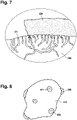
- Fig. 6 shows a microporous zeolite mineral particle after it has been partially coated with a polyurethane coating 420 and may thus be used as part of an infill material. As can be seen, at least some parts of the surface of the coated microporous zeolite mineral particle 400 are not covered by the polyurethane coating 420. In Fig. 6 a dotted circle is also indicated, the schematic content of which is enlarged in Fig. 7 .
- the microporous zeolite mineral particle 400 which contains pores 411, has been partially coated with a polyurethane coating 420.
- the polyurethane coating 420 was formed by providing microporous zeolite mineral particles 400 and a liquid polyurethane reaction mixture in a batch reactor, tumbler or continuous reactor. Simultaneous mixing and initialization of the solidification reaction lead to the desired partial coating of the polyurethane coating 420 on the surface of the microporous zeolite mineral particle 400.
- the partial coating results from microporous zeolite mineral particles 400 colliding while being mixed with the initialized liquid polyurethane reaction mixture.
- the polyurethane coating 420 coats a portion of the inner surface of the microporous zeolite mineral particle 400 in the region of the cover.
- the coating 420 may penetrate with a slight distance, for example between 0.2 ⁇ m and 500 ⁇ m, preferably between 1 and 150 ⁇ m and most preferred between 10 ⁇ m and 100 ⁇ m into the surface pores 411 and thus may interfere with the pores 411 in a form-locking manner.
- the hold of the coating on the microporous zeolite mineral particle 400 may be increased and at the same time the overall stability and hardness of the microporous zeolite mineral particle 400 may be increased.
- the partially coated microporous zeolite mineral particle 400 is preferably produced by mixing the microporous zeolite mineral particles with a liquid polyurethane reaction mixture and initializing the solidification reaction during the mixing, the microporous zeolite mineral particles have substantially the same amount of their outer surface covered by the coating relative to the total outer surface.
- each microporous zeolite mineral particle is covered between 20 % and 99 %, preferably between 50 % to 98 % or between 70% to 99 %, with the polyurethane coating 420. Since the outer surface of each microporous zeolite mineral particle 400 is - with the exception of the gaps - essentially fully coated, fine dusts may be bound.
- the polyurethane coating 420 may comprise a rheology additive. The rheology additive may be added in order to achieve thixotropic flow behavior of the liquid polyurethane reaction mixture during mixing of the liquid polyurethane reaction mixture with the microporous zeolite mineral particle 400.
- Fig. 8 depicts a partly coated microporous zeolite mineral particle 400.
- the microporous zeolite mineral particle 400 has pores 411 that form openings on the outer surface of the microporous zeolite mineral particles 400.
- the outer surface of the microporous zeolite mineral particles 400 is partly coated with a polyurethane coating 420, wherein the coating extends over most of the pores 411, thereby forming respective covers of the openings.
- the polyurethane coating 420 was formed by providing a plurality of microporous zeolite minerals particles 400 and a liquid polyurethane reaction mixture in a batch reactor, tumbler or continuous reactor.
- Simultaneous mixing and initialization of the solidification reaction lead to the desired partial coating of the polyurethane coating 420 on the surface of the microporous zeolite mineral particle 400.
- the partial coating results from collisions of microporous zeolite mineral particles 400 while being mixed with the initialized liquid polyurethane reaction mixture. Since the initialization of the solidification reaction takes place simultaneously, uncovered spaces (e.g., gaps or holes), created by collisions, remain on the surface of the microporous zeolite mineral particles. As indicated in Fig. 8 , it may be feasible that 75 % to 99 % of the outer surface of the microporous zeolite mineral particle is partly covered with a polyurethane coating 420.
Landscapes
- Engineering & Computer Science (AREA)
- Architecture (AREA)
- Civil Engineering (AREA)
- Structural Engineering (AREA)
- Road Paving Structures (AREA)
Description
- The invention relates to artificial turf infill and an artificial turf with artificial turf infill.
- Artificial turf or artificial grass is a surface that is made up of fibers and is used to replace grass. The structure of the artificial turf is designed such that the artificial turf has an appearance that resembles grass. Artificial turf is typically used as a surface for sports such as soccer, American football, rugby, tennis and golf, or for playing fields or exercise fields. Furthermore, artificial turf is frequently used for landscaping applications.
- Artificial turf may be manufactured using techniques for manufacturing carpets. For example, artificial turf fibers, which have the appearance of grass blades, may be tufted or attached to a backing. Oftentimes, artificial turf infill is placed between the artificial turf fibers.
- Artificial turf infill is a granular material that covers the bottom portion of the artificial turf fibers. The use of artificial turf infill may have a number of advantages. For example, artificial turf infill may help the artificial turf fibers stand up straight. Artificial turf infill may also absorb impact from walking or running and provide an experience similar to being on real turf. The artificial turf infill may also help keep the artificial turf carpet flat and in place by weighing it down.
- Even though the artificial turf infills known from the art are being constantly further developed, rubber granulate or recycled (e.g. from car tires) rubber granulate is still most commonly used as artificial turf infill. The most commonly used rubber are styrene-butadiene rubber (SBR) or ethylene propylene diene monomer (EPDM), all of which can be generated from recycled rubber (post-consumer-waste or post-industrial-waste) or virgin material. Recycled rubbers are cost effective products as they are derived from existing products that have reached the end of their service life. Even though recycling of, e.g., used car tires to artificial turf infill particles has an environmentally friendly aspect, concerns of potential health effects of synthetic turf sports fields with vulcanized (either by peroxide or sulphur vulcanization) recycled rubber infill have lately arisen due to the fear that numerous health affecting substances might be released from the granulate. Another negative side effect of the use of rubber as artificial turf infill is that in the hot season, when the outside surfaces are subjected to severe heat, rubber based artificial turf infill materials tend to heat to temperatures up to 20-40 °C above the ambient temperature.
-
US4337283 discloses the use of a mixture of granules of two or more different resilient materials as the resilient particle components of a turf infill. A mixture of cork granules and rubber particles formed by shedding rubber tire stock with fine sand is disclosed therein as making an excellent top-dressing. However, cork has the tendency to float away during heavy rainfall or be blown away by wind. - It is therefore the purpose of the invention to provide an improved turf infill material, which is environmentally friendly, is less likely to release potentially health-affecting substances and has an optimal weight distribution of the particles.
- The invention provides for an improved turf infill and an artificial turf with the improved turf infill. According to the invention, there is provided a turf infill as defined by independent claim 1. Further advantageous features of the invention are defined by embodiments of the invention as defined by the dependent claims. The problem is solved by the features as specified in the independent claim.
- According to the invention, the weight percentage ratio of the cork particles to the rubber particles is between 1 : 4 and 1 : 8. This proportion of weight percentage is beneficial, as the bulk density and/or poured density (freely settled bulk density) of the cork particles is much lighter than the bulk density and/or poured density of the rubber particles. Therefore, in order to obtain an optimal weight distribution of cork particles and rubber particles, the weight percentage ratio is chosen to be between 1 : 4 and 1 : 8.
- According to the invention, this weight ratio provides that the size and the surface areas of both the cork and rubber particles is within the same range, thus the friction resistance between the cork particles and rubber particles is basically homogenous .
- In one embodiment, particles of cork and rubber may be of any suitable shape, including granules, gravel, grains and combinations thereof, and in various dimensions thereof.
- The coating may be applied to the cork particles and rubber particles using any suitable method, and such methods are well known in the art. The cork particles may be coated, e.g. in a flow reactor or batch reactor, separately from the rubber particles or both (rubber particles and cork particles) may be coated simultaneously, e.g. in the same flow reactor or batch reactor. Methods for coating the particles are disclosed for example in
WO 2017/153261 . - It is intended that the polymer and/or resin component of the coatings does not show any environmental toxicity. Possible polymer and/or resin components are selected from the group consisting of polyurethane (PU), polyvinyl butyral (PVB), acrylic resin, acrylate monomers, methacrylates, methyl acrylates and blends thereof.
- The use of cork particles as part of the mixture of the inventive turf infill may be beneficial, as cork is a renewable raw material derived from the bark of the cork oak (Quercus suber) from sustainably managed sources, and the particles can also be recycled from leftover material, e.g. from bottle cork production. Furthermore, cork is not known to have any environmental toxicity, has insulating properties with low heat absorption when exposed to sunlight and has elastic features. Hence cork particles as part of the mixture of the inventive turf infill may be beneficial, even though the U.V. resistance and the mechanical stability/resistance are limited.
- The coating of the cork particles may be beneficial, as the coating may weigh down the relatively light cork particles. This can reduce the tendency of cork to float away during heavy rainfall or be blown away by wind and may reduce the unmixing of particles of different weight. The coating can comprise one or more layers. The layers can have the same or different thickness. The polymer and/or resin component of the layers of the coating may be the same or different. In addition, coating may have the effect that coated cork particles cling together or are honed by friction during particle movement and the abrasion and wear is thus reduced, and the mechanical stability may be increased.
- The coating of the known rubber particles may be beneficial, as the coating may prevent the possibly health-affecting substances to be released from the rubber particles. Hence, rubber particles recycled even from car tires, e.g. in the shape of granules, can be used for the inventive infill material. The coating can comprise one or more layers. The layers can have the same or different thickness. The polymer and/or resin component of the layers of the coating may be the same or different.
- The combination of cork particles and rubber particles may be beneficial in many aspects, as both cork particles and rubber particles can be recycled from previously manufactured materials, e.g. rubber particles from car tires and cork particles from e.g. leftover material from bottle cork production. In addition, cork is a renewable raw material. Furthermore, the heating up of the artificial turf to high temperatures (i.e., to temperatures well above the ambient temperature), caused by the heating up of rubber particles, may be reduced due to the insulating properties of cork particles. Further, the coating of the cork particles and the rubber particles, which may, e.g., have a higher coefficient of friction than rubber or cork and/or may be slightly sticky, may slow the segregation (unmixing) over time due to different weights or sizes.
- In order to obtain an approximately even number of cork particles and rubber particles, the weight percentage ratio can be chosen to be between 1 : 5.5 and 1 : 6.5. Due to this optimized weight percentage ration, it may also be possible to achieve that the optical perception of the particles is homogeneous.
- According to one embodiment it is envisaged that the infill is configured such that the
- poured density of the coated cork particles is between any one of the following: 90 g/dm3 and 180 g/dm3 , 100 g/dm3 and 150 g/dm3 , and 125 g/dm3 and 135 g/dm3 ; and the
- poured density of the coated rubber particles is between any one of the following: 400 g/dm3 and 650 g/dm3 , 450 g/dm3 and 600 g/dm3 , and 530 g/dm3 and 550 g/dm3 .
- In one embodiment of the invention the polymer and/or resin component of the coating of the cork particles and/or rubber particles is polyurethane (PU).
- A polyurethane coating may be beneficial as fully reacted polyurethane polymer is considered to be chemically inert and thus environmental friendly and may be produced as a hard, abrasion-resistant, and durable coating, which may seal the rubber granule.
- Alternatively, the polymer and/or resin component of the coating of the cork particles and/or rubber particles is polyvinyl butyral (PVB).
- The use of PVB as a coating may be beneficial, as PVB is a resin, which can be prepared from polyvinyl alcohol by reaction with butyraldehyde, and can be acquired from remnants during production of laminated glass or can be recycled from laminated glass. PVB may be used as a protective layer around the particles. In addition, PVB has good adhesion to rubber and cork, may be sticky, and is tough and flexible.
- In on embodiment of the invention, the coating of the cork particles comprises fillers, in particular barium sulphate (barite), calcium carbonate (chalk), talc, quartz silica, other silicates, other oxides (such as iron oxides), hydro oxides, hollow glass spheres, organic fillers or a combination thereof.
- The use of fillers can be advantageous, as the fillers are able to increase the weight of the coating and may thus increase the overall poured density of the coated cork particles. Thus, as the weight of the coated particles increases, the risk of coated cork floating away during heavy rainfall or being blown away by strong wind is further reduced. In is envisaged that the coating may comprise between 0.1 wt.% to 60 wt.% of fillers.
- In one embodiment it is envisaged that the coating of the cork particles comprises barium sulphate (barite) and/or calcium carbonate (chalk) as fillers, to increase the total weight of the artificial turf infill.
- Barium sulphate (barite) and calcium carbonate (chalk) are particular advantageous, as they have a high density, e.g. calcium carbonate has a density of 2.7 g/cm3 and barium sulphate has a density between 4.0 and 4.5 g/cm3, are relatively cheap materials and may be used to provide a dense coating.
- According to one embodiment the coating of the cork particles and/or rubber particles comprises particles selected from the group consisting of colored pigments, copper(II) sulfate particles, silver particles, chitosan particles or mixtures thereof.
- The colored pigments may be inorganic, such as, e.g., iron oxide pigments, chromium oxide pigments and/or cobalt oxide pigments, or organic pigments. Further, the colored pigments may be infrared-reflective pigments, which are beneficial due to their ability to reflect infrared light. This may reduce the heating of the artificial turf infill. Further, as the infrared-reflective colored pigments may be contained solely in the applied coating, the costs for the comparably expensive and precious pigments, being merely on the surface of the cork particles and/or rubber particles, is reduced.
- Copper(II) sulfate particles and/or chrome particles and/or iron oxide particles may be further beneficial due to their color, relatively low manufacturing costs and/or antibacterial properties. Other antibacterial components that may be used are silver and/or chitosan particles, both of which have natural antibacterial properties.
- According to one embodiment of the invention, the overall layer thickness of the coating of the cork particles and/or rubber particles is between 0.1 µm and 1 mm, or between 0.5 µm to 750 µm, or between10 µm to 150 µm. The coating of the cork particles and/or rubber particles may each comprise one or more (sub-)layers. The (sub-)layers may have the same or different thicknesses, however, the sum of the individual layer thicknesses is between 0.1 µm and 1 mm. In one embodiment, the overall layer thickness of the coating of the cork particles and/or rubber particles is between 10 µm and 150 µm.
- It is contemplated that the particles can be coated with one layer or with more layers. To increase the likelihood that that the particles are fully encapsulated and thus no possibly health-affecting substances may be released, it may be beneficial to coat the particles two or more times.
- According to one embodiment, the size of the coated cork particles is between any one of the following: 0.03 mm and 3.5 mm, and 0.3 mm and 2.5 mm; and the size of the coated rubber particles is between any one of the following: 0.03 mm and 3.5 mm, and 0.3 mm and 2.5 mm
- This configuration allows for a well-adjusted particle size distribution for artificial turf. Furthermore, the (natural) particle size distribution within each range allows the particles to be packed more densely.
- It is feasible that the turf infill further comprises microporous zeolite mineral particles. The microporous zeolite mineral particles have pores that form openings on the outer surface of the microporous zeolite mineral particles. Hence, the use of the microporous zeolite mineral as an infill material is advantageous, as the particles are able to regulate the presence of water and may thus provide for a cooling effect of the surface of the artificial turf. Hence, an increased playing comfort can be reached when the outside temperatures are high.
- The microporous zeolite mineral particle may be selected from the group consisting of chabazite, erionite, mordenite, clinoptilolite, faujasite, phillipsite, zeolite A, zeolite L, zeolite Y, zeolite X and ZSM-5. The zeolite used may thus be a zeolite that can be natural or obtained by synthesis.
- Since artificial turf infill may be used to modify an artificial turf carpet to have more earth-like properties, a microporous zeolite, with a Mohs hardness above 3 and/or a strong absorbent power and/or a color that approximately resembles one of the well-known surface colors (e.g., red, brown, green), may preferably be used. The most preferred microporous zeolite mineral may be of the chabazite and/or clinoptinolite and/or mordenite type.
- It is envisaged that the particle size of the microporous zeolite mineral particles is between any one of the following: 0.5 mm and 3.5 mm and 1.0 mm and 2.5 mm, and the weight percentage ratio of the microporous zeolite mineral particles to the cork particles and the rubber particles is between 2 : 7 and 4 : 7, in particular between 2.5 : 7 and 3.5 : 7.
- For the microporous zeolite mineral particles it may be envisaged that the outer surface of at least some microporous zeolite mineral particles is partly covered with a polyurethane coating. Hereby it may be feasible that 75 % to 99 % of the outer surface of a microporous zeolite mineral particle is partly covered with a polyurethane coating.
- For this embodiment it is provided that the partial covering is applied on each side of each microporous zeolite mineral particle, but that there are gaps (holes) in the covering enclosing the particles. The partial coating is advantageous, since water can be absorbed and/or released by the microporous zeolite mineral particles through the pores contained in its surface areas, which are not covered by the polyurethane coating. In addition, since the microporous zeolite mineral particles are partly coated with the polyurethane coating, natural occurrence of abrasion and wear of the microporous zeolite mineral during use may be reduced, since the polyurethane coating may provide for a harder and thus protective surface compared to uncoated microporous zeolite mineral particles. It may also be advantageous that the Mohs hardness of polyurethane coating can be chosen to be higher or much higher than the Mohs hardness of the microporous zeolite mineral particles. It may be thus beneficial that the Mohs hardness of the polyurethane coating is at least one Mohs unit higher than the Mohs hardness of the selected microporous zeolite mineral particles.
- The gaps in the coating of the inventive infill material may result during the manufacture of the infill material, as during the mixing, e.g. in a flow reactor or a batch reactor or a tumbler, the microporous zeolite mineral particles and a liquid polyurethane reaction mixture are mixed and while they are being mixed a solidification reaction is initiated. During the mixing and while the solidification takes place, the microporous zeolite mineral particles physically touch and interact with each other, thereby causing collision defects (e.g. gaps) in the coating and partly leaving the surface of the microporous zeolite particles uncovered. Thus, water may still be absorbed and released by the microporous zeolite mineral particles in these areas in which the pores of the microporous zeolite minerals are not covered by the polyurethane coating.
- It is further envisaged for this embodiment that the polyurethane coating extends over some of the pores forming respective covers of the pore openings, wherein the polyurethane coating coats a portion of the inner surface of the covered pores in the region of the cover. The coating may penetrate a slight distance, for example between 0.2 µm and 500 µm, preferably between 1 and 150 µm and most preferred between 10 µm and 100 µm into the surface pores and thus may interfere with the pores in a form-locking manner. Thereby the hold of the coating on the microporous zeolite mineral particles may be increased and at the same time the overall stability and hardness of the microporous zeolite mineral particles may be increased.
- Further, since the infill material is preferably produced by mixing the microporous zeolite mineral particles with a liquid polyurethane reaction mixture and initializing the solidification reaction during the mixing, the microporous zeolite mineral particles have the same amount of their outer surface covered by the coating relative to the total outer surface. Substantially the same amount means that the outer surface of each of the partly coated microporous zeolite mineral particle is coated between 20 % and 99 %, preferably between 50 % to 98 % or between 70% to 99 %, with the polyurethane coating. Further, since the outer surface of each of the partly coated microporous zeolite mineral particle is - with the exception of the gaps - essentially fully coated, fine dusts may be bound.
- The polyurethane coating of the microporous zeolite mineral particles may be based on a liquid polyurethane reaction mixture, which may be a dispersion or solution, comprising
- at least one isocyanic prepolymer with a totally blocked isocyanic functionality;
- a hydroxyl component, wherein the hydroxyl component is selected from the group of polyether polyol or polyester polyol; and
- at least one catalyst selected from the group consisting of linear or cyclic tertiary amines such as triethylenediamine, or e.g.1,4-Diazabicyclo[2.2.2]octane, cyclic amines such as 1,8-Diazabicyclo(5.4.0)undec-7-ene (DBU) and inorganic compounds such as sodium hydroxide (NaoH), chromium(III) oxide and zinc oxide (ZnO).
- The use of an above-described liquid polyurethane reaction mixture may be advantageous, because it is a reaction mixture that can be solidified or cured (e.g., by cross-linking) under heat and/or by adding water. Therefore, the zeolite mineral particles and the liquid polyurethane reaction mixture may be mixed and solidified simultaneously in a batch reactor, a continuous reactor or a tumbler, resulting in the partial polyurethane coating or the coating with gaps. Further, the resulting polyurethane coating may be a waterborne polyurethane coating.
- Alternatively, the polyurethane coating of the microporous zeolite mineral particles may be based on a liquid polyurethane reaction mixture comprising:
- i. NCO terminal polymer, one or more component selected from a prepolymer, a polymeric isocyanate, an oligomeric isocyanate, a monomer, such as
- a. aromatic diisocyanate of the group of toluene diisocyanate and/or methylene- 2,2 -diisocyanate or
- b. aliphatic diisocyanate of the group hexamethylene diisocyanate, isophorone diisocyanate, and/or 1,4-cyclohexyldisiocyanate; and
- ii. Hydroxyl component, wherein the hydroxyl component is selected from the group of polyether polyol or polyester polyol.
- The use of an above-described liquid polyurethane reaction mixture may be advantageous, because it is a reaction mixture that can be solidified or cured (e.g., by cross-linking) by adding a catalyst, e.g. a secondary amine catalyst, a tertiary amine catalyst, such as triethylenediamine or e.g.1,4-Diazabicyclo[2.2.2]octane, cyclic amines such as 1,8-Diazabicyclo(5.4.0)undec-7-ene (DBU) or a metal organic catalyst, and water. Therefore, the zeolite mineral particles and the liquid polyurethane reaction mixture may be mixed and solidified simultaneously in a controlled manner in a batch or continuous reactor, resulting in the partial polyurethane coating or the coating with holes.
- The polyurethane coating of the microporous zeolite mineral particles may further comprise a rheology additive that is adapted to induce a thixotropic flow behavior in one of the above described liquid polyurethane reaction mixtures.
- Adding a rheology additive with thixotropic capabilities may be advantageous in order to achieve a controllable viscosity-increasing thixotropic flow behavior of the (e.g., liquid or fluid) polyurethane coating while applying it, e.g. by mixing the liquid polyurethane reaction mixture with the microporous zeolite mineral particles, to the surface of the microporous zeolite mineral particles in order to control or reduce the depth of penetration of the liquid polyurethane reaction mixture into the pores contained in the surfaces of the microporous zeolite mineral particles.
- Suitable rheology additives may be e.g. fumed silica (e.g. synthetic, hydrophobic, amorphous silica), also known as pyrogenic silica, made from flame pyrolysis of silicon tetrachloride or from quartz sand vaporized in a 3000 °C electric arc, hydrophobic fumed silica, bentonite, acrylates or a combination of the aforementioned additives.
- It may be further beneficial that at least some of the microporous zeolite mineral particles are charged with a salt solution.
- Microporous zeolite mineral particles charged with salt ions, may allow for an increased water adsorption and/or water desorption effect.
- This incorporation of salt into the microporous zeolite mineral particles allows a synergy to operate between the following properties: the adsorption, absorption and release of water of the microporous zeolite mineral particles, and the ability to lower the freezing temperature of the water. Actually, in the presence of humidity, the microporous mineral particle is in a position to adsorb and/or absorb this humidity in order to prevent, on the one hand, the surface formation of a layer of slippery frost, in the case of a negative temperature, and on the other hand, the agglomeration of the turf infills.
- In the context of using the microporous mineral particles on outside artificial turf surfaces that are subjected to severe heat, the coated rubber and coated cork particles in combination with the microporous mineral particles, which are loaded with salt and water, may further allow a further increased release of the water and the maintenance of relative humidity at the surface of said turf. Thus, on a turf surface subjected to severe heat, when it is refreshed by watering, the microporous mineral loaded with salt adsorbs and/or absorbs the water and then continuously releases those water molecules by desorption. This continuous release of the water by the microporous mineral avoids rapid evaporation of the water after watering the surface and allows a lower temperature to be maintained at the level of the field surface compared to the ambient temperature. Said microporous mineral loaded with salt thus further reduces the amount of watering usually necessary to refresh a turf surface.
- In a further aspect, the invention relates to turf infill, as described above, for an artificial turf comprising an artificial turf carpet, wherein the artificial turf carpet comprises multiple artificial turf fiber tufts, and wherein the turf infill is configured for scattering between the multiple artificial turf fiber tufts of the artificial turf.
- In a further aspect, the invention relates to an artificial turf, wherein the artificial turf comprises an artificial turf carpet, wherein the artificial turf carpet comprises multiple artificial turf fiber tufts, and a turf infill, as described above, which is scattered between the multiple artificial turf fiber tufts.
- It is understood that one or more of the aforementioned embodiments of the invention may be combined as long as the combined embodiments are not mutually exclusive.
- Below, the following embodiments of the invention are explained in greater detail, by way of example only, making reference to the drawings, in which:
- Fig. 1
- illustrates an example of artificial turf with an artificial turf carpet and turf infill scattered between the artificial turf fiber tufts;
- Fig. 2
- shows a detail from
Fig. 1 , where the alignment of cork particles and rubber particles is enlarged; - Fig. 3
- illustrates the coated cork particles and rubber particles in sectional views;
- Fig. 4
- illustrates the coated cork particles and rubber particles in sectional views, wherein the coating of the cork particles contains fillers and the coating of the rubber granules comprises two layers;
- Fig. 5
- shows a turf infill comprising coated cork particles, coated rubber particles and microporous zeolite particles;
- Fig. 6
- illustrates a sectional view of a microporous zeolite mineral particle, which is partially coated with a polyurethane coating;
- Fig. 7
- illustrates a section of the sectional view of
Fig. 6 ; and - Fig. 8
- illustrates a partially coated microporous zeolite mineral particle.
- Like-numbered elements in these figures are either equivalent elements or perform the same function. Elements that have been discussed previously will not necessarily be discussed in later figures if the function is equivalent.
- In
Fig. 1 , anartificial turf 600 withartificial turf carpet 500 is shown. Theartificial turf carpet 500 contains abacking 502. Theartificial turf carpet 500 is a tufted artificial turf carpet, which is formed by artificialturf fiber tufts 504 that are tufted into thebacking 502. The artificialturf fiber tufts 504 are tufted in rows. There is row spacing 506 between adjacent rows of tufts. The artificialturf fiber tufts 504 also extend a distance above thebacking 502. The distance that thefibers 504 extend above thebacking 502 is thepile height 508. InFig. 1 , it can be further seen that theartificial turf carpet 500 has been installed by placing or attaching it to theground 510 or a floor. As can be further seen, theturf infill 100 has been spread out on the surface and distributed between the artificialturf fiber tufts 504. Theturf infill 100 comprises coated cork particles (here granules) and coated rubber particles (here granules). - In
Fig. 2 a detail fromFig. 1 is shown to visualize the turf infill comprisingcork particles 200, wherein thecork particles 200 are coated with a polymer and/or resin component, andrubber particles 300, wherein therubber particles 300 are coated with a polymer and/or resin component. Thecork granules 200 and therubber granules 300 both have a coating, which may, e.g., have a higher coefficient of friction than rubber or cork by themselves or may be slightly sticky. The coating may slow the segregation (unmixing) over time due to different weights or sizes of the different granules. In order to obtain an optimal weight distribution of the coatedcork particles 200 and thecoated rubber particles 300, the weight percentage ratio can be chosen to be between 1 : 4 and 1 : 8. - In
Fig. 3 the coatedcork particles 200 and thecoated rubber particles 300 of the turf infill are depicted. Thecoating 202 of thecork particles 200 is manufactured from a polymer and/or resin component, which may be polyurethane (PU) or polyvinyl butyral (PVB). Thecoating 302 of therubber particles 300 is also manufactured from a polymer and/or resin component, which may be polyurethane (PU) or polyvinyl butyral (PVB). -
Fig. 4 depicts the coatedcork particles 200 and thecoated rubber particles 300 of the turf infill. As shown, thecoating 202 of thecork particles 200 comprises fillers, herebarium sulphate particles 204 and calcium carbonate particles 205. It shall be understood, that it is also feasible that either onlybarium sulphate particles 204 or only calcium carbonate particles 205 may be used as fillers. The use of both described fillers can be advantageous, as these fillers are able to increase the weight of thecoating 202 and may thus increase the overall poured density of the coatedcork particles 200. As further shown, thecoating 302 of therubber particles 300 is comprised of two layers, aninner layer 302a and anouter layer 302b. The double-layer coating may prevent possibly health-affecting substances to be released from therubber particles 300. -
Fig. 5 depicts theturf infill 100 comprisingmicroporous zeolite minerals 400,cork particles 200, wherein thecork particles 200 are coated with a polymer and/or resin component, andrubber particles 300, wherein therubber particles 300 are coated with a polymer and/or resin component. Themicroporous zeolite minerals 400 may be uncoatedmicroporous zeolite minerals 400 or partially coatedmicroporous zeolite minerals 400 as depicted inFigures 6 to 8 . -
Fig. 6 shows a microporous zeolite mineral particle after it has been partially coated with apolyurethane coating 420 and may thus be used as part of an infill material. As can be seen, at least some parts of the surface of the coated microporouszeolite mineral particle 400 are not covered by thepolyurethane coating 420. InFig. 6 a dotted circle is also indicated, the schematic content of which is enlarged inFig. 7 . - As shown in the enlarged sectional view in
Fig. 7 the microporouszeolite mineral particle 400, which containspores 411, has been partially coated with apolyurethane coating 420. Thepolyurethane coating 420 was formed by providing microporouszeolite mineral particles 400 and a liquid polyurethane reaction mixture in a batch reactor, tumbler or continuous reactor. Simultaneous mixing and initialization of the solidification reaction lead to the desired partial coating of thepolyurethane coating 420 on the surface of the microporouszeolite mineral particle 400. The partial coating results from microporouszeolite mineral particles 400 colliding while being mixed with the initialized liquid polyurethane reaction mixture. Since the initialization of the solidification reaction takes place simultaneously, uncovered spaces (gaps or holes), created by collisions, remain on the surface of the microporous zeolite mineral particles. Further, as shown inFig. 7 thepolyurethane coating 420 coats a portion of the inner surface of the microporouszeolite mineral particle 400 in the region of the cover. Thecoating 420 may penetrate with a slight distance, for example between 0.2 µm and 500 µm, preferably between 1 and 150 µm and most preferred between 10 µm and 100 µm into the surface pores 411 and thus may interfere with thepores 411 in a form-locking manner. Thereby the hold of the coating on the microporouszeolite mineral particle 400 may be increased and at the same time the overall stability and hardness of the microporouszeolite mineral particle 400 may be increased. Further, since the partially coated microporouszeolite mineral particle 400 is preferably produced by mixing the microporous zeolite mineral particles with a liquid polyurethane reaction mixture and initializing the solidification reaction during the mixing, the microporous zeolite mineral particles have substantially the same amount of their outer surface covered by the coating relative to the total outer surface. Substantially the same amount means that the outer surface of each microporous zeolite mineral particle is covered between 20 % and 99 %, preferably between 50 % to 98 % or between 70% to 99 %, with thepolyurethane coating 420. Since the outer surface of each microporouszeolite mineral particle 400 is - with the exception of the gaps - essentially fully coated, fine dusts may be bound. Thepolyurethane coating 420 may comprise a rheology additive. The rheology additive may be added in order to achieve thixotropic flow behavior of the liquid polyurethane reaction mixture during mixing of the liquid polyurethane reaction mixture with the microporouszeolite mineral particle 400. -
Fig. 8 depicts a partly coated microporouszeolite mineral particle 400. The microporouszeolite mineral particle 400 haspores 411 that form openings on the outer surface of the microporouszeolite mineral particles 400. As shown, the outer surface of the microporouszeolite mineral particles 400 is partly coated with apolyurethane coating 420, wherein the coating extends over most of thepores 411, thereby forming respective covers of the openings. Thepolyurethane coating 420 was formed by providing a plurality of microporouszeolite minerals particles 400 and a liquid polyurethane reaction mixture in a batch reactor, tumbler or continuous reactor. Simultaneous mixing and initialization of the solidification reaction lead to the desired partial coating of thepolyurethane coating 420 on the surface of the microporouszeolite mineral particle 400. The partial coating results from collisions of microporouszeolite mineral particles 400 while being mixed with the initialized liquid polyurethane reaction mixture. Since the initialization of the solidification reaction takes place simultaneously, uncovered spaces (e.g., gaps or holes), created by collisions, remain on the surface of the microporous zeolite mineral particles. As indicated inFig. 8 , it may be feasible that 75 % to 99 % of the outer surface of the microporous zeolite mineral particle is partly covered with apolyurethane coating 420. -
- 100
- turf infill
- 200
- cork particles
- 202
- coating of the cork particles
- 203
- fillers comprised in the coating of the cork particles
- 204
- barium sulphate particles
- 205
- calcium carbonate particles
- 300
- rubber particles
- 302
- coating of the rubber particles
- 400
- microporous zeolite mineral particles
- 411
- microporous zeolite mineral particle pores
- 420
- polyurethane coating of microporous zeolite mineral particles
- 500
- artificial turf carpet
- 502
- backing
- 504
- artificial turf fiber tufts
- 506
- row spacing between adjacent rows of tufts
- 508
- pile height
- 510
- ground or floor
- 600
- artificial turf
Claims (14)
- Turf infill (100) comprising a mixture of- cork particles (200), wherein the cork particles (200) are coated with a polymer and/or resin component; and- rubber particles (300), wherein the rubber particles (300) are coated with a polymer and/or resin component,wherein the weight percentage ratio of the cork particles (200) to the rubber particles (300) is between 1 : 4 and 1 : 8 and size and surface areas of both the cork and rubber particles is within the same range.
- Turf infill (100) according to claim 1, wherein the weight percentage ratio of the cork particles (200) to the rubber particles (300) is between 1 : 5.5 and 1 : 6.5 to obtain an approximately even number of cork particles and rubber particles.
- Turf infill (100) according to claim 1 or claim 2, wherein the infill is configured such that the- poured density of the coated cork particles is between any one of the following: 90 g/dm3 and 180 g/dm3, 100 g/dm3 and 150 g/dm3, and 125 g/dm3 and 135 g/dm3; and the- poured density of the coated rubber particles is between any one of the following: 400 g/dm3 and 650 g/dm3, 450 g/dm3 and 600 g/dm3, and 530 g/dm3 and 550 g/dm3.
- Turf infill (100) according to one of claims 1 to 3, wherein the polymer and/or resin component of the coating (202; 302) of the cork particles (200) and/or rubber particles (300) is polyurethane (PU).
- Turf infill (100) according to one of claims 1 to 3, wherein the polymer and/or resin component of the coating (202; 302) of the cork particles (200) and/or rubber particles (300) is polyvinyl butyral (PVB).
- Turf infill (100) according to one of claims 1 to 5, wherein the coating (202) of the cork particles (200) comprises fillers (203), in particular barium sulphate (204), calcium carbonate (205), talc, quartz silica, silicates, oxides, hydro oxides, hollow glass spheres, organic fillers or a combination thereof.
- Turf infill (100) according to one of claims 1 to 6, wherein the coating (202) of the cork particles (200) and/or the coating (302) of the rubber particles (300) comprises particles selected from the group consisting of colored pigments, copper(II) sulfate particles, chrome particles, silver particles, chitosan particles or mixtures thereof.
- Turf infill (100) according to any one of the preceding claims, wherein the layer thickness of the coating (202; 302) of the cork particles (200) and/or rubber particles (300) is between 0.5 µm and 0.75 mm.
- Turf infill (100) according to any one of the preceding claims, wherein the size of the coated cork particles is between any one of the following: 0.03 mm and 3.5 mm, and 0.3 mm and 2.5 mm; and wherein the size of the coated rubber particles is between any one of the following: 0.03 mm and 3.5 mm, and 0.3 mm and 2.5 mm.
- Turf infill (100) according to one of claims 1 to 9, further comprising microporous zeolite mineral particles (400) having pores (411) that form openings on the outer surface of the microporous zeolite mineral particles (400), with a particle size between any one of the following: 0.5 mm and 3.5 mm and 1.0 mm and 2.5 mm; wherein the weight percentage ratio of the microporous zeolite mineral particles (400) to the cork particles (200) and the rubber particles (300) is between 2 : 7 and 4 : 7, in particular between 2.5 : 7 and 3.5 : 7.
- Turf infill (100) according claim 10, wherein the outer surface of at least some of the microporous zeolite mineral particles (400) is partly coated with a polyurethane coating (420), wherein the coating extends over some of the pores (411) forming respective covers (430) of the openings, wherein the polyurethane coating (420) coats a portion of the inner surface of the covered pores (411) in the region of the cover (430) and wherein the microporous zeolite mineral particles (400) have the same amount of their outer surface coated by the coating (420) relative to the total outer surface.
- Turf infill (100) according to claim 10 or claim 11, wherein at least some of the microporous zeolite mineral particles (400) are charged with a salt solution.
- Turf infill (100) according to any of the preceding claims for use with an artificial turf (600) comprising an artificial turf carpet (500), wherein the artificial turf carpet comprises multiple artificial turf fiber tufts (504), and wherein the turf infill (100) is configured for spreading between the multiple artificial turf fiber tufts (504) of the artificial turf (600).
- An artificial turf (600), wherein the artificial turf comprises:- an artificial turf carpet (500), wherein the artificial turf carpet comprises multiple artificial turf fiber tufts (504); and- a turf infill (100) according to one of the claims 1 to 12, spread between the multiple artificial turf fiber tufts (504).
Priority Applications (10)
| Application Number | Priority Date | Filing Date | Title |
|---|---|---|---|
| EP22207803.2A EP4163439A1 (en) | 2018-12-14 | 2018-12-14 | Artificial turf infill and artificial turf |
| EP18212783.7A EP3666976B1 (en) | 2018-12-14 | 2018-12-14 | Artificial turf infill and artificial turf |
| US17/299,830 US20220042252A1 (en) | 2018-12-14 | 2019-12-16 | Artificial turf infill and artificial turf |
| MA054444A MA54444A (en) | 2018-12-14 | 2019-12-16 | ARTIFICIAL GRASS INFILL AND ARTIFICIAL GRASS |
| CA3118800A CA3118800A1 (en) | 2018-12-14 | 2019-12-16 | Artificial turf infill and artificial turf |
| EP19817754.5A EP3894632A1 (en) | 2018-12-14 | 2019-12-16 | Artificial turf infill and artificial turf |
| PCT/EP2019/085381 WO2020120799A1 (en) | 2018-12-14 | 2019-12-16 | Artificial turf infill and artificial turf |
| PCT/EP2019/085384 WO2020120800A1 (en) | 2018-12-14 | 2019-12-16 | Artificial turf infill and artificial turf |
| AU2019398780A AU2019398780B2 (en) | 2018-12-14 | 2019-12-16 | Artificial turf infill and artificial turf |
| AU2023202696A AU2023202696A1 (en) | 2018-12-14 | 2023-05-02 | Artificial turf infill and artificial turf |
Applications Claiming Priority (1)
| Application Number | Priority Date | Filing Date | Title |
|---|---|---|---|
| EP18212783.7A EP3666976B1 (en) | 2018-12-14 | 2018-12-14 | Artificial turf infill and artificial turf |
Related Child Applications (2)
| Application Number | Title | Priority Date | Filing Date |
|---|---|---|---|
| EP22207803.2A Division-Into EP4163439A1 (en) | 2018-12-14 | 2018-12-14 | Artificial turf infill and artificial turf |
| EP22207803.2A Division EP4163439A1 (en) | 2018-12-14 | 2018-12-14 | Artificial turf infill and artificial turf |
Publications (2)
| Publication Number | Publication Date |
|---|---|
| EP3666976A1 EP3666976A1 (en) | 2020-06-17 |
| EP3666976B1 true EP3666976B1 (en) | 2022-12-28 |
Family
ID=64665724
Family Applications (2)
| Application Number | Title | Priority Date | Filing Date |
|---|---|---|---|
| EP18212783.7A Active EP3666976B1 (en) | 2018-12-14 | 2018-12-14 | Artificial turf infill and artificial turf |
| EP22207803.2A Withdrawn EP4163439A1 (en) | 2018-12-14 | 2018-12-14 | Artificial turf infill and artificial turf |
Family Applications After (1)
| Application Number | Title | Priority Date | Filing Date |
|---|---|---|---|
| EP22207803.2A Withdrawn EP4163439A1 (en) | 2018-12-14 | 2018-12-14 | Artificial turf infill and artificial turf |
Country Status (1)
| Country | Link |
|---|---|
| EP (2) | EP3666976B1 (en) |
Families Citing this family (2)
| Publication number | Priority date | Publication date | Assignee | Title |
|---|---|---|---|---|
| NL2027212B1 (en) * | 2020-12-23 | 2022-07-20 | Ten Cate Thiolon Bv | Artifical turf infill with natural rubber granules |
| NL2027211B1 (en) * | 2020-12-23 | 2022-07-20 | Ten Cate Thiolon Bv | Natural artifical turf infill |
Family Cites Families (6)
| Publication number | Priority date | Publication date | Assignee | Title |
|---|---|---|---|---|
| US4337283A (en) * | 1980-09-11 | 1982-06-29 | Haas Jr Frederick T | Synthetic turf playing surface with resilient top-dressing |
| US8795834B2 (en) * | 2009-02-09 | 2014-08-05 | Sapturf, Llc | Synthetic turf having cooling layer |
| FR3000496B1 (en) * | 2012-12-28 | 2015-12-04 | Pintat Benoit Marcel | COMPOSITION FOR EXTERIOR SURFACE |
| KR101471019B1 (en) * | 2013-03-13 | 2014-12-24 | 김동현 | Method of manufacturing method of filling artificial and rubber chip |
| US10066345B2 (en) * | 2014-04-25 | 2018-09-04 | Profile Products Llc | Artificial turf field system |
| EP3216821A1 (en) | 2016-03-11 | 2017-09-13 | Polytex Sportbeläge Produktions-GmbH | Artificial turf infill |
-
2018
- 2018-12-14 EP EP18212783.7A patent/EP3666976B1/en active Active
- 2018-12-14 EP EP22207803.2A patent/EP4163439A1/en not_active Withdrawn
Also Published As
| Publication number | Publication date |
|---|---|
| EP3666976A1 (en) | 2020-06-17 |
| EP4163439A1 (en) | 2023-04-12 |
Similar Documents
| Publication | Publication Date | Title |
|---|---|---|
| AU2019398780B2 (en) | Artificial turf infill and artificial turf | |
| AU2017229156B2 (en) | Artificial turf infill and method for making it | |
| US20240060248A1 (en) | Artificial turf infill with natural fiber and rubber granulate | |
| KR102374726B1 (en) | Artificial turf structure | |
| EP4163439A1 (en) | Artificial turf infill and artificial turf | |
| US20190292731A1 (en) | Natural fiber coated artificial turf infill | |
| EP3604677A1 (en) | Artificial turf infill with pu-coated corn cob granulate | |
| KR101179318B1 (en) | The elastic materials installed at the ground of the athletic facilities, workway, bikelane, park, etc | |
| EP4267801B1 (en) | Artifical turf infill with natural rubber granules | |
| EP3336251A1 (en) | Artificial turf infill with natural fiber and rubber granulate | |
| EP3666975A1 (en) | Artificial turf and artificial turf infill | |
| US11946206B2 (en) | Artificial turf system and support layer | |
| US20200216673A1 (en) | Thermoplastic synthetic turf infill comprising organic filler | |
| KR101729307B1 (en) | Adhesive for roll sheet, method for fabricating thereof and manufacturing method for elaststic packaging construction structure for sports facilities using the same | |
| HK40000256A (en) | Artificial turf infill with natural fiber and rubber granulate | |
| HK40005775A (en) | Natural fiber coated artificial turf infill |
Legal Events
| Date | Code | Title | Description |
|---|---|---|---|
| PUAI | Public reference made under article 153(3) epc to a published international application that has entered the european phase |
Free format text: ORIGINAL CODE: 0009012 |
|
| STAA | Information on the status of an ep patent application or granted ep patent |
Free format text: STATUS: THE APPLICATION HAS BEEN PUBLISHED |
|
| AK | Designated contracting states |
Kind code of ref document: A1 Designated state(s): AL AT BE BG CH CY CZ DE DK EE ES FI FR GB GR HR HU IE IS IT LI LT LU LV MC MK MT NL NO PL PT RO RS SE SI SK SM TR |
|
| AX | Request for extension of the european patent |
Extension state: BA ME |
|
| STAA | Information on the status of an ep patent application or granted ep patent |
Free format text: STATUS: REQUEST FOR EXAMINATION WAS MADE |
|
| 17P | Request for examination filed |
Effective date: 20201217 |
|
| RAV | Requested validation state of the european patent: fee paid |
Extension state: MA Effective date: 20201217 |
|
| RBV | Designated contracting states (corrected) |
Designated state(s): AL AT BE BG CH CY CZ DE DK EE ES FI FR GB GR HR HU IE IS IT LI LT LU LV MC MK MT NL NO PL PT RO RS SE SI SK SM TR |
|
| RAP1 | Party data changed (applicant data changed or rights of an application transferred) |
Owner name: PINTAT, BENOIT |
|
| RAP1 | Party data changed (applicant data changed or rights of an application transferred) |
Owner name: PINTAT, BENOIT Owner name: 11I CONSULTING GMBH Owner name: MURFITTS INDUSTRIES LTD |
|
| GRAP | Despatch of communication of intention to grant a patent |
Free format text: ORIGINAL CODE: EPIDOSNIGR1 |
|
| STAA | Information on the status of an ep patent application or granted ep patent |
Free format text: STATUS: GRANT OF PATENT IS INTENDED |
|
| INTG | Intention to grant announced |
Effective date: 20220718 |
|
| GRAS | Grant fee paid |
Free format text: ORIGINAL CODE: EPIDOSNIGR3 |
|
| GRAA | (expected) grant |
Free format text: ORIGINAL CODE: 0009210 |
|
| STAA | Information on the status of an ep patent application or granted ep patent |
Free format text: STATUS: THE PATENT HAS BEEN GRANTED |
|
| AK | Designated contracting states |
Kind code of ref document: B1 Designated state(s): AL AT BE BG CH CY CZ DE DK EE ES FI FR GB GR HR HU IE IS IT LI LT LU LV MC MK MT NL NO PL PT RO RS SE SI SK SM TR |
|
| REG | Reference to a national code |
Ref country code: GB Ref legal event code: FG4D |
|
| REG | Reference to a national code |
Ref country code: CH Ref legal event code: EP |
|
| REG | Reference to a national code |
Ref country code: DE Ref legal event code: R096 Ref document number: 602018044682 Country of ref document: DE |
|
| REG | Reference to a national code |
Ref country code: AT Ref legal event code: REF Ref document number: 1540543 Country of ref document: AT Kind code of ref document: T Effective date: 20230115 |
|
| REG | Reference to a national code |
Ref country code: IE Ref legal event code: FG4D |
|
| REG | Reference to a national code |
Ref country code: MA Ref legal event code: VAGR Ref document number: 52059 Country of ref document: MA Kind code of ref document: B1 |
|
| REG | Reference to a national code |
Ref country code: LT Ref legal event code: MG9D |
|
| PG25 | Lapsed in a contracting state [announced via postgrant information from national office to epo] |
Ref country code: SE Free format text: LAPSE BECAUSE OF FAILURE TO SUBMIT A TRANSLATION OF THE DESCRIPTION OR TO PAY THE FEE WITHIN THE PRESCRIBED TIME-LIMIT Effective date: 20221228 Ref country code: NO Free format text: LAPSE BECAUSE OF FAILURE TO SUBMIT A TRANSLATION OF THE DESCRIPTION OR TO PAY THE FEE WITHIN THE PRESCRIBED TIME-LIMIT Effective date: 20230328 Ref country code: LT Free format text: LAPSE BECAUSE OF FAILURE TO SUBMIT A TRANSLATION OF THE DESCRIPTION OR TO PAY THE FEE WITHIN THE PRESCRIBED TIME-LIMIT Effective date: 20221228 Ref country code: FI Free format text: LAPSE BECAUSE OF FAILURE TO SUBMIT A TRANSLATION OF THE DESCRIPTION OR TO PAY THE FEE WITHIN THE PRESCRIBED TIME-LIMIT Effective date: 20221228 |
|
| REG | Reference to a national code |
Ref country code: NL Ref legal event code: MP Effective date: 20221228 |
|
| REG | Reference to a national code |
Ref country code: AT Ref legal event code: MK05 Ref document number: 1540543 Country of ref document: AT Kind code of ref document: T Effective date: 20221228 |
|
| PG25 | Lapsed in a contracting state [announced via postgrant information from national office to epo] |
Ref country code: RS Free format text: LAPSE BECAUSE OF FAILURE TO SUBMIT A TRANSLATION OF THE DESCRIPTION OR TO PAY THE FEE WITHIN THE PRESCRIBED TIME-LIMIT Effective date: 20221228 Ref country code: LV Free format text: LAPSE BECAUSE OF FAILURE TO SUBMIT A TRANSLATION OF THE DESCRIPTION OR TO PAY THE FEE WITHIN THE PRESCRIBED TIME-LIMIT Effective date: 20221228 Ref country code: HR Free format text: LAPSE BECAUSE OF FAILURE TO SUBMIT A TRANSLATION OF THE DESCRIPTION OR TO PAY THE FEE WITHIN THE PRESCRIBED TIME-LIMIT Effective date: 20221228 Ref country code: GR Free format text: LAPSE BECAUSE OF FAILURE TO SUBMIT A TRANSLATION OF THE DESCRIPTION OR TO PAY THE FEE WITHIN THE PRESCRIBED TIME-LIMIT Effective date: 20230329 |
|
| PG25 | Lapsed in a contracting state [announced via postgrant information from national office to epo] |
Ref country code: NL Free format text: LAPSE BECAUSE OF FAILURE TO SUBMIT A TRANSLATION OF THE DESCRIPTION OR TO PAY THE FEE WITHIN THE PRESCRIBED TIME-LIMIT Effective date: 20221228 |
|
| PG25 | Lapsed in a contracting state [announced via postgrant information from national office to epo] |
Ref country code: SM Free format text: LAPSE BECAUSE OF FAILURE TO SUBMIT A TRANSLATION OF THE DESCRIPTION OR TO PAY THE FEE WITHIN THE PRESCRIBED TIME-LIMIT Effective date: 20221228 Ref country code: RO Free format text: LAPSE BECAUSE OF FAILURE TO SUBMIT A TRANSLATION OF THE DESCRIPTION OR TO PAY THE FEE WITHIN THE PRESCRIBED TIME-LIMIT Effective date: 20221228 Ref country code: PT Free format text: LAPSE BECAUSE OF FAILURE TO SUBMIT A TRANSLATION OF THE DESCRIPTION OR TO PAY THE FEE WITHIN THE PRESCRIBED TIME-LIMIT Effective date: 20230428 Ref country code: ES Free format text: LAPSE BECAUSE OF FAILURE TO SUBMIT A TRANSLATION OF THE DESCRIPTION OR TO PAY THE FEE WITHIN THE PRESCRIBED TIME-LIMIT Effective date: 20221228 Ref country code: EE Free format text: LAPSE BECAUSE OF FAILURE TO SUBMIT A TRANSLATION OF THE DESCRIPTION OR TO PAY THE FEE WITHIN THE PRESCRIBED TIME-LIMIT Effective date: 20221228 Ref country code: CZ Free format text: LAPSE BECAUSE OF FAILURE TO SUBMIT A TRANSLATION OF THE DESCRIPTION OR TO PAY THE FEE WITHIN THE PRESCRIBED TIME-LIMIT Effective date: 20221228 Ref country code: AT Free format text: LAPSE BECAUSE OF FAILURE TO SUBMIT A TRANSLATION OF THE DESCRIPTION OR TO PAY THE FEE WITHIN THE PRESCRIBED TIME-LIMIT Effective date: 20221228 |
|
| PG25 | Lapsed in a contracting state [announced via postgrant information from national office to epo] |
Ref country code: SK Free format text: LAPSE BECAUSE OF FAILURE TO SUBMIT A TRANSLATION OF THE DESCRIPTION OR TO PAY THE FEE WITHIN THE PRESCRIBED TIME-LIMIT Effective date: 20221228 Ref country code: PL Free format text: LAPSE BECAUSE OF FAILURE TO SUBMIT A TRANSLATION OF THE DESCRIPTION OR TO PAY THE FEE WITHIN THE PRESCRIBED TIME-LIMIT Effective date: 20221228 Ref country code: IS Free format text: LAPSE BECAUSE OF FAILURE TO SUBMIT A TRANSLATION OF THE DESCRIPTION OR TO PAY THE FEE WITHIN THE PRESCRIBED TIME-LIMIT Effective date: 20230428 Ref country code: AL Free format text: LAPSE BECAUSE OF FAILURE TO SUBMIT A TRANSLATION OF THE DESCRIPTION OR TO PAY THE FEE WITHIN THE PRESCRIBED TIME-LIMIT Effective date: 20221228 |
|
| REG | Reference to a national code |
Ref country code: DE Ref legal event code: R097 Ref document number: 602018044682 Country of ref document: DE |
|
| PG25 | Lapsed in a contracting state [announced via postgrant information from national office to epo] |
Ref country code: DK Free format text: LAPSE BECAUSE OF FAILURE TO SUBMIT A TRANSLATION OF THE DESCRIPTION OR TO PAY THE FEE WITHIN THE PRESCRIBED TIME-LIMIT Effective date: 20221228 |
|
| PLBE | No opposition filed within time limit |
Free format text: ORIGINAL CODE: 0009261 |
|
| STAA | Information on the status of an ep patent application or granted ep patent |
Free format text: STATUS: NO OPPOSITION FILED WITHIN TIME LIMIT |
|
| 26N | No opposition filed |
Effective date: 20230929 |
|
| PG25 | Lapsed in a contracting state [announced via postgrant information from national office to epo] |
Ref country code: SI Free format text: LAPSE BECAUSE OF FAILURE TO SUBMIT A TRANSLATION OF THE DESCRIPTION OR TO PAY THE FEE WITHIN THE PRESCRIBED TIME-LIMIT Effective date: 20221228 |
|
| PG25 | Lapsed in a contracting state [announced via postgrant information from national office to epo] |
Ref country code: IT Free format text: LAPSE BECAUSE OF FAILURE TO SUBMIT A TRANSLATION OF THE DESCRIPTION OR TO PAY THE FEE WITHIN THE PRESCRIBED TIME-LIMIT Effective date: 20221228 |
|
| REG | Reference to a national code |
Ref country code: DE Ref legal event code: R119 Ref document number: 602018044682 Country of ref document: DE |
|
| REG | Reference to a national code |
Ref country code: CH Ref legal event code: PL |
|
| PG25 | Lapsed in a contracting state [announced via postgrant information from national office to epo] |
Ref country code: LU Free format text: LAPSE BECAUSE OF NON-PAYMENT OF DUE FEES Effective date: 20231214 |
|
| PG25 | Lapsed in a contracting state [announced via postgrant information from national office to epo] |
Ref country code: MC Free format text: LAPSE BECAUSE OF FAILURE TO SUBMIT A TRANSLATION OF THE DESCRIPTION OR TO PAY THE FEE WITHIN THE PRESCRIBED TIME-LIMIT Effective date: 20221228 |
|
| GBPC | Gb: european patent ceased through non-payment of renewal fee |
Effective date: 20231214 |
|
| REG | Reference to a national code |
Ref country code: BE Ref legal event code: MM Effective date: 20231231 |
|
| PG25 | Lapsed in a contracting state [announced via postgrant information from national office to epo] |
Ref country code: MC Free format text: LAPSE BECAUSE OF FAILURE TO SUBMIT A TRANSLATION OF THE DESCRIPTION OR TO PAY THE FEE WITHIN THE PRESCRIBED TIME-LIMIT Effective date: 20221228 Ref country code: LU Free format text: LAPSE BECAUSE OF NON-PAYMENT OF DUE FEES Effective date: 20231214 |
|
| REG | Reference to a national code |
Ref country code: IE Ref legal event code: MM4A |
|
| PG25 | Lapsed in a contracting state [announced via postgrant information from national office to epo] |
Ref country code: IE Free format text: LAPSE BECAUSE OF NON-PAYMENT OF DUE FEES Effective date: 20231214 Ref country code: DE Free format text: LAPSE BECAUSE OF NON-PAYMENT OF DUE FEES Effective date: 20240702 |
|
| PG25 | Lapsed in a contracting state [announced via postgrant information from national office to epo] |
Ref country code: GB Free format text: LAPSE BECAUSE OF NON-PAYMENT OF DUE FEES Effective date: 20231214 |
|
| PG25 | Lapsed in a contracting state [announced via postgrant information from national office to epo] |
Ref country code: BE Free format text: LAPSE BECAUSE OF NON-PAYMENT OF DUE FEES Effective date: 20231231 |
|
| PG25 | Lapsed in a contracting state [announced via postgrant information from national office to epo] |
Ref country code: FR Free format text: LAPSE BECAUSE OF NON-PAYMENT OF DUE FEES Effective date: 20231231 |
|
| PG25 | Lapsed in a contracting state [announced via postgrant information from national office to epo] |
Ref country code: CH Free format text: LAPSE BECAUSE OF NON-PAYMENT OF DUE FEES Effective date: 20231231 |
|
| PG25 | Lapsed in a contracting state [announced via postgrant information from national office to epo] |
Ref country code: IE Free format text: LAPSE BECAUSE OF NON-PAYMENT OF DUE FEES Effective date: 20231214 Ref country code: GB Free format text: LAPSE BECAUSE OF NON-PAYMENT OF DUE FEES Effective date: 20231214 Ref country code: FR Free format text: LAPSE BECAUSE OF NON-PAYMENT OF DUE FEES Effective date: 20231231 Ref country code: DE Free format text: LAPSE BECAUSE OF NON-PAYMENT OF DUE FEES Effective date: 20240702 Ref country code: CH Free format text: LAPSE BECAUSE OF NON-PAYMENT OF DUE FEES Effective date: 20231231 Ref country code: BE Free format text: LAPSE BECAUSE OF NON-PAYMENT OF DUE FEES Effective date: 20231231 |
|
| PG25 | Lapsed in a contracting state [announced via postgrant information from national office to epo] |
Ref country code: BG Free format text: LAPSE BECAUSE OF FAILURE TO SUBMIT A TRANSLATION OF THE DESCRIPTION OR TO PAY THE FEE WITHIN THE PRESCRIBED TIME-LIMIT Effective date: 20221228 |
|
| PG25 | Lapsed in a contracting state [announced via postgrant information from national office to epo] |
Ref country code: BG Free format text: LAPSE BECAUSE OF FAILURE TO SUBMIT A TRANSLATION OF THE DESCRIPTION OR TO PAY THE FEE WITHIN THE PRESCRIBED TIME-LIMIT Effective date: 20221228 |
|
| PG25 | Lapsed in a contracting state [announced via postgrant information from national office to epo] |
Ref country code: CY Free format text: LAPSE BECAUSE OF FAILURE TO SUBMIT A TRANSLATION OF THE DESCRIPTION OR TO PAY THE FEE WITHIN THE PRESCRIBED TIME-LIMIT; INVALID AB INITIO Effective date: 20181214 |
|
| PG25 | Lapsed in a contracting state [announced via postgrant information from national office to epo] |
Ref country code: HU Free format text: LAPSE BECAUSE OF FAILURE TO SUBMIT A TRANSLATION OF THE DESCRIPTION OR TO PAY THE FEE WITHIN THE PRESCRIBED TIME-LIMIT; INVALID AB INITIO Effective date: 20181214 |
|
| VS25 | Lapsed in a validation state [announced via postgrant information from nat. office to epo] |
Ref country code: MA Free format text: LAPSE BECAUSE OF NON-PAYMENT OF DUE FEES Effective date: 20241215 |
|
| VSFP | Annual fee paid to validation state [announced via postgrant information from national office to epo] |
Ref country code: MA Payment date: 20231212 Year of fee payment: 6 |
|
| PG25 | Lapsed in a contracting state [announced via postgrant information from national office to epo] |
Ref country code: TR Free format text: LAPSE BECAUSE OF FAILURE TO SUBMIT A TRANSLATION OF THE DESCRIPTION OR TO PAY THE FEE WITHIN THE PRESCRIBED TIME-LIMIT Effective date: 20221228 |