EP3666949A1 - Melt blown nonwoven fabric, laminate using same, melt blown nonwoven fabric production method and melt blowing apparatus - Google Patents
Melt blown nonwoven fabric, laminate using same, melt blown nonwoven fabric production method and melt blowing apparatus Download PDFInfo
- Publication number
- EP3666949A1 EP3666949A1 EP18844588.6A EP18844588A EP3666949A1 EP 3666949 A1 EP3666949 A1 EP 3666949A1 EP 18844588 A EP18844588 A EP 18844588A EP 3666949 A1 EP3666949 A1 EP 3666949A1
- Authority
- EP
- European Patent Office
- Prior art keywords
- nonwoven fabric
- melt
- melt blown
- blown nonwoven
- fiber materials
- Prior art date
- Legal status (The legal status is an assumption and is not a legal conclusion. Google has not performed a legal analysis and makes no representation as to the accuracy of the status listed.)
- Granted
Links
Images

Classifications
-
- D—TEXTILES; PAPER
- D04—BRAIDING; LACE-MAKING; KNITTING; TRIMMINGS; NON-WOVEN FABRICS
- D04H—MAKING TEXTILE FABRICS, e.g. FROM FIBRES OR FILAMENTARY MATERIAL; FABRICS MADE BY SUCH PROCESSES OR APPARATUS, e.g. FELTS, NON-WOVEN FABRICS; COTTON-WOOL; WADDING ; NON-WOVEN FABRICS FROM STAPLE FIBRES, FILAMENTS OR YARNS, BONDED WITH AT LEAST ONE WEB-LIKE MATERIAL DURING THEIR CONSOLIDATION
- D04H1/00—Non-woven fabrics formed wholly or mainly of staple fibres or like relatively short fibres
- D04H1/40—Non-woven fabrics formed wholly or mainly of staple fibres or like relatively short fibres from fleeces or layers composed of fibres without existing or potential cohesive properties
- D04H1/42—Non-woven fabrics formed wholly or mainly of staple fibres or like relatively short fibres from fleeces or layers composed of fibres without existing or potential cohesive properties characterised by the use of certain kinds of fibres insofar as this use has no preponderant influence on the consolidation of the fleece
- D04H1/4326—Condensation or reaction polymers
- D04H1/435—Polyesters
-
- D—TEXTILES; PAPER
- D04—BRAIDING; LACE-MAKING; KNITTING; TRIMMINGS; NON-WOVEN FABRICS
- D04H—MAKING TEXTILE FABRICS, e.g. FROM FIBRES OR FILAMENTARY MATERIAL; FABRICS MADE BY SUCH PROCESSES OR APPARATUS, e.g. FELTS, NON-WOVEN FABRICS; COTTON-WOOL; WADDING ; NON-WOVEN FABRICS FROM STAPLE FIBRES, FILAMENTS OR YARNS, BONDED WITH AT LEAST ONE WEB-LIKE MATERIAL DURING THEIR CONSOLIDATION
- D04H3/00—Non-woven fabrics formed wholly or mainly of yarns or like filamentary material of substantial length
- D04H3/005—Synthetic yarns or filaments
- D04H3/009—Condensation or reaction polymers
- D04H3/011—Polyesters
-
- B—PERFORMING OPERATIONS; TRANSPORTING
- B32—LAYERED PRODUCTS
- B32B—LAYERED PRODUCTS, i.e. PRODUCTS BUILT-UP OF STRATA OF FLAT OR NON-FLAT, e.g. CELLULAR OR HONEYCOMB, FORM
- B32B37/00—Methods or apparatus for laminating, e.g. by curing or by ultrasonic bonding
- B32B37/04—Methods or apparatus for laminating, e.g. by curing or by ultrasonic bonding characterised by the partial melting of at least one layer
-
- B—PERFORMING OPERATIONS; TRANSPORTING
- B32—LAYERED PRODUCTS
- B32B—LAYERED PRODUCTS, i.e. PRODUCTS BUILT-UP OF STRATA OF FLAT OR NON-FLAT, e.g. CELLULAR OR HONEYCOMB, FORM
- B32B37/00—Methods or apparatus for laminating, e.g. by curing or by ultrasonic bonding
- B32B37/14—Methods or apparatus for laminating, e.g. by curing or by ultrasonic bonding characterised by the properties of the layers
- B32B37/26—Methods or apparatus for laminating, e.g. by curing or by ultrasonic bonding characterised by the properties of the layers with at least one layer which influences the bonding during the lamination process, e.g. release layers or pressure equalising layers
-
- B—PERFORMING OPERATIONS; TRANSPORTING
- B32—LAYERED PRODUCTS
- B32B—LAYERED PRODUCTS, i.e. PRODUCTS BUILT-UP OF STRATA OF FLAT OR NON-FLAT, e.g. CELLULAR OR HONEYCOMB, FORM
- B32B5/00—Layered products characterised by the non- homogeneity or physical structure, i.e. comprising a fibrous, filamentary, particulate or foam layer; Layered products characterised by having a layer differing constitutionally or physically in different parts
- B32B5/02—Layered products characterised by the non- homogeneity or physical structure, i.e. comprising a fibrous, filamentary, particulate or foam layer; Layered products characterised by having a layer differing constitutionally or physically in different parts characterised by structural features of a fibrous or filamentary layer
- B32B5/022—Non-woven fabric
-
- B—PERFORMING OPERATIONS; TRANSPORTING
- B32—LAYERED PRODUCTS
- B32B—LAYERED PRODUCTS, i.e. PRODUCTS BUILT-UP OF STRATA OF FLAT OR NON-FLAT, e.g. CELLULAR OR HONEYCOMB, FORM
- B32B5/00—Layered products characterised by the non- homogeneity or physical structure, i.e. comprising a fibrous, filamentary, particulate or foam layer; Layered products characterised by having a layer differing constitutionally or physically in different parts
- B32B5/22—Layered products characterised by the non- homogeneity or physical structure, i.e. comprising a fibrous, filamentary, particulate or foam layer; Layered products characterised by having a layer differing constitutionally or physically in different parts characterised by the presence of two or more layers which are next to each other and are fibrous, filamentary, formed of particles or foamed
- B32B5/24—Layered products characterised by the non- homogeneity or physical structure, i.e. comprising a fibrous, filamentary, particulate or foam layer; Layered products characterised by having a layer differing constitutionally or physically in different parts characterised by the presence of two or more layers which are next to each other and are fibrous, filamentary, formed of particles or foamed one layer being a fibrous or filamentary layer
- B32B5/26—Layered products characterised by the non- homogeneity or physical structure, i.e. comprising a fibrous, filamentary, particulate or foam layer; Layered products characterised by having a layer differing constitutionally or physically in different parts characterised by the presence of two or more layers which are next to each other and are fibrous, filamentary, formed of particles or foamed one layer being a fibrous or filamentary layer another layer next to it also being fibrous or filamentary
-
- D—TEXTILES; PAPER
- D01—NATURAL OR MAN-MADE THREADS OR FIBRES; SPINNING
- D01D—MECHANICAL METHODS OR APPARATUS IN THE MANUFACTURE OF ARTIFICIAL FILAMENTS, THREADS, FIBRES, BRISTLES OR RIBBONS
- D01D13/00—Complete machines for producing artificial threads
-
- D—TEXTILES; PAPER
- D01—NATURAL OR MAN-MADE THREADS OR FIBRES; SPINNING
- D01D—MECHANICAL METHODS OR APPARATUS IN THE MANUFACTURE OF ARTIFICIAL FILAMENTS, THREADS, FIBRES, BRISTLES OR RIBBONS
- D01D5/00—Formation of filaments, threads, or the like
- D01D5/08—Melt spinning methods
-
- D—TEXTILES; PAPER
- D01—NATURAL OR MAN-MADE THREADS OR FIBRES; SPINNING
- D01D—MECHANICAL METHODS OR APPARATUS IN THE MANUFACTURE OF ARTIFICIAL FILAMENTS, THREADS, FIBRES, BRISTLES OR RIBBONS
- D01D5/00—Formation of filaments, threads, or the like
- D01D5/08—Melt spinning methods
- D01D5/084—Heating filaments, threads or the like, leaving the spinnerettes
-
- D—TEXTILES; PAPER
- D01—NATURAL OR MAN-MADE THREADS OR FIBRES; SPINNING
- D01D—MECHANICAL METHODS OR APPARATUS IN THE MANUFACTURE OF ARTIFICIAL FILAMENTS, THREADS, FIBRES, BRISTLES OR RIBBONS
- D01D5/00—Formation of filaments, threads, or the like
- D01D5/08—Melt spinning methods
- D01D5/088—Cooling filaments, threads or the like, leaving the spinnerettes
- D01D5/092—Cooling filaments, threads or the like, leaving the spinnerettes in shafts or chimneys
-
- D—TEXTILES; PAPER
- D01—NATURAL OR MAN-MADE THREADS OR FIBRES; SPINNING
- D01D—MECHANICAL METHODS OR APPARATUS IN THE MANUFACTURE OF ARTIFICIAL FILAMENTS, THREADS, FIBRES, BRISTLES OR RIBBONS
- D01D5/00—Formation of filaments, threads, or the like
- D01D5/08—Melt spinning methods
- D01D5/098—Melt spinning methods with simultaneous stretching
- D01D5/0985—Melt spinning methods with simultaneous stretching by means of a flowing gas (e.g. melt-blowing)
-
- D—TEXTILES; PAPER
- D04—BRAIDING; LACE-MAKING; KNITTING; TRIMMINGS; NON-WOVEN FABRICS
- D04H—MAKING TEXTILE FABRICS, e.g. FROM FIBRES OR FILAMENTARY MATERIAL; FABRICS MADE BY SUCH PROCESSES OR APPARATUS, e.g. FELTS, NON-WOVEN FABRICS; COTTON-WOOL; WADDING ; NON-WOVEN FABRICS FROM STAPLE FIBRES, FILAMENTS OR YARNS, BONDED WITH AT LEAST ONE WEB-LIKE MATERIAL DURING THEIR CONSOLIDATION
- D04H3/00—Non-woven fabrics formed wholly or mainly of yarns or like filamentary material of substantial length
- D04H3/08—Non-woven fabrics formed wholly or mainly of yarns or like filamentary material of substantial length characterised by the method of strengthening or consolidating
- D04H3/16—Non-woven fabrics formed wholly or mainly of yarns or like filamentary material of substantial length characterised by the method of strengthening or consolidating with bonds between thermoplastic filaments produced in association with filament formation, e.g. immediately following extrusion
-
- B—PERFORMING OPERATIONS; TRANSPORTING
- B32—LAYERED PRODUCTS
- B32B—LAYERED PRODUCTS, i.e. PRODUCTS BUILT-UP OF STRATA OF FLAT OR NON-FLAT, e.g. CELLULAR OR HONEYCOMB, FORM
- B32B2305/00—Condition, form or state of the layers or laminate
- B32B2305/10—Fibres of continuous length
- B32B2305/18—Fabrics, textiles
-
- B—PERFORMING OPERATIONS; TRANSPORTING
- B32—LAYERED PRODUCTS
- B32B—LAYERED PRODUCTS, i.e. PRODUCTS BUILT-UP OF STRATA OF FLAT OR NON-FLAT, e.g. CELLULAR OR HONEYCOMB, FORM
- B32B2307/00—Properties of the layers or laminate
- B32B2307/10—Properties of the layers or laminate having particular acoustical properties
- B32B2307/102—Insulating
-
- B—PERFORMING OPERATIONS; TRANSPORTING
- B32—LAYERED PRODUCTS
- B32B—LAYERED PRODUCTS, i.e. PRODUCTS BUILT-UP OF STRATA OF FLAT OR NON-FLAT, e.g. CELLULAR OR HONEYCOMB, FORM
- B32B2307/00—Properties of the layers or laminate
- B32B2307/70—Other properties
- B32B2307/704—Crystalline
-
- B—PERFORMING OPERATIONS; TRANSPORTING
- B32—LAYERED PRODUCTS
- B32B—LAYERED PRODUCTS, i.e. PRODUCTS BUILT-UP OF STRATA OF FLAT OR NON-FLAT, e.g. CELLULAR OR HONEYCOMB, FORM
- B32B2307/00—Properties of the layers or laminate
- B32B2307/70—Other properties
- B32B2307/724—Permeability to gases, adsorption
-
- B—PERFORMING OPERATIONS; TRANSPORTING
- B32—LAYERED PRODUCTS
- B32B—LAYERED PRODUCTS, i.e. PRODUCTS BUILT-UP OF STRATA OF FLAT OR NON-FLAT, e.g. CELLULAR OR HONEYCOMB, FORM
- B32B2367/00—Polyesters, e.g. PET, i.e. polyethylene terephthalate
-
- B—PERFORMING OPERATIONS; TRANSPORTING
- B32—LAYERED PRODUCTS
- B32B—LAYERED PRODUCTS, i.e. PRODUCTS BUILT-UP OF STRATA OF FLAT OR NON-FLAT, e.g. CELLULAR OR HONEYCOMB, FORM
- B32B2605/00—Vehicles
Definitions
- the present invention relates to a melt blown nonwoven fabric having improved thermostability and soft texture, to a laminate using the same, to a method of producing a melt blown nonwoven fabric as well as to a melt blowing apparatus.
- PET polyethylene terephthalate
- PET polyethylene terephthalate
- Such MB nonwoven fabrics having low thermostability, for example, would considerably shrink when the MB nonwoven fabrics are situated at a temperature of 200°C, which is higher than a glass transition point (approximately 130°C) of PET by 70 to 80°C, under no tension.
- Patent Document 1 JP Laid-open Patent Publication No. H03-045768 ) describes a method of producing an MB nonwoven fabric, the method including subjecting a web that is melt blown from a PET resin to a dry heat treatment at a temperature of 180°C or lower so as to make the PET resin crystallized to have a degree of crystallization of not to exceed 30%.
- Patent Document 1 describes that the obtained MB nonwoven fabric has a surface shrinkage ratio under heated water of 20% or less.
- Patent Document 1 JP Laid-open Patent Publication No. H03-045768
- Patent Document 1 requires the web to be subjected to an additional heat treatment process, so that the resultant nonwoven fabric has hard texture due to heating of the web itself. Moreover, thermostability at high temperature, such as 100°C or higher (for example, at 200°C) of the MB nonwoven fabric is not described. Further, the MB nonwoven fabric produced by such a production process inevitably has a lower strength than those of typical MB nonwoven fabrics made of easily-crystallized polymers.
- an object of the present invention is to provide a PET-series MB nonwoven fabric having a low surface shrinkage ratio at 200°C and having soft texture, as well as a laminate using the same.
- Another object of the present invention is to provide a melt blowing method (or a method of producing a MB nonwoven fabric) and a melt blowing apparatus both of which are capable of imparting soft texture to a thermoplastic resin MB nonwoven fabric and improving thermostability of the fabric.
- the inventors of the present invention have made extensive efforts to achieve the objects and first found that (i) since there is no drawing step after spinning in melt blowing process, there is a possibility that the melt blown fabric under heated condition, where heating makes it easy for the molecules to move, may cause excessive heat shrinkage due to "propensity for taking coil shapes" inherent to PET molecules. With the progress in the study, the inventors found that (ii) heat shrinkage at a temperature as high as 200°C can be suppressed even for PET-series MB nonwoven fabrics by providing a heating zone, following melt blowing spinning, so as to promote crystallization of PET molecules and to provide pseudo-drawing effects by accompanying jet.
- the inventors of the present invention identified a new problem that in such a case, soft texture of MB nonwoven fabrics is deteriorated.
- the inventors thus achieved the present invention.
- the present invention may include the following aspects.
- a PET-series MB nonwoven fabric having soft texture and excellent thermostability at high temperature of 200°C as well as a laminate using the same can be obtained.
- the present invention can provide a melt blowing method and a melt blowing apparatus capable of imparting soft texture to an MB nonwoven fabric and improving thermostability of the fabric, even where a crystalline thermoplastic resin (in particular, resins having low crystallization speeds) is used, thanks to the specific heating zone and air gap zone following spinning zone.
- a crystalline thermoplastic resin in particular, resins having low crystallization speeds
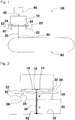
- Fig. 1 is a schematic sectional view of a melt blowing apparatus according to an embodiment of the present invention
- Fig. 2 is an enlarged schematic sectional view illustrating a component between a die 10 and a collecting surface 62 of a collector 60 of the melt blowing apparatus shown in Fig. 1
- a resin composition at least including a crystalline thermoplastic resin such as, for example, polyethylene terephthalate
- the resin melt 42 is directed to a die 10 discharging fiber materials.
- the fiber materials 50 discharged from the die 10 travel toward a collecting surface 62 of a collector 60.
- the die 10 has nozzle holes 12 that discharge the resin melt 42 and is provided with hot-air injection channels (hot-air emerging slots) 14, 14 on both sides of the nozzle holes 12.
- the fiber materials (or fibrous materials from molten resin) 50 discharged from the nozzle holes 12 with accompanying jet injected from the hot-air injection channels 14, 14 are first heated in a heating zone 26.
- the heating zone 26 is surrounded by a hollow cover 20 provided in a downstream side of the accompanying jet and is heated by a heating unit 23, such as a hot-air injector.
- the heating unit 23 is preferably configured to heat the fiber materials 50 from side surfaces of the hollow cover 20. It should be noted that the crystallization temperature is measured in accordance with JIS K 7121.
- the hollow cover 20 is provided below the nozzle holes 12 of the die 10 in the downstream side of the accompanying jet, if necessary, via a spacer part (not illustrated).
- Each of the upper and lower edges of the hollow cover 20 independently may be open or may have opening(s) so that the fiber materials 50 can pass through.
- thermoplastic resin Since the temperature of the fiber materials 50 discharged from the nozzle holes 12 generally decreases soon after discharge, it is difficult to promote crystallization of a thermoplastic resin, where the resin has a low crystallization speed. It comes to possible, however, by a heated space that has a temperature equal to or higher than the crystallization temperature (Tc) of the thermoplastic resin, in the heating zone 26, to promote crystallization of the fiber materials 50, even where the thermoplastic resin has a low crystallization speed.
- Tc crystallization temperature
- thermostability of the MB nonwoven fabric can be enhanced presumably because crystallization can be promoted at a stage of the fiber materials 50 while pseudo-drawing force by the accompanying jet is applied. As a result, for example, even if the fabric is exposed to high temperature, extensive shrinkage of the nonwoven fabric can be prevented.
- a heated part of the heating zone 26 is not particularly limited as long as a degree of crystallization of the fiber materials 50 can be enhanced in the heating zone 26, the heated part is preferably located, for example, near the nozzle holes 12.
- the location near the nozzle holes may be, for example, in a semispherical space having a radius of 5 cm from a center at each nozzle hole.
- a length of the heating zone in an up-and-down direction can be expressed as a distance H from the upper edge to the lower edge of the heating zone 26 in a line extending downwardly in a vertical direction from the nozzle holes 12 on the die 10.
- the distance H typically corresponds to a distance from the nozzle holes 12 to the lower edge 28 of the hollow cover 20 in the line extending downward from the nozzle holes in the vertical direction.
- the lower edge of the hollow cover 20 may be a highest (uppermost) point of the lower edge of the hollow cover 20 in a horizontal projection drawing, i.e., an elevation drawing, of the hollow cover part 20.
- the distance H may be set in accordance with the temperature of the heating zone 26 and may be, for example, 10 cm or longer, preferably 10.5 cm or longer, and more preferably 11 cm or longer. Although the distance H does not particularly have an upper limit as far as it does not deteriorate the effects of the present invention, it may be about 18 cm in order to enhance elongation of the MB nonwoven fabric.
- the fiber materials exposed to outside air are rapidly cooled after discharge.
- the present invention makes it possible to suppress rapid cooling of the fiber materials after discharge thanks to the heating zone that is adjusted to a certain temperature.
- the fiber materials taken at a position 10 cm below the nozzle holes 12 in the vertical direction may have, for example, a temperature of (Tc - 25) °C or higher and preferably (Tc - 20) °C or higher.
- An upper limit may be suitably selected in a range that allows crystallization of the fiber materials 50 to be promoted and may be, for example, (Tc + 10) °C or lower and preferably Tc °C or lower in terms of economic efficiency.
- the fiber materials taken at a position 10 cm below the nozzle holes 12 in the vertical direction may have, for example, a temperature of 105°C or higher and preferably 110°C or higher.
- a heating unit (heat source) 23 for heating the heating zone 26 is not particularly limited as long as it can heat an inside of the hollow cover 20, examples may include a heater or a hot-air injector. In terms of heat efficiency, a hot-air injector is preferable.
- the hollow cover 20 is formed with air blowing ports 22, 22 for introducing heated air flow 24 from a hot-air injector 23.
- the heated air flow 24, 24 is injected to front and back surfaces of the fiber materials 50 through the air blowing ports 22, 22.
- the heated air flow 24, 24 may be injected to the entire fiber materials 50 or to a part of the fiber materials 50 (for example, a part near the nozzle holes).
- a shape of the air blowing ports is not particularly limited as far as the ports allow heated air to be introduced to the inside of the hollow cover 20.
- the air blowing ports 22, 22 may have a width approximately equal to that of the fiber materials (for example, a width corresponding to an arranged width of a plurality of the nozzle holes 12 formed on the die 10).
- a temperature of the heated air flow 24 injected from the air blowing ports 22, 22 is not particularly limited as long as the heating zone can be heated to a predetermined temperature, and may be selected from a wide range of, for example, from about (Tc+30)°C to about (Tc+250)°C and preferably from about (Tc+40)°C to about (Tc+240)°C.
- the nozzle may preferably inject air at an amount per meter of its width within a range where travelling of the fiber materials is not disturbed, e.g., from about 0.5 to about 5 Nm 3 /min and preferably from about 1 to about 3 Nm 3 /min.
- the fiber materials 50 having passed through the heating zone 26 are exposed to outside air in an air gap zone 30 and are cooled thereby.
- the fiber materials 50 travel with the accompanying jet toward a collector 60 and pass through the air gap zone 30 having a predetermined range to be collected on a collecting surface 62.
- a length of the air gap zone 30 in the up-and-down direction can be expressed as a distance L from the lower edge 28 of the heating zone 26 (or the lower edge 28 of the hollow cover 20) to the collecting surface 62 of the collector 60 in the line extending downward in the vertical direction from the nozzle holes 12 on the die 10.
- the distance L typically corresponds to a height from the lower edge 28 of the hollow cover 20 to the collecting surface 62.
- the distance L may be a length from a vertically highest (uppermost) point of the lower edge of the hollow cover part 20 to a vertically highest (uppermost) point of the collecting surface 62 of the collector 60 in a horizontal projection figure, i.e., an elevation figure, of the hollow cover part 20 and the collector 60.
- the distance L is required to be 5 cm or longer in order to impart soft texture to the fiber materials 50 having passed through the heating zone 26 with the accompanying jet.
- the fiber materials 50 that have been pseudo-drawn in the heating zone and have an enhanced crystallization then travel through the air gap zone 30 with the accompanying jet so that the fiber materials can reach a bulky web state while maintaining a crystallized state.
- the distance L may preferably be 6 cm or longer and more preferably 8 cm or longer. Although the distance L does not particularly have an upper limit, it may be about 15 cm in order to enhance collection efficiency.
- a sum (H + L) of the distance H of the heating zone and the distance L of the air gap zone may be, for example, from about 13 to about 30 cm, preferably from about 15 to about 28 cm, and more preferably from about 18 to about 25 cm.
- the distance H of the heating zone and the distance L of the air gap zone may have a ratio of, for example, 1 ⁇ H/L ⁇ 3.5, may have a ratio of 1 ⁇ H/L ⁇ 2, and preferably 1 ⁇ H/L ⁇ 1.5.
- the hot air at the time of injection can have any temperature that is suitably set in accordance with a melting temperature of a resin composition used and may, for example, have a temperature substantially the same as a discharge temperature of the resin composition.
- the hot air can have any injection rate that is suitably set in a range that allows the hot air to provide pseudo-drawing effects to the fiber materials 50 in the heating zone as well as to loosen (split) the fiber materials 50 in the air gap zone 30.
- Such an injection rate may be, for example, from about 5 to about 30 Nm 3 /min, and preferably from about 10 to about 25 Nm 3 /min as an air amount per meter of the nozzle width.
- the collector 60 is not particularly limited as far as the collector is a typically used one for producing MB nonwoven fabrics, and the collector may be a rotary roll or a conveyor belt.
- the collector 60 may be a conveyor belt to be rotated in one direction as shown in Fig. 1 , on the collecting surface 62 of which the fiber materials 50 are collected such that the MB nonwoven fabric 52 is continuously produced as the conveyor belt rotates.
- the MB nonwoven fabric may be made of a resin composition containing a crystalline thermoplastic resin as a principal component, and may have, for example, a surface shrinkage ratio at (Tm ⁇ 3/4) °C of 20% or lower (preferably 17% or lower, more preferably 16% or lower), where Tm denotes the melting point of the crystalline thermoplastic resin, and a longitudinal 10% modulus (M MD ) at 30°C of 22 N/5cm or lower in the longitudinal direction (MD direction).
- Tm denotes the melting point of the crystalline thermoplastic resin
- M MD longitudinal 10% modulus
- the crystalline thermoplastic resin may include polyolefin-series, polyamide-series, and polyester-series thermoplastic resins.
- the resin composition preferably contains the crystalline thermoplastic resin in a proportion of 50 wt% or more, more preferably 80 wt% or more, further preferably 90 wt% or more, and particularly preferably 98 wt% or more.
- the resin composition may include an additive(s), for example, a delustering agent, such as titanium oxide, barium sulfate, and zinc sulfide; a heat stabilizer, such as phosphoric acid and phosphorous acid; a light stabilizer; an antioxidant; and/or a surface treatment agent, such as silicon oxide.
- a delustering agent such as titanium oxide, barium sulfate, and zinc sulfide
- a heat stabilizer such as phosphoric acid and phosphorous acid
- a light stabilizer such as an antioxidant
- a surface treatment agent such as silicon oxide.
- PET-series MB nonwoven fabric having soft texture as well as good thermostability at high temperature due to effective suppression of heat shrinkage.
- such a PET-series MB nonwoven fabric may be made of a resin composition containing a PET-series resin as a principal component.
- the expression "containing a PET-series resin as a principal component" used herein means that the resin composition contains a PET-series resin in a proportion of 50 wt% or more, preferably 80 wt% or more, more preferably 90 wt% or more, and particularly preferably 98 wt% or more of resin components constituting the composition.
- MB nonwoven fabric refers to MB nonwoven fabrics that are not limited to those of PET-series, and that the term “PET-series MB nonwoven fabric” may be used when reference is made particularly to an MB nonwoven fabric specifically made of a PET-series resin.
- the PET-series resin may be composed of a unit derived from ethylene glycol and a unit derived from terephthalic acid and may also contain less than 2.0 mol% of a copolymerization component according to intended uses.
- the MB nonwoven fabric (in particular, PET-series MB nonwoven fabric) according to the present invention makes it possible to enhance thermostability at around 200°C, which has conventionally been impossible for PET-series MB nonwoven fabrics, and to achieve a surface shrinkage ratio of 20% or lower at 200°C.
- the surface shrinkage ratio may be preferably 17% or lower, and more preferably 16% or lower. It should be noted that the surface shrinkage ratio is measured in accordance with a method described for Examples described later. Such reduction in the surface shrinkage ratio at high temperature makes it possible to process the fabric at a higher temperature, so that the higher temperature can, e.g., shorten time for molding processing.
- the MB nonwoven fabric according to the present invention makes it possible not only to enhance thermostability, but also to achieve soft texture, and may have a longitudinal 10% modulus (M MD ) at 30°C of 22 N/5cm or lower in the longitudinal direction (MD direction).
- the longitudinal 10% modulus (M MD ) at 30°C may preferably be 21 N/5cm or lower in the longitudinal direction (or MD direction).
- a transverse 10% modulus (M CD ) at 30°C may preferably be 18 N/5cm or lower and more preferably 16 N/5cm or lower in a transverse direction (or CD direction).
- the 10% modulus used herein means tensile stress at 10% stain and is, specifically, measured in accordance with a method described for Examples described later.
- the MB nonwoven fabric preferably has approximately the same 10% moduli in the longitudinal direction (or MD direction) and in the transverse direction (or CD direction), and a ratio (M MD /M CD ) of the 10% modulus (M MD ) in the longitudinal direction to the 10% modulus (M CD ) in the transverse direction may be, for example, in a range from about 1.00 to about 1.50, from about 1.05 to about 1.45, or from about 1.10 to about 1.40.
- the MB nonwoven fabric according to the present invention may have strength and elongation that do not practically cause problem in handling, and may have, for example, a longitudinal tensile strength of 10 N/5cm or higher, preferably 14 N/5cm or higher, and more preferably 18 N/5cm or higher in the longitudinal direction (stream direction or MD direction).
- the tensile strength is measured in accordance with a method described for Examples described later.
- the MB nonwoven fabric according to the present invention may have approximately the same tensile strengths in the longitudinal direction (or MD direction) and in the transverse direction (or CD direction), and a ratio (T MD /T CD ) of the tensile strength (T MD ) in the longitudinal direction to the tensile strength (T CD ) in the transverse direction may be, for example, in a range from about 1.00 to about 1.40, from about 1.00 to about 1.20, from about 1.10 to about 1.35, or from about 1.10 to about 1.20.
- the MB nonwoven fabric according to the present invention may have, for example, a longitudinal elongation ratio of 25% or higher and preferably 30% or higher in the longitudinal direction (or MD direction).
- the elongation ratio is measured in accordance with a method described for Examples described later.
- the MB nonwoven fabric according to the present invention may also have substantially the same elongation ratios in the longitudinal direction (MD direction) and in the transverse direction (CD direction), and a ratio (E MD /E CD ) of the elongation ratio (E MD ) in the longitudinal direction to the elongation ratio (E CD ) in the transverse direction may be, for example, in a range from about 0.80 to about 1.20, from about 0.80 to about 1.15, from about 0.90 to about 1.20, or from about 0.95 to about 1.15.
- the MB nonwoven fabric according to the present invention may have any average fiber diameter that is suitably set according to intended uses.
- the average fiber diameter is not particularly limited to a specific range, the average fiber diameter may be, for example, in a range from about 0.5 to about 10 ⁇ m, preferably from about 1 to about 8 ⁇ m, more preferably from about 1 to about 5 ⁇ m in terms of, for example, acoustic properties and strength of the nonwoven fabric.
- the average fiber diameter is measured in accordance with a method described for Examples described later.
- the MB nonwoven fabric according to the present invention may have any density that is suitably set according to intended uses.
- the density is not particularly limited to a specific range, the density may be, for example, in a range from about 0.1 to about 0.4 g/cm 3 , preferably from about 0.1 to about 0.3 g/cm 3 , and more preferably from about 0.1 to about 0.2 g/cm 3 in terms of, for example, acoustic properties.
- the MB nonwoven fabric according to the present invention may have any thickness that is suitably set according to intended uses.
- the thickness is not particularly limited to a specific range, the thickness may be, for example, in a range from about 50 to about 500 ⁇ m, preferably from about 80 to about 400 ⁇ m, and more preferably from about 100 to about 300 ⁇ m in terms of, for example, handling properties and acoustic properties.
- the MB nonwoven fabric according to the present invention may have any basis weight that is suitably set according to intended uses.
- the basis weight is not particularly limited to a specific range, the basis weight may be, for example, in a range from about 10 to about 100 g/m 2 , preferably from about 20 to about 70 g/m 2 , and more preferably from about 20 to about 50 g/m 2 in terms of, for example, acoustic properties and productivity.
- the MB nonwoven fabric according to the present invention may have any air permeability that is suitably set according to intended uses.
- the air permeability is not particularly limited to a specific range, the air permeability may be, for example, in a range from about 30 to about 90 cm 3 /cm 2 ⁇ s, preferably from about 35 to about 85 cm 3 /cm 2 ⁇ s, and more preferably from about 40 to about 80 cm 3 /cm 2 ⁇ s in terms of, for example, acoustic properties.
- the MB nonwoven fabric according to the present invention can be applied to various applications, such as medical and hygienic materials, industrial materials, daily commodities and clothing.
- the MB nonwoven fabric can suitably be applied to, e.g., acoustic materials for vehicles (in particular, acoustic materials for automobiles), high-frequency acoustic panels for outdoor use, and noise suppression sheets for electronic devices because the MB nonwoven fabric is excellent in high-frequency acoustic properties.
- the MB nonwoven fabric according to the present invention may be combined with various supports (for example, sheet-like resin members, fabrics) to be used as a laminate thanks to its excellent thermostability.
- the laminate may include, for example, a support and an MB nonwoven fabric that is thermocompression-bonded to at least one surface of the support, wherein the MB nonwoven fabric is a nonwoven fabric according to the present invention.
- the MB nonwoven fabric according to the present invention has soft texture and good adhesion to a support, and may have, for example, a peeling strength (T-peel test) of 0.2 N/5cm or higher, preferably 0.25 N/5cm or higher, and more preferably 0.3 N/5cm or higher in a thermocompression-bonding surface between the nonwoven fabric and the support, the peeling strength being measured in accordance with JIS K 6854-3.
- the support may suitably be selected from various materials, including various resin sheets and fabrics (woven fabrics, knitted fabrics, nonwoven fabrics, felts), according to intended uses.
- the fabrics may be composed of any of natural fibers, regenerated fibers, semisynthetic fibers, and synthetic fibers.
- the nonwoven fabrics may be, for example, any of wet-laid nonwoven fabrics, dry-laid nonwoven fabrics (for example, chemically-bonded, thermally-bonded, needle-punched, spunlace, stitch-bonded, or air-laid nonwoven fabrics), and direct-spun nonwoven fabrics (for example, spun-bonded nonwoven fabrics).
- the support may preferably be a felt or a nonwoven fabric (for example, a needle-punched nonwoven fabric).
- the laminate can be used for the various applications mentioned above for the MB nonwoven fabric.
- the laminate can suitably be used as acoustic materials for vehicles (in particular, acoustic materials for automobiles), high-frequency acoustic panels for outdoor use, and noise suppression sheets for electronic devices because the laminate is excellent in high-frequency acoustic properties.
- An MB nonwoven fiber structure was observed using a scanning electron microscope (SEM). From an SEM image, 100 fibers were randomly selected and measured for fiber diameters to calculate a number average fiber diameter. The number average fiber diameter was used as an average fiber diameter of the fibers.
- the volume of the nonwoven fabric was obtained to determine from the calculation of a density of the MB nonwoven fabric from these measurements.
- Each of the samples cut to a length of 5 cm x 5 cm in the longitudinal and transverse directions was elongated at a tensile speed of 10 cm/min in accordance with JIS L 1906, using an Autograph manufactured by Shimadzu Corporation, to determine a load value and an elongation ratio at which breakage occurs as tensile strength and elongation of the sample, respectively.
- Tensile stress at an elongation of 10% was measured as a 10% modulus.
- a 20-cm square sample was prepared and marked with lines drawn at positions 5 cm inward from respective sides so as to mark a 10-cm square inside the sample.
- the sample was then placed in an oven heated to 200°C and was subjected to heating for 1 minute under no tension.
- the marked area was measured for the dimensions before and after heating to calculate a surface shrinkage ratio by the following formula.
- Surface shrinkage ratio Pre-heating surface area ⁇ Post-heating surface area / Pre-heating surface area ⁇ 100
- a 20-cm square sample and a 20-cm square support (a felt having a basis weight of about 600 g/m 2 ) were overlaid on each other. Then, the sample and the support in an overlapped state were pressed between iron plates to be heated for 1 minute at a temperature of 200°C under pressure of 200 Pa, and thus obtained laminate was taken out. The laminate was evaluated in terms of molding processability at 200°C, on a scale of A and B.
- A indicates that the laminate did not have specific defects in appearance, such as winkles, after heating, and the MB nonwoven fabric was not deteriorated in soft texture
- B indicates that the laminate had defects in appearance, such as winkles, after heating and/or the MB nonwoven fabric was deteriorated in soft texture.
- the laminate obtained for evaluating molding processability at 200°C was subjected to peeling text to determine peeling strength between the sample and the support in accordance with T-peel test in JIS K 6854-3.
- a PET resin having a crystallization temperature (Tc) of 130°C having a melt viscosity at 300°C of 80 Pa ⁇ s was molten to give a resin melt, and the resin melt was supplied to a die having a nozzle with a nozzle hole diameter (diameter) of 0.3 mm/hole, a ratio of a nozzle hole length to a nozzle hole diameter (L/D) of 10, and a nozzle hole pitch of 0.75 mm.
- Tc crystallization temperature
- the resin melt was then discharged from the nozzle at a spinning temperature of 320°C at a discharge rate of 0.13 g/min per hole, with injecting hot air having a temperature of 340°C as accompanying jet at an air amount per meter of the nozzle width of 15 Nm 3 /min.
- An ambient temperature 5 cm below the nozzle holes in the vertical direction (hereinafter, referred to as "temperature 5 cm below the nozzle") was 165.0°C.
- a heat-insulating cover having a length of 11.0 cm was provided below the nozzle to keep a space below the nozzle heated, and hot air having a temperature of 350°C as heated air flow was blown in toward the nozzle holes from both sides of the nozzle through air blowing ports provided to side surfaces of the heat-insulating cover at an air amount per meter of the nozzle width of 2 Nm 3 /min in order to heat the fiber materials discharged from the nozzle.
- a temperature of the fiber materials measured 10 cm below the spinning nozzle was 138.9°C.
- the fiber materials from the heat-insulating cover were further allowed to travel through an air gap zone having a length of 9.0 cm and were collected on a collecting net to form a PET-series MB nonwoven fabric having a basis weight of 30 g/cm 2 without being subjected to a post-processing.
- the heating zone H had a length of 11.0 cm
- the air gap zone L had a length of 9.0 cm.
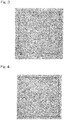
- Fig. 3 shows the obtained MB nonwoven fabric after being subjected to heating at 200°C.
- Example 2 was carried out in the same manner as that of Example 1, except that the heated air flow had a blowing temperature of 180°C.
- the temperature 5 cm below the nozzle was 141.1°C
- the temperature of the fiber materials measured 10 cm below the spinning nozzle was 110.3°C.
- Fig. 4 shows the obtained MB nonwoven fabric after being subjected to heating at 200°C.
- Example 3 was carried out in the same manner as that of Example 1, except that the heat-insulating cover provided below the nozzle had a length of 15.0 cm, that the air gap zone had a length of 5.0 cm, and that the heated air flow had a blowing temperature of 300°C.
- the temperature 5 cm below the nozzle was 142.0°C
- the temperature of the fiber materials measured 10 cm below the spinning nozzle was 130.7°C.
- Example 4 was carried out in the same manner as that of Example 1, except that the heat-insulating cover provided below the nozzle had a length of 15.0 cm and that the air gap zone had a length of 8.0 cm.
- the temperature 5 cm below the nozzle was 145.2°C
- the temperature of the fiber materials measured 10 cm below the spinning nozzle was 137.6°C.
- Example 5 was carried out in the same manner as that of Example 1, except that the heat-insulating cover provided below the nozzle had a length of 17.5 cm, that the air gap zone had a length of 5.5 cm, and that the heated air flow had a blowing temperature of 180°C.
- the temperature 5 cm below the nozzle was 138.9°C
- the temperature of the fiber materials measured 10 cm below the spinning nozzle was 123.6°C.
- Comparative Example 1 was carried out in the same manner as that of Example 1, except that blowing of the heated air flow through the air blowing ports was not carried out in the heat-insulating cover. That is, in Comparative Example 1, the distance H was 0 cm, and the distance L was 9.0 cm because the inside of the cover was not heated so that the space below the spinning nozzle was not heated to a temperature equal to or higher than the crystallization temperature of the PET-series resin. The temperature 5 cm below the nozzle was 119.1°C, and the temperature of the resin measured 10 cm below the spinning nozzle was 100.8°C.
- Comparative Example 2 was carried out in the same manner as that of Example 1, except that after the melt was discharged from the nozzle, the melt was directly collected on a collecting net provided 13 cm below the nozzle holes without providing the heat-insulating cover as well as blowing the heated air flow. That is, in Comparative Example 2, the distance H was 0 cm, and the distance L was 13.0 cm because the space below the spinning nozzle was not heated to a temperature equal to or higher than the crystallization temperature of the PET-series resin. The temperature 5 cm below the nozzle was 82.6°C, and the temperature of the resin measured 10 cm below the spinning nozzle was 54.6°C.
- Fig. 5 shows the obtained MB nonwoven fabric after being subjected to heating at 200°C.
- Comparative Example 3 was carried out in the same manner as that of Example 1, except that the heating zone H had a length of 10.5 cm and that the air gap zone L had a length of 2.0 cm. That is, in Comparative Example 3, the distance H was 10.5 cm, and the distance L was 2 cm. In this Comparative Example, the temperature 5 cm below the nozzle was 148.0°C, and the temperature of the fiber materials measured 10 cm below the spinning nozzle was 119.3°C. [Table 1] H Temp. 5cm below nozzle L Temp.
- the temperature of the resin measured 10 cm below the spinning nozzle in Comparative Example 1 was lower than those in the Examples because Comparative Example 1 did not perform heating in the heat-insulating cover. Further, presumably because crystallization was not promoted due to absence of the heating zone, the obtained sample had a surface shrinkage ratio at 200°C exceeding 30%. Also, when compared with those of the Examples, the MB nonwoven fabric of Comparative Example 1 had lower strength. The laminate including the support and the MB nonwoven fabric that were thermocompression-bonded to each other had winkles in appearance because the MB nonwoven fabric was greatly shrunk due to heating, thus indicating insufficient molding processability.
- the fiber materials from the heating zone could not be loosened to be bulky because of too short distance L, i.e., the length of the air gap zone, of 2.0 cm.
- the resultant nonwoven fabric had a value of the longitudinal 10% modulus exceeding 30 N/5cm in the longitudinal direction (MD direction) and a hard texture.
- the obtained nonwoven fabric had an air permeability half as high as those of Examples.
- the laminate including the support and the MB nonwoven fabric that were thermocompression-bonded to each other was firm to the touch. Further, the nonwoven fabric did not have soft texture, resulting in insufficient molding processability.
- Table 2 shows peeling strengths of the laminates each including the support and the MB nonwoven fabric obtained in Examples 1 to 5 which are thermocompression-bonded to each other. As shown in Table 2, all the laminates having the MB nonwoven fabrics obtained from Examples 1 to 5 had peeling strength higher than 0.3 N/5cm.
- MB nonwoven fabrics and laminates using the same according to the present invention can suitably be applied to various applications, such as medical and hygienic materials, industrial materials, daily commodities and clothing.
- the MB nonwoven fabrics and the laminates can suitably be applied to acoustic materials for vehicles (in particular, acoustic materials for automobiles), high-frequency acoustic panels for outdoor use, and noise suppression sheets for electronic devices because of their excellent high-frequency acoustic properties.
Landscapes
- Engineering & Computer Science (AREA)
- Textile Engineering (AREA)
- Mechanical Engineering (AREA)
- Chemical & Material Sciences (AREA)
- Chemical Kinetics & Catalysis (AREA)
- Nonwoven Fabrics (AREA)
- Vehicle Interior And Exterior Ornaments, Soundproofing, And Insulation (AREA)
- Laminated Bodies (AREA)
- Soundproofing, Sound Blocking, And Sound Damping (AREA)
Abstract
Description
- This application is based on an claims Convention priority to Japanese patent application No.
2017-155193, filed August 10, 2017 - The present invention relates to a melt blown nonwoven fabric having improved thermostability and soft texture, to a laminate using the same, to a method of producing a melt blown nonwoven fabric as well as to a melt blowing apparatus.
- Although polyethylene terephthalate (PET) resin has been utilized in various forms as nonwoven fabrics because of their high versatility, their application is little expanded to be used as melt blown (MB) nonwoven fabrics. One of the reasons is that PET has a lower crystallization speed than those of other crystalline polymers that are frequently used for melt blown nonwoven fabrics. In other word, since polyethylene terephthalate (PET) resin cannot achieve a sufficiently high degree of crystallization in melt blowing process because of their lower crystallization speed, resulting in low thermostability of the obtained melt blown (MB) nonwoven fabrics. Such MB nonwoven fabrics having low thermostability, for example, would considerably shrink when the MB nonwoven fabrics are situated at a temperature of 200°C, which is higher than a glass transition point (approximately 130°C) of PET by 70 to 80°C, under no tension.
- For example, Patent Document 1 (
JP Laid-open Patent Publication No. H03-045768 - [Patent Document 1]
JP Laid-open Patent Publication No. H03-045768 - However, Patent Document 1 requires the web to be subjected to an additional heat treatment process, so that the resultant nonwoven fabric has hard texture due to heating of the web itself. Moreover, thermostability at high temperature, such as 100°C or higher (for example, at 200°C) of the MB nonwoven fabric is not described. Further, the MB nonwoven fabric produced by such a production process inevitably has a lower strength than those of typical MB nonwoven fabrics made of easily-crystallized polymers.
- Therefore, an object of the present invention is to provide a PET-series MB nonwoven fabric having a low surface shrinkage ratio at 200°C and having soft texture, as well as a laminate using the same.
- Another object of the present invention is to provide a melt blowing method (or a method of producing a MB nonwoven fabric) and a melt blowing apparatus both of which are capable of imparting soft texture to a thermoplastic resin MB nonwoven fabric and improving thermostability of the fabric.
- The inventors of the present invention have made extensive efforts to achieve the objects and first found that (i) since there is no drawing step after spinning in melt blowing process, there is a possibility that the melt blown fabric under heated condition, where heating makes it easy for the molecules to move, may cause excessive heat shrinkage due to "propensity for taking coil shapes" inherent to PET molecules. With the progress in the study, the inventors found that (ii) heat shrinkage at a temperature as high as 200°C can be suppressed even for PET-series MB nonwoven fabrics by providing a heating zone, following melt blowing spinning, so as to promote crystallization of PET molecules and to provide pseudo-drawing effects by accompanying jet. Further, the inventors of the present invention identified a new problem that in such a case, soft texture of MB nonwoven fabrics is deteriorated. The inventors continued the study to solve the new problem and finally have found that (iii) by providing an air gap zone having a predetermined range where fiber materials travel with accompanying jet following the heating zone, MB nonwoven fabrics having not only thermostability but also soft texture can be successfully obtained. The inventors thus achieved the present invention.
- That is, the present invention may include the following aspects.
- Aspect 1
A melt blown nonwoven fabric comprising a resin composition including a polyethylene terephthalate-series resin as a principal component, wherein the melt blown nonwoven fabric has a surface shrinkage ratio at 200°C of 20% or lower and a longitudinal 10% modulus at 30°C of 22 N/5cm or lower. - Aspect 2
The melt blown nonwoven fabric according to aspect 1, wherein the melt blown nonwoven fabric has a longitudinal tensile strength (TMD) of 10 N/5cm or higher and a ratio (TMD/TCD) of the longitudinal tensile strength (TMD) to a transverse tensile strength (TCD) in a range from 1.00 to 1.40. - Aspect 3
The melt blown nonwoven fabric according to aspect 1 or 2, wherein the melt blown nonwoven fabric has a longitudinal elongation ratio (EMD) of 25% or higher and a ratio (EMD/ECD) of the longitudinal elongation ratio (EMD) to a transverse elongation ratio (ECD) in a range from 0.80 to 1.20. - Aspect 4
The melt blown nonwoven fabric according to any one of aspects 1 to 3, wherein the melt blown nonwoven fabric has an air permeability of from 30 to 90 cm3/cm2·s in accordance with JIS L 1906. - Aspect 5
The melt blown nonwoven fabric according to any one of aspects 1 to 4, wherein the melt blown nonwoven fabric is used for an acoustic material for a vehicle. - Aspect 6
A laminate comprising a support and a melt blown nonwoven fabric that is thermocompression-bonded to at least one surface of the support, wherein the melt blown nonwoven fabric is a melt blown nonwoven fabric recited in any one of aspects 1 to 5. - Aspect 7
The laminate according to aspect 6, wherein the laminate has a peeling strength (T-peel) of 0.2 N/5cm or higher in accordance with JIS K 6854-3 at a thermocompression-bonded surface between the melt blown nonwoven fabric and the support. - Aspect 8
The laminate according to aspect 6 or 7, wherein the support is formed of a nonwoven fabric or a felt. - Aspect 9
An acoustic material for a vehicle, comprising a laminate recited in any one of aspects 6 to 8. -
Aspect 10
A method of producing a melt blown nonwoven fabric, the method comprising:- heating a resin composition including a crystalline thermoplastic resin to give a melt and discharging the melt with accompanying jet (air stream that accompanies the discharged melt) through nozzle holes to give fiber materials;
- heating the fiber materials discharged through the nozzle holes in a heating zone;
- exposing the heated fiber materials to outside air in an air gap zone to cool the fiber materials; and
- collecting the cooled fiber materials on a collecting surface to obtain a web,
- wherein at least a part of the heating zone is heated to a crystallization temperature of the crystalline thermoplastic resin or higher; and
- the air gap zone is a space between a lower edge of the heating zone and the collecting surface, the space having a distance L of 5 cm or longer in a line extending downwardly from the nozzle holes in a vertical direction.
- Aspect 11
The method of producing a melt blown nonwoven fabric according toaspect 10, wherein the heating zone is a space between the nozzle holes and the lower edge of the heating zone, the space having a distance H of 10 cm or longer in the line extending downwardly from the nozzle holes in the vertical direction. -
Aspect 12
The method of producing a melt blown nonwoven fabric according toaspect 10 or 11, wherein the fiber materials have a temperature equal to or higher than the crystallization temperature (Tc) - 25°C, at aposition 10 cm below the nozzle holes in the vertical direction in the heating zone. - Aspect 13
The method of producing a melt blown nonwoven fabric recited in any one ofaspects 10 to 12, wherein the crystalline thermoplastic resin is a polyethylene terephthalate-series resin. -
Aspect 14
A melt blowing apparatus at least comprising:- an extruder configured to heat a resin composition including a crystalline thermoplastic resin to give a melt;
- a die configured to discharge the melt with an accompanying jet to give fiber materials;
- a hollow cover provided in a downstream side of the accompanying jet and configured to surround the fiber materials;
- a heating unit configured to heat the fiber materials to a predetermined temperature (for example, to a temperature equal to or higher than a crystallization temperature of the crystalline thermoplastic resin);
- a collector having a collecting surface configured to collect the fiber materials flowing from the hollow cover in a downward direction of the accompanying jet,
- wherein the hollow cover and the collector are separated by a distance of 5 cm or longer between a lower edge of the hollow cover and the collecting surface in a line extending downwardly from the nozzle holes in a vertical direction.
- Aspect 15
The melt blowing apparatus according toaspect 14, wherein the nozzle holes and the lower edge of the hollow cover are separated by a distance of 10 cm or longer in the line extending downwardly from the nozzle holes in the vertical direction. - Aspect 16
The melt blowing apparatus according toaspect 14 or 15, wherein the hollow cover is formed with an air blowing port configured to introduce heated air. - According to an MB nonwoven fabric of the present invention, a PET-series MB nonwoven fabric having soft texture and excellent thermostability at high temperature of 200°C as well as a laminate using the same can be obtained.
- Further, the present invention can provide a melt blowing method and a melt blowing apparatus capable of imparting soft texture to an MB nonwoven fabric and improving thermostability of the fabric, even where a crystalline thermoplastic resin (in particular, resins having low crystallization speeds) is used, thanks to the specific heating zone and air gap zone following spinning zone.
- The present invention will be more clearly understood from the following description of preferred embodiments thereof, when taken in conjunction with the accompanying drawings. However, the embodiments and the drawings are given only for the purpose of illustration and explanation, and are not to be taken as limiting the scope of the present invention in any way whatsoever, which scope is to be determined by the appended claims. In the figures,
-
Fig. 1 is a schematic sectional view of a melt blowing apparatus according to an embodiment of the present invention; -
Fig. 2 is an enlarged schematic sectional view illustrating a component between a die 10 and a collectingsurface 62 of acollector 60 of the melt blowing apparatus shown inFig. 1 ; -
Fig. 3 is an image of an MB nonwoven fabric of Example 1 after heating test; -
Fig. 4 is an image of an MB nonwoven fabric of Example 2 after heating test; and -
Fig. 5 is an image of an MB nonwoven fabric of Comparative Example 2 after heating test. - Hereinafter, the embodiments of the present invention will be explained with reference to the drawings. It should be noted that the present invention is not limited to the illustrated embodiments.
-
Fig. 1 is a schematic sectional view of a melt blowing apparatus according to an embodiment of the present invention, andFig. 2 is an enlarged schematic sectional view illustrating a component between a die 10 and a collectingsurface 62 of acollector 60 of the melt blowing apparatus shown inFig. 1 . As shown inFig. 1 , in a melt blowing apparatus 100, a resin composition at least including a crystalline thermoplastic resin (such as, for example, polyethylene terephthalate) is heated in anextruder 40 to give a resin melt, and theresin melt 42 is directed to a die 10 discharging fiber materials. Next, thefiber materials 50 discharged from the die 10 travel toward a collectingsurface 62 of acollector 60. - As shown in
Fig. 2 , thedie 10 has nozzle holes 12 that discharge theresin melt 42 and is provided with hot-air injection channels (hot-air emerging slots) 14, 14 on both sides of the nozzle holes 12. Following the discharging, the fiber materials (or fibrous materials from molten resin) 50 discharged from the nozzle holes 12 with accompanying jet injected from the hot-air injection channels heating zone 26. Theheating zone 26 is surrounded by ahollow cover 20 provided in a downstream side of the accompanying jet and is heated by aheating unit 23, such as a hot-air injector. This configuration makes it possible to heat at least a part of the heating zone 26 (for example, at a position 5 cm below the nozzle holes) to have a temperature equal to or higher than a crystallization temperature (Tc) of the thermoplastic resin. In view of effective heating, theheating unit 23 is preferably configured to heat thefiber materials 50 from side surfaces of thehollow cover 20. It should be noted that the crystallization temperature is measured in accordance with JIS K 7121. - The
hollow cover 20 is provided below the nozzle holes 12 of the die 10 in the downstream side of the accompanying jet, if necessary, via a spacer part (not illustrated). Each of the upper and lower edges of thehollow cover 20 independently may be open or may have opening(s) so that thefiber materials 50 can pass through. - Since the temperature of the
fiber materials 50 discharged from the nozzle holes 12 generally decreases soon after discharge, it is difficult to promote crystallization of a thermoplastic resin, where the resin has a low crystallization speed. It comes to possible, however, by a heated space that has a temperature equal to or higher than the crystallization temperature (Tc) of the thermoplastic resin, in theheating zone 26, to promote crystallization of thefiber materials 50, even where the thermoplastic resin has a low crystallization speed. - Thus, thermostability of the MB nonwoven fabric can be enhanced presumably because crystallization can be promoted at a stage of the
fiber materials 50 while pseudo-drawing force by the accompanying jet is applied. As a result, for example, even if the fabric is exposed to high temperature, extensive shrinkage of the nonwoven fabric can be prevented. - Although a heated part of the
heating zone 26 is not particularly limited as long as a degree of crystallization of thefiber materials 50 can be enhanced in theheating zone 26, the heated part is preferably located, for example, near the nozzle holes 12. The location near the nozzle holes may be, for example, in a semispherical space having a radius of 5 cm from a center at each nozzle hole. - A length of the heating zone in an up-and-down direction can be expressed as a distance H from the upper edge to the lower edge of the
heating zone 26 in a line extending downwardly in a vertical direction from the nozzle holes 12 on thedie 10. The distance H typically corresponds to a distance from the nozzle holes 12 to thelower edge 28 of thehollow cover 20 in the line extending downward from the nozzle holes in the vertical direction. It should be noted that where the lower edge of thehollow cover 20 has uneven shape in the up-and-down direction, the lower edge of thehollow cover 20 may be a highest (uppermost) point of the lower edge of thehollow cover 20 in a horizontal projection drawing, i.e., an elevation drawing, of thehollow cover part 20. - The distance H may be set in accordance with the temperature of the
heating zone 26 and may be, for example, 10 cm or longer, preferably 10.5 cm or longer, and more preferably 11 cm or longer. Although the distance H does not particularly have an upper limit as far as it does not deteriorate the effects of the present invention, it may be about 18 cm in order to enhance elongation of the MB nonwoven fabric. - Without the heating zone, the fiber materials exposed to outside air are rapidly cooled after discharge. The present invention, however, makes it possible to suppress rapid cooling of the fiber materials after discharge thanks to the heating zone that is adjusted to a certain temperature. For example, the fiber materials taken at a
position 10 cm below the nozzle holes 12 in the vertical direction may have, for example, a temperature of (Tc - 25) °C or higher and preferably (Tc - 20) °C or higher. An upper limit may be suitably selected in a range that allows crystallization of thefiber materials 50 to be promoted and may be, for example, (Tc + 10) °C or lower and preferably Tc °C or lower in terms of economic efficiency. - For example, in the case of a polyethylene terephthalate resin composition, the fiber materials taken at a
position 10 cm below the nozzle holes 12 in the vertical direction may have, for example, a temperature of 105°C or higher and preferably 110°C or higher. - A heating unit (heat source) 23 for heating the
heating zone 26 is not particularly limited as long as it can heat an inside of thehollow cover 20, examples may include a heater or a hot-air injector. In terms of heat efficiency, a hot-air injector is preferable. For example, as shown inFig. 2 , thehollow cover 20 is formed withair blowing ports heated air flow 24 from a hot-air injector 23. In this case, theheated air flow fiber materials 50 through theair blowing ports heated air flow entire fiber materials 50 or to a part of the fiber materials 50 (for example, a part near the nozzle holes). A shape of the air blowing ports is not particularly limited as far as the ports allow heated air to be introduced to the inside of thehollow cover 20. There may be one or more windows having a round shape or a polygonal shape provided on the hollow cover. For example, in order to uniformly heat the fiber materials in a widthwise direction thereof, theair blowing ports - A temperature of the
heated air flow 24 injected from theair blowing ports - The
fiber materials 50 having passed through theheating zone 26 are exposed to outside air in anair gap zone 30 and are cooled thereby. In theair gap zone 30, thefiber materials 50 travel with the accompanying jet toward acollector 60 and pass through theair gap zone 30 having a predetermined range to be collected on a collectingsurface 62. - A length of the
air gap zone 30 in the up-and-down direction can be expressed as a distance L from thelower edge 28 of the heating zone 26 (or thelower edge 28 of the hollow cover 20) to the collectingsurface 62 of thecollector 60 in the line extending downward in the vertical direction from the nozzle holes 12 on thedie 10. The distance L typically corresponds to a height from thelower edge 28 of thehollow cover 20 to the collectingsurface 62. It should be noted that where thelower edge 28 of thehollow cover 20 and the collectingsurface 62 of thecollector 60 have uneven shapes in the up-and-down direction, the distance L may be a length from a vertically highest (uppermost) point of the lower edge of thehollow cover part 20 to a vertically highest (uppermost) point of the collectingsurface 62 of thecollector 60 in a horizontal projection figure, i.e., an elevation figure, of thehollow cover part 20 and thecollector 60. - The distance L is required to be 5 cm or longer in order to impart soft texture to the
fiber materials 50 having passed through theheating zone 26 with the accompanying jet. Thefiber materials 50 that have been pseudo-drawn in the heating zone and have an enhanced crystallization then travel through theair gap zone 30 with the accompanying jet so that the fiber materials can reach a bulky web state while maintaining a crystallized state. As a result, it is possible to provide an MB nonwoven fabric with soft texture. The distance L may preferably be 6 cm or longer and more preferably 8 cm or longer. Although the distance L does not particularly have an upper limit, it may be about 15 cm in order to enhance collection efficiency. - A sum (H + L) of the distance H of the heating zone and the distance L of the air gap zone may be, for example, from about 13 to about 30 cm, preferably from about 15 to about 28 cm, and more preferably from about 18 to about 25 cm. Also, the distance H of the heating zone and the distance L of the air gap zone may have a ratio of, for example, 1 < H/L < 3.5, may have a ratio of 1 < H/L < 2, and preferably 1 <H/L< 1.5.
- With respect to the accompanying jet injected from the hot-
air injection channels fiber materials 50 in the heating zone as well as to loosen (split) thefiber materials 50 in theair gap zone 30. Such an injection rate may be, for example, from about 5 to about 30 Nm3/min, and preferably from about 10 to about 25 Nm3/min as an air amount per meter of the nozzle width. - The
collector 60 is not particularly limited as far as the collector is a typically used one for producing MB nonwoven fabrics, and the collector may be a rotary roll or a conveyor belt. For example, thecollector 60 may be a conveyor belt to be rotated in one direction as shown inFig. 1 , on the collectingsurface 62 of which thefiber materials 50 are collected such that the MBnonwoven fabric 52 is continuously produced as the conveyor belt rotates. - In the melt blowing method described above, since the fiber materials discharged from the nozzle together with the accompanying jet is subjected to the specific processes, it is possible to produce an MB nonwoven fabric from a crystalline thermoplastic resin, the fabric having good thermostability at high temperature as well as having soft texture.
- For example, the MB nonwoven fabric may be made of a resin composition containing a crystalline thermoplastic resin as a principal component, and may have, for example, a surface shrinkage ratio at (Tm × 3/4) °C of 20% or lower (preferably 17% or lower, more preferably 16% or lower), where Tm denotes the melting point of the crystalline thermoplastic resin, and a longitudinal 10% modulus (MMD) at 30°C of 22 N/5cm or lower in the longitudinal direction (MD direction). Examples of the crystalline thermoplastic resin may include polyolefin-series, polyamide-series, and polyester-series thermoplastic resins. The resin composition preferably contains the crystalline thermoplastic resin in a proportion of 50 wt% or more, more preferably 80 wt% or more, further preferably 90 wt% or more, and particularly preferably 98 wt% or more.
- The resin composition may include an additive(s), for example, a delustering agent, such as titanium oxide, barium sulfate, and zinc sulfide; a heat stabilizer, such as phosphoric acid and phosphorous acid; a light stabilizer; an antioxidant; and/or a surface treatment agent, such as silicon oxide. These additives may be added in advance to a polymerization system in the polymerization process of the crystalline thermoplastic resin, or added when the crystalline thermoplastic resin is heated to give a melt after polymerization.
- In particular, according to the melt blowing method, even where a polyethylene terephthalate-series (PET) resin having a low crystallization speed is used, it is possible to produce the PET-series MB nonwoven fabric having soft texture as well as good thermostability at high temperature due to effective suppression of heat shrinkage.
- For example, such a PET-series MB nonwoven fabric may be made of a resin composition containing a PET-series resin as a principal component. The expression "containing a PET-series resin as a principal component" used herein means that the resin composition contains a PET-series resin in a proportion of 50 wt% or more, preferably 80 wt% or more, more preferably 90 wt% or more, and particularly preferably 98 wt% or more of resin components constituting the composition. It should be noted that the term "MB nonwoven fabric" refers to MB nonwoven fabrics that are not limited to those of PET-series, and that the term "PET-series MB nonwoven fabric" may be used when reference is made particularly to an MB nonwoven fabric specifically made of a PET-series resin.
- It should be noted that the PET-series resin may be composed of a unit derived from ethylene glycol and a unit derived from terephthalic acid and may also contain less than 2.0 mol% of a copolymerization component according to intended uses.
- The MB nonwoven fabric (in particular, PET-series MB nonwoven fabric) according to the present invention makes it possible to enhance thermostability at around 200°C, which has conventionally been impossible for PET-series MB nonwoven fabrics, and to achieve a surface shrinkage ratio of 20% or lower at 200°C. The surface shrinkage ratio may be preferably 17% or lower, and more preferably 16% or lower. It should be noted that the surface shrinkage ratio is measured in accordance with a method described for Examples described later. Such reduction in the surface shrinkage ratio at high temperature makes it possible to process the fabric at a higher temperature, so that the higher temperature can, e.g., shorten time for molding processing.
- The MB nonwoven fabric according to the present invention makes it possible not only to enhance thermostability, but also to achieve soft texture, and may have a longitudinal 10% modulus (MMD) at 30°C of 22 N/5cm or lower in the longitudinal direction (MD direction). The longitudinal 10% modulus (MMD) at 30°C may preferably be 21 N/5cm or lower in the longitudinal direction (or MD direction). Also, a transverse 10% modulus (MCD) at 30°C may preferably be 18 N/5cm or lower and more preferably 16 N/5cm or lower in a transverse direction (or CD direction). The 10% modulus used herein means tensile stress at 10% stain and is, specifically, measured in accordance with a method described for Examples described later. In order to maintain soft texture, the MB nonwoven fabric preferably has approximately the same 10% moduli in the longitudinal direction (or MD direction) and in the transverse direction (or CD direction), and a ratio (MMD/MCD) of the 10% modulus (MMD) in the longitudinal direction to the 10% modulus (MCD) in the transverse direction may be, for example, in a range from about 1.00 to about 1.50, from about 1.05 to about 1.45, or from about 1.10 to about 1.40.
- The MB nonwoven fabric according to the present invention may have strength and elongation that do not practically cause problem in handling, and may have, for example, a longitudinal tensile strength of 10 N/5cm or higher, preferably 14 N/5cm or higher, and more preferably 18 N/5cm or higher in the longitudinal direction (stream direction or MD direction). The tensile strength is measured in accordance with a method described for Examples described later.
- The MB nonwoven fabric according to the present invention may have approximately the same tensile strengths in the longitudinal direction (or MD direction) and in the transverse direction (or CD direction), and a ratio (TMD/TCD) of the tensile strength (TMD) in the longitudinal direction to the tensile strength (TCD) in the transverse direction may be, for example, in a range from about 1.00 to about 1.40, from about 1.00 to about 1.20, from about 1.10 to about 1.35, or from about 1.10 to about 1.20.
- The MB nonwoven fabric according to the present invention may have, for example, a longitudinal elongation ratio of 25% or higher and preferably 30% or higher in the longitudinal direction (or MD direction). The elongation ratio is measured in accordance with a method described for Examples described later.
- The MB nonwoven fabric according to the present invention may also have substantially the same elongation ratios in the longitudinal direction (MD direction) and in the transverse direction (CD direction), and a ratio (EMD/ECD) of the elongation ratio (EMD) in the longitudinal direction to the elongation ratio (ECD) in the transverse direction may be, for example, in a range from about 0.80 to about 1.20, from about 0.80 to about 1.15, from about 0.90 to about 1.20, or from about 0.95 to about 1.15.
- The MB nonwoven fabric according to the present invention may have any average fiber diameter that is suitably set according to intended uses. Although the average fiber diameter is not particularly limited to a specific range, the average fiber diameter may be, for example, in a range from about 0.5 to about 10 µm, preferably from about 1 to about 8 µm, more preferably from about 1 to about 5 µm in terms of, for example, acoustic properties and strength of the nonwoven fabric. The average fiber diameter is measured in accordance with a method described for Examples described later.
- The MB nonwoven fabric according to the present invention may have any density that is suitably set according to intended uses. Although the density is not particularly limited to a specific range, the density may be, for example, in a range from about 0.1 to about 0.4 g/cm3, preferably from about 0.1 to about 0.3 g/cm3, and more preferably from about 0.1 to about 0.2 g/cm3 in terms of, for example, acoustic properties.
- The MB nonwoven fabric according to the present invention may have any thickness that is suitably set according to intended uses. Although the thickness is not particularly limited to a specific range, the thickness may be, for example, in a range from about 50 to about 500 µm, preferably from about 80 to about 400 µm, and more preferably from about 100 to about 300 µm in terms of, for example, handling properties and acoustic properties.
- The MB nonwoven fabric according to the present invention may have any basis weight that is suitably set according to intended uses. Although the basis weight is not particularly limited to a specific range, the basis weight may be, for example, in a range from about 10 to about 100 g/m2, preferably from about 20 to about 70 g/m2, and more preferably from about 20 to about 50 g/m2 in terms of, for example, acoustic properties and productivity.
- The MB nonwoven fabric according to the present invention may have any air permeability that is suitably set according to intended uses. Although the air permeability is not particularly limited to a specific range, the air permeability may be, for example, in a range from about 30 to about 90 cm3/cm2·s, preferably from about 35 to about 85 cm3/cm2·s, and more preferably from about 40 to about 80 cm3/cm2·s in terms of, for example, acoustic properties.
- The MB nonwoven fabric according to the present invention can be applied to various applications, such as medical and hygienic materials, industrial materials, daily commodities and clothing. In particular, the MB nonwoven fabric can suitably be applied to, e.g., acoustic materials for vehicles (in particular, acoustic materials for automobiles), high-frequency acoustic panels for outdoor use, and noise suppression sheets for electronic devices because the MB nonwoven fabric is excellent in high-frequency acoustic properties.
- The MB nonwoven fabric according to the present invention may be combined with various supports (for example, sheet-like resin members, fabrics) to be used as a laminate thanks to its excellent thermostability. The laminate may include, for example, a support and an MB nonwoven fabric that is thermocompression-bonded to at least one surface of the support, wherein the MB nonwoven fabric is a nonwoven fabric according to the present invention.
- The MB nonwoven fabric according to the present invention has soft texture and good adhesion to a support, and may have, for example, a peeling strength (T-peel test) of 0.2 N/5cm or higher, preferably 0.25 N/5cm or higher, and more preferably 0.3 N/5cm or higher in a thermocompression-bonding surface between the nonwoven fabric and the support, the peeling strength being measured in accordance with JIS K 6854-3.
- The support may suitably be selected from various materials, including various resin sheets and fabrics (woven fabrics, knitted fabrics, nonwoven fabrics, felts), according to intended uses. The fabrics may be composed of any of natural fibers, regenerated fibers, semisynthetic fibers, and synthetic fibers. The nonwoven fabrics may be, for example, any of wet-laid nonwoven fabrics, dry-laid nonwoven fabrics (for example, chemically-bonded, thermally-bonded, needle-punched, spunlace, stitch-bonded, or air-laid nonwoven fabrics), and direct-spun nonwoven fabrics (for example, spun-bonded nonwoven fabrics). In order to adjust density and thickness and to enhance acoustic properties, the support may preferably be a felt or a nonwoven fabric (for example, a needle-punched nonwoven fabric).
- The laminate can be used for the various applications mentioned above for the MB nonwoven fabric. In particular, the laminate can suitably be used as acoustic materials for vehicles (in particular, acoustic materials for automobiles), high-frequency acoustic panels for outdoor use, and noise suppression sheets for electronic devices because the laminate is excellent in high-frequency acoustic properties.
- Hereinafter, the present invention will be further described in detail with reference to Examples below, which are not to be construed as limiting the scope of the present invention. In the Examples and Comparative Examples below, various physical properties were measured by the following methods.
- An MB nonwoven fiber structure was observed using a scanning electron microscope (SEM). From an SEM image, 100 fibers were randomly selected and measured for fiber diameters to calculate a number average fiber diameter. The number average fiber diameter was used as an average fiber diameter of the fibers.
- In accordance with section 6.1 of JIS L 1913 "Testing methods for general nonwoven fabrics," a basis weight (g/m2) of MB nonwoven fabric was measured.
- In accordance with section 6.2 of JIS L 1913 "Testing methods for general nonwoven fabrics," a thickness of MB nonwoven fabric was measured.
- From the basis weight and the thickness of the nonwoven fabric, the volume of the nonwoven fabric was obtained to determine from the calculation of a density of the MB nonwoven fabric from these measurements.
- In accordance with section 8.26 of JIS L 1096 "Testing methods for woven and knitted fabrics," an air permeability (cm3/cm2·s) was measured by Frazier Method.
- Each of the samples cut to a length of 5 cm x 5 cm in the longitudinal and transverse directions was elongated at a tensile speed of 10 cm/min in accordance with JIS L 1906, using an Autograph manufactured by Shimadzu Corporation, to determine a load value and an elongation ratio at which breakage occurs as tensile strength and elongation of the sample, respectively. Tensile stress at an elongation of 10% was measured as a 10% modulus. These measurements were performed at 30°C.
- A 20-cm square sample was prepared and marked with lines drawn at positions 5 cm inward from respective sides so as to mark a 10-cm square inside the sample. The sample was then placed in an oven heated to 200°C and was subjected to heating for 1 minute under no tension. The marked area was measured for the dimensions before and after heating to calculate a surface shrinkage ratio by the following formula.

- A 20-cm square sample and a 20-cm square support (a felt having a basis weight of about 600 g/m2) were overlaid on each other. Then, the sample and the support in an overlapped state were pressed between iron plates to be heated for 1 minute at a temperature of 200°C under pressure of 200 Pa, and thus obtained laminate was taken out. The laminate was evaluated in terms of molding processability at 200°C, on a scale of A and B. "A" indicates that the laminate did not have specific defects in appearance, such as winkles, after heating, and the MB nonwoven fabric was not deteriorated in soft texture, and "B" indicates that the laminate had defects in appearance, such as winkles, after heating and/or the MB nonwoven fabric was deteriorated in soft texture.
- The laminate obtained for evaluating molding processability at 200°C was subjected to peeling text to determine peeling strength between the sample and the support in accordance with T-peel test in JIS K 6854-3.
- A PET resin (having a crystallization temperature (Tc) of 130°C) having a melt viscosity at 300°C of 80 Pa·s was molten to give a resin melt, and the resin melt was supplied to a die having a nozzle with a nozzle hole diameter (diameter) of 0.3 mm/hole, a ratio of a nozzle hole length to a nozzle hole diameter (L/D) of 10, and a nozzle hole pitch of 0.75 mm. The resin melt was then discharged from the nozzle at a spinning temperature of 320°C at a discharge rate of 0.13 g/min per hole, with injecting hot air having a temperature of 340°C as accompanying jet at an air amount per meter of the nozzle width of 15 Nm3/min. An ambient temperature 5 cm below the nozzle holes in the vertical direction (hereinafter, referred to as "temperature 5 cm below the nozzle") was 165.0°C.
- As shown in
Fig. 1 , a heat-insulating cover having a length of 11.0 cm was provided below the nozzle to keep a space below the nozzle heated, and hot air having a temperature of 350°C as heated air flow was blown in toward the nozzle holes from both sides of the nozzle through air blowing ports provided to side surfaces of the heat-insulating cover at an air amount per meter of the nozzle width of 2 Nm3/min in order to heat the fiber materials discharged from the nozzle. A temperature of the fiber materials measured 10 cm below the spinning nozzle was 138.9°C. - Then, the fiber materials from the heat-insulating cover were further allowed to travel through an air gap zone having a length of 9.0 cm and were collected on a collecting net to form a PET-series MB nonwoven fabric having a basis weight of 30 g/cm2 without being subjected to a post-processing. As shown in
Fig. 1 , the heating zone H had a length of 11.0 cm, and the air gap zone L had a length of 9.0 cm.Fig. 3 shows the obtained MB nonwoven fabric after being subjected to heating at 200°C. - Example 2 was carried out in the same manner as that of Example 1, except that the heated air flow had a blowing temperature of 180°C. In this Example, the temperature 5 cm below the nozzle was 141.1°C, and the temperature of the fiber materials measured 10 cm below the spinning nozzle was 110.3°C.
Fig. 4 shows the obtained MB nonwoven fabric after being subjected to heating at 200°C. - Example 3 was carried out in the same manner as that of Example 1, except that the heat-insulating cover provided below the nozzle had a length of 15.0 cm, that the air gap zone had a length of 5.0 cm, and that the heated air flow had a blowing temperature of 300°C. In this Example, the temperature 5 cm below the nozzle was 142.0°C, and the temperature of the fiber materials measured 10 cm below the spinning nozzle was 130.7°C.
- Example 4 was carried out in the same manner as that of Example 1, except that the heat-insulating cover provided below the nozzle had a length of 15.0 cm and that the air gap zone had a length of 8.0 cm. In this Example, the temperature 5 cm below the nozzle was 145.2°C, and the temperature of the fiber materials measured 10 cm below the spinning nozzle was 137.6°C.
- Example 5 was carried out in the same manner as that of Example 1, except that the heat-insulating cover provided below the nozzle had a length of 17.5 cm, that the air gap zone had a length of 5.5 cm, and that the heated air flow had a blowing temperature of 180°C. In this Example, the temperature 5 cm below the nozzle was 138.9°C, and the temperature of the fiber materials measured 10 cm below the spinning nozzle was 123.6°C.
- Comparative Example 1 was carried out in the same manner as that of Example 1, except that blowing of the heated air flow through the air blowing ports was not carried out in the heat-insulating cover. That is, in Comparative Example 1, the distance H was 0 cm, and the distance L was 9.0 cm because the inside of the cover was not heated so that the space below the spinning nozzle was not heated to a temperature equal to or higher than the crystallization temperature of the PET-series resin. The temperature 5 cm below the nozzle was 119.1°C, and the temperature of the resin measured 10 cm below the spinning nozzle was 100.8°C.
- Comparative Example 2 was carried out in the same manner as that of Example 1, except that after the melt was discharged from the nozzle, the melt was directly collected on a collecting net provided 13 cm below the nozzle holes without providing the heat-insulating cover as well as blowing the heated air flow. That is, in Comparative Example 2, the distance H was 0 cm, and the distance L was 13.0 cm because the space below the spinning nozzle was not heated to a temperature equal to or higher than the crystallization temperature of the PET-series resin. The temperature 5 cm below the nozzle was 82.6°C, and the temperature of the resin measured 10 cm below the spinning nozzle was 54.6°C.
Fig. 5 shows the obtained MB nonwoven fabric after being subjected to heating at 200°C. - Comparative Example 3 was carried out in the same manner as that of Example 1, except that the heating zone H had a length of 10.5 cm and that the air gap zone L had a length of 2.0 cm. That is, in Comparative Example 3, the distance H was 10.5 cm, and the distance L was 2 cm. In this Comparative Example, the temperature 5 cm below the nozzle was 148.0°C, and the temperature of the fiber materials measured 10 cm below the spinning nozzle was 119.3°C.
[Table 1] H Temp. 5cm below nozzle L Temp. of fiber materials 10cm below spinning nozzle Average fiber diameter Basis weight Thickness Surface shrinkage ratio at 200°C Molding processability at 200°C Tensile strength T (N/5cm) Elongation ratio E (%) 10% modulus M (N/5cm) Air permeability (cm3/cm2·s) (cm) (°C) (cm) (°C) (µm) (g/m2) (mm) (%) MD CD MD/CD MD CD MD/CD MD CD MD/CD Ex. 1 11.0 165.0 9.0 138.9 3.6 29.4 0.265 7.3 A 22.7 19.3 1.18 32 28 1.14 20.1 15.5 1.30 45.0 Ex. 2 11.0 141.1 9.0 110.3 3.1 29.1 0.227 15.9 A 21.2 18.4 1.15 45 47 0.96 17.0 14.7 1.16 70.2 Ex. 3 15.0 142.0 5.0 130.7 3.8 29.7 0.232 9.5 A 21.1 17.5 1.21 32 39 0.82 17.3 14.5 1.19 55.3 Ex. 4 15.0 145.2 8.0 137.6 3.6 30.3 0.241 11.8 A 20.7 15.4 1.34 27 31 0.87 17.0 12.8 1.33 58.8 Ex. 5 17.5 138.9 5.5 123.6 3.9 29.2 0.228 10.0 A 20.3 17.5 1.16 27 25 1.08 16.4 115.0 1.09 55.5 Com. Ex. 1* 0 119.1 9.0 100.8 4.2 29.4 0.269 30.5 B 15.8 13.1 1.21 36 27 1.33 14.3 12.0 1.19 63.5 Com. Ex. 2 0 82.6 13.0 54.6 3.2 31.4 0.229 33.4 B 30.1 21.4 1.41 42 56 0.75 18.7 16.9 1.11 25.6 Com. Ex. 3 10.5 148.0 2.0 119.3 2.2 30.0 0.189 8.8 B 40.1 26.7 1.50 36 46 0.78 31.5 19.6 1.61 23.4 *In Comparative Example 1, the distance H was treated to be 0 cm because the temperature of the heating zone was not sufficiently high to be considered as a heating zone. - As shown in Table 1, the temperature of the resin measured 10 cm below the spinning nozzle in Comparative Example 1 was lower than those in the Examples because Comparative Example 1 did not perform heating in the heat-insulating cover. Further, presumably because crystallization was not promoted due to absence of the heating zone, the obtained sample had a surface shrinkage ratio at 200°C exceeding 30%. Also, when compared with those of the Examples, the MB nonwoven fabric of Comparative Example 1 had lower strength. The laminate including the support and the MB nonwoven fabric that were thermocompression-bonded to each other had winkles in appearance because the MB nonwoven fabric was greatly shrunk due to heating, thus indicating insufficient molding processability.
- In Comparative Example 2, the temperature of the resin measured 10 cm below the spinning nozzle only reached a temperature half as high as those of Examples because the heat-insulating cover was not provided. Therefore, the obtained sample has a surface shrinkage ratio at 200°C exceeding 30%. Also in the laminate of the support and the MB nonwoven fabric that were thermocompression-bonded to each other, winkles appeared because the MB nonwoven fabric was greatly shrunk due to heating, thus indicating insufficient molding processability.
- In Comparative Example 3, although the heating zone was provided, the fiber materials from the heating zone could not be loosened to be bulky because of too short distance L, i.e., the length of the air gap zone, of 2.0 cm. Thus, the resultant nonwoven fabric had a value of the longitudinal 10% modulus exceeding 30 N/5cm in the longitudinal direction (MD direction) and a hard texture. The obtained nonwoven fabric had an air permeability half as high as those of Examples. Also, the laminate including the support and the MB nonwoven fabric that were thermocompression-bonded to each other was firm to the touch. Further, the nonwoven fabric did not have soft texture, resulting in insufficient molding processability.
- In contrast, all the samples obtained in Examples 1 to 5 had suppressed surface shrinkage ratios at 200°C as well as values of the 10% modulus approximately equal to or lower than 20 N/5cm in the longitudinal direction (MD direction), making it possible to obtain nonwoven fabrics having soft texture. These nonwoven fabrics had higher strengths than that of Comparative Example 1. Further, the obtained nonwoven fabrics were highly isotropic in strength and elongation in the longitudinal and the transverse directions, allowing the nonwoven fabrics to be well-balanced in the longitudinal and the transverse directions.
- In comparison with Comparative Examples 2 and 3, all of Examples 1 to 5 could enhance air permeability.
- Furthermore, each of the laminates of the supports and the MB nonwoven fabrics obtained from the Examples 1 to 5 which were thermocompression-bonded to each other had no winkles in appearance after heating and thus was excellent in molding processability.
[Table 2] Peeling Strength of Laminate (N/5cm) Ex. 1 0.68 Ex. 2 0.34 Ex. 3 0.82 Ex. 4 0.53 Ex. 5 0.80 - Table 2 shows peeling strengths of the laminates each including the support and the MB nonwoven fabric obtained in Examples 1 to 5 which are thermocompression-bonded to each other. As shown in Table 2, all the laminates having the MB nonwoven fabrics obtained from Examples 1 to 5 had peeling strength higher than 0.3 N/5cm.
- As discussed above, MB nonwoven fabrics and laminates using the same according to the present invention can suitably be applied to various applications, such as medical and hygienic materials, industrial materials, daily commodities and clothing. In particular, the MB nonwoven fabrics and the laminates can suitably be applied to acoustic materials for vehicles (in particular, acoustic materials for automobiles), high-frequency acoustic panels for outdoor use, and noise suppression sheets for electronic devices because of their excellent high-frequency acoustic properties.
- Although the present invention has been described in connection with the preferred embodiments thereof, various additions, modifications, or deletions may be made without departing from the scope of the invention. Accordingly, such variants are included within the scope of the present invention.
-
- 100···· melt blowing apparatus
- 10···· die
- 12···· nozzle hole
- 14···· hot-air injection channel
- 20···· hollow cover
- 22···· air blowing port
- 24···· heated air flow
- 26···· heating zone
- 28···· lower edge of the heating zone (lower edge of the hollow cover)
- 30···· air gap zone
- 40···· extruder
- 50···· fiber materials
- 60···· collector
- 62···· collecting surface
Claims (16)
- A melt blown nonwoven fabric comprising a resin composition including a polyethylene terephthalate-series resin as a principal component, wherein the melt blown nonwoven fabric has a surface shrinkage ratio at 200°C of 20% or lower and a longitudinal 10% modulus (MMD) at 30°C of 22 N/5cm or lower.
- The melt blown nonwoven fabric according to claim 1, wherein the melt blown nonwoven fabric has a longitudinal tensile strength (TMD) of 10 N/5cm or higher and a ratio (TMD/TCD) of the longitudinal tensile strength (TMD) to a transverse tensile strength (TCD) in a range from 1.00 to 1.40.
- The melt blown nonwoven fabric according to claim 1 or 2, wherein the melt blown nonwoven fabric has a longitudinal elongation ratio (EMD) of 25% or higher and a ratio (EMD/ECD) of the longitudinal elongation ratio (EMD) to a transverse elongation ratio (ECD) in a range from 0.80 to 1.20.
- The melt blown nonwoven fabric according to any one of claims 1 to 3, wherein the melt blown nonwoven fabric has an air permeability of from 30 to 90 cm3/cm2·s in accordance with JIS L 1906.
- The melt blown nonwoven fabric according to any one of claims 1 to 4, wherein the melt blown nonwoven fabric is used for an acoustic material for a vehicle.
- A laminate comprising a support and a melt blown nonwoven fabric that is thermocompression-bonded to at least one surface of the support, wherein the melt blown nonwoven fabric is a melt blown nonwoven fabric recited in any one of claims 1 to 5.
- The laminate according to claim 6, wherein the laminate has a peeling strength (T-peel test) of 0.2 N/5cm or higher in accordance with JIS K 6854-3 at a thermocompression-bonded surface between the melt blown nonwoven fabric and the support.
- The laminate according to claim 6 or 7, wherein the support is formed of a nonwoven fabric or a felt.
- An acoustic material for a vehicle, comprising a laminate recited in any one of claims 6 to 8.
- A method of producing a melt blown nonwoven fabric, the method comprising:heating a resin composition including a crystalline thermoplastic resin to give a melt and discharging the melt with accompanying jet through nozzle holes to give fiber materials;heating the fiber materials discharged through the nozzle holes in a heating zone;exposing the heated fiber materials to outside air in an air gap zone to cool the fiber materials; andcollecting the cooled fiber materials on a collecting surface to obtain a web,wherein at least a part of the heating zone is heated to a crystallization temperature of the crystalline thermoplastic resin or higher; andthe air gap zone is a space between a lower edge of the heating zone and the collecting surface, the space having a distance L of 5 cm or longer in a line extending downwardly from the nozzle holes in a vertical direction.
- The method of producing a melt blown nonwoven fabric according to claim 10, wherein the heating zone is a space between the nozzle holes and the lower edge of the heating zone, the space having a distance H of 10 cm or longer in the line extending downwardly from the nozzle holes in the vertical direction.
- The method of producing a melt blown nonwoven fabric according to claim 10 or 11, wherein the fiber materials have a temperature equal to or higher than the crystallization temperature (Tc) - 25°C, at a position 10 cm below the nozzle holes in the vertical direction in the heating zone.
- The method of producing a melt blown nonwoven fabric recited in any one of claims 10 to 12, wherein the crystalline thermoplastic resin is a polyethylene terephthalate-series resin.
- A melt blowing apparatus at least comprising:an extruder configured to heat a resin composition including a crystalline thermoplastic resin to give a melt;a die configured to discharge the melt with an accompanying jet to give fiber materials;a hollow cover provided in a downstream side of the accompanying jet and configured to surround the fiber materials;a heating unit configured to heat the fiber materials;a collector having a collecting surface configured to collect the fiber materials flowing from the hollow cover in a downward direction of the accompanying jet,wherein the hollow cover and the collector are separated by a distance of 5 cm or longer between a lower edge of the hollow cover and the collecting surface in a line extending downwardly from the nozzle holes in a vertical direction.
- The melt blowing apparatus according to claim 14, wherein the nozzle holes and the lower edge of the hollow cover are separated by a distance of 10 cm or longer in the line extending downwardly from the nozzle holes in the vertical direction.
- The melt blowing apparatus according to claim 14 or 15, wherein the hollow cover is formed with an air blowing port configured to introduce heated air.
Applications Claiming Priority (2)
| Application Number | Priority Date | Filing Date | Title |
|---|---|---|---|
| JP2017155193 | 2017-08-10 | ||
| PCT/JP2018/028417 WO2019031286A1 (en) | 2017-08-10 | 2018-07-30 | Melt blown nonwoven fabric, laminate using same, melt blown nonwoven fabric production method and melt blowing apparatus |
Publications (3)
| Publication Number | Publication Date |
|---|---|
| EP3666949A1 true EP3666949A1 (en) | 2020-06-17 |
| EP3666949A4 EP3666949A4 (en) | 2021-06-02 |
| EP3666949B1 EP3666949B1 (en) | 2023-11-29 |
Family
ID=65271985
Family Applications (1)
| Application Number | Title | Priority Date | Filing Date |
|---|---|---|---|
| EP18844588.6A Active EP3666949B1 (en) | 2017-08-10 | 2018-07-30 | Melt blown nonwoven fabric, laminate using same, melt blown nonwoven fabric production method and melt blowing apparatus |
Country Status (7)
| Country | Link |
|---|---|
| US (1) | US11440289B2 (en) |
| EP (1) | EP3666949B1 (en) |
| JP (1) | JP7129984B2 (en) |
| KR (1) | KR102510597B1 (en) |
| CN (2) | CN115948864B (en) |
| TW (1) | TWI806888B (en) |
| WO (1) | WO2019031286A1 (en) |
Cited By (1)
| Publication number | Priority date | Publication date | Assignee | Title |
|---|---|---|---|---|
| EP4752166A1 (en) | 2024-11-29 | 2026-06-03 | Indorama Ventures Public Company Ltd | Polyester for the production of melt-blown non-woven |
Families Citing this family (10)
| Publication number | Priority date | Publication date | Assignee | Title |
|---|---|---|---|---|
| JP7573515B2 (en) * | 2019-03-29 | 2024-10-25 | 株式会社カネカ | Manufacturing method of meltblown nonwoven fabric, and meltblown nonwoven fabric |
| CN110409060A (en) * | 2019-08-27 | 2019-11-05 | 绍兴励达无纺布有限公司 | A kind of production technology of high-strength polyester spunbond geotextiles |
| JP7469620B2 (en) * | 2020-03-31 | 2024-04-17 | キョーラク株式会社 | Manufacturing method of the structure |
| JP7332894B2 (en) * | 2020-01-31 | 2023-08-24 | キョーラク株式会社 | Structure and its manufacturing method |
| WO2021085466A1 (en) * | 2019-10-31 | 2021-05-06 | キョーラク株式会社 | Structure and method for manufacturing same |
| TWI760713B (en) * | 2020-03-18 | 2022-04-11 | 財團法人紡織產業綜合研究所 | Method for fabricating three-dimensional nonwoven fabric |
| CN111648042B (en) * | 2020-06-13 | 2021-05-11 | 烟台舒朗医疗科技有限公司 | Preparation method of hydrophobic melt-blown fabric |
| CN112481823B (en) * | 2020-10-30 | 2024-02-13 | 张家港骏马无纺布有限公司 | Processing device and processing method suitable for melt-blown non-woven fabric |
| KR102576900B1 (en) * | 2021-03-09 | 2023-09-11 | 주식회사 더뉴 | Filter manufacturing device and Filter manufacturing method |
| CN115948867B (en) * | 2022-12-28 | 2024-11-22 | 中国重汽集团济南动力有限公司 | A polymer fiber mattress core molding method and device |
Family Cites Families (18)
| Publication number | Priority date | Publication date | Assignee | Title |
|---|---|---|---|---|
| US4199635A (en) * | 1979-04-20 | 1980-04-22 | Albany International Corp. | Fabric faced laminate panel and method of manufacture |
| JPH0345768A (en) * | 1989-07-10 | 1991-02-27 | Toray Ind Inc | Melt blown nonwoven fabric and production thereof |
| JPH06192954A (en) * | 1992-12-24 | 1994-07-12 | Unitika Ltd | Extra fine fiber non-woven fabric and its production |
| JPH11131354A (en) * | 1997-10-27 | 1999-05-18 | Toray Ind Inc | Nonwoven fabric, method for producing the same, and method for producing heat-sensitive stencil base paper |
| JPH11350324A (en) * | 1998-06-08 | 1999-12-21 | Toray Ind Inc | Nonwoven fabric made of thermoplastic fiber and base paper for thermosensitive stencil printing using the same |
| JP3685315B2 (en) * | 1999-08-17 | 2005-08-17 | 東洋紡績株式会社 | Sound absorbing material and method for producing composite nonwoven fabric |
| US6667254B1 (en) | 2000-11-20 | 2003-12-23 | 3M Innovative Properties Company | Fibrous nonwoven webs |
| JP2002189835A (en) * | 2000-12-22 | 2002-07-05 | Media Do Inc | Advertising management method and advertising management device |
| JP3816828B2 (en) * | 2002-04-03 | 2006-08-30 | 株式会社クラレ | Non-woven fabric for three-dimensional molding capable of high temperature thermoforming and sound absorbing material |
| US7871946B2 (en) * | 2003-10-09 | 2011-01-18 | Kuraray Co., Ltd. | Nonwoven fabric composed of ultra-fine continuous fibers, and production process and application thereof |
| MY144778A (en) * | 2006-05-31 | 2011-11-15 | Mitsui Chemicals Inc | Nonwoven fabric laminate and production thereof |
| US8802002B2 (en) | 2006-12-28 | 2014-08-12 | 3M Innovative Properties Company | Dimensionally stable bonded nonwoven fibrous webs |
| JP5486243B2 (en) * | 2009-08-31 | 2014-05-07 | 旭化成せんい株式会社 | Polyolefin-based crimped long fiber nonwoven fabric and nonwoven fabric laminate |
| CN101906678B (en) * | 2010-08-19 | 2012-07-25 | 中国纺织科学研究院 | Modified polyester complex fiber and preparation method thereof |
| JP5802373B2 (en) * | 2010-10-04 | 2015-10-28 | 旭化成せんい株式会社 | Thin membrane support |
| JP5888495B2 (en) * | 2012-01-11 | 2016-03-22 | 東洋紡株式会社 | Long-fiber nonwoven fabric with excellent flexibility and wear resistance and its use |
| KR102251716B1 (en) * | 2013-11-26 | 2021-05-13 | 쓰리엠 이노베이티브 프로퍼티즈 캄파니 | Dimensionally-stable melt blown nonwoven fibrous structures, and methods and apparatus for making same |
| CN104689366A (en) * | 2015-02-10 | 2015-06-10 | 南京斯瑞奇医疗用品有限公司 | Self-adhesive melt-blown non-woven fabric bandage and manufacturing method thereof |
-
2018
- 2018-07-30 JP JP2019535112A patent/JP7129984B2/en active Active
- 2018-07-30 CN CN202211454015.6A patent/CN115948864B/en active Active
- 2018-07-30 CN CN201880051667.0A patent/CN110998006B/en active Active
- 2018-07-30 KR KR1020207003478A patent/KR102510597B1/en active Active
- 2018-07-30 EP EP18844588.6A patent/EP3666949B1/en active Active
- 2018-07-30 WO PCT/JP2018/028417 patent/WO2019031286A1/en not_active Ceased
- 2018-08-06 TW TW107127226A patent/TWI806888B/en active
-
2020
- 2020-02-07 US US16/784,537 patent/US11440289B2/en active Active
Cited By (2)
| Publication number | Priority date | Publication date | Assignee | Title |
|---|---|---|---|---|
| EP4752166A1 (en) | 2024-11-29 | 2026-06-03 | Indorama Ventures Public Company Ltd | Polyester for the production of melt-blown non-woven |
| WO2026115101A1 (en) | 2024-11-29 | 2026-06-04 | Indorama Ventures Public Company Ltd. | Polyester for the production of melt-blown non-woven |
Also Published As
| Publication number | Publication date |
|---|---|
| CN115948864A (en) | 2023-04-11 |
| TWI806888B (en) | 2023-07-01 |
| CN110998006B (en) | 2022-12-09 |
| KR102510597B1 (en) | 2023-03-15 |
| WO2019031286A1 (en) | 2019-02-14 |
| KR20200040753A (en) | 2020-04-20 |
| US20200171789A1 (en) | 2020-06-04 |
| US11440289B2 (en) | 2022-09-13 |
| EP3666949B1 (en) | 2023-11-29 |
| TW201920794A (en) | 2019-06-01 |
| JP7129984B2 (en) | 2022-09-02 |
| JPWO2019031286A1 (en) | 2020-09-17 |
| CN115948864B (en) | 2025-09-05 |
| EP3666949A4 (en) | 2021-06-02 |
| CN110998006A (en) | 2020-04-10 |
Similar Documents
| Publication | Publication Date | Title |
|---|---|---|
| EP3666949B1 (en) | Melt blown nonwoven fabric, laminate using same, melt blown nonwoven fabric production method and melt blowing apparatus | |
| EP2231912B1 (en) | Composite nonwoven fibrous webs and methods of making and using the same | |
| EP2650419B2 (en) | Melt-blown nonwoven fabric, and production method and device for same | |
| CN113293517B (en) | Polylactic acid elastic superfine fiber non-woven material and preparation method and application thereof | |
| US10655256B2 (en) | Nonwoven fabric structure and method for producing the same | |
| JPS6233342B2 (en) | ||
| JPS6233343B2 (en) | ||
| EP3690096A1 (en) | Spunbond nonwoven fabric | |
| JP7710113B2 (en) | Nonwoven material containing crimped multicomponent fibers | |
| EP3733944A1 (en) | Melt-blown nonwoven fabric, filter, and method for manufacturing melt-blown nonwoven fabric | |
| CN105568564A (en) | Polypropylene acoustic wool and preparation technology thereof | |
| CN111771021A (en) | Laminated non-woven fabric | |
| WO2008038536A1 (en) | Split type composite long fiber, nonwoven fabric made of split type composite long fiber, and split-fiber nonwoven fabric | |
| CN1772992A (en) | Method for producing elastic non-woven cloth by spun-bonded and equipment thereof | |
| EP3674463A1 (en) | Melt-blown nonwoven fabric and filter | |
| EP3604653B1 (en) | Non-woven fabric with enhanced hardness and sound absorption, manufacturing method therefor, and automotive undercover comprising non-woven fabric with enhanced hardness and sound absorption | |
| CN102517978B (en) | Polyphenylene sulfide paper and preparation method thereof | |
| HK40091840A (en) | Melt blown nonwoven fabric, laminate, and acoustic material for vehicle | |
| HK40091840B (en) | Melt blown nonwoven fabric, laminate, and acoustic material for vehicle | |
| KR20210024740A (en) | A composite fiber web excellent in heat resistance and sound absorption and a method for manufacturing the same | |
| EP3476991B1 (en) | Method for manufacturing non-woven fabric for carpet foam backing | |
| US11999155B2 (en) | Spunbonded laminate | |
| HK40027598B (en) | Melt blown nonwoven fabric, laminate using same, melt blown nonwoven fabric production method and melt blowing apparatus | |
| JP2015161041A (en) | Blended nonwoven fabric | |
| KR20250032471A (en) | Seath core type aerogel composite fiber and manufacturing method thereof |
Legal Events
| Date | Code | Title | Description |
|---|---|---|---|
| STAA | Information on the status of an ep patent application or granted ep patent |
Free format text: STATUS: THE INTERNATIONAL PUBLICATION HAS BEEN MADE |
|
| PUAI | Public reference made under article 153(3) epc to a published international application that has entered the european phase |
Free format text: ORIGINAL CODE: 0009012 |
|
| STAA | Information on the status of an ep patent application or granted ep patent |
Free format text: STATUS: REQUEST FOR EXAMINATION WAS MADE |
|
| 17P | Request for examination filed |
Effective date: 20200310 |
|
| AK | Designated contracting states |
Kind code of ref document: A1 Designated state(s): AL AT BE BG CH CY CZ DE DK EE ES FI FR GB GR HR HU IE IS IT LI LT LU LV MC MK MT NL NO PL PT RO RS SE SI SK SM TR |
|
| AX | Request for extension of the european patent |
Extension state: BA ME |
|
| DAV | Request for validation of the european patent (deleted) | ||
| DAX | Request for extension of the european patent (deleted) | ||
| A4 | Supplementary search report drawn up and despatched |
Effective date: 20210430 |
|
| RIC1 | Information provided on ipc code assigned before grant |
Ipc: D04H 3/011 20120101AFI20210423BHEP Ipc: B32B 5/26 20060101ALI20210423BHEP Ipc: D01D 5/08 20060101ALI20210423BHEP Ipc: D01D 5/092 20060101ALI20210423BHEP Ipc: D04H 3/16 20060101ALI20210423BHEP Ipc: D04H 1/435 20120101ALI20210423BHEP Ipc: D01D 5/098 20060101ALI20210423BHEP |
|
| STAA | Information on the status of an ep patent application or granted ep patent |
Free format text: STATUS: EXAMINATION IS IN PROGRESS |
|
| 17Q | First examination report despatched |
Effective date: 20220117 |
|
| GRAP | Despatch of communication of intention to grant a patent |
Free format text: ORIGINAL CODE: EPIDOSNIGR1 |
|
| STAA | Information on the status of an ep patent application or granted ep patent |
Free format text: STATUS: GRANT OF PATENT IS INTENDED |
|
| INTG | Intention to grant announced |
Effective date: 20230411 |
|
| P01 | Opt-out of the competence of the unified patent court (upc) registered |
Effective date: 20230512 |
|
| GRAJ | Information related to disapproval of communication of intention to grant by the applicant or resumption of examination proceedings by the epo deleted |
Free format text: ORIGINAL CODE: EPIDOSDIGR1 |
|
| STAA | Information on the status of an ep patent application or granted ep patent |
Free format text: STATUS: EXAMINATION IS IN PROGRESS |
|
| GRAJ | Information related to disapproval of communication of intention to grant by the applicant or resumption of examination proceedings by the epo deleted |
Free format text: ORIGINAL CODE: EPIDOSDIGR1 |
|
| GRAL | Information related to payment of fee for publishing/printing deleted |
Free format text: ORIGINAL CODE: EPIDOSDIGR3 |
|
| GRAS | Grant fee paid |
Free format text: ORIGINAL CODE: EPIDOSNIGR3 |
|
| GRAP | Despatch of communication of intention to grant a patent |
Free format text: ORIGINAL CODE: EPIDOSNIGR1 |
|
| STAA | Information on the status of an ep patent application or granted ep patent |
Free format text: STATUS: GRANT OF PATENT IS INTENDED |
|
| INTC | Intention to grant announced (deleted) | ||
| INTG | Intention to grant announced |
Effective date: 20230912 |
|
| GRAA | (expected) grant |
Free format text: ORIGINAL CODE: 0009210 |
|
| STAA | Information on the status of an ep patent application or granted ep patent |
Free format text: STATUS: THE PATENT HAS BEEN GRANTED |
|
| AK | Designated contracting states |
Kind code of ref document: B1 Designated state(s): AL AT BE BG CH CY CZ DE DK EE ES FI FR GB GR HR HU IE IS IT LI LT LU LV MC MK MT NL NO PL PT RO RS SE SI SK SM TR |
|
| REG | Reference to a national code |
Ref country code: GB Ref legal event code: FG4D |
|
| REG | Reference to a national code |
Ref country code: CH Ref legal event code: EP |
|
| REG | Reference to a national code |
Ref country code: IE Ref legal event code: FG4D |
|
| REG | Reference to a national code |
Ref country code: DE Ref legal event code: R096 Ref document number: 602018061949 Country of ref document: DE |
|
| REG | Reference to a national code |
Ref country code: LT Ref legal event code: MG9D |
|
| REG | Reference to a national code |
Ref country code: NL Ref legal event code: MP Effective date: 20231129 |
|
| PG25 | Lapsed in a contracting state [announced via postgrant information from national office to epo] |
Ref country code: GR Free format text: LAPSE BECAUSE OF FAILURE TO SUBMIT A TRANSLATION OF THE DESCRIPTION OR TO PAY THE FEE WITHIN THE PRESCRIBED TIME-LIMIT Effective date: 20240301 |
|
| PG25 | Lapsed in a contracting state [announced via postgrant information from national office to epo] |
Ref country code: IS Free format text: LAPSE BECAUSE OF FAILURE TO SUBMIT A TRANSLATION OF THE DESCRIPTION OR TO PAY THE FEE WITHIN THE PRESCRIBED TIME-LIMIT Effective date: 20240329 |
|
| PG25 | Lapsed in a contracting state [announced via postgrant information from national office to epo] |
Ref country code: LT Free format text: LAPSE BECAUSE OF FAILURE TO SUBMIT A TRANSLATION OF THE DESCRIPTION OR TO PAY THE FEE WITHIN THE PRESCRIBED TIME-LIMIT Effective date: 20231129 |
|
| PG25 | Lapsed in a contracting state [announced via postgrant information from national office to epo] |
Ref country code: ES Free format text: LAPSE BECAUSE OF FAILURE TO SUBMIT A TRANSLATION OF THE DESCRIPTION OR TO PAY THE FEE WITHIN THE PRESCRIBED TIME-LIMIT Effective date: 20231129 |
|
| PG25 | Lapsed in a contracting state [announced via postgrant information from national office to epo] |
Ref country code: LT Free format text: LAPSE BECAUSE OF FAILURE TO SUBMIT A TRANSLATION OF THE DESCRIPTION OR TO PAY THE FEE WITHIN THE PRESCRIBED TIME-LIMIT Effective date: 20231129 Ref country code: IS Free format text: LAPSE BECAUSE OF FAILURE TO SUBMIT A TRANSLATION OF THE DESCRIPTION OR TO PAY THE FEE WITHIN THE PRESCRIBED TIME-LIMIT Effective date: 20240329 Ref country code: GR Free format text: LAPSE BECAUSE OF FAILURE TO SUBMIT A TRANSLATION OF THE DESCRIPTION OR TO PAY THE FEE WITHIN THE PRESCRIBED TIME-LIMIT Effective date: 20240301 Ref country code: ES Free format text: LAPSE BECAUSE OF FAILURE TO SUBMIT A TRANSLATION OF THE DESCRIPTION OR TO PAY THE FEE WITHIN THE PRESCRIBED TIME-LIMIT Effective date: 20231129 Ref country code: BG Free format text: LAPSE BECAUSE OF FAILURE TO SUBMIT A TRANSLATION OF THE DESCRIPTION OR TO PAY THE FEE WITHIN THE PRESCRIBED TIME-LIMIT Effective date: 20240229 |
|
| REG | Reference to a national code |
Ref country code: AT Ref legal event code: MK05 Ref document number: 1636206 Country of ref document: AT Kind code of ref document: T Effective date: 20231129 |
|
| PG25 | Lapsed in a contracting state [announced via postgrant information from national office to epo] |
Ref country code: NL Free format text: LAPSE BECAUSE OF FAILURE TO SUBMIT A TRANSLATION OF THE DESCRIPTION OR TO PAY THE FEE WITHIN THE PRESCRIBED TIME-LIMIT Effective date: 20231129 |
|
| PG25 | Lapsed in a contracting state [announced via postgrant information from national office to epo] |
Ref country code: SE Free format text: LAPSE BECAUSE OF FAILURE TO SUBMIT A TRANSLATION OF THE DESCRIPTION OR TO PAY THE FEE WITHIN THE PRESCRIBED TIME-LIMIT Effective date: 20231129 Ref country code: RS Free format text: LAPSE BECAUSE OF FAILURE TO SUBMIT A TRANSLATION OF THE DESCRIPTION OR TO PAY THE FEE WITHIN THE PRESCRIBED TIME-LIMIT Effective date: 20231129 Ref country code: PL Free format text: LAPSE BECAUSE OF FAILURE TO SUBMIT A TRANSLATION OF THE DESCRIPTION OR TO PAY THE FEE WITHIN THE PRESCRIBED TIME-LIMIT Effective date: 20231129 Ref country code: NO Free format text: LAPSE BECAUSE OF FAILURE TO SUBMIT A TRANSLATION OF THE DESCRIPTION OR TO PAY THE FEE WITHIN THE PRESCRIBED TIME-LIMIT Effective date: 20240229 Ref country code: NL Free format text: LAPSE BECAUSE OF FAILURE TO SUBMIT A TRANSLATION OF THE DESCRIPTION OR TO PAY THE FEE WITHIN THE PRESCRIBED TIME-LIMIT Effective date: 20231129 Ref country code: LV Free format text: LAPSE BECAUSE OF FAILURE TO SUBMIT A TRANSLATION OF THE DESCRIPTION OR TO PAY THE FEE WITHIN THE PRESCRIBED TIME-LIMIT Effective date: 20231129 Ref country code: HR Free format text: LAPSE BECAUSE OF FAILURE TO SUBMIT A TRANSLATION OF THE DESCRIPTION OR TO PAY THE FEE WITHIN THE PRESCRIBED TIME-LIMIT Effective date: 20231129 |
|
| PG25 | Lapsed in a contracting state [announced via postgrant information from national office to epo] |
Ref country code: DK Free format text: LAPSE BECAUSE OF FAILURE TO SUBMIT A TRANSLATION OF THE DESCRIPTION OR TO PAY THE FEE WITHIN THE PRESCRIBED TIME-LIMIT Effective date: 20231129 |
|
| PG25 | Lapsed in a contracting state [announced via postgrant information from national office to epo] |
Ref country code: CZ Free format text: LAPSE BECAUSE OF FAILURE TO SUBMIT A TRANSLATION OF THE DESCRIPTION OR TO PAY THE FEE WITHIN THE PRESCRIBED TIME-LIMIT Effective date: 20231129 Ref country code: AT Free format text: LAPSE BECAUSE OF FAILURE TO SUBMIT A TRANSLATION OF THE DESCRIPTION OR TO PAY THE FEE WITHIN THE PRESCRIBED TIME-LIMIT Effective date: 20231129 |
|
| PG25 | Lapsed in a contracting state [announced via postgrant information from national office to epo] |
Ref country code: SK Free format text: LAPSE BECAUSE OF FAILURE TO SUBMIT A TRANSLATION OF THE DESCRIPTION OR TO PAY THE FEE WITHIN THE PRESCRIBED TIME-LIMIT Effective date: 20231129 |
|
| PG25 | Lapsed in a contracting state [announced via postgrant information from national office to epo] |
Ref country code: SM Free format text: LAPSE BECAUSE OF FAILURE TO SUBMIT A TRANSLATION OF THE DESCRIPTION OR TO PAY THE FEE WITHIN THE PRESCRIBED TIME-LIMIT Effective date: 20231129 Ref country code: SK Free format text: LAPSE BECAUSE OF FAILURE TO SUBMIT A TRANSLATION OF THE DESCRIPTION OR TO PAY THE FEE WITHIN THE PRESCRIBED TIME-LIMIT Effective date: 20231129 Ref country code: RO Free format text: LAPSE BECAUSE OF FAILURE TO SUBMIT A TRANSLATION OF THE DESCRIPTION OR TO PAY THE FEE WITHIN THE PRESCRIBED TIME-LIMIT Effective date: 20231129 Ref country code: IT Free format text: LAPSE BECAUSE OF FAILURE TO SUBMIT A TRANSLATION OF THE DESCRIPTION OR TO PAY THE FEE WITHIN THE PRESCRIBED TIME-LIMIT Effective date: 20231129 Ref country code: EE Free format text: LAPSE BECAUSE OF FAILURE TO SUBMIT A TRANSLATION OF THE DESCRIPTION OR TO PAY THE FEE WITHIN THE PRESCRIBED TIME-LIMIT Effective date: 20231129 Ref country code: DK Free format text: LAPSE BECAUSE OF FAILURE TO SUBMIT A TRANSLATION OF THE DESCRIPTION OR TO PAY THE FEE WITHIN THE PRESCRIBED TIME-LIMIT Effective date: 20231129 Ref country code: CZ Free format text: LAPSE BECAUSE OF FAILURE TO SUBMIT A TRANSLATION OF THE DESCRIPTION OR TO PAY THE FEE WITHIN THE PRESCRIBED TIME-LIMIT Effective date: 20231129 Ref country code: AT Free format text: LAPSE BECAUSE OF FAILURE TO SUBMIT A TRANSLATION OF THE DESCRIPTION OR TO PAY THE FEE WITHIN THE PRESCRIBED TIME-LIMIT Effective date: 20231129 |
|
| PG25 | Lapsed in a contracting state [announced via postgrant information from national office to epo] |
Ref country code: PT Free format text: LAPSE BECAUSE OF FAILURE TO SUBMIT A TRANSLATION OF THE DESCRIPTION OR TO PAY THE FEE WITHIN THE PRESCRIBED TIME-LIMIT Effective date: 20240401 |
|
| PG25 | Lapsed in a contracting state [announced via postgrant information from national office to epo] |
Ref country code: PT Free format text: LAPSE BECAUSE OF FAILURE TO SUBMIT A TRANSLATION OF THE DESCRIPTION OR TO PAY THE FEE WITHIN THE PRESCRIBED TIME-LIMIT Effective date: 20240401 |
|
| REG | Reference to a national code |
Ref country code: DE Ref legal event code: R097 Ref document number: 602018061949 Country of ref document: DE |
|
| PLBE | No opposition filed within time limit |
Free format text: ORIGINAL CODE: 0009261 |
|
| STAA | Information on the status of an ep patent application or granted ep patent |
Free format text: STATUS: NO OPPOSITION FILED WITHIN TIME LIMIT |
|
| PG25 | Lapsed in a contracting state [announced via postgrant information from national office to epo] |
Ref country code: SI Free format text: LAPSE BECAUSE OF FAILURE TO SUBMIT A TRANSLATION OF THE DESCRIPTION OR TO PAY THE FEE WITHIN THE PRESCRIBED TIME-LIMIT Effective date: 20231129 |
|
| PG25 | Lapsed in a contracting state [announced via postgrant information from national office to epo] |
Ref country code: SI Free format text: LAPSE BECAUSE OF FAILURE TO SUBMIT A TRANSLATION OF THE DESCRIPTION OR TO PAY THE FEE WITHIN THE PRESCRIBED TIME-LIMIT Effective date: 20231129 |
|
| 26N | No opposition filed |
Effective date: 20240830 |
|
| PG25 | Lapsed in a contracting state [announced via postgrant information from national office to epo] |
Ref country code: MC Free format text: LAPSE BECAUSE OF FAILURE TO SUBMIT A TRANSLATION OF THE DESCRIPTION OR TO PAY THE FEE WITHIN THE PRESCRIBED TIME-LIMIT Effective date: 20231129 |
|
| REG | Reference to a national code |
Ref country code: CH Ref legal event code: PL |
|
| PG25 | Lapsed in a contracting state [announced via postgrant information from national office to epo] |
Ref country code: LU Free format text: LAPSE BECAUSE OF NON-PAYMENT OF DUE FEES Effective date: 20240730 |
|
| PG25 | Lapsed in a contracting state [announced via postgrant information from national office to epo] |
Ref country code: LU Free format text: LAPSE BECAUSE OF NON-PAYMENT OF DUE FEES Effective date: 20240730 |
|
| PG25 | Lapsed in a contracting state [announced via postgrant information from national office to epo] |
Ref country code: CH Free format text: LAPSE BECAUSE OF NON-PAYMENT OF DUE FEES Effective date: 20240731 Ref country code: BE Free format text: LAPSE BECAUSE OF NON-PAYMENT OF DUE FEES Effective date: 20240731 |
|
| REG | Reference to a national code |
Ref country code: BE Ref legal event code: MM Effective date: 20240731 |
|
| PG25 | Lapsed in a contracting state [announced via postgrant information from national office to epo] |
Ref country code: IE Free format text: LAPSE BECAUSE OF NON-PAYMENT OF DUE FEES Effective date: 20240730 |
|
| PG25 | Lapsed in a contracting state [announced via postgrant information from national office to epo] |
Ref country code: FI Free format text: LAPSE BECAUSE OF FAILURE TO SUBMIT A TRANSLATION OF THE DESCRIPTION OR TO PAY THE FEE WITHIN THE PRESCRIBED TIME-LIMIT Effective date: 20231129 |
|
| PGFP | Annual fee paid to national office [announced via postgrant information from national office to epo] |
Ref country code: DE Payment date: 20250604 Year of fee payment: 8 |
|
| PG25 | Lapsed in a contracting state [announced via postgrant information from national office to epo] |
Ref country code: CY Free format text: LAPSE BECAUSE OF FAILURE TO SUBMIT A TRANSLATION OF THE DESCRIPTION OR TO PAY THE FEE WITHIN THE PRESCRIBED TIME-LIMIT; INVALID AB INITIO Effective date: 20180730 |
|
| PG25 | Lapsed in a contracting state [announced via postgrant information from national office to epo] |
Ref country code: HU Free format text: LAPSE BECAUSE OF FAILURE TO SUBMIT A TRANSLATION OF THE DESCRIPTION OR TO PAY THE FEE WITHIN THE PRESCRIBED TIME-LIMIT; INVALID AB INITIO Effective date: 20180730 |
|
| PG25 | Lapsed in a contracting state [announced via postgrant information from national office to epo] |
Ref country code: TR Free format text: LAPSE BECAUSE OF FAILURE TO SUBMIT A TRANSLATION OF THE DESCRIPTION OR TO PAY THE FEE WITHIN THE PRESCRIBED TIME-LIMIT Effective date: 20231129 |
|
| PGFP | Annual fee paid to national office [announced via postgrant information from national office to epo] |
Ref country code: GB Payment date: 20260615 Year of fee payment: 9 |
|
| PGFP | Annual fee paid to national office [announced via postgrant information from national office to epo] |
Ref country code: FR Payment date: 20260608 Year of fee payment: 9 |