EP3666878A1 - Aseptisches probenentnahmemodul und verteiler - Google Patents
Aseptisches probenentnahmemodul und verteiler Download PDFInfo
- Publication number
- EP3666878A1 EP3666878A1 EP19201814.1A EP19201814A EP3666878A1 EP 3666878 A1 EP3666878 A1 EP 3666878A1 EP 19201814 A EP19201814 A EP 19201814A EP 3666878 A1 EP3666878 A1 EP 3666878A1
- Authority
- EP
- European Patent Office
- Prior art keywords
- sample
- valve
- outlet
- fluid
- outlet path
- Prior art date
- Legal status (The legal status is an assumption and is not a legal conclusion. Google has not performed a legal analysis and makes no representation as to the accuracy of the status listed.)
- Pending
Links
Images




Classifications
-
- G—PHYSICS
- G01—MEASURING; TESTING
- G01N—INVESTIGATING OR ANALYSING MATERIALS BY DETERMINING THEIR CHEMICAL OR PHYSICAL PROPERTIES
- G01N1/00—Sampling; Preparing specimens for investigation
- G01N1/02—Devices for withdrawing samples
- G01N1/10—Devices for withdrawing samples in the liquid or fluent state
-
- C—CHEMISTRY; METALLURGY
- C12—BIOCHEMISTRY; BEER; SPIRITS; WINE; VINEGAR; MICROBIOLOGY; ENZYMOLOGY; MUTATION OR GENETIC ENGINEERING
- C12M—APPARATUS FOR ENZYMOLOGY OR MICROBIOLOGY; APPARATUS FOR CULTURING MICROORGANISMS FOR PRODUCING BIOMASS, FOR GROWING CELLS OR FOR OBTAINING FERMENTATION OR METABOLIC PRODUCTS, i.e. BIOREACTORS OR FERMENTERS
- C12M23/00—Constructional details, e.g. recesses, hinges
- C12M23/40—Manifolds; Distribution pieces
-
- C—CHEMISTRY; METALLURGY
- C12—BIOCHEMISTRY; BEER; SPIRITS; WINE; VINEGAR; MICROBIOLOGY; ENZYMOLOGY; MUTATION OR GENETIC ENGINEERING
- C12M—APPARATUS FOR ENZYMOLOGY OR MICROBIOLOGY; APPARATUS FOR CULTURING MICROORGANISMS FOR PRODUCING BIOMASS, FOR GROWING CELLS OR FOR OBTAINING FERMENTATION OR METABOLIC PRODUCTS, i.e. BIOREACTORS OR FERMENTERS
- C12M33/00—Means for introduction, transport, positioning, extraction, harvesting, peeling or sampling of biological material in or from the apparatus
- C12M33/04—Means for introduction, transport, positioning, extraction, harvesting, peeling or sampling of biological material in or from the apparatus by injection or suction, e.g. using pipettes, syringes, needles
- C12M33/06—Means for introduction, transport, positioning, extraction, harvesting, peeling or sampling of biological material in or from the apparatus by injection or suction, e.g. using pipettes, syringes, needles for multiple inoculation or multiple collection of samples
-
- G—PHYSICS
- G01—MEASURING; TESTING
- G01N—INVESTIGATING OR ANALYSING MATERIALS BY DETERMINING THEIR CHEMICAL OR PHYSICAL PROPERTIES
- G01N1/00—Sampling; Preparing specimens for investigation
- G01N1/02—Devices for withdrawing samples
- G01N1/10—Devices for withdrawing samples in the liquid or fluent state
- G01N1/18—Devices for withdrawing samples in the liquid or fluent state with provision for splitting samples into portions
-
- G—PHYSICS
- G01—MEASURING; TESTING
- G01N—INVESTIGATING OR ANALYSING MATERIALS BY DETERMINING THEIR CHEMICAL OR PHYSICAL PROPERTIES
- G01N1/00—Sampling; Preparing specimens for investigation
- G01N1/02—Devices for withdrawing samples
- G01N1/22—Devices for withdrawing samples in the gaseous state
- G01N1/2226—Sampling from a closed space, e.g. food package, head space
-
- G—PHYSICS
- G01—MEASURING; TESTING
- G01N—INVESTIGATING OR ANALYSING MATERIALS BY DETERMINING THEIR CHEMICAL OR PHYSICAL PROPERTIES
- G01N1/00—Sampling; Preparing specimens for investigation
- G01N1/28—Preparing specimens for investigation including physical details of (bio-)chemical methods covered elsewhere, e.g. G01N33/50, C12Q
- G01N1/34—Purifying; Cleaning
Definitions
- the present disclosure is directed to an automatic aseptic sampling module and manifold and methods of using the same.
- Obtaining samples from containers or other systems that support biologically and/or chemically active environments can require complex and careful sampling procedures to avoid contamination of the containers or the environment itself. For example, most bioreactors require frequent sampling (e.g., one or more times a day) to monitor and control the conditions and levels of nutrients needed for cell growth. To reduce the risk of contamination within such systems, conventional sampling techniques generally require operators to perform multiple, labor-intensive steps.
- samples from one aseptic source are typically directed to several analytical devices to measure various properties of the contents of the source, such as pH, dissolved oxygen, osmolality, nutrient concentrations, ammonia/ammonium, lactate/lactic acid, pCO 2 , electrolytes (such as K+, Ca++, and/or Na+), amino acids, NAD/NADH, impurities, purity, phenotypes, metabolic states, cell cycle, or other properties.
- electrolytes such as K+, Ca++, and/or Na+
- the aseptic sampling module and manifold disclosed herein provides consistent or substantially consistent sampling procedures for obtaining samples of a desired quality, while reducing the risk of contamination of the aseptic fluids and directing them to appropriate analytical devices.
- samples from multiple sources may be directed to multiple analytical devices for analysis.
- a sample-directing manifold comprises (a) a plurality of sample inlets, wherein each sample inlet is in fluid communication with a respective sample outlet valve and a respective waste outlet valve; (b) a sample outlet path in fluid communication with each respective sample outlet valve; and (c) a waste outlet path in fluid communication with each said respective waste outlet valve.
- sample-directing manifold is arranged such that each respective waste outlet valve and each respective sample outlet valve may be configured independently so that only one of the plurality of sample inlets may be in fluid communication with the sample outlet path.
- the sample-directing manifold further comprises a flushing fluid inlet in fluid communication with the sample outlet path.
- the sample-directing manifold is made from a body, the body having internal channels defining the plurality of sample inlets, the sample outlet path, and the waste outlet path.
- the body comprises channels for each of the respective sample outlet valves and each of the respective waste outlet valves.
- a sampling system for collecting a fluid sample from an enclosed container comprises the sample-directing manifold.
- the sampling system further comprises an aseptic sampling valve.
- the aseptic sampling valve comprises a variable volume reservoir.
- the sampling system comprises a control module in communication with the sample-directing manifold and the aseptic sampling valve.
- a sample manifold comprises (a) a plurality of sample inlets, each sample inlet having a sample outlet valve and a waste outlet valve, (b) a sample outlet path, (c) a waste outlet path, (d) a gas inlet valve, (e) a fluid inlet valve, and (f) an outlet path isolation valve.
- sample manifold can be configured so that each sample inlet can be connected to the sample outlet path through the sample outlet valve while the outlet path isolation valve is closed, while the other sample inlets are connected to the waste outlet path through the waste outlet valves, and wherein the fluid inlet can be configured to remove the sample from the sample outlet path when the outlet path isolation valve is open so as to direct the fluid to waste, and the gas inlet can be used to remove the fluid from the outlet path when the isolation valve is open, so as to prepare the outlet path for receiving another sample.
- a sampling system for collecting a fluid sample from an enclosed container comprises at least two modules, a control module, and a sampling module.
- the control module comprises (1) a source of compressed gas, (2) one or more valves for directing compressed gas to the sampling module, and (3) an optional vacuum pump.
- the sampling module comprises: (4) a sanitizing fluid inlet valve; (5) a gas inlet valve; (6) a sample collection valve; (7) an outlet valve; (8) a variable volume reservoir; and (9) a fluid flow path interconnecting (4) - (8).
- a method of collecting a fluid sample from an aseptic container comprises: opening a sanitant inlet valve and directing sanitant through a sample outlet path, discharging said sanitant through an outlet path isolation valve; closing the sanitant inlet valve, opening a gas inlet valve to remove sanitant from the sample outlet path; opening sample inlet and a sample outlet valve to direct the sample to an analytical device.
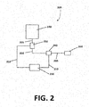
- FIG. 2 illustrates another embodiment of the sampling system.
- FIG. 2 is similar to FIG. 1 , but with the addition of a control module 250, that is in communication with the at least one aseptic sampling system 230 and a sample-directing manifold 240, through line 252.
- FIG. 3 illustrates a schematic of one embodiment of the sample-directing manifold 300.
- the sample-directing manifold 340 of FIG. 3 includes four sample inlets 305, each sample inlet 305 having a sample outlet valve 315 and a waste outlet valve 317.
- the sample-directing manifold also includes a flushing fluid inlet 307 that is upstream of the first sample outlet valve 315, a sample outlet path 325, and a sample outlet 338 that is downstream of the fourth sample outlet valve 315.
- the sample inlet 305 is located between the corresponding sample outlet valve 315 and waste outlet valve 317.
- the sample-directing manifold also includes a waste outlet path 330, and a waste outlet 335 that is downstream of the last waste outlet valve 317.
- FIG. 4 illustrates an enlarged partial cross-sectional view of a sample outlet valve 415.
- sanitant 455 can flow around the end of valve stem 421.
- Sealing member 423 seals the valve into seat 431.
- sanitant can pass around a portion of the valve stem 421, thereby improving sanitization or sterilization of the sample outlet path 425.
- the waste outlet valves 317 are of a similar design as shown in FIG. 4 , and can be sanitized using a similar procedure.
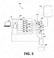
- FIG. 5 shows another embodiment of the sampling system 500.
- FIG. 5 comprises an aseptic source 520, a control module 550, an aseptic sampling valve 530, a sample-directing manifold 540, and an analytical device 560.
- the control module comprises a gas source 551, a plurality of control valves 552, at least two pressure regulators 554, valve 555, and gas filter 557.
- the control module also includes a programmable logic controller (PLC) 558 that communicates with the components in the control module 550.
- PLC programmable logic controller
- a computer interface 590 is also shown for controlling the sampling system 500.
- the aseptic sampling valve 530 comprises valves 532 and a sample pump 535.
- the sample pump 535 is a variable volume sample pump.
- the sample pump 535 is a variable volume reservoir.
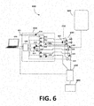
- FIG. 6 shows another embodiment of the sampling system 600.
- FIG. 6 comprises an aseptic source 620, a control module 650, and aseptic sampling valve 630, a sample-directing manifold 640, and an analytical device 660.
- the control module 650 comprises a gas source 651, a plurality of control valves 652, at least three pressure regulators 654, valve 655, gas filter 657, and vacuum pump 659.
- the control module also includes a programmable logic controller (PLC) 658 that communicates with the components in the control module.
- PLC programmable logic controller
- a computer interface 690 is also shown for controlling the sampling system 600.
- the aseptic sampling valve 630 comprises valves 632 and a sample pump 635.
- the sample pump 635 is a variable volume sample pump.
- the sample pump 635 is a variable volume reservoir.
- FIG. 7 illustrates another embodiment of the sampling system 700.
- Sampling system 700 comprises four aseptic sources 720, four aseptic sampling systems 730 in fluid communication with the corresponding aseptic sources 720.
- Sampling system 700 also comprises sample-directing manifold 740, in fluid communication with corresponding sample inlets 705.
- Sampling system 700 also comprises four analytical devices 760, in fluid communication with the sample-directing manifold 740.
- the sampling system 700 can be used to direct sample from each of the aseptic sources 720 to the sample-directing manifold 740 using the aseptic sampling systems 730, and direct the sample to any of the analytical devices 760, using the control module (not shown in FIG. 7 ).
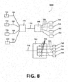
- FIG. 8 illustrates another embodiment of the sampling system 800.
- FIG. 8 shows four aseptic sampling systems 730 in fluid communication sample-directing manifold 740 through corresponding sample inlets 705.
- Sample-directing manifold 740 is in communication with analytical-directing manifold 745.
- Analytical-directing manifold contains four sample-directing valves 748 in fluid communication through lines 725 to four analytical devices 760.
- the sampling system 800 may be configured independently wherein the sample-directing valves 748 may be in fluid communication with only one analytical device 760.
- the sampling system 800 may be configured independently wherein sample-directing valves 748 may be in fluid communication with two or more analytical devices 760.
- the sanitant is any fluid that can sanitize, disinfect, or sterilize the sampling module.
- the sanitant can be a liquid, a gas, or a combination thereof.
- Sanitants include steam, ethylene oxide, glutaraldehyde, formaldehyde, formalin, chlorine gas, hypochlorite, bromine, hypobromite, iodine, hypoiodite, bromine chloride, chlorine dioxide, ozone, hydrogen peroxide, monochloramine, dichloramine, trichloramine, quaternary ammonium salts, ethanol, 70% ethanol/water, isopropanol, 70% isopropanol/water, peroxyacetic acid, and peracetic acid.
- the sanitant is steam.
- the sanitant is ethylene oxide.
- the sanitant is glutaraldehyde.
- the sanitant is ethanol.
- the sanitant is a mixture of ethanol and water, such as 70% ethanol/water.
- the gas may be air, nitrogen, or any gas appropriate to purge the sanitant and sample from the sampling module.
- the gas is filtered through an appropriate filter to remove contaminants that may affect the aseptic nature of the samples.
- the gas is nitrogen.
- the gas is air.
- the sample outlet valve 415 comprises a valve stem 421, a sealing member 423, and a seat 431.
- FIG. 4 illustrates that valve stem 421 tapers at the end to form sealing member 423.
- the tip of the valve stem can extend at an angle ( ⁇ in FIG. 4 ) of greater than 50 degrees from the body of the valve stem 421, in another embodiment the taper is an angle of greater than 60 degrees, in another embodiment the taper is an angle of greater than 70 degrees, and in another embodiment the taper is an angle of about 80 degrees.
- sealing member 423 can be formed of a material that has a lower yield strength than the material of the seat 431, into which sealing member 423 extends.
- sealing member 423 can be made of metals, thermoplastic polymers, such as polyether-ether ketone (PEEK), polyether imide (PEI), polyphenylsulfone (PPSU), polysulfone (PSU), or combinations of these.
- PEEK polyether-ether ketone
- PEI polyether imide
- PPSU polyphenylsulfone
- PSU polysulfone
- sealing member 423 is made from creep resistant metals, such as stainless steel, titanium, nickel, brass, and anodized aluminum; or high temperature thermoplastic polymers such as PEEK, or PPSU (also known as Radel®).
- the seat 431 can be made from a more flexible material, such as silicone rubber, polytetrafluoroethylene (PTFE, also known as Teflon®), perfluroalkoxy (PFA), ethylene tetrafluoroethylene (ETFE), high density polyethylene (HDPE), high density polypropylene (HDPP), perfluroalkoxy (PFA, also known as Viton®), and combinations thereof.
- PTFE polytetrafluoroethylene
- PFA perfluroalkoxy
- ETFE ethylene tetrafluoroethylene
- HDPE high density polyethylene
- HDPP high density polypropylene
- PFA perfluroalkoxy
- Viton® perfluroalkoxy
- the valve stem 421 and the sealing member 423 are selected from metals, PEEK, PPSU, PEI, and mixtures thereof. Suitable metals include stainless steel, titanium, nickel, brass, and anodized aluminum.
- the seat is selected from PFA, PTFE,
- the sealing member 423 is selected from PEEK, PPSU, and PEI
- the seat 431 material is selected from PTFE, Teflon®, ETFE, HDPE, HDPP, PFA, due to their relatively chemically inert behavior.
- the sealing member and seat are arranged to form a variable sealing area when the sealing member and seat are in contact, causing the seat 431 material to deform until the stress on the materials at the seal is within the elastic modulus of the seat material, allowing a good seal even with relatively wide tolerances on the angles of the seat 431 and sealing member 423.
- sealing member 423 is formed of a higher yield strength material, such as a polymeric material, such as PTFE, PFA, ETFE, HDPE, HDPP, etc., while the seat 431 is formed of a more lower yield strength material, such as thermoplastic polymers (PEEK, PEI, PPSU, PSU, etc.), metals, or combinations or these materials.
- sealing member 423 can extrude into the seat 431 to form a tight seal.
- sealing member 423 and seat 431 can be cone shaped and may be inversely shaped such that the cone seat 431 comprises a hollow cone into which the cone shaped member 423 may fit.
- the sealing member 423 can have a steeper cone shape than the hollow cone seat 431, thereby allowing sealing member 423 to extrude into the seat 431 to form a positive seal.
- the heat up and cool down times associated with those parts can be faster than the times associated with other materials, such as steel or other metals.
- the sealing member and valve stem can be formed of the same polymeric material, which can further improve operation by reducing complexities of manufacturing and permitting the sealing member and valve stem component to be more compact.
- the sample-directing manifold comprises 2 module inlets and associated sample outlet valves and waste outlet valves. In another embodiment, the sample-directing manifold comprises 3 module inlets and associated sample outlet valves and waste outlet valves. In yet another embodiment, the sample-directing manifold comprises 4 module inlets and associated sample outlet valves and waste outlet valves. In still another embodiment, at least two sample-directing manifolds are combined to one or more analytical devices or other destinations.
- the analytical device may be a pH meter, a dissolved oxygen probe, an osmometer, high-performance liquid chromatograph (HPLC), a conductivity meter, a gas chromatograph, a mass spectrometer, ion chromatography, dielectric spectroscopy, microscopy, quantitative visualization tools, focused beam reflectance measurements (FBRM), particle vision and measurement (PVM) devices, a turbidity meter, reduction-oxidation probes, a flow cytometer, Raman/NIR spectroscopy, automated hemocytometer, electro-rotation, electrophoresis, dielectrophoresis, fluorescent activated cell sorting (FACS), or other analytical instruments designed to measure the properties of the aseptic fluid.
- HPLC high-performance liquid chromatograph
- HPLC high-performance liquid chromatograph
- HPLC high-performance liquid chromatograph
- HPLC high-performance liquid chromatograph
- HPLC high-performance liquid chromatograph
- HPLC high-performance liquid chromatograph
- HPLC high-performance liquid
- the sample-directing manifold comprises, consists of, or essentially consists of, a plurality of sample inlets, wherein each sample inlet is in fluid communication with a respective sample outlet valve and a respective waste outlet valve, a sample outlet path in fluid communication with each said respective sample outlet valve, and a waste outlet path in fluid communication with each said respective waste outlet valve.
- the respective waste outlet valve and each of the respective sample outlet valves may be configured independently so that only one of said plurality of sample inlets may be in fluid communication with said sample outlet path.
- the sample-directing manifold as disclosed immediately above further comprise a flushing fluid inlet in fluid communication with said sample outlet path.
- the sample-directing manifold the above embodiments are made from a body having internal channels defining said plurality of sample inlets, said sample outlet path, and said waste outlet path.
- the above embodiments may comprise the body having channels for each of said respective sample outlet valves and each of said respective waste outlet valves.
- the sampling system for collecting a fluid sample from an enclosed container comprises the sample-directing manifold of any one of the previous disclosed embodiments.
- the sampling system disclosed immediately above further comprises an aseptic sampling valve.
- the aseptic sampling valve in the preceding embodiments comprises a variable volume reservoir.
- sampling systems described above also may further comprise an control module in communication with said sample-directing manifold and said aseptic sampling valve.
- the sample manifold comprises a plurality of sample inlets, each sample inlet having a sample outlet valve and a waste outlet valve, a sample outlet path, a waste outlet path, a gas inlet valve, a fluid inlet valve, and an outlet path isolation valve, wherein said sample manifold can be configured so that each sample inlet can be connected to said sample outlet path through said sample outlet valve while said outlet path isolation valve is closed, while the other sample inlets are connected to said waste outlet path through said waste outlet valves, and wherein said fluid inlet can be configured to remove said sample from said sample outlet path when said outlet path isolation valve is open so as to direct said fluid to waste, and said gas inlet can be used to remove said fluid from said outlet path when said isolation valve is open, so as to prepare said outlet path for receiving another sample.
- the sampling system for collecting a fluid sample from an enclosed container comprises at least two modules, a control module, and a sampling module, wherein said control module comprises a source of compressed gas, one or more valves for directing compressed gas to the sampling module, and an optional vacuum pump; and the sampling module comprises a sanitizing fluid inlet valve, a gas inlet valve, a sample collection valve, an outlet valve, a variable volume reservoir, and a fluid flow path interconnecting the sanitizing fluid inlet valve, the gas inlet valve, the sample collection valve and the variable volume reservoir.
Landscapes
- Life Sciences & Earth Sciences (AREA)
- Health & Medical Sciences (AREA)
- Chemical & Material Sciences (AREA)
- Engineering & Computer Science (AREA)
- General Health & Medical Sciences (AREA)
- Biochemistry (AREA)
- Bioinformatics & Cheminformatics (AREA)
- Wood Science & Technology (AREA)
- Zoology (AREA)
- Organic Chemistry (AREA)
- Biomedical Technology (AREA)
- Immunology (AREA)
- General Physics & Mathematics (AREA)
- Analytical Chemistry (AREA)
- Pathology (AREA)
- Physics & Mathematics (AREA)
- Molecular Biology (AREA)
- Biotechnology (AREA)
- Genetics & Genomics (AREA)
- General Engineering & Computer Science (AREA)
- Sustainable Development (AREA)
- Microbiology (AREA)
- Hydrology & Water Resources (AREA)
- Clinical Laboratory Science (AREA)
- Sampling And Sample Adjustment (AREA)
Applications Claiming Priority (4)
| Application Number | Priority Date | Filing Date | Title |
|---|---|---|---|
| US201361832101P | 2013-06-06 | 2013-06-06 | |
| US201461933806P | 2014-01-30 | 2014-01-30 | |
| EP14732491.7A EP3004318B1 (de) | 2013-06-06 | 2014-05-19 | Aseptisches probenentnahmemodul und verteiler |
| PCT/US2014/038614 WO2014197192A1 (en) | 2013-06-06 | 2014-05-19 | Aseptic sampling module and manifold |
Related Parent Applications (2)
| Application Number | Title | Priority Date | Filing Date |
|---|---|---|---|
| EP14732491.7A Division EP3004318B1 (de) | 2013-06-06 | 2014-05-19 | Aseptisches probenentnahmemodul und verteiler |
| PCT/US2014/038614 Previously-Filed-Application WO2014197192A1 (en) | 2013-06-06 | 2014-05-19 | Aseptic sampling module and manifold |
Publications (1)
| Publication Number | Publication Date |
|---|---|
| EP3666878A1 true EP3666878A1 (de) | 2020-06-17 |
Family
ID=50981867
Family Applications (2)
| Application Number | Title | Priority Date | Filing Date |
|---|---|---|---|
| EP14732491.7A Active EP3004318B1 (de) | 2013-06-06 | 2014-05-19 | Aseptisches probenentnahmemodul und verteiler |
| EP19201814.1A Pending EP3666878A1 (de) | 2013-06-06 | 2014-05-19 | Aseptisches probenentnahmemodul und verteiler |
Family Applications Before (1)
| Application Number | Title | Priority Date | Filing Date |
|---|---|---|---|
| EP14732491.7A Active EP3004318B1 (de) | 2013-06-06 | 2014-05-19 | Aseptisches probenentnahmemodul und verteiler |
Country Status (4)
| Country | Link |
|---|---|
| US (2) | US20160025601A1 (de) |
| EP (2) | EP3004318B1 (de) |
| ES (1) | ES2765298T3 (de) |
| WO (1) | WO2014197192A1 (de) |
Families Citing this family (10)
| Publication number | Priority date | Publication date | Assignee | Title |
|---|---|---|---|---|
| EP3207728B1 (de) * | 2014-10-17 | 2021-05-19 | Samsung Electronics Co., Ltd. | Verfahren und systeme zur ermöglichung von kanalmessung eines nicht lizenzierten trägers in zellularen systemen auf nicht lizenzierten bändern |
| US20180137218A1 (en) * | 2016-11-11 | 2018-05-17 | General Electric Company | Systems and methods for similarity-based information augmentation |
| USD878626S1 (en) | 2018-06-21 | 2020-03-17 | Merck Chemicals And Life Science Ab | Expansion trigger for a sampling device |
| USD878628S1 (en) | 2018-06-21 | 2020-03-17 | Merck Chemicals And Life Science Ab | Expansion trigger and holder assembly for a sampling system |
| USD889687S1 (en) | 2018-06-21 | 2020-07-07 | Merck Chemicals And Life Science Ab | Expansion triggers and holder assembly for a sampling system |
| USD878627S1 (en) | 2018-06-21 | 2020-03-17 | Merck Chemicals And Life Science Ab | Expansion trigger and holder assembly for a sampling system |
| CA3148966A1 (en) * | 2019-09-02 | 2021-03-11 | Ashley Jensen | Sampler |
| WO2021097281A1 (en) | 2019-11-15 | 2021-05-20 | Lonza Ltd | Process and system for producing an inoculum |
| EP4273260A4 (de) * | 2021-02-02 | 2024-07-17 | TERUMO Kabushiki Kaisha | Probenahmeverfahren |
| US12168761B2 (en) * | 2022-05-24 | 2024-12-17 | Ark Biotech Inc. | Auxiliary manifold for a bioreactor |
Citations (4)
| Publication number | Priority date | Publication date | Assignee | Title |
|---|---|---|---|---|
| US6332349B1 (en) * | 1998-06-15 | 2001-12-25 | L'air Liquide, Societe Anonyme Pour L'etude Et L'exploitation Des Procedes Georges Claude | Installation for analyzing an atmosphere |
| US20050217351A1 (en) * | 2004-04-06 | 2005-10-06 | Kreck Jeffery W | Sequencing and averaging multiple sample system |
| US20120137793A1 (en) * | 2010-12-03 | 2012-06-07 | Alfa Wassermann, Inc. | Automated aseptic sampling workstation and sample collection devices therefore |
| WO2012087235A1 (en) * | 2010-12-21 | 2012-06-28 | Delaval Holding Ab | Milk sampling |
Family Cites Families (5)
| Publication number | Priority date | Publication date | Assignee | Title |
|---|---|---|---|---|
| EP2724736B1 (de) * | 2006-04-14 | 2022-06-08 | DEKA Products Limited Partnership | Kassette mit eingehauster pumpe |
| JP2010535339A (ja) * | 2007-08-02 | 2010-11-18 | ミリポア・コーポレイション | 流体試料を処理するシステムおよび装置 |
| US8549934B2 (en) * | 2008-03-25 | 2013-10-08 | Flownamics Analytical Instruments, Inc. | Segmented online sampling apparatus and method of use |
| US20100043883A1 (en) * | 2008-06-25 | 2010-02-25 | Groton Biosystems, Llc | System and method for automated sterile sampling of fluid from a vessel |
| EP4151716A1 (de) * | 2011-05-06 | 2023-03-22 | EMD Millipore Corporation | Automatisches aseptisches probenentnahmeventil zur probenentnahme aus geschlossenen behältern |
-
2014
- 2014-05-19 US US14/774,122 patent/US20160025601A1/en not_active Abandoned
- 2014-05-19 EP EP14732491.7A patent/EP3004318B1/de active Active
- 2014-05-19 EP EP19201814.1A patent/EP3666878A1/de active Pending
- 2014-05-19 WO PCT/US2014/038614 patent/WO2014197192A1/en not_active Ceased
- 2014-05-19 ES ES14732491T patent/ES2765298T3/es active Active
-
2025
- 2025-10-23 US US19/367,733 patent/US20260049905A1/en active Pending
Patent Citations (4)
| Publication number | Priority date | Publication date | Assignee | Title |
|---|---|---|---|---|
| US6332349B1 (en) * | 1998-06-15 | 2001-12-25 | L'air Liquide, Societe Anonyme Pour L'etude Et L'exploitation Des Procedes Georges Claude | Installation for analyzing an atmosphere |
| US20050217351A1 (en) * | 2004-04-06 | 2005-10-06 | Kreck Jeffery W | Sequencing and averaging multiple sample system |
| US20120137793A1 (en) * | 2010-12-03 | 2012-06-07 | Alfa Wassermann, Inc. | Automated aseptic sampling workstation and sample collection devices therefore |
| WO2012087235A1 (en) * | 2010-12-21 | 2012-06-28 | Delaval Holding Ab | Milk sampling |
Also Published As
| Publication number | Publication date |
|---|---|
| EP3004318A1 (de) | 2016-04-13 |
| ES2765298T3 (es) | 2020-06-08 |
| EP3004318B1 (de) | 2019-10-09 |
| US20160025601A1 (en) | 2016-01-28 |
| US20260049905A1 (en) | 2026-02-19 |
| WO2014197192A1 (en) | 2014-12-11 |
Similar Documents
| Publication | Publication Date | Title |
|---|---|---|
| US20260049905A1 (en) | Aseptic sampling module and manifold | |
| US11906402B2 (en) | Automatic aseptic sampling valve for sampling from enclosed containers | |
| US9389151B2 (en) | Fixed volume aseptic sampling valve for sampling from enclosed containers | |
| US8431089B2 (en) | Process analysis system with sterile sampling of mechanically-sensitive material from a bioreactor | |
| US20200017818A1 (en) | Systems and methods for producing bioproducts | |
| US9322749B2 (en) | Automatic sampling system for sampling from enclosed containers | |
| US20100047122A1 (en) | System and method for automated sterile sampling of fluid from a vessel | |
| TWI414371B (zh) | 用於物質處理收容器之排放連接頭 | |
| WO1996008556A1 (de) | NEUES PROBENAHMESYSTEM FÜR DIE BIOPROZEssANALYTIK | |
| US20100043883A1 (en) | System and method for automated sterile sampling of fluid from a vessel | |
| DE102010001876A1 (de) | Sondeneinrichtung zum Messen einer Messgröße eines in einem Prozessbehälter enthaltenen Messmediums | |
| US20260071938A1 (en) | Sampling system with a replaceable cassette assembly and methods of using the same | |
| JP2021019519A (ja) | 無菌サンプリング装置 | |
| EP4159836A1 (de) | Filterpatrone und mikrobielles testverfahren | |
| KR20220121895A (ko) | 세포 제거 시스템을 위한 여과 시스템 및 그 사용 방법 | |
| CA3138722C (en) | Sampling system with a replaceable cassette assembly and methods of using the same | |
| US11957809B2 (en) | Process challenge device for evaluation of contamination forming and removal processes inside of hollow channels and methods for contamination evaluation | |
| WO2003039961A2 (en) | Sampling manifold | |
| DE102023116604A1 (de) | Inline-Sensoren für Prozessanwendung und Verfahren zur Inbetriebnahme der Inline-Sensoren |
Legal Events
| Date | Code | Title | Description |
|---|---|---|---|
| PUAI | Public reference made under article 153(3) epc to a published international application that has entered the european phase |
Free format text: ORIGINAL CODE: 0009012 |
|
| STAA | Information on the status of an ep patent application or granted ep patent |
Free format text: STATUS: THE APPLICATION HAS BEEN PUBLISHED |
|
| AC | Divisional application: reference to earlier application |
Ref document number: 3004318 Country of ref document: EP Kind code of ref document: P |
|
| AK | Designated contracting states |
Kind code of ref document: A1 Designated state(s): AL AT BE BG CH CY CZ DE DK EE ES FI FR GB GR HR HU IE IS IT LI LT LU LV MC MK MT NL NO PL PT RO RS SE SI SK SM TR |
|
| STAA | Information on the status of an ep patent application or granted ep patent |
Free format text: STATUS: REQUEST FOR EXAMINATION WAS MADE |
|
| 17P | Request for examination filed |
Effective date: 20201216 |
|
| RBV | Designated contracting states (corrected) |
Designated state(s): AL AT BE BG CH CY CZ DE DK EE ES FI FR GB GR HR HU IE IS IT LI LT LU LV MC MK MT NL NO PL PT RO RS SE SI SK SM TR |
|
| RAP1 | Party data changed (applicant data changed or rights of an application transferred) |
Owner name: EMD MILLIPORE CORPORATION |
|
| P01 | Opt-out of the competence of the unified patent court (upc) registered |
Effective date: 20230602 |
|
| STAA | Information on the status of an ep patent application or granted ep patent |
Free format text: STATUS: EXAMINATION IS IN PROGRESS |
|
| 17Q | First examination report despatched |
Effective date: 20231127 |