EP3666709A1 - Brake device, method for testing the brake device, and elevator system - Google Patents
Brake device, method for testing the brake device, and elevator system Download PDFInfo
- Publication number
- EP3666709A1 EP3666709A1 EP19215015.9A EP19215015A EP3666709A1 EP 3666709 A1 EP3666709 A1 EP 3666709A1 EP 19215015 A EP19215015 A EP 19215015A EP 3666709 A1 EP3666709 A1 EP 3666709A1
- Authority
- EP
- European Patent Office
- Prior art keywords
- moving member
- retracted position
- elevator
- attracted
- brake device
- Prior art date
- Legal status (The legal status is an assumption and is not a legal conclusion. Google has not performed a legal analysis and makes no representation as to the accuracy of the status listed.)
- Pending
Links
- 238000012360 testing method Methods 0.000 title claims abstract description 82
- 238000000034 method Methods 0.000 title claims abstract description 23
- 238000012423 maintenance Methods 0.000 description 2
- 238000012986 modification Methods 0.000 description 2
- 230000004048 modification Effects 0.000 description 2
- 230000005483 Hooke's law Effects 0.000 description 1
- 238000004891 communication Methods 0.000 description 1
- 230000003203 everyday effect Effects 0.000 description 1
- 238000002474 experimental method Methods 0.000 description 1
Images


Classifications
-
- B—PERFORMING OPERATIONS; TRANSPORTING
- B66—HOISTING; LIFTING; HAULING
- B66B—ELEVATORS; ESCALATORS OR MOVING WALKWAYS
- B66B5/00—Applications of checking, fault-correcting, or safety devices in elevators
- B66B5/0006—Monitoring devices or performance analysers
- B66B5/0018—Devices monitoring the operating condition of the elevator system
- B66B5/0025—Devices monitoring the operating condition of the elevator system for maintenance or repair
-
- F—MECHANICAL ENGINEERING; LIGHTING; HEATING; WEAPONS; BLASTING
- F16—ENGINEERING ELEMENTS AND UNITS; GENERAL MEASURES FOR PRODUCING AND MAINTAINING EFFECTIVE FUNCTIONING OF MACHINES OR INSTALLATIONS; THERMAL INSULATION IN GENERAL
- F16D—COUPLINGS FOR TRANSMITTING ROTATION; CLUTCHES; BRAKES
- F16D66/00—Arrangements for monitoring working conditions, e.g. wear, temperature
- F16D66/02—Apparatus for indicating wear
- F16D66/021—Apparatus for indicating wear using electrical detection or indication means
- F16D66/022—Apparatus for indicating wear using electrical detection or indication means indicating that a lining is worn to minimum allowable thickness
-
- B—PERFORMING OPERATIONS; TRANSPORTING
- B66—HOISTING; LIFTING; HAULING
- B66B—ELEVATORS; ESCALATORS OR MOVING WALKWAYS
- B66B5/00—Applications of checking, fault-correcting, or safety devices in elevators
- B66B5/0006—Monitoring devices or performance analysers
- B66B5/0037—Performance analysers
-
- B—PERFORMING OPERATIONS; TRANSPORTING
- B66—HOISTING; LIFTING; HAULING
- B66B—ELEVATORS; ESCALATORS OR MOVING WALKWAYS
- B66B5/00—Applications of checking, fault-correcting, or safety devices in elevators
-
- B—PERFORMING OPERATIONS; TRANSPORTING
- B66—HOISTING; LIFTING; HAULING
- B66B—ELEVATORS; ESCALATORS OR MOVING WALKWAYS
- B66B5/00—Applications of checking, fault-correcting, or safety devices in elevators
- B66B5/02—Applications of checking, fault-correcting, or safety devices in elevators responsive to abnormal operating conditions
- B66B5/16—Braking or catch devices operating between cars, cages, or skips and fixed guide elements or surfaces in hoistway or well
-
- B—PERFORMING OPERATIONS; TRANSPORTING
- B66—HOISTING; LIFTING; HAULING
- B66D—CAPSTANS; WINCHES; TACKLES, e.g. PULLEY BLOCKS; HOISTS
- B66D5/00—Braking or detent devices characterised by application to lifting or hoisting gear, e.g. for controlling the lowering of loads
- B66D5/02—Crane, lift hoist, or winch brakes operating on drums, barrels, or ropes
- B66D5/06—Crane, lift hoist, or winch brakes operating on drums, barrels, or ropes with radial effect
- B66D5/08—Crane, lift hoist, or winch brakes operating on drums, barrels, or ropes with radial effect embodying blocks or shoes
-
- B—PERFORMING OPERATIONS; TRANSPORTING
- B66—HOISTING; LIFTING; HAULING
- B66D—CAPSTANS; WINCHES; TACKLES, e.g. PULLEY BLOCKS; HOISTS
- B66D5/00—Braking or detent devices characterised by application to lifting or hoisting gear, e.g. for controlling the lowering of loads
- B66D5/02—Crane, lift hoist, or winch brakes operating on drums, barrels, or ropes
- B66D5/24—Operating devices
- B66D5/30—Operating devices electrical
-
- F—MECHANICAL ENGINEERING; LIGHTING; HEATING; WEAPONS; BLASTING
- F16—ENGINEERING ELEMENTS AND UNITS; GENERAL MEASURES FOR PRODUCING AND MAINTAINING EFFECTIVE FUNCTIONING OF MACHINES OR INSTALLATIONS; THERMAL INSULATION IN GENERAL
- F16D—COUPLINGS FOR TRANSMITTING ROTATION; CLUTCHES; BRAKES
- F16D66/00—Arrangements for monitoring working conditions, e.g. wear, temperature
-
- F—MECHANICAL ENGINEERING; LIGHTING; HEATING; WEAPONS; BLASTING
- F16—ENGINEERING ELEMENTS AND UNITS; GENERAL MEASURES FOR PRODUCING AND MAINTAINING EFFECTIVE FUNCTIONING OF MACHINES OR INSTALLATIONS; THERMAL INSULATION IN GENERAL
- F16D—COUPLINGS FOR TRANSMITTING ROTATION; CLUTCHES; BRAKES
- F16D66/00—Arrangements for monitoring working conditions, e.g. wear, temperature
- F16D66/02—Apparatus for indicating wear
- F16D66/021—Apparatus for indicating wear using electrical detection or indication means
- F16D66/028—Apparatus for indicating wear using electrical detection or indication means with non-electrical sensors or signal transmission, e.g. magnetic, optical
-
- F—MECHANICAL ENGINEERING; LIGHTING; HEATING; WEAPONS; BLASTING
- F16—ENGINEERING ELEMENTS AND UNITS; GENERAL MEASURES FOR PRODUCING AND MAINTAINING EFFECTIVE FUNCTIONING OF MACHINES OR INSTALLATIONS; THERMAL INSULATION IN GENERAL
- F16D—COUPLINGS FOR TRANSMITTING ROTATION; CLUTCHES; BRAKES
- F16D66/00—Arrangements for monitoring working conditions, e.g. wear, temperature
- F16D2066/003—Position, angle or speed
Definitions
- the present disclosure relates to the field of elevators, and in particular to a method for testing an elevator brake device, a brake device, and an elevator system.
- a normally closed brake device In an elevator system, a normally closed brake device is usually used.
- the brake device includes a fixed member and a moving member, and an elastic member such as a spring is disposed between the fixed member and the moving member to tend to hold the moving member at a braking position.
- an elastic member such as a spring is disposed between the fixed member and the moving member to tend to hold the moving member at a braking position.
- the moving member When a coil on the fixed member is energized, the moving member will be attracted by a magnetic field generated by the coil to overcome an elastic force of the elastic member to move to a retracted position, thereby releasing a braking member, such as a brake disc or a brake wheel, and enabling the elevator to operate.
- a friction plate on the moving member of the elevator will be gradually worn out.
- a feeler gauge is used to manually detect an air gap between the moving member and the fixed member to estimate the degree of wear of the friction plate.
- An object of the present disclosure is to solve or at least alleviate the problems in the prior art.
- a brake device for an elevator which includes:
- the controller is configured to implement the test mode periodically.
- the controller confirms that an elevator car has stopped and is unloaded before implementing the test mode.
- the controller resumes normal operation of the elevator in a case that the moving member has been attracted to the retracted position, and sends prompt information and/or controls the elevator to stop operating in a case that the moving member fails to be attracted to the retracted position.
- the test current I 2 is 50%-95% of the operating current I 1 .
- the controller provides the test current I 2 less than the operating current I 1 in the test mode by lowering a supply voltage.
- the controller provides a first test current I 21 less than the operating current to the coil in the test mode and determines whether the moving member has been attracted to the retracted position; in a case that the moving member has been attracted to the retracted position, the controller resumes normal operation of the elevator, and in a case that the moving member fails to be attracted to the retracted position, the controller sends prompt information and provides a second test current I 22 to the coil, wherein I 21 ⁇ I 22 ⁇ I 1 , and the controller determines whether the moving member has been attracted to the retracted position; in a case that the moving member has been attracted to the retracted position, the controller resumes normal operation of the elevator, and in a case that the moving member fails to be attracted to the retracted position, the controller controls the elevator to stop operating.
- an elevator system is further provided, which includes the brake device described in various embodiments.
- a method for testing an elevator brake device which includes:
- the method further includes implementing the test mode in a case that an elevator car has stopped and is unloaded.
- the method further includes resuming normal operation of the elevator in a case that the moving member has been attracted to the retracted position, and sending prompt information and/or controlling the elevator to stop operating in a case that the moving member fails to be attracted to the retracted position.
- the method further includes setting the test current I 2 to be 50%-95% of the operating current I 1 .
- the method further includes providing the test current I 2 less than the operating current I 1 in the test mode by lowering a supply voltage.
- the method further includes: providing a first test current I 21 less than the operating current to the coil in the test mode and determining whether the moving member has been attracted to the retracted position; resuming normal operation of the elevator in a case that the moving member has been attracted to the retracted position; sending prompt information in a case that the moving member fails to be attracted to the retracted position, providing a second test current I 22 to the coil by the controller, wherein I 21 ⁇ I 22 ⁇ I 1 , and determining whether the moving member has been attracted to the retracted position; resuming normal operation of the elevator in a case that the moving member has been attracted to the retracted position, and controlling the elevator to stop operating in a case that the moving member fails to be attracted to the retracted position.
- orientation terms as upper, lower, left, right, front, rear, front side, back side, top, bottom or the like that are mentioned or may be mentioned in this description are defined with respect to the configurations shown in the individual drawings. They are relative concepts and thus possibly vary according to their different locations and different usage states. Therefore, these or other orientation terms shall not be interpreted as limiting terms.
- the brake device mainly includes: a fixed member 1, a moving member 2 and a braking member 3.
- the fixed member 1 is for example fixedly installed in a machine room, and the moving member 2 may include a plate body 21, a friction plate holder 22, and a friction plate 23.
- the moving member 2 is movable between a braking position shown in FIG. 1 and a retracted position shown in FIG. 2 .
- a movement of the moving member 2 is guided by pins 71 and 72.
- the friction plate 23 of the moving member 2 is in contact with the braking member 3 and provides a braking force to the braking member 3.
- the braking member 3 may for example be a wheel or a disc, which may be directly or indirectly connected to a traction machine which provides power to the elevator.
- the moving member 2 is engaged with the braking member 3 and provides a braking force by friction, thereby stopping the elevator.
- the friction plate 23 With the use of the elevator brake device, the friction plate 23 will be gradually worn, and the air gap G therefore will gradually increase.
- the brake device is a normally closed brake device, wherein elastic members 51 and 52 are disposed between the moving member 2 and the fixed member 1, and the elastic members are intended to tend to push the moving member 2 toward the braking position. Due to the elastic members 51 and 52, the brake device will also function when the elevator is unexpectedly powered off.
- coils 61 and 62 are disposed in the fixed member 1, and they will generate a magnetic field when energized, so as to attract the moving member 2 to move toward the retracted position.
- the brake device further includes a controller that provides an operating current I 1 to the coils 61 and 62 during operation of the elevator to operate the brake device to function, such as braking or releasing the braking member 3 during normal operation.
- the controller is further configured to be capable of implementing a test mode in which the controller provides a test current I 2 less than the operating current I 1 to the coils 61 and 62 and determines whether the moving member 2 has been attracted to the retracted position.
- the degree of wear of the friction piece 23 of the moving member 2 can be qualitatively tested based on whether the moving member 2 can be attracted in case of reduced current.
- FIG. 3 In the case of the normal operating current I 1 , as the friction plate 23 is worn in use, the air gap G between the moving member 2 and the fixed member 1 in the braking state shown in FIG. 1 will gradually increase, and due to the increase of the air gap G, the attracting force of the magnetic field generated by the coils 61 and 62 in the fixed member 1 to the moving member 2 will gradually decrease, as shown in FIG. 3 .
- FIG. 3 On the other hand, as shown in FIG.
- the operating current I 1 is set such that in the case of any air gap G, the attracting force of the coils 61 and 62 of the fixed member 1 to the moving member 2 is significantly greater than the elastic resultant force of the elastic member 51 and 52 to the moving member 2, thereby ensuring that the moving member 2 can be attracted to the retracted position when the coils 61 and 62 are energized.
- the friction plate 23 has been worn to such a degree that the air gap G is greater than the critical value such as 0.8mm, then in the test mode, the attracting force that the moving member 2 is subjected to will be less than the elastic resultant force, so the moving member 2 cannot be attracted to the retracted position. Therefore, it can be determined whether the friction piece is worn to the degree that the air gap is greater than the critical value based on whether the moving piece 2 is attracted to the retracted position in the test mode.
- the test current I 2 may depend on the critical value of the air gap G.
- the test current I 2 is obtained by calculation or experiment, and the critical value of the air gap G may be further set based on theoretical calculation and/or practical experience.
- the test current I 2 is set to be 50%-95% of the operating current I 1 ; in some embodiments, the test current I 2 is set to be 60%-90% of the operating current I 1 ; and in some embodiments, the test current I 2 is set to be 70%-85% of the operating current I 1 , and so on.
- the controller may provide the test current I 2 less than the operating current I 1 by reducing the voltage supplied to the coils in the test mode; for example, an additional resistor may be added to the circuit to reduce the voltage supplied to the coils.
- the controller is configured to periodically implement the test mode. For example, the controller may be configured to implement the test mode every day, every week, or every other certain number of days. In some embodiments, the controller is configured to implement the test mode at a particular time, for example during a period of low elevator load, such as implementing the test mode in the early hours of the morning. In some embodiments, the controller is configured to first confirm whether the elevator car is in a stopped and unloaded state when the test time comes. If the elevator car is not unloaded, then the elevator car will not undertake new tasks after the current task is completed. For example, it will stop at a predetermined floor directly to implement the test mode.
- an elevator system is further provided by the present disclosure, which includes the brake device described in various embodiments of the present disclosure.
- the method may include: implementing a test mode when a moving member is in a braking position; providing a test current I 2 to a coil in a fixed member, the test current I 2 being less than an operating current I 1 provided to the coil when the elevator is in normal operation; and determining whether the moving member is capable of being attracted to a retracted position.
- the method further includes implementing the test mode in a case that an elevator car has stopped and is unloaded.
- the method further includes resuming normal operation of the elevator in a case that the moving member has been attracted to the retracted position, and sending prompt information in a case that the moving member fails to be attracted to the retracted position.
- the prompt information is sent to maintenance personnel or elevator management personnel via wireless communication to prompt maintenance, such as replacing the friction plate.
- the elevator may be controlled to stop operating, and prompt information may be sent.
- the method further includes providing the test current I 2 less than the operating current I 1 by lowering a supply voltage.
- the method further includes: providing a first test current I 21 less than the operating current to the coil in the test mode and determining whether the moving member has been attracted to the retracted position; resuming normal operation of the elevator in a case that the moving member has been attracted to the retracted position; and sending prompt information in a case that the moving member fails to be attracted to the retracted position.
- the first test current I 21 may correspond to a situation in which the friction plate needs to be replaced but the elevator can still operate normally for a period of time.
- the controller then provides a second test current I 22 to the coil wherein I 21 ⁇ I 22 ⁇ I 1 , and it is determined whether the moving member has been attracted to the retracted position; normal operation of the elevator is resumed in a case that the moving member has been attracted to the retracted position, and the controller controls the elevator to stop operating in a case that the moving member fails to be attracted to the retracted position.
Landscapes
- Engineering & Computer Science (AREA)
- General Engineering & Computer Science (AREA)
- Mechanical Engineering (AREA)
- Maintenance And Inspection Apparatuses For Elevators (AREA)
- Elevator Control (AREA)
- Braking Arrangements (AREA)
Abstract
Description
- The present disclosure relates to the field of elevators, and in particular to a method for testing an elevator brake device, a brake device, and an elevator system.
- In an elevator system, a normally closed brake device is usually used. The brake device includes a fixed member and a moving member, and an elastic member such as a spring is disposed between the fixed member and the moving member to tend to hold the moving member at a braking position. When a coil on the fixed member is energized, the moving member will be attracted by a magnetic field generated by the coil to overcome an elastic force of the elastic member to move to a retracted position, thereby releasing a braking member, such as a brake disc or a brake wheel, and enabling the elevator to operate. With the operation of the elevator, a friction plate on the moving member of the elevator will be gradually worn out. Usually, a feeler gauge is used to manually detect an air gap between the moving member and the fixed member to estimate the degree of wear of the friction plate.
- An object of the present disclosure is to solve or at least alleviate the problems in the prior art.
- In one aspect, a brake device for an elevator is provided by the present disclosure, which includes:
- a fixed member;
- a moving member which is movable between a retracted position in which the moving member is adjacent to the fixed member and separate from a braking member, and a braking position in which a friction plate of the moving member contacts the braking member and provides a braking force to the braking member;
- an elastic member connected between the moving member and the fixed member, the elastic member tending to urge the moving member toward the braking position;
- a coil disposed in the fixed member, the coil generating a magnetic field when being energized to attract the moving member to move toward the retracted position; and
- a controller which provides an operating current I1 to the coil when the elevator is in normal operation, wherein the controller is configured to implement a test mode in which the controller provides a test current I2 less than the operating current I1 to the coil and determines whether the moving member has been attracted to the retracted position.
- Optionally, in the brake device, the controller is configured to implement the test mode periodically.
- Optionally, in the brake device, the controller confirms that an elevator car has stopped and is unloaded before implementing the test mode.
- Optionally, in the brake device, in the test mode, the controller resumes normal operation of the elevator in a case that the moving member has been attracted to the retracted position, and sends prompt information and/or controls the elevator to stop operating in a case that the moving member fails to be attracted to the retracted position.
- Optionally, in the brake device, the test current I2 is 50%-95% of the operating current I1.
- Optionally, in the brake device, the controller provides the test current I2 less than the operating current I1 in the test mode by lowering a supply voltage.
- Optionally, in the brake device, the controller provides a first test current I21 less than the operating current to the coil in the test mode and determines whether the moving member has been attracted to the retracted position; in a case that the moving member has been attracted to the retracted position, the controller resumes normal operation of the elevator, and in a case that the moving member fails to be attracted to the retracted position, the controller sends prompt information and provides a second test current I22 to the coil, wherein I21<I22<I1, and the controller determines whether the moving member has been attracted to the retracted position; in a case that the moving member has been attracted to the retracted position, the controller resumes normal operation of the elevator, and in a case that the moving member fails to be attracted to the retracted position, the controller controls the elevator to stop operating.
- According to some aspects, an elevator system is further provided, which includes the brake device described in various embodiments.
- According to some aspects, a method for testing an elevator brake device is further provided, which includes:
- implementing a test mode when a moving member is in a braking position;
- providing a test current I2 to a coil in a fixed member, the test current I2 being less than an operating current I1 provided to the coil when the elevator is in normal operation; and
- determining whether the moving member is capable of being attracted to a retracted position.
- Optionally, the method further includes implementing the test mode in a case that an elevator car has stopped and is unloaded.
- Optionally, the method further includes resuming normal operation of the elevator in a case that the moving member has been attracted to the retracted position, and sending prompt information and/or controlling the elevator to stop operating in a case that the moving member fails to be attracted to the retracted position.
- Optionally, the method further includes setting the test current I2 to be 50%-95% of the operating current I1.
- Optionally, the method further includes providing the test current I2 less than the operating current I1 in the test mode by lowering a supply voltage.
- Optionally, the method further includes: providing a first test current I21 less than the operating current to the coil in the test mode and determining whether the moving member has been attracted to the retracted position; resuming normal operation of the elevator in a case that the moving member has been attracted to the retracted position; sending prompt information in a case that the moving member fails to be attracted to the retracted position, providing a second test current I22 to the coil by the controller, wherein I21<I22<I1, and determining whether the moving member has been attracted to the retracted position; resuming normal operation of the elevator in a case that the moving member has been attracted to the retracted position, and controlling the elevator to stop operating in a case that the moving member fails to be attracted to the retracted position.
- The contents of the present disclosure will become more easily understood with reference to the accompanying drawings. Those skilled in the art can readily appreciate that the drawings are for illustrative purposes only, instead of being intended to limit the scope of protection of the present disclosure. In addition, similar numbers in the drawings are used to indicate similar parts, wherein:
-
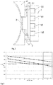
FIG. 1 shows a schematic view of a brake device according to an embodiment of the present disclosure in a braking state; -
FIG. 2 shows a schematic view of the brake device according to the embodiment of the present disclosure in a retracted state; -
FIG. 3 shows a relationship of an air gap and a force in the braking state when different currents are applied; and -
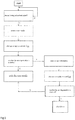
FIGS. 4 and5 show flowcharts of methods according to embodiments of the present disclosure respectively. - It will be readily understood that, based on the technical solutions of the present disclosure, those skilled in the art can propose various alternative embodiments and implementations without departing from the true spirit of the present disclosure. Therefore, the following specific embodiments and the accompanying drawings are merely exemplary description of the technical solutions of the present disclosure, which shall not be deemed as the whole of the present disclosure or as limiting or restricting the technical solutions of the present disclosure.
- Such orientation terms as upper, lower, left, right, front, rear, front side, back side, top, bottom or the like that are mentioned or may be mentioned in this description are defined with respect to the configurations shown in the individual drawings. They are relative concepts and thus possibly vary according to their different locations and different usage states. Therefore, these or other orientation terms shall not be interpreted as limiting terms.
- First, referring to
FIGS. 1 and2 , schematic views of a brake device according to an embodiment of the present disclosure are shown in a braking state and a retracted state respectively. The brake device mainly includes: a fixedmember 1, a movingmember 2 and abraking member 3. Thefixed member 1 is for example fixedly installed in a machine room, and the movingmember 2 may include aplate body 21, afriction plate holder 22, and afriction plate 23. The movingmember 2 is movable between a braking position shown inFIG. 1 and a retracted position shown inFIG. 2 . For example, in the illustrated embodiment, a movement of the movingmember 2 is guided bypins 71 and 72. In the braking position, thefriction plate 23 of the movingmember 2 is in contact with thebraking member 3 and provides a braking force to thebraking member 3. Thebraking member 3 may for example be a wheel or a disc, which may be directly or indirectly connected to a traction machine which provides power to the elevator. The movingmember 2 is engaged with thebraking member 3 and provides a braking force by friction, thereby stopping the elevator. At this point, there is a certain gap G between the movingmember 2 and the fixedmember 1, which is hereinafter referred to as air gap G. With the use of the elevator brake device, thefriction plate 23 will be gradually worn, and the air gap G therefore will gradually increase. When the movingmember 2 is in the retracted position shown inFIG. 2 , the movingmember 2 is close to the fixedmember 1 and separated from thebraking member 3, so that thebraking member 3 is released to allow the movement of the elevator car. In the present embodiment, the brake device is a normally closed brake device, whereinelastic members member 2 and the fixedmember 1, and the elastic members are intended to tend to push the movingmember 2 toward the braking position. Due to theelastic members coils member 1, and they will generate a magnetic field when energized, so as to attract the movingmember 2 to move toward the retracted position. In addition, the brake device further includes a controller that provides an operating current I1 to thecoils braking member 3 during normal operation. In an embodiment of the present disclosure, the controller is further configured to be capable of implementing a test mode in which the controller provides a test current I2 less than the operating current I1 to thecoils member 2 has been attracted to the retracted position. The degree of wear of thefriction piece 23 of the movingmember 2 can be qualitatively tested based on whether the movingmember 2 can be attracted in case of reduced current. - The principle of the brake device according to an embodiment of the present disclosure will be explained with continued reference to
FIG. 3 . As can be seen inFIG. 3 , in the case of the normal operating current I1, as thefriction plate 23 is worn in use, the air gap G between the movingmember 2 and the fixedmember 1 in the braking state shown inFIG. 1 will gradually increase, and due to the increase of the air gap G, the attracting force of the magnetic field generated by thecoils member 1 to the movingmember 2 will gradually decrease, as shown inFIG. 3 . On the other hand, as shown inFIG. 3 , for theelastic members 51 and 52 (which may include springs and buffer mats, etc.), due to the Hooke's law, the elastic resultant force to the movingmember 2 will also decrease as the air gap G increases. In order to ensure the normal operation of the brake device, the operating current I1 is set such that in the case of any air gap G, the attracting force of thecoils member 1 to the movingmember 2 is significantly greater than the elastic resultant force of theelastic member member 2, thereby ensuring that the movingmember 2 can be attracted to the retracted position when thecoils coils friction plate 23 has not yet been worn to such a degree that the air gap G is greater than a critical value such as 0.8mm, then in the test mode, the attracting force that the movingmember 2 is subjected to will be greater than the elastic resultant force, so the movingmember 2 will be attracted to the retracted position, whereas if thefriction plate 23 has been worn to such a degree that the air gap G is greater than the critical value such as 0.8mm, then in the test mode, the attracting force that the movingmember 2 is subjected to will be less than the elastic resultant force, so the movingmember 2 cannot be attracted to the retracted position. Therefore, it can be determined whether the friction piece is worn to the degree that the air gap is greater than the critical value based on whether the movingpiece 2 is attracted to the retracted position in the test mode. - In some embodiments, the test current I2 may depend on the critical value of the air gap G. For example, the test current I2 is obtained by calculation or experiment, and the critical value of the air gap G may be further set based on theoretical calculation and/or practical experience. In some embodiments, the test current I2 is set to be 50%-95% of the operating current I1; in some embodiments, the test current I2 is set to be 60%-90% of the operating current I1; and in some embodiments, the test current I2 is set to be 70%-85% of the operating current I1, and so on. In some embodiments, the controller may provide the test current I2 less than the operating current I1 by reducing the voltage supplied to the coils in the test mode; for example, an additional resistor may be added to the circuit to reduce the voltage supplied to the coils.
- In some embodiments, the controller is configured to periodically implement the test mode. For example, the controller may be configured to implement the test mode every day, every week, or every other certain number of days. In some embodiments, the controller is configured to implement the test mode at a particular time, for example during a period of low elevator load, such as implementing the test mode in the early hours of the morning. In some embodiments, the controller is configured to first confirm whether the elevator car is in a stopped and unloaded state when the test time comes. If the elevator car is not unloaded, then the elevator car will not undertake new tasks after the current task is completed. For example, it will stop at a predetermined floor directly to implement the test mode.
- In another aspect, an elevator system is further provided by the present disclosure, which includes the brake device described in various embodiments of the present disclosure.
- A method of operating the brake device according to an embodiment of the present disclosure will be described with continued reference to
FIG. 4 . The method may include: implementing a test mode when a moving member is in a braking position; providing a test current I2 to a coil in a fixed member, the test current I2 being less than an operating current I1 provided to the coil when the elevator is in normal operation; and determining whether the moving member is capable of being attracted to a retracted position. In some embodiments, the method further includes implementing the test mode in a case that an elevator car has stopped and is unloaded. In some embodiments, the method further includes resuming normal operation of the elevator in a case that the moving member has been attracted to the retracted position, and sending prompt information in a case that the moving member fails to be attracted to the retracted position. For example, the prompt information is sent to maintenance personnel or elevator management personnel via wireless communication to prompt maintenance, such as replacing the friction plate. Alternatively, if it is determined that the thickness of the friction plate of the moving member is reduced to a lower level which may affect the safety of the elevator, the elevator may be controlled to stop operating, and prompt information may be sent. In some embodiments, the method further includes providing the test current I2 less than the operating current I1 by lowering a supply voltage. - With continued reference to
FIG. 5 , in a further embodiment, the method further includes: providing a first test current I21 less than the operating current to the coil in the test mode and determining whether the moving member has been attracted to the retracted position; resuming normal operation of the elevator in a case that the moving member has been attracted to the retracted position; and sending prompt information in a case that the moving member fails to be attracted to the retracted position. The first test current I21 may correspond to a situation in which the friction plate needs to be replaced but the elevator can still operate normally for a period of time. Further, the controller then provides a second test current I22 to the coil wherein I21<I22<I1, and it is determined whether the moving member has been attracted to the retracted position; normal operation of the elevator is resumed in a case that the moving member has been attracted to the retracted position, and the controller controls the elevator to stop operating in a case that the moving member fails to be attracted to the retracted position. - The specific embodiments described above are merely for describing the principle of the present disclosure more clearly, and various components are clearly illustrated or depicted to make it easier to understand the principle of the present disclosure. Those skilled in the art can readily make various modifications or changes to the present disclosure without departing from the scope of the present disclosure. It should be understood that these modifications or changes should be included within the scope of protection of the present disclosure.
Claims (15)
- A brake device, the brake device being used for an elevator and comprising.
a fixed member;
a moving member which is movable between a retracted position in which the moving member is adjacent to the fixed member and separate from a braking member, and a braking position in which a friction plate of the moving member contacts the braking member and provides a braking force to the braking member;
an elastic member connected between the moving member and the fixed member, the elastic member tending to urge the moving member toward the braking position;
a coil disposed in the fixed member, the coil generating a magnetic field when being energized to attract the moving member to move toward the retracted position; and
a controller which provides an operating current to the coil when the elevator is in normal operation, wherein the controller is configured to implement a test mode in which the controller provides a test current less than the operating current to the coil and determines whether the moving member has been attracted to the retracted position. - The brake device according to claim 1, wherein the controller is configured to implement the test mode periodically.
- The brake device according to claim 1 or 2, wherein the controller confirms that an elevator car has stopped and unloaded before implementing the test mode.
- The brake device according to any preceding claim, wherein in the test mode, the controller resumes normal operation of the elevator in a case that the moving member has been attracted to the retracted position, and sends prompt information and/or controls the elevator to stop operating in a case that the moving member fails to be attracted to the retracted position.
- The brake device according to any preceding claim, wherein the test current is 50%-95% of the operating current.
- The brake device according to any preceding claim, wherein the controller provides the test current less than the operating current in the test mode by lowering a supply voltage.
- The brake device according to any preceding claim, wherein the controller provides a first test current less than the operating current to the coil in the test mode and determines whether the moving member has been attracted to the retracted position; in a case that the moving member has been attracted to the retracted position, the controller resumes normal operation of the elevator, and in a case that the moving member fails to be attracted to the retracted position, the controller sends prompt information and provides a second test current to the coil, wherein the first test current < the second test current < the operating current, and the controller determines whether the moving member has been attracted to the retracted position; in a case that the moving member has been attracted to the retracted position, the controller resumes normal operation of the elevator, and in a case that the moving member fails to be attracted to the retracted position, the controller controls the elevator to stop operating.
- An elevator system, comprising the brake device according to any one of claims 1 to 7.
- A method for testing a brake device, comprising:implementing a test mode when a moving member is in a braking position;providing a test current to a coil in a fixed member, the test current being less than an operating current provided to the coil when the elevator is in normal operation; anddetermining whether the moving member is capable of being attracted to a retracted position.
- The method according to claim 9, further comprising implementing the test mode in a case that an elevator car has stopped and is unloaded.
- The method according to claim 9 or 10, further comprising resuming normal operation of the elevator in a case that the moving member has been attracted to the retracted position, and sending prompt information and/or controlling the elevator to stop operating in a case that the moving member fails to be attracted to the retracted position.
- The method according to any of claims 9-11, further comprising setting the test current to be 50%-95% of the operating current.
- The method according to any of claims 9-12, further comprising providing the test current less than the operating current in the test mode by lowering a supply voltage.
- The method according to any of claims 9-13, further comprising: providing a first test current less than the operating current to the coil in the test mode and determining whether the moving member has been attracted to the retracted position; resuming normal operation of the elevator in a case that the moving member has been attracted to the retracted position; sending prompt information in a case that the moving member fails to be attracted to the retracted position, providing a second test current to the coil by the controller, wherein the first test current < the second test current < the operating current, and determining whether the moving member has been attracted to the retracted position; resuming normal operation of the elevator in a case that the moving member has been attracted to the retracted position, and controlling the elevator to stop operating in a case that the moving member fails to be attracted to the retracted position.
- The method according to any of claims 9-14, wherein the brake device is an elevator brake device.
Applications Claiming Priority (1)
| Application Number | Priority Date | Filing Date | Title |
|---|---|---|---|
| CN201811502796.5A CN111288100B (en) | 2018-12-10 | 2018-12-10 | Brake device, brake device detection method, and elevator system |
Publications (1)
| Publication Number | Publication Date |
|---|---|
| EP3666709A1 true EP3666709A1 (en) | 2020-06-17 |
Family
ID=68848155
Family Applications (1)
| Application Number | Title | Priority Date | Filing Date |
|---|---|---|---|
| EP19215015.9A Pending EP3666709A1 (en) | 2018-12-10 | 2019-12-10 | Brake device, method for testing the brake device, and elevator system |
Country Status (3)
| Country | Link |
|---|---|
| US (1) | US11505426B2 (en) |
| EP (1) | EP3666709A1 (en) |
| CN (1) | CN111288100B (en) |
Cited By (2)
| Publication number | Priority date | Publication date | Assignee | Title |
|---|---|---|---|---|
| EP3964469A1 (en) * | 2020-09-04 | 2022-03-09 | Inventio AG | Elevator installation and method for monitoring a brake of an elevator installation, and brake of a drive of an elevator installation |
| CN114852898A (en) * | 2022-03-31 | 2022-08-05 | 三一汽车起重机械有限公司 | Electric hoisting system and control method |
Families Citing this family (3)
| Publication number | Priority date | Publication date | Assignee | Title |
|---|---|---|---|---|
| FR3096635B1 (en) * | 2019-06-03 | 2021-06-18 | Safran Landing Systems | Detection of the state of a parking brake unit |
| CN112744735B (en) * | 2019-10-30 | 2024-02-06 | 奥的斯电梯公司 | Brake device for elevator system and detection method thereof |
| US12404147B2 (en) | 2021-05-17 | 2025-09-02 | Magnetek, Inc. | System and method of detecting a dragging brake in an elevator application |
Citations (4)
| Publication number | Priority date | Publication date | Assignee | Title |
|---|---|---|---|---|
| EP0603644A1 (en) * | 1992-12-21 | 1994-06-29 | Inventio Ag | Brake monitoring for elevator brakes |
| JP2008168981A (en) * | 2007-01-10 | 2008-07-24 | Hitachi Ltd | Elevator brake control device |
| CN107814288A (en) * | 2017-09-30 | 2018-03-20 | 南京市特种设备安全监督检验研究院 | A kind of method of elevator brake intellectual monitoring early warning |
| US20180134517A1 (en) * | 2015-04-07 | 2018-05-17 | Inventio Ag | Brake force verification of an elevator brake |
Family Cites Families (35)
| Publication number | Priority date | Publication date | Assignee | Title |
|---|---|---|---|---|
| JPS5210382B2 (en) | 1973-05-04 | 1977-03-23 | ||
| DE3739836A1 (en) | 1987-11-24 | 1989-06-08 | Holec Gmbh | Telemeter for indicating the brake pad wear on electric brakes |
| JP3307002B2 (en) * | 1993-06-17 | 2002-07-24 | 三菱電機株式会社 | Elevator braking system |
| JPH09217769A (en) * | 1996-02-09 | 1997-08-19 | Project Miyuu:Kk | Brake piece |
| JP2000095460A (en) | 1998-09-22 | 2000-04-04 | Toshiba Elevator Co Ltd | Elevator disc brake |
| US6098453A (en) * | 1998-10-16 | 2000-08-08 | Chodkowski; Ray | Electric worn brake pad self-sensing system |
| JP2003194119A (en) * | 2001-12-28 | 2003-07-09 | Nissan Motor Co Ltd | Electric brake device |
| CN100475678C (en) * | 2002-10-15 | 2009-04-08 | 奥蒂斯电梯公司 | Method for detecting excessive drag and active brake operation in a hoist system |
| MY192706A (en) * | 2004-12-17 | 2022-09-02 | Inventio Ag | Lift installation with a braking device, and method for braking and holding a lift installation |
| FI119877B (en) * | 2005-08-19 | 2009-04-30 | Kone Corp | Elevator security |
| EP1986945A4 (en) * | 2006-02-14 | 2011-12-21 | Otis Elevator Co | Elevator brake condition testing |
| DE102006029699B4 (en) * | 2006-06-28 | 2009-09-03 | Lucas Automotive Gmbh | Method for determining the state of wear of brake linings on wheel brake units of a motor vehicle brake system and motor vehicle brake system |
| FI120986B (en) | 2008-11-03 | 2010-05-31 | Kone Corp | Arrangement and method of monitoring brake operation and lift system |
| US9512892B2 (en) * | 2009-10-26 | 2016-12-06 | Performance Friction Corporation | Brake caliper with brake pad timing and retraction controller |
| EP2537790B1 (en) * | 2010-02-19 | 2019-03-27 | Mitsubishi Electric Corporation | Elevator device |
| EP2460753A1 (en) * | 2010-12-03 | 2012-06-06 | Inventio AG | Method for testing elevator brakes |
| JP5737500B2 (en) * | 2011-01-31 | 2015-06-17 | 日立オートモティブシステムズ株式会社 | Electric brake device |
| DE102011016892B4 (en) * | 2011-04-13 | 2020-03-12 | Sew-Eurodrive Gmbh & Co Kg | Electromagnetically operated brake and electric motor |
| DE102012008547A1 (en) | 2011-06-14 | 2012-12-20 | Sew-Eurodrive Gmbh & Co. Kg | Method for monitoring e.g. function of electromagnetically actuatable brake, involves evaluating current characteristics such that interruption of current flowing through coil winding of brake is detected when brake is released |
| WO2013066321A1 (en) * | 2011-11-02 | 2013-05-10 | Otis Elevator Company | Brake torque monitoring and health assessment |
| RU2600424C2 (en) * | 2011-11-29 | 2016-10-20 | Инвенцио Аг | Emergency brake with return into initial position |
| FI124198B (en) * | 2012-02-20 | 2014-04-30 | Konecranes Oyj | Brake Control |
| DE102012007863A1 (en) | 2012-04-18 | 2013-10-24 | Ortlinghaus-Werke Gmbh | Method for controlling rotational torque on e.g. passive electromagnetic brakes in lifts, involves determining reference value for current that is applied to coil in relation to desired rotational torque for applying to coil |
| FI125889B (en) * | 2012-08-24 | 2016-03-31 | Kone Corp | Brake and lift system |
| FI124062B (en) * | 2012-10-03 | 2014-02-28 | Konecranes Oyj | Brake Control |
| JP2014159319A (en) * | 2013-02-20 | 2014-09-04 | Hitachi Ltd | Elevator device and brake gear of the same |
| SG10201710621UA (en) | 2013-06-21 | 2018-02-27 | Inventio Ag | Elevator brake force and distance sensor |
| FI126171B (en) | 2014-06-19 | 2016-07-29 | Kone Corp | System, machine brake and procedure for controlling a machine brake |
| DE102014116714B3 (en) * | 2014-11-14 | 2016-02-25 | CS GmbH & Co. KG | Bremsenprüfstand |
| US10766739B2 (en) * | 2015-01-21 | 2020-09-08 | Otis Elevator Company | Assembly for actuating an elevator car brake |
| JP6227612B2 (en) * | 2015-10-14 | 2017-11-08 | ファナック株式会社 | Motor drive device with motor brake life prediction function |
| JP6592376B2 (en) * | 2016-02-26 | 2019-10-16 | 株式会社日立製作所 | Elevator and rescue operation method |
| EP3239086B1 (en) * | 2016-04-28 | 2022-06-01 | KONE Corporation | Solution for monitoring an elevator brake |
| WO2018092322A1 (en) | 2016-11-16 | 2018-05-24 | Mitsubishi Electric Corporation | Diagnosis device for electromagnetic brake |
| CN110199136B (en) * | 2017-01-25 | 2021-08-17 | 沃尔沃卡车集团 | Brake lining wear sensor |
-
2018
- 2018-12-10 CN CN201811502796.5A patent/CN111288100B/en active Active
-
2019
- 2019-12-09 US US16/707,983 patent/US11505426B2/en active Active
- 2019-12-10 EP EP19215015.9A patent/EP3666709A1/en active Pending
Patent Citations (4)
| Publication number | Priority date | Publication date | Assignee | Title |
|---|---|---|---|---|
| EP0603644A1 (en) * | 1992-12-21 | 1994-06-29 | Inventio Ag | Brake monitoring for elevator brakes |
| JP2008168981A (en) * | 2007-01-10 | 2008-07-24 | Hitachi Ltd | Elevator brake control device |
| US20180134517A1 (en) * | 2015-04-07 | 2018-05-17 | Inventio Ag | Brake force verification of an elevator brake |
| CN107814288A (en) * | 2017-09-30 | 2018-03-20 | 南京市特种设备安全监督检验研究院 | A kind of method of elevator brake intellectual monitoring early warning |
Cited By (3)
| Publication number | Priority date | Publication date | Assignee | Title |
|---|---|---|---|---|
| EP3964469A1 (en) * | 2020-09-04 | 2022-03-09 | Inventio AG | Elevator installation and method for monitoring a brake of an elevator installation, and brake of a drive of an elevator installation |
| CN114852898A (en) * | 2022-03-31 | 2022-08-05 | 三一汽车起重机械有限公司 | Electric hoisting system and control method |
| CN114852898B (en) * | 2022-03-31 | 2023-08-25 | 三一汽车起重机械有限公司 | Electric hoisting system and control method |
Also Published As
| Publication number | Publication date |
|---|---|
| CN111288100B (en) | 2023-03-14 |
| US20200180906A1 (en) | 2020-06-11 |
| CN111288100A (en) | 2020-06-16 |
| US11505426B2 (en) | 2022-11-22 |
Similar Documents
| Publication | Publication Date | Title |
|---|---|---|
| US11505426B2 (en) | Brake device, a test method for the brake device and an elevator system | |
| US7740110B2 (en) | Elevator brake and brake control circuit | |
| CN101224831B (en) | Elevator brake control device | |
| CN103269965B (en) | Braking Apparatus | |
| JP5320422B2 (en) | Elevator control device and control method thereof | |
| US20150329318A1 (en) | Actuating an electromagnetic elevator brake for an elevator installation | |
| AU2019409946B2 (en) | Method and brake controller for controlling a brake of an elevator system | |
| CN110872041A (en) | Elevator electrical safety actuator control | |
| EP0488809B1 (en) | Electromagnetic elevator brake | |
| CN110636985B (en) | Safety device for an elevator system, elevator system and method for operating a safety device | |
| CN103786876B (en) | The system of thrust is maintained by two Component composition effects | |
| JP2014139098A (en) | Elevator control system and method | |
| EP4015431A1 (en) | A self-checking method for an elevator brake | |
| CN120239680A (en) | Elevator device | |
| EP3816080B1 (en) | Brake device for elevator system and testing method for brake device | |
| CN112520620B (en) | Elevator and standby brake device | |
| CN210475795U (en) | Magnetic adsorption mounting mechanism and cutting device with same | |
| JP2004256189A (en) | Elevator brake control device | |
| JP6382155B2 (en) | Electromagnetic brake device for elevator and elevator device | |
| EP4549359A1 (en) | Elevator device | |
| US20260048967A1 (en) | Multiple brake hoist for overhead crane | |
| EP3309109A1 (en) | Magnet work machine | |
| EP4105118A1 (en) | Braking unit | |
| JP2007084174A (en) | Elevator brake equipment |
Legal Events
| Date | Code | Title | Description |
|---|---|---|---|
| PUAI | Public reference made under article 153(3) epc to a published international application that has entered the european phase |
Free format text: ORIGINAL CODE: 0009012 |
|
| STAA | Information on the status of an ep patent application or granted ep patent |
Free format text: STATUS: THE APPLICATION HAS BEEN PUBLISHED |
|
| AK | Designated contracting states |
Kind code of ref document: A1 Designated state(s): AL AT BE BG CH CY CZ DE DK EE ES FI FR GB GR HR HU IE IS IT LI LT LU LV MC MK MT NL NO PL PT RO RS SE SI SK SM TR |
|
| AX | Request for extension of the european patent |
Extension state: BA ME |
|
| STAA | Information on the status of an ep patent application or granted ep patent |
Free format text: STATUS: REQUEST FOR EXAMINATION WAS MADE |
|
| 17P | Request for examination filed |
Effective date: 20201215 |
|
| RBV | Designated contracting states (corrected) |
Designated state(s): AL AT BE BG CH CY CZ DE DK EE ES FI FR GB GR HR HU IE IS IT LI LT LU LV MC MK MT NL NO PL PT RO RS SE SI SK SM TR |
|
| STAA | Information on the status of an ep patent application or granted ep patent |
Free format text: STATUS: EXAMINATION IS IN PROGRESS |
|
| 17Q | First examination report despatched |
Effective date: 20230526 |
|
| 17Q | First examination report despatched |
Effective date: 20231212 |