EP3666656A1 - Alternate fresh air compressor intake for environmental control system - Google Patents
Alternate fresh air compressor intake for environmental control system Download PDFInfo
- Publication number
- EP3666656A1 EP3666656A1 EP19215126.4A EP19215126A EP3666656A1 EP 3666656 A1 EP3666656 A1 EP 3666656A1 EP 19215126 A EP19215126 A EP 19215126A EP 3666656 A1 EP3666656 A1 EP 3666656A1
- Authority
- EP
- European Patent Office
- Prior art keywords
- medium
- inlet
- compressor
- control system
- environmental control
- Prior art date
- Legal status (The legal status is an assumption and is not a legal conclusion. Google has not performed a legal analysis and makes no representation as to the accuracy of the status listed.)
- Granted
Links
- 230000007613 environmental effect Effects 0.000 title claims abstract description 24
- 230000006835 compression Effects 0.000 claims abstract description 11
- 238000007906 compression Methods 0.000 claims abstract description 11
- 238000000034 method Methods 0.000 claims description 7
- 238000011144 upstream manufacturing Methods 0.000 claims description 5
- 230000004044 response Effects 0.000 claims description 4
- XLYOFNOQVPJJNP-UHFFFAOYSA-N water Substances O XLYOFNOQVPJJNP-UHFFFAOYSA-N 0.000 description 7
- 239000012530 fluid Substances 0.000 description 6
- 238000004891 communication Methods 0.000 description 5
- 238000001816 cooling Methods 0.000 description 4
- 230000007246 mechanism Effects 0.000 description 4
- 230000001143 conditioned effect Effects 0.000 description 3
- 238000010586 diagram Methods 0.000 description 3
- 239000000284 extract Substances 0.000 description 2
- 238000009825 accumulation Methods 0.000 description 1
- 238000004378 air conditioning Methods 0.000 description 1
- 230000015572 biosynthetic process Effects 0.000 description 1
- 230000009977 dual effect Effects 0.000 description 1
- 239000002608 ionic liquid Substances 0.000 description 1
- 239000000463 material Substances 0.000 description 1
- 238000005259 measurement Methods 0.000 description 1
- 239000000203 mixture Substances 0.000 description 1
- 238000012986 modification Methods 0.000 description 1
- 230000004048 modification Effects 0.000 description 1
- 230000008569 process Effects 0.000 description 1
- 230000001105 regulatory effect Effects 0.000 description 1
- 238000012546 transfer Methods 0.000 description 1
- 230000007704 transition Effects 0.000 description 1
Images


Classifications
-
- B—PERFORMING OPERATIONS; TRANSPORTING
- B64—AIRCRAFT; AVIATION; COSMONAUTICS
- B64D—EQUIPMENT FOR FITTING IN OR TO AIRCRAFT; FLIGHT SUITS; PARACHUTES; ARRANGEMENT OR MOUNTING OF POWER PLANTS OR PROPULSION TRANSMISSIONS IN AIRCRAFT
- B64D13/00—Arrangements or adaptations of air-treatment apparatus for aircraft crew or passengers, or freight space, or structural parts of the aircraft
- B64D13/06—Arrangements or adaptations of air-treatment apparatus for aircraft crew or passengers, or freight space, or structural parts of the aircraft the air being conditioned
- B64D13/08—Arrangements or adaptations of air-treatment apparatus for aircraft crew or passengers, or freight space, or structural parts of the aircraft the air being conditioned the air being heated or cooled
-
- B—PERFORMING OPERATIONS; TRANSPORTING
- B64—AIRCRAFT; AVIATION; COSMONAUTICS
- B64D—EQUIPMENT FOR FITTING IN OR TO AIRCRAFT; FLIGHT SUITS; PARACHUTES; ARRANGEMENT OR MOUNTING OF POWER PLANTS OR PROPULSION TRANSMISSIONS IN AIRCRAFT
- B64D13/00—Arrangements or adaptations of air-treatment apparatus for aircraft crew or passengers, or freight space, or structural parts of the aircraft
- B64D13/06—Arrangements or adaptations of air-treatment apparatus for aircraft crew or passengers, or freight space, or structural parts of the aircraft the air being conditioned
- B64D2013/0603—Environmental Control Systems
- B64D2013/0618—Environmental Control Systems with arrangements for reducing or managing bleed air, using another air source, e.g. ram air
-
- B—PERFORMING OPERATIONS; TRANSPORTING
- B64—AIRCRAFT; AVIATION; COSMONAUTICS
- B64D—EQUIPMENT FOR FITTING IN OR TO AIRCRAFT; FLIGHT SUITS; PARACHUTES; ARRANGEMENT OR MOUNTING OF POWER PLANTS OR PROPULSION TRANSMISSIONS IN AIRCRAFT
- B64D13/00—Arrangements or adaptations of air-treatment apparatus for aircraft crew or passengers, or freight space, or structural parts of the aircraft
- B64D13/06—Arrangements or adaptations of air-treatment apparatus for aircraft crew or passengers, or freight space, or structural parts of the aircraft the air being conditioned
- B64D2013/0603—Environmental Control Systems
- B64D2013/0625—Environmental Control Systems comprising means for distribution effusion of conditioned air in the cabin
-
- B—PERFORMING OPERATIONS; TRANSPORTING
- B64—AIRCRAFT; AVIATION; COSMONAUTICS
- B64D—EQUIPMENT FOR FITTING IN OR TO AIRCRAFT; FLIGHT SUITS; PARACHUTES; ARRANGEMENT OR MOUNTING OF POWER PLANTS OR PROPULSION TRANSMISSIONS IN AIRCRAFT
- B64D13/00—Arrangements or adaptations of air-treatment apparatus for aircraft crew or passengers, or freight space, or structural parts of the aircraft
- B64D13/06—Arrangements or adaptations of air-treatment apparatus for aircraft crew or passengers, or freight space, or structural parts of the aircraft the air being conditioned
- B64D2013/0603—Environmental Control Systems
- B64D2013/064—Environmental Control Systems comprising more than one system, e.g. dual systems
-
- B—PERFORMING OPERATIONS; TRANSPORTING
- B64—AIRCRAFT; AVIATION; COSMONAUTICS
- B64D—EQUIPMENT FOR FITTING IN OR TO AIRCRAFT; FLIGHT SUITS; PARACHUTES; ARRANGEMENT OR MOUNTING OF POWER PLANTS OR PROPULSION TRANSMISSIONS IN AIRCRAFT
- B64D13/00—Arrangements or adaptations of air-treatment apparatus for aircraft crew or passengers, or freight space, or structural parts of the aircraft
- B64D13/06—Arrangements or adaptations of air-treatment apparatus for aircraft crew or passengers, or freight space, or structural parts of the aircraft the air being conditioned
- B64D2013/0603—Environmental Control Systems
- B64D2013/0648—Environmental Control Systems with energy recovery means, e.g. using turbines
-
- B—PERFORMING OPERATIONS; TRANSPORTING
- B64—AIRCRAFT; AVIATION; COSMONAUTICS
- B64D—EQUIPMENT FOR FITTING IN OR TO AIRCRAFT; FLIGHT SUITS; PARACHUTES; ARRANGEMENT OR MOUNTING OF POWER PLANTS OR PROPULSION TRANSMISSIONS IN AIRCRAFT
- B64D13/00—Arrangements or adaptations of air-treatment apparatus for aircraft crew or passengers, or freight space, or structural parts of the aircraft
- B64D13/06—Arrangements or adaptations of air-treatment apparatus for aircraft crew or passengers, or freight space, or structural parts of the aircraft the air being conditioned
- B64D2013/0603—Environmental Control Systems
- B64D2013/0688—Environmental Control Systems with means for recirculating cabin air
-
- Y—GENERAL TAGGING OF NEW TECHNOLOGICAL DEVELOPMENTS; GENERAL TAGGING OF CROSS-SECTIONAL TECHNOLOGIES SPANNING OVER SEVERAL SECTIONS OF THE IPC; TECHNICAL SUBJECTS COVERED BY FORMER USPC CROSS-REFERENCE ART COLLECTIONS [XRACs] AND DIGESTS
- Y02—TECHNOLOGIES OR APPLICATIONS FOR MITIGATION OR ADAPTATION AGAINST CLIMATE CHANGE
- Y02T—CLIMATE CHANGE MITIGATION TECHNOLOGIES RELATED TO TRANSPORTATION
- Y02T50/00—Aeronautics or air transport
- Y02T50/50—On board measures aiming to increase energy efficiency
Definitions
- Embodiments of the present disclosure pertain to the art of environmental control systems and, more specifically, to a compressor of an air cycle machine of an aircraft environmental control system.
- ECS environmental control system
- Environmental control systems may use pressurized air that is bled from an aircraft engine and/or fresh air from outside the aircraft.
- the fresh air is typically supplied to a compressor operable to raise the air pressure, such as to the desired pressure for the passenger cabin.
- the inlet used to provide deliver air to the compressor may become blocked due foreign object debris and/or the formation of ice. When the flow rate of the air provided to the compressor falls due to such blockages, the compressor surges, which may potentially damage the environmental control system.
- an environmental control system of an aircraft including a compression device including a compressor having a compressor inlet and a compressor outlet, a primary inlet for supplying a first medium to the compressor inlet, and a secondary inlet for supplying a second medium to the compressor inlet.
- first medium and the second medium are drawn from a same source.
- the first medium and the second medium includes fresh, outside air.
- first medium and the second medium are drawn from separate sources.
- the environmental control system further comprises a ram air circuit and the second medium is ram air drawn from the ram air circuit.
- the compression device further comprises a turbine coupled to the compressor by a shaft, wherein the compressor receives energy derived from a cabin discharge air medium expanded across the turbine.
- the second medium includes cabin discharge air drawn from upstream of the turbine.
- the second medium includes cabin discharge air output from the turbine.
- the second medium is drawn from a compartment of the aircraft within which the compressor is mounted.
- the primary inlet is fluidly coupled to the compressor inlet by a conduit
- the secondary inlet is fluidly coupled to the conduit
- valve mounted within the conduit to control a supply of at least one of the first medium and second medium to the compressor inlet.
- valve is a check valve operable to allow a flow of the second medium to the compressor inlet when a pressure of a flow of the first medium is below a threshold.
- a controller operable to move the valve between a plurality of positions to control the supply of at least one of the first medium and second medium to the compressor inlet.
- the measured parameter is flow rate.
- the measured parameter is pressure
- a method of operating a compression device including expanding a medium across a turbine to operate a compressor coupled to the turbine, providing a first medium from a primary inlet to an inlet of the compressor, and providing a second medium from a secondary inlet to the inlet of the compressor if a flow of the first medium is below a threshold.
- providing the second medium from the secondary inlet to the inlet of the compressor further comprises operating a valve to fluidly couple the secondary inlet to the inlet of the compressor.
- providing the second medium from the secondary inlet to the inlet of the compressor further comprises operating a valve to fluidly disconnect the primary inlet from the inlet of the compressor.
- FIG. 1 a schematic diagram of an example of an environment control system (ECS) 20 is depicted according to a non-limiting embodiment.
- ECS environment control system
- the ECS 20 can receive a first medium F1 from a first inlet 22 and provide a conditioned form of the first medium F1 to a volume 24.
- the conditioned form of the first medium F1 provided to the volume 24 may be independent, or alternatively, may be a portion of a mixed medium.
- the first medium F1 may be bleed air, which is pressurized air supplied to or originating from, i.e. being "bled" from, an engine or auxiliary power unit of the aircraft. Note that one or more of the temperature, humidity, and pressure of the bleed air can vary based upon a compressor stage and revolutions per minute of the engine.
- the ECS 20 can receive a second medium F2 from a second inlet 26 and provide a conditioned form of the second medium F2 to the volume 24, for example as a portion of the mixed medium.
- the second medium F2 is fresh air, such as outside air for example.
- the outside air can be procured via one or more scooping mechanisms, such as an impact scoop or a flush scoop for example.
- the second inlet 26 can be considered a fresh air inlet or an outside air inlet.
- the fresh air F2 described herein is at an ambient pressure outside of the aircraft with respect to altitude.
- the ECS 20 can further receive a third medium F3 from the volume 24, as indicated by the dot-dashed-lined arrows.
- the third medium F3 is cabin discharge air, which is air leaving the volume 24 and is discharged overboard.
- the cabin discharge air F3 can be supplied to a destination, such as an outlet 28.
- the outlet 28 can include, but are not limited to, a ram circuit and/or an outflow valve (which exhaust overboard).
- the ECS 20 is configured to extract work from the third medium F3. In this manner, the pressurized air of the volume 24 can be utilized by the ECS 20 to achieve certain operations required at different altitudes. Thus, based on modes of operation, the ECS 20 can mix the first medium F1, the second medium F2, and/or the third medium F3 to produce a mixed medium FM.
- the mixed medium FM can be mixed air that meets fresh air requirements set by aviation organizations.
- the environmental control system (ECS) 20 includes a RAM air circuit 30 including a shell or duct 32 within which one or more heat exchangers are located.
- the shell 32 can receive and direct a medium, such as ram air for example, through a portion of the ECS 20.
- the one or more heat exchangers are devices built for efficient heat transfer from one medium to another. Examples of the type of heat exchangers that may be used, include, but are not limited to, double pipe, shell and tube, plate, plate and shell, adiabatic shell, plate fin, pillow plate, and fluid heat exchangers.
- the one or more heat exchangers arranged within the shell 32 may be referred to as ram heat exchangers.
- the ram heat exchangers include a primary heat exchanger 34 and a secondary heat exchanger 36.
- ram air such as outside air for example, acts as a heat sink to cool the first medium F1, for example bleed air, and/or the second medium F2, for example fresh air.
- an exhaust of the cabin discharge air F3 can be released through the shell 32 of the ram air circuit 30 and used in conjunction with or in place of the ram air.
- the ECS 20 may additionally include an outflow heat exchanger 38.
- the outflow heat exchanger 38 is arranged upstream from the secondary heat exchanger 36 such that in at least one mode of operation of the system, initial cooling of the second medium F2 is performed within the outflow heat exchanger 38 and secondary cooling of the second medium F2 is performed in the secondary heat exchanger 36.
- the third medium F3, such as exhaust of cabin air for example, is recirculated to the ECS 20 from the pressurized volume 24, through a valve (not shown). As shown, the third medium F3 may be selectively provided to the outflow heat exchanger 38, where heat is transferred to the third medium F3 via a heat exchange relationship with the second medium F2, before being provided to another component of the system 20 or being exhausted overboard.
- the ECS 20 includes a compressing device 40 arranged in fluid communication with the ram air circuit 30.
- Each compressing device 40 of the ECS 20 is a mechanical device that includes components for performing thermodynamic work on a medium (e.g., extracts work from or applies work to the first medium F1, the second medium F2, and/or the third medium F3 by raising and/or lowering pressure and by raising and/or lowering temperature).
- Examples of the compressing device 40 include an air cycle machine, a three-wheel air cycle machine, a four-wheel air cycle machine, etc.
- the compressing device 40 includes a compressor 42, a turbine 44, a power turbine 46, operably coupled via a shaft 48.
- the compressor 42 is a mechanical device that raises a pressure of a medium and can be driven by another mechanical device (e.g., a motor or a medium via a turbine). Examples of compressor types include centrifugal, diagonal or mixed-flow, axial-flow, reciprocating, ionic liquid piston, rotary screw, rotary vane, scroll, diaphragm, air bubble, etc.
- the compressor 42 is configured to receive and pressurize the second medium F2 from the second inlet 26.
- the turbine 44 and the power turbine 46 are mechanical devices that expand and extract work from a medium (also referred to as extracting energy).
- the turbines 44, 46 drive the compressor 42 via the shaft 48.
- the turbine 44 can be a dual entry turbine, as shown, that includes a plurality of inlet gas flow paths, such as an inner flow path and an outer flow path, to enable mixing of alternative medium flows at the exit of the turbine.
- the inner flow path can be a first diameter
- the outer flow path can be a second diameter.
- the power turbine 46 can provide power assist to the turbine based on a mode of operation the system.
- the turbine 44 can comprise a first nozzle configured to accelerate the first medium F1 for entry into a turbine impeller and a second nozzle is configured to accelerate the second medium F2 for entry into the turbine impeller.
- the turbine impeller (not shown) can be configured with a first gas path configured to receive the first medium F1 from the first nozzle and with a second gas path configured to receive the second medium F2 from the second nozzle.
- the compression device 40 additionally includes a fan 50 mounted to the shaft 48, and associated with the ram air circuit 30 of the ECS 20.
- the fan 50 is a mechanical device that can force via push or pull methods a medium (e.g., ram air) through the shell 32 across the primary and secondary heat exchangers 34, 36 and at a variable cooling to control temperatures. Operation of the compression device, specifically rotation of the shaft 48 about its axis, would operate the fan 50, which would draw air, such as ram air for example, through the ram air circuit 30 and discharge the air overboard.
- a medium e.g., ram air
- the ECS 20 also includes a water extractor 52, a condenser 54, and another water extractor 56.
- the water extractors 52, 56 are mechanical devices that perform a process of taking water from a medium.
- the condenser 54 is particular type of heat exchanger.
- a condenser and/or a water extractor can combine to be a high pressure water separator that removes moisture at a highest pressure within an ECS (e.g., downstream of the primary heat exchanger 34).
- a low-pressure water separator removes moisture at a lowest pressure within an ECS, such as at a turbine discharge pressure (e.g., mixed air exiting the turbine 44).
- Valves e.g., flow regulation device or mass flow valve
- Valves are devices that regulate, direct, and/or control a flow of a medium by opening, closing, or partially obstructing various passageways within the tubes, pipes, etc. of the system. Valves can be operated by actuators, such that flow rates of the medium in any portion of the system can be regulated to a desired value. For instance, a valve V1 controls whether a flow of the second medium F2 from the secondary heat exchanger 36 bypasses the condenser 56 in accordance with a mode of the ECS 20.
- a valve V2 controls whether a flow of the third medium F3 from the volume 24 bypasses the power turbine 46 in accordance with a mode of the system 20.
- a combination of components and elements of the ECS 20 can be referred to as an air conditioning pack or a pack.
- the pack can exist between the first inlet 22, the volume 24, the second inlet 26, the outlet 28, and an exhaust of the shell 32. It should be understood that the ECS 20 illustrated and described herein is intended as an example only, and that other configurations of the ECS 20 are also within the scope of the invention as defined by the claims.
- a second medium F2 such as fresh air for example, enters the system 20 from a second inlet 26.
- the second inlet 26 is arranged in fluid communication with an inlet 60 of the compressor 42 via a conduit, illustrated at 62. If the second inlet 26 of the ECS 20, were to become blocked, thereby restricting the flow of the second medium F2 provided to the compressor 42, a failure of the compressor 42, i.e. such as a surge for example, may occur, potentially resulting in damage to the ECS 20.
- the second inlet 26 may be blocked by foreign objects or debris drawn into the scoop, or alternatively, by the accumulation of ice thereon.
- the ECS 20 may additionally include another inlet 64 for providing a medium from a source 66 to the inlet 60 of the compressor 42.
- the second inlet 26 may be considered a primary inlet for supplying a medium the compressor 42 and the inlet 64 may be considered a secondary inlet for supplying a medium to the compressor 42.
- the secondary or additional inlet 64 is connected to the conduit 62 at a position downstream from the primary inlet 26, and upstream from the inlet 60 of the compressor 42.
- embodiments where the secondary inlet 64 is directly connected to the inlet 60 of the compressor 42 are also within the scope of the disclosure.
- the compressor 42 may include a plurality of inlet openings, i.e. a first inlet opening (not shown) for receiving the second medium F2 from the primary inlet 26, and a second inlet opening (not shown) for receiving a medium from the secondary inlet 64.
- the secondary inlet 64 is configured to provide additional fresh air (i.e. ambient pressure, outside air) to the compressor 42.
- the secondary inlet 64 may include one or more scooping mechanisms, such as an impact scoop or a flush scoop for example.
- a configuration of one or more scooping mechanisms at the secondary inlet 64 may be substantially identical to, or may have a configuration than the one or more scooping mechanisms of the primary inlet 26.
- the secondary inlet 64 may be configured to draw air form the interior of the aircraft bay within which the compressor is mounted.
- the source 66 configured to supply an additional flow of medium to the compressor 42 via the secondary inlet 64 may be another component within the ECS 20.
- secondary inlet 64 may be configured to draw ram air from the ram air circuit 30.
- the secondary inlet 64 is configured to draw ram air from within the shell 32 at a position located upstream from the primary and secondary heat exchangers 34, 36 with respect to the flow of ram air through the ram air circuit 30.
- a portion of the air supplied to the power turbine 46 of the compression device 40 may be used as the source 66 for delivering additional air to the compressor 42.
- a portion of the third medium F3 either provided to or output from the power turbine 46 may be rerouted to the secondary inlet 64 via a conduit, illustrated at 68.
- the medium from the secondary inlet 64 may be provided to the compressor 42 in addition to, or in place of, the medium from the primary inlet 26.
- a valve 70 may be positioned at the interface between the secondary inlet 64 and the conduit 62 extending from the primary inlet 26 to the compressor 42.
- the valve 70 may be a check valve. Accordingly, when the pressure of the second medium F2 provided via the primary inlet 26 exceeds a pressure threshold of the valve 70, the valve 70 is configured to allow a flow of second medium F2 from the primary inlet 26, but not a flow of medium from the secondary inlet 64, to the compressor 42. Once the primary inlet 26 becomes at least partially blocked, the pressure of the flow of second medium F2 is reduced.
- valve 70 will transition to allow the medium from the secondary inlet 64 to flow to the compressor 42.
- flow to the compressor 42 inlet will be supplied by the higher pressure source between primary inlet 26, less the pressure drop from the partial blockage, and secondary inlet 64.
- the valve 70 may be a control operated valve, movable between a plurality of positions. For example, in a first position, only the primary inlet 26 is arranged in fluid communication with the compressor 42, in a second position, only the secondary inlet 64 is in fluid communication with the compressor 42, and in a third position, both the primary and the secondary inlets 26, 64 are in fluid communication with the compressor 42.
- a sensor 72 is operable to monitor one or more parameters of the flow provided via the primary inlet 26. The sensor 72 may be operable to measure a flow rate or pressure for example.
- a controller 74 operably coupled to the sensor 72 and the valve 70, can determine whether the flow from the primary inlet 26 is sufficient to meet the demand of the compressor 42, and can adjust the position of the valve 70 accordingly to avoid a surge condition.
- An ECS 20 having both a primary and secondary inlet 26, 64 for delivering a supply of air to the compressor 42, as illustrated and described herein has an increased reliability compared to existing systems. By allowing the compressor 42 to pull air from another source when the primary inlet 26 is blocked, the likelihood of a compressor surge is reduced or eliminated.
Landscapes
- Health & Medical Sciences (AREA)
- General Health & Medical Sciences (AREA)
- Pulmonology (AREA)
- Engineering & Computer Science (AREA)
- Aviation & Aerospace Engineering (AREA)
- Structures Of Non-Positive Displacement Pumps (AREA)
Abstract
Description
- Embodiments of the present disclosure pertain to the art of environmental control systems and, more specifically, to a compressor of an air cycle machine of an aircraft environmental control system.
- Passenger aircrafts are typically equipped with an environmental control system (ECS) for cooling the passenger cabin. Environmental control systems may use pressurized air that is bled from an aircraft engine and/or fresh air from outside the aircraft. The fresh air is typically supplied to a compressor operable to raise the air pressure, such as to the desired pressure for the passenger cabin. The inlet used to provide deliver air to the compressor may become blocked due foreign object debris and/or the formation of ice. When the flow rate of the air provided to the compressor falls due to such blockages, the compressor surges, which may potentially damage the environmental control system.
- According to an embodiment, an environmental control system of an aircraft including a compression device including a compressor having a compressor inlet and a compressor outlet, a primary inlet for supplying a first medium to the compressor inlet, and a secondary inlet for supplying a second medium to the compressor inlet.
- In addition to one or more of the features described above, or as an alternative, in further embodiments the first medium and the second medium are drawn from a same source.
- In addition to one or more of the features described above, or as an alternative, in further embodiments the first medium and the second medium includes fresh, outside air.
- In addition to one or more of the features described above, or as an alternative, in further embodiments the first medium and the second medium are drawn from separate sources.
- In addition to one or more of the features described above, or as an alternative, in further embodiments the environmental control system further comprises a ram air circuit and the second medium is ram air drawn from the ram air circuit.
- In addition to one or more of the features described above, or as an alternative, in further embodiments the compression device further comprises a turbine coupled to the compressor by a shaft, wherein the compressor receives energy derived from a cabin discharge air medium expanded across the turbine.
- In addition to one or more of the features described above, or as an alternative, in further embodiments the second medium includes cabin discharge air drawn from upstream of the turbine.
- In addition to one or more of the features described above, or as an alternative, in further embodiments the second medium includes cabin discharge air output from the turbine.
- In addition to one or more of the features described above, or as an alternative, in further embodiments the second medium is drawn from a compartment of the aircraft within which the compressor is mounted.
- In addition to one or more of the features described above, or as an alternative, in further embodiments the primary inlet is fluidly coupled to the compressor inlet by a conduit, and the secondary inlet is fluidly coupled to the conduit.
- In addition to one or more of the features described above, or as an alternative, in further embodiments comprising a valve mounted within the conduit to control a supply of at least one of the first medium and second medium to the compressor inlet.
- In addition to one or more of the features described above, or as an alternative, in further embodiments the valve is a check valve operable to allow a flow of the second medium to the compressor inlet when a pressure of a flow of the first medium is below a threshold.
- In addition to one or more of the features described above, or as an alternative, in further embodiments comprising a controller operable to move the valve between a plurality of positions to control the supply of at least one of the first medium and second medium to the compressor inlet.
- In addition to one or more of the features described above, or as an alternative, in further embodiments comprising a sensor for measuring a parameter of a flow of the first medium, wherein the controller is coupled to the sensor and is configured to adjust a position of the valve in response to the measured parameter.
- In addition to one or more of the features described above, or as an alternative, in further embodiments the measured parameter is flow rate.
- In addition to one or more of the features described above, or as an alternative, in further embodiments the measured parameter is pressure.
- According to another embodiment, a method of operating a compression device including expanding a medium across a turbine to operate a compressor coupled to the turbine, providing a first medium from a primary inlet to an inlet of the compressor, and providing a second medium from a secondary inlet to the inlet of the compressor if a flow of the first medium is below a threshold.
- In addition to one or more of the features described above, or as an alternative, in further embodiments providing the second medium from the secondary inlet to the inlet of the compressor further comprises operating a valve to fluidly couple the secondary inlet to the inlet of the compressor.
- In addition to one or more of the features described above, or as an alternative, in further embodiments providing the second medium from the secondary inlet to the inlet of the compressor further comprises operating a valve to fluidly disconnect the primary inlet from the inlet of the compressor.
- In addition to one or more of the features described above, or as an alternative, in further embodiments comprising sensing a parameter associated with the first medium, wherein providing the second medium from the secondary inlet to the inlet of the compressor occurs in response to sensing the parameter associated with the first medium.
- The following descriptions should not be considered limiting in any way. With reference to the accompanying drawings, like elements are numbered alike:
-
FIG. 1 is a schematic diagram of an example of an environmental control system of an aircraft; -
FIG. 2 is a schematic diagram of a portion of an environment control system of an aircraft according to an embodiment; and -
FIG. 3 is a perspective view of a portion of an air cycle machine of an environment control system of an aircraft according to an embodiment. - A detailed description of one or more embodiments of the disclosed apparatus and method are presented herein by way of exemplification and not limitation with reference to the Figures.
- With reference now to
FIG. 1 , a schematic diagram of an example of an environment control system (ECS) 20 is depicted according to a non-limiting embodiment. Although the ECS 20 is described with reference to an aircraft, alternative applications are also within the scope of the disclosure. - As shown in the FIG., the
ECS 20 can receive a first medium F1 from afirst inlet 22 and provide a conditioned form of the first medium F1 to avolume 24. The conditioned form of the first medium F1 provided to thevolume 24 may be independent, or alternatively, may be a portion of a mixed medium. In embodiments where the ECS 20 is used in an aircraft application, the first medium F1 may be bleed air, which is pressurized air supplied to or originating from, i.e. being "bled" from, an engine or auxiliary power unit of the aircraft. Note that one or more of the temperature, humidity, and pressure of the bleed air can vary based upon a compressor stage and revolutions per minute of the engine. - The
ECS 20 can receive a second medium F2 from asecond inlet 26 and provide a conditioned form of the second medium F2 to thevolume 24, for example as a portion of the mixed medium. In an embodiment, the second medium F2 is fresh air, such as outside air for example. The outside air can be procured via one or more scooping mechanisms, such as an impact scoop or a flush scoop for example. Thus, thesecond inlet 26 can be considered a fresh air inlet or an outside air inlet. Generally, the fresh air F2 described herein is at an ambient pressure outside of the aircraft with respect to altitude. - In the illustrated, non-limiting embodiment, the
ECS 20 can further receive a third medium F3 from thevolume 24, as indicated by the dot-dashed-lined arrows. In an embodiment, the third medium F3 is cabin discharge air, which is air leaving thevolume 24 and is discharged overboard. For example, the cabin discharge air F3 can be supplied to a destination, such as anoutlet 28. Examples of theoutlet 28 can include, but are not limited to, a ram circuit and/or an outflow valve (which exhaust overboard). - The ECS 20 is configured to extract work from the third medium F3. In this manner, the pressurized air of the
volume 24 can be utilized by theECS 20 to achieve certain operations required at different altitudes. Thus, based on modes of operation, theECS 20 can mix the first medium F1, the second medium F2, and/or the third medium F3 to produce a mixed medium FM. The mixed medium FM can be mixed air that meets fresh air requirements set by aviation organizations. - The environmental control system (ECS) 20 includes a
RAM air circuit 30 including a shell orduct 32 within which one or more heat exchangers are located. Theshell 32 can receive and direct a medium, such as ram air for example, through a portion of theECS 20. The one or more heat exchangers are devices built for efficient heat transfer from one medium to another. Examples of the type of heat exchangers that may be used, include, but are not limited to, double pipe, shell and tube, plate, plate and shell, adiabatic shell, plate fin, pillow plate, and fluid heat exchangers. - The one or more heat exchangers arranged within the
shell 32 may be referred to as ram heat exchangers. As shown in the illustrated, non-limiting embodiment, the ram heat exchangers include aprimary heat exchanger 34 and asecondary heat exchanger 36. Within the primary andsecondary heat exchangers shell 32 of theram air circuit 30 and used in conjunction with or in place of the ram air. - The ECS 20 may additionally include an
outflow heat exchanger 38. In the illustrated, non-limiting embodiment, theoutflow heat exchanger 38 is arranged upstream from thesecondary heat exchanger 36 such that in at least one mode of operation of the system, initial cooling of the second medium F2 is performed within theoutflow heat exchanger 38 and secondary cooling of the second medium F2 is performed in thesecondary heat exchanger 36. In an embodiment, the third medium F3, such as exhaust of cabin air for example, is recirculated to theECS 20 from the pressurizedvolume 24, through a valve (not shown). As shown, the third medium F3 may be selectively provided to theoutflow heat exchanger 38, where heat is transferred to the third medium F3 via a heat exchange relationship with the second medium F2, before being provided to another component of thesystem 20 or being exhausted overboard. - The
ECS 20 includes acompressing device 40 arranged in fluid communication with theram air circuit 30. Each compressingdevice 40 of theECS 20 is a mechanical device that includes components for performing thermodynamic work on a medium (e.g., extracts work from or applies work to the first medium F1, the second medium F2, and/or the third medium F3 by raising and/or lowering pressure and by raising and/or lowering temperature). Examples of the compressingdevice 40 include an air cycle machine, a three-wheel air cycle machine, a four-wheel air cycle machine, etc. - As shown, the compressing
device 40 includes acompressor 42, aturbine 44, apower turbine 46, operably coupled via ashaft 48. Thecompressor 42 is a mechanical device that raises a pressure of a medium and can be driven by another mechanical device (e.g., a motor or a medium via a turbine). Examples of compressor types include centrifugal, diagonal or mixed-flow, axial-flow, reciprocating, ionic liquid piston, rotary screw, rotary vane, scroll, diaphragm, air bubble, etc. As shown, thecompressor 42 is configured to receive and pressurize the second medium F2 from thesecond inlet 26. - The
turbine 44 and thepower turbine 46 are mechanical devices that expand and extract work from a medium (also referred to as extracting energy). In thecompressing device 40, theturbines compressor 42 via theshaft 48. Theturbine 44 can be a dual entry turbine, as shown, that includes a plurality of inlet gas flow paths, such as an inner flow path and an outer flow path, to enable mixing of alternative medium flows at the exit of the turbine. The inner flow path can be a first diameter, and the outer flow path can be a second diameter. Thepower turbine 46 can provide power assist to the turbine based on a mode of operation the system. In a non-limiting embodiment, theturbine 44 can comprise a first nozzle configured to accelerate the first medium F1 for entry into a turbine impeller and a second nozzle is configured to accelerate the second medium F2 for entry into the turbine impeller. The turbine impeller (not shown) can be configured with a first gas path configured to receive the first medium F1 from the first nozzle and with a second gas path configured to receive the second medium F2 from the second nozzle. - The
compression device 40 additionally includes afan 50 mounted to theshaft 48, and associated with theram air circuit 30 of theECS 20. Thefan 50 is a mechanical device that can force via push or pull methods a medium (e.g., ram air) through theshell 32 across the primary andsecondary heat exchangers shaft 48 about its axis, would operate thefan 50, which would draw air, such as ram air for example, through theram air circuit 30 and discharge the air overboard. - In the illustrated, non-limiting embodiment, the
ECS 20 also includes awater extractor 52, acondenser 54, and anotherwater extractor 56. The water extractors 52, 56 are mechanical devices that perform a process of taking water from a medium. Thecondenser 54 is particular type of heat exchanger. In a non-limiting embodiment, a condenser and/or a water extractor can combine to be a high pressure water separator that removes moisture at a highest pressure within an ECS (e.g., downstream of the primary heat exchanger 34). A low-pressure water separator removes moisture at a lowest pressure within an ECS, such as at a turbine discharge pressure (e.g., mixed air exiting the turbine 44). - The elements of the
ECS 20 are connected via valves, tubes, pipes, and the like. Valves (e.g., flow regulation device or mass flow valve) are devices that regulate, direct, and/or control a flow of a medium by opening, closing, or partially obstructing various passageways within the tubes, pipes, etc. of the system. Valves can be operated by actuators, such that flow rates of the medium in any portion of the system can be regulated to a desired value. For instance, a valve V1 controls whether a flow of the second medium F2 from thesecondary heat exchanger 36 bypasses thecondenser 56 in accordance with a mode of theECS 20. Further, a valve V2 controls whether a flow of the third medium F3 from thevolume 24 bypasses thepower turbine 46 in accordance with a mode of thesystem 20. Note that a combination of components and elements of theECS 20 can be referred to as an air conditioning pack or a pack. The pack can exist between thefirst inlet 22, thevolume 24, thesecond inlet 26, theoutlet 28, and an exhaust of theshell 32. It should be understood that theECS 20 illustrated and described herein is intended as an example only, and that other configurations of theECS 20 are also within the scope of the invention as defined by the claims. - With reference now to
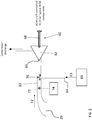
FIG. 2 , thecompressor 42 of thecompression device 40 is illustrated in more detail. As previously described, a second medium F2, such as fresh air for example, enters thesystem 20 from asecond inlet 26. Thesecond inlet 26 is arranged in fluid communication with aninlet 60 of thecompressor 42 via a conduit, illustrated at 62. If thesecond inlet 26 of theECS 20, were to become blocked, thereby restricting the flow of the second medium F2 provided to thecompressor 42, a failure of thecompressor 42, i.e. such as a surge for example, may occur, potentially resulting in damage to theECS 20. For example, thesecond inlet 26 may be blocked by foreign objects or debris drawn into the scoop, or alternatively, by the accumulation of ice thereon. - To reduce the likelihood of the occurrence of a compressor surge condition, the
ECS 20 may additionally include anotherinlet 64 for providing a medium from asource 66 to theinlet 60 of thecompressor 42. Accordingly, thesecond inlet 26 may be considered a primary inlet for supplying a medium thecompressor 42 and theinlet 64 may be considered a secondary inlet for supplying a medium to thecompressor 42. In the illustrated, non-limiting embodiment, the secondary oradditional inlet 64 is connected to theconduit 62 at a position downstream from theprimary inlet 26, and upstream from theinlet 60 of thecompressor 42. However, embodiments where thesecondary inlet 64 is directly connected to theinlet 60 of thecompressor 42 are also within the scope of the disclosure. In embodiments where thesecondary inlet 64 is directly coupled to thecompressor 42, thecompressor 42 may include a plurality of inlet openings, i.e. a first inlet opening (not shown) for receiving the second medium F2 from theprimary inlet 26, and a second inlet opening (not shown) for receiving a medium from thesecondary inlet 64. - In an embodiment, the
secondary inlet 64 is configured to provide additional fresh air (i.e. ambient pressure, outside air) to thecompressor 42. In such embodiments, thesecondary inlet 64 may include one or more scooping mechanisms, such as an impact scoop or a flush scoop for example. In such embodiments, a configuration of one or more scooping mechanisms at thesecondary inlet 64 may be substantially identical to, or may have a configuration than the one or more scooping mechanisms of theprimary inlet 26. Alternatively, thesecondary inlet 64 may be configured to draw air form the interior of the aircraft bay within which the compressor is mounted. - In other embodiments, the
source 66 configured to supply an additional flow of medium to thecompressor 42 via thesecondary inlet 64 may be another component within theECS 20. For example, in an embodiment,secondary inlet 64 may be configured to draw ram air from theram air circuit 30. In an embodiment, thesecondary inlet 64 is configured to draw ram air from within theshell 32 at a position located upstream from the primary andsecondary heat exchangers ram air circuit 30. In another embodiment, a portion of the air supplied to thepower turbine 46 of thecompression device 40 may be used as thesource 66 for delivering additional air to thecompressor 42. For example, as best shown inFIG. 3 , a portion of the third medium F3 either provided to or output from thepower turbine 46 may be rerouted to thesecondary inlet 64 via a conduit, illustrated at 68. - With reference again to
FIG. 2 , the medium from thesecondary inlet 64 may be provided to thecompressor 42 in addition to, or in place of, the medium from theprimary inlet 26. As shown, avalve 70 may be positioned at the interface between thesecondary inlet 64 and theconduit 62 extending from theprimary inlet 26 to thecompressor 42. In an embodiment, thevalve 70 may be a check valve. Accordingly, when the pressure of the second medium F2 provided via theprimary inlet 26 exceeds a pressure threshold of thevalve 70, thevalve 70 is configured to allow a flow of second medium F2 from theprimary inlet 26, but not a flow of medium from thesecondary inlet 64, to thecompressor 42. Once theprimary inlet 26 becomes at least partially blocked, the pressure of the flow of second medium F2 is reduced. If the pressure of the flow of second medium F2 is less than the pressure threshold of thevalve 70, thevalve 70 will transition to allow the medium from thesecondary inlet 64 to flow to thecompressor 42. In the embodiment thatvalve 70 is absent from the system, flow to thecompressor 42 inlet will be supplied by the higher pressure source betweenprimary inlet 26, less the pressure drop from the partial blockage, andsecondary inlet 64. - Alternatively, the
valve 70 may be a control operated valve, movable between a plurality of positions. For example, in a first position, only theprimary inlet 26 is arranged in fluid communication with thecompressor 42, in a second position, only thesecondary inlet 64 is in fluid communication with thecompressor 42, and in a third position, both the primary and thesecondary inlets compressor 42. In an embodiment, asensor 72 is operable to monitor one or more parameters of the flow provided via theprimary inlet 26. Thesensor 72 may be operable to measure a flow rate or pressure for example. Using the sensor data, acontroller 74 operably coupled to thesensor 72 and thevalve 70, can determine whether the flow from theprimary inlet 26 is sufficient to meet the demand of thecompressor 42, and can adjust the position of thevalve 70 accordingly to avoid a surge condition. - An
ECS 20 having both a primary andsecondary inlet compressor 42, as illustrated and described herein has an increased reliability compared to existing systems. By allowing thecompressor 42 to pull air from another source when theprimary inlet 26 is blocked, the likelihood of a compressor surge is reduced or eliminated. - The term "about" is intended to include the degree of error associated with measurement of the particular quantity based upon the equipment available at the time of filing the application.
- The terminology used herein is for the purpose of describing particular embodiments only and is not intended to be limiting of the present disclosure. As used herein, the singular forms "a", "an" and "the" are intended to include the plural forms as well, unless the context clearly indicates otherwise. It will be further understood that the terms "comprises" and/or "comprising," when used in this specification, specify the presence of stated features, integers, steps, operations, elements, and/or components, but do not preclude the presence or addition of one or more other features, integers, steps, operations, element components, and/or groups thereof.
- While the present disclosure has been described with reference to an exemplary embodiment or embodiments, it will be understood by those skilled in the art that various changes may be made and equivalents may be substituted for elements thereof without departing from the scope of the invention as defined by the claims. In addition, many modifications may be made to adapt a particular situation or material to the teachings of the present disclosure without departing from the scope of the invention. Therefore, it is intended that the present disclosure not be limited to the particular embodiment disclosed as the best mode contemplated for carrying out this present disclosure, but that the present disclosure will include all embodiments falling within the scope of the claims.
Claims (15)
- An environmental control system of an aircraft comprising:a compression device (40) including a compressor (42) having a compressor inlet and a compressor outlet;a primary inlet (26) for supplying a first medium to the compressor inlet; anda secondary inlet (64) for supplying a second medium to the compressor inlet.
- The environmental control system of claim 1, wherein the first medium and the second medium are drawn from a same source, and optionally wherein the first medium and the second medium includes fresh, outside air.
- The environmental control system of claim 1, wherein the first medium and the second medium are drawn from separate sources, and optionally wherein the environmental control system further comprises a ram air circuit (30) and the second medium is ram air drawn from the ram air circuit.
- The environmental control system of claim 3, wherein the compression device further comprises a turbine (44) coupled to the compressor by a shaft, wherein the compressor receives energy derived from a cabin discharge air medium expanded across the turbine.
- The environmental control system of claim 4, wherein the second medium includes cabin discharge air drawn from upstream of the turbine, or wherein the second medium includes cabin discharge air output from the turbine.
- The environmental control system of claim 3, wherein the second medium is drawn from a compartment of the aircraft within which the compressor is mounted.
- The environmental control system of any preceding claim, wherein the primary inlet is fluidly coupled to the compressor inlet by a conduit (62), and the secondary inlet is fluidly coupled to the conduit.
- The environmental control system of claim 7, further comprising a valve (70) mounted within the conduit to control a supply of at least one of the first medium and second medium to the compressor inlet.
- The environmental control system of claim 8, wherein the valve is a check valve operable to allow a flow of the second medium to the compressor inlet when a pressure of a flow of the first medium is below a threshold.
- The environmental control system of claim 8 or 9, further comprising a controller (74) operable to move the valve between a plurality of positions to control the supply of at least one of the first medium and second medium to the compressor inlet.
- The environmental control system of claim 10, further comprising a sensor (72) for measuring a parameter of a flow of the first medium, wherein the controller is coupled to the sensor and is configured to adjust a position of the valve in response to the measured parameter.
- The environmental control system of claim 11, wherein the measured parameter is flow rate, or wherein the measured parameter is pressure.
- A method of operating a compression device comprising:expanding a medium across a turbine to operate a compressor coupled to the turbine;providing a first medium from a primary inlet to an inlet of the compressor; andproviding a second medium from a secondary inlet to the inlet of the compressor if a flow of the first medium is below a threshold.
- The method of claim 13, wherein providing the second medium from the secondary inlet to the inlet of the compressor further comprises operating a valve to fluidly couple the secondary inlet to the inlet of the compressor and optionally wherein providing the second medium from the secondary inlet to the inlet of the compressor further comprises operating a valve to fluidly disconnect the primary inlet from the inlet of the compressor
- The method of claim 14, further comprising sensing a parameter associated with the first medium, wherein providing the second medium from the secondary inlet to the inlet of the compressor occurs in response to sensing the parameter associated with the first medium.
Applications Claiming Priority (1)
| Application Number | Priority Date | Filing Date | Title |
|---|---|---|---|
| US16/218,156 US11524789B2 (en) | 2018-12-12 | 2018-12-12 | Alternate fresh air compressor intake for environmental control system |
Publications (2)
| Publication Number | Publication Date |
|---|---|
| EP3666656A1 true EP3666656A1 (en) | 2020-06-17 |
| EP3666656B1 EP3666656B1 (en) | 2021-11-10 |
Family
ID=68886750
Family Applications (1)
| Application Number | Title | Priority Date | Filing Date |
|---|---|---|---|
| EP19215126.4A Active EP3666656B1 (en) | 2018-12-12 | 2019-12-11 | Alternate fresh air compressor intake for environmental control system |
Country Status (2)
| Country | Link |
|---|---|
| US (1) | US11524789B2 (en) |
| EP (1) | EP3666656B1 (en) |
Families Citing this family (4)
| Publication number | Priority date | Publication date | Assignee | Title |
|---|---|---|---|---|
| US11506121B2 (en) * | 2016-05-26 | 2022-11-22 | Hamilton Sundstrand Corporation | Multiple nozzle configurations for a turbine of an environmental control system |
| EP4019403A1 (en) | 2016-05-26 | 2022-06-29 | Hamilton Sundstrand Corporation | Mixing ram and bleed air in a dual entry turbine system |
| EP3249196B1 (en) | 2016-05-26 | 2020-12-02 | Hamilton Sundstrand Corporation | An energy flow of an advanced environmental control system |
| US11077949B2 (en) * | 2018-10-05 | 2021-08-03 | The Boeing Company | Dual turbine thermal management system (TMS) |
Citations (6)
| Publication number | Priority date | Publication date | Assignee | Title |
|---|---|---|---|---|
| EP2591999A2 (en) * | 2011-11-11 | 2013-05-15 | Hamilton Sundstrand Corporation | Turbo air compressor |
| FR2991725A1 (en) * | 2012-06-11 | 2013-12-13 | Valeo Sys Controle Moteur Sas | ASSEMBLY COMPRISING A THERMAL MOTOR AND AN ELECTRIC COMPRESSOR |
| EP2939927A1 (en) * | 2014-05-02 | 2015-11-04 | Hamilton Sundstrand Corporation | Aircraft environmental conditioning system and method |
| EP3187417A1 (en) * | 2015-12-30 | 2017-07-05 | Airbus Operations S.L. | Air conditioning system |
| EP3249196A1 (en) * | 2016-05-26 | 2017-11-29 | Hamilton Sundstrand Corporation | An energy flow of an advanced environmental control system |
| EP3354573A1 (en) * | 2017-01-27 | 2018-08-01 | Hamilton Sundstrand Corporation | Environmental control system in an integrated pack arrangement with one bleed/outflow heat exchanger |
Family Cites Families (14)
| Publication number | Priority date | Publication date | Assignee | Title |
|---|---|---|---|---|
| US5461882A (en) | 1994-07-22 | 1995-10-31 | United Technologies Corporation | Regenerative condensing cycle |
| DE102008026117A1 (en) | 2008-05-30 | 2009-12-10 | Airbus Deutschland Gmbh | Fresh air intake for an aircraft |
| US9254920B2 (en) | 2012-05-30 | 2016-02-09 | General Electric Company | Aircraft energy management system including engine fan discharge air boosted environmental control system |
| US9457908B2 (en) * | 2012-09-20 | 2016-10-04 | Hamilton Sundstrand Corporation | Self-cooled motor driven compressor |
| US9669936B1 (en) | 2012-10-24 | 2017-06-06 | The Boeing Company | Aircraft air conditioning systems and methods |
| US20150065023A1 (en) * | 2013-09-03 | 2015-03-05 | Hamilton Sundstrand Corporation | Intercompressor bleed turbo compressor |
| FR3011819B1 (en) | 2013-10-14 | 2017-04-07 | Liebherr-Aerospace Toulouse Sas | AIR TREATMENT SYSTEM, IN PARTICULAR AT LOW TEMPERATURE, FOR AN AIRCRAFT. |
| EP2998223B1 (en) * | 2014-09-19 | 2018-12-05 | Airbus Operations GmbH | Aircraft air conditioning system and method of operating an aircraft air conditioning system |
| US11466904B2 (en) * | 2014-11-25 | 2022-10-11 | Hamilton Sundstrand Corporation | Environmental control system utilizing cabin air to drive a power turbine of an air cycle machine and utilizing multiple mix points for recirculation air in accordance with pressure mode |
| US10850853B2 (en) * | 2016-04-22 | 2020-12-01 | Hamilton Sunstrand Corporation | Environmental control system utilizing bleed pressure assist |
| EP3248876B1 (en) | 2016-05-26 | 2023-04-26 | Hamilton Sundstrand Corporation | Mixing bleed and ram air at a turbine inlet of a compressing device |
| US20180057170A1 (en) * | 2016-08-23 | 2018-03-01 | Ge Aviation Systems, Llc | Enhanced method and aircraft for pre-cooling an environmental control system using a two wheel turbo-machine with supplemental heat exchanger |
| US10384785B2 (en) | 2017-02-17 | 2019-08-20 | Hamilton Sundstrand Corporation | Two mode system that provides bleed and outside air or just outside air |
| US10843804B2 (en) * | 2017-08-01 | 2020-11-24 | Honeywell International Inc. | Cabin outflow air energy optimized cabin pressurizing system |
-
2018
- 2018-12-12 US US16/218,156 patent/US11524789B2/en active Active
-
2019
- 2019-12-11 EP EP19215126.4A patent/EP3666656B1/en active Active
Patent Citations (6)
| Publication number | Priority date | Publication date | Assignee | Title |
|---|---|---|---|---|
| EP2591999A2 (en) * | 2011-11-11 | 2013-05-15 | Hamilton Sundstrand Corporation | Turbo air compressor |
| FR2991725A1 (en) * | 2012-06-11 | 2013-12-13 | Valeo Sys Controle Moteur Sas | ASSEMBLY COMPRISING A THERMAL MOTOR AND AN ELECTRIC COMPRESSOR |
| EP2939927A1 (en) * | 2014-05-02 | 2015-11-04 | Hamilton Sundstrand Corporation | Aircraft environmental conditioning system and method |
| EP3187417A1 (en) * | 2015-12-30 | 2017-07-05 | Airbus Operations S.L. | Air conditioning system |
| EP3249196A1 (en) * | 2016-05-26 | 2017-11-29 | Hamilton Sundstrand Corporation | An energy flow of an advanced environmental control system |
| EP3354573A1 (en) * | 2017-01-27 | 2018-08-01 | Hamilton Sundstrand Corporation | Environmental control system in an integrated pack arrangement with one bleed/outflow heat exchanger |
Also Published As
| Publication number | Publication date |
|---|---|
| US11524789B2 (en) | 2022-12-13 |
| US20200189749A1 (en) | 2020-06-18 |
| EP3666656B1 (en) | 2021-11-10 |
Similar Documents
| Publication | Publication Date | Title |
|---|---|---|
| US11192655B2 (en) | Regenerative system ECOECS | |
| EP3489142B1 (en) | Aircraft environmental control system with series bleed air turbines | |
| EP3587269B1 (en) | Aircraft environmental control system | |
| EP3666656B1 (en) | Alternate fresh air compressor intake for environmental control system | |
| EP3514065B1 (en) | Aircraft environmental control system | |
| EP3945031B1 (en) | Aircraft environmental control system | |
| US11851190B2 (en) | Aircraft environmental control system | |
| EP3760542A1 (en) | Environmental control system of an aircraft | |
| EP3945029B1 (en) | Aircraft environmental control system | |
| US11994088B2 (en) | Ambient air environmental control system | |
| EP4331991A1 (en) | Environmental control system with low inlet pressure | |
| EP4159988A1 (en) | Ambient air environmental control system | |
| EP4273044A1 (en) | 100% ambient air environmental control system | |
| EP4005925A1 (en) | Ambient air architecture with single air cycle machine and high pressure water separator |
Legal Events
| Date | Code | Title | Description |
|---|---|---|---|
| PUAI | Public reference made under article 153(3) epc to a published international application that has entered the european phase |
Free format text: ORIGINAL CODE: 0009012 |
|
| STAA | Information on the status of an ep patent application or granted ep patent |
Free format text: STATUS: THE APPLICATION HAS BEEN PUBLISHED |
|
| AK | Designated contracting states |
Kind code of ref document: A1 Designated state(s): AL AT BE BG CH CY CZ DE DK EE ES FI FR GB GR HR HU IE IS IT LI LT LU LV MC MK MT NL NO PL PT RO RS SE SI SK SM TR |
|
| AX | Request for extension of the european patent |
Extension state: BA ME |
|
| STAA | Information on the status of an ep patent application or granted ep patent |
Free format text: STATUS: REQUEST FOR EXAMINATION WAS MADE |
|
| 17P | Request for examination filed |
Effective date: 20201217 |
|
| RBV | Designated contracting states (corrected) |
Designated state(s): AL AT BE BG CH CY CZ DE DK EE ES FI FR GB GR HR HU IE IS IT LI LT LU LV MC MK MT NL NO PL PT RO RS SE SI SK SM TR |
|
| GRAP | Despatch of communication of intention to grant a patent |
Free format text: ORIGINAL CODE: EPIDOSNIGR1 |
|
| STAA | Information on the status of an ep patent application or granted ep patent |
Free format text: STATUS: GRANT OF PATENT IS INTENDED |
|
| RIC1 | Information provided on ipc code assigned before grant |
Ipc: B64D 13/06 20060101AFI20210430BHEP |
|
| INTG | Intention to grant announced |
Effective date: 20210601 |
|
| GRAS | Grant fee paid |
Free format text: ORIGINAL CODE: EPIDOSNIGR3 |
|
| GRAA | (expected) grant |
Free format text: ORIGINAL CODE: 0009210 |
|
| STAA | Information on the status of an ep patent application or granted ep patent |
Free format text: STATUS: THE PATENT HAS BEEN GRANTED |
|
| AK | Designated contracting states |
Kind code of ref document: B1 Designated state(s): AL AT BE BG CH CY CZ DE DK EE ES FI FR GB GR HR HU IE IS IT LI LT LU LV MC MK MT NL NO PL PT RO RS SE SI SK SM TR |
|
| REG | Reference to a national code |
Ref country code: GB Ref legal event code: FG4D |
|
| REG | Reference to a national code |
Ref country code: AT Ref legal event code: REF Ref document number: 1445880 Country of ref document: AT Kind code of ref document: T Effective date: 20211115 Ref country code: CH Ref legal event code: EP |
|
| REG | Reference to a national code |
Ref country code: DE Ref legal event code: R096 Ref document number: 602019009156 Country of ref document: DE |
|
| REG | Reference to a national code |
Ref country code: IE Ref legal event code: FG4D |
|
| REG | Reference to a national code |
Ref country code: LT Ref legal event code: MG9D |
|
| REG | Reference to a national code |
Ref country code: NL Ref legal event code: MP Effective date: 20211110 |
|
| REG | Reference to a national code |
Ref country code: AT Ref legal event code: MK05 Ref document number: 1445880 Country of ref document: AT Kind code of ref document: T Effective date: 20211110 |
|
| PG25 | Lapsed in a contracting state [announced via postgrant information from national office to epo] |
Ref country code: RS Free format text: LAPSE BECAUSE OF FAILURE TO SUBMIT A TRANSLATION OF THE DESCRIPTION OR TO PAY THE FEE WITHIN THE PRESCRIBED TIME-LIMIT Effective date: 20211110 Ref country code: LT Free format text: LAPSE BECAUSE OF FAILURE TO SUBMIT A TRANSLATION OF THE DESCRIPTION OR TO PAY THE FEE WITHIN THE PRESCRIBED TIME-LIMIT Effective date: 20211110 Ref country code: FI Free format text: LAPSE BECAUSE OF FAILURE TO SUBMIT A TRANSLATION OF THE DESCRIPTION OR TO PAY THE FEE WITHIN THE PRESCRIBED TIME-LIMIT Effective date: 20211110 Ref country code: BG Free format text: LAPSE BECAUSE OF FAILURE TO SUBMIT A TRANSLATION OF THE DESCRIPTION OR TO PAY THE FEE WITHIN THE PRESCRIBED TIME-LIMIT Effective date: 20220210 Ref country code: AT Free format text: LAPSE BECAUSE OF FAILURE TO SUBMIT A TRANSLATION OF THE DESCRIPTION OR TO PAY THE FEE WITHIN THE PRESCRIBED TIME-LIMIT Effective date: 20211110 |
|
| PG25 | Lapsed in a contracting state [announced via postgrant information from national office to epo] |
Ref country code: IS Free format text: LAPSE BECAUSE OF FAILURE TO SUBMIT A TRANSLATION OF THE DESCRIPTION OR TO PAY THE FEE WITHIN THE PRESCRIBED TIME-LIMIT Effective date: 20220310 Ref country code: SE Free format text: LAPSE BECAUSE OF FAILURE TO SUBMIT A TRANSLATION OF THE DESCRIPTION OR TO PAY THE FEE WITHIN THE PRESCRIBED TIME-LIMIT Effective date: 20211110 Ref country code: PT Free format text: LAPSE BECAUSE OF FAILURE TO SUBMIT A TRANSLATION OF THE DESCRIPTION OR TO PAY THE FEE WITHIN THE PRESCRIBED TIME-LIMIT Effective date: 20220310 Ref country code: PL Free format text: LAPSE BECAUSE OF FAILURE TO SUBMIT A TRANSLATION OF THE DESCRIPTION OR TO PAY THE FEE WITHIN THE PRESCRIBED TIME-LIMIT Effective date: 20211110 Ref country code: NO Free format text: LAPSE BECAUSE OF FAILURE TO SUBMIT A TRANSLATION OF THE DESCRIPTION OR TO PAY THE FEE WITHIN THE PRESCRIBED TIME-LIMIT Effective date: 20220210 Ref country code: NL Free format text: LAPSE BECAUSE OF FAILURE TO SUBMIT A TRANSLATION OF THE DESCRIPTION OR TO PAY THE FEE WITHIN THE PRESCRIBED TIME-LIMIT Effective date: 20211110 Ref country code: LV Free format text: LAPSE BECAUSE OF FAILURE TO SUBMIT A TRANSLATION OF THE DESCRIPTION OR TO PAY THE FEE WITHIN THE PRESCRIBED TIME-LIMIT Effective date: 20211110 Ref country code: HR Free format text: LAPSE BECAUSE OF FAILURE TO SUBMIT A TRANSLATION OF THE DESCRIPTION OR TO PAY THE FEE WITHIN THE PRESCRIBED TIME-LIMIT Effective date: 20211110 Ref country code: GR Free format text: LAPSE BECAUSE OF FAILURE TO SUBMIT A TRANSLATION OF THE DESCRIPTION OR TO PAY THE FEE WITHIN THE PRESCRIBED TIME-LIMIT Effective date: 20220211 Ref country code: ES Free format text: LAPSE BECAUSE OF FAILURE TO SUBMIT A TRANSLATION OF THE DESCRIPTION OR TO PAY THE FEE WITHIN THE PRESCRIBED TIME-LIMIT Effective date: 20211110 |
|
| PG25 | Lapsed in a contracting state [announced via postgrant information from national office to epo] |
Ref country code: SM Free format text: LAPSE BECAUSE OF FAILURE TO SUBMIT A TRANSLATION OF THE DESCRIPTION OR TO PAY THE FEE WITHIN THE PRESCRIBED TIME-LIMIT Effective date: 20211110 Ref country code: SK Free format text: LAPSE BECAUSE OF FAILURE TO SUBMIT A TRANSLATION OF THE DESCRIPTION OR TO PAY THE FEE WITHIN THE PRESCRIBED TIME-LIMIT Effective date: 20211110 Ref country code: RO Free format text: LAPSE BECAUSE OF FAILURE TO SUBMIT A TRANSLATION OF THE DESCRIPTION OR TO PAY THE FEE WITHIN THE PRESCRIBED TIME-LIMIT Effective date: 20211110 Ref country code: EE Free format text: LAPSE BECAUSE OF FAILURE TO SUBMIT A TRANSLATION OF THE DESCRIPTION OR TO PAY THE FEE WITHIN THE PRESCRIBED TIME-LIMIT Effective date: 20211110 Ref country code: DK Free format text: LAPSE BECAUSE OF FAILURE TO SUBMIT A TRANSLATION OF THE DESCRIPTION OR TO PAY THE FEE WITHIN THE PRESCRIBED TIME-LIMIT Effective date: 20211110 Ref country code: CZ Free format text: LAPSE BECAUSE OF FAILURE TO SUBMIT A TRANSLATION OF THE DESCRIPTION OR TO PAY THE FEE WITHIN THE PRESCRIBED TIME-LIMIT Effective date: 20211110 |
|
| REG | Reference to a national code |
Ref country code: DE Ref legal event code: R097 Ref document number: 602019009156 Country of ref document: DE |
|
| PG25 | Lapsed in a contracting state [announced via postgrant information from national office to epo] |
Ref country code: MC Free format text: LAPSE BECAUSE OF FAILURE TO SUBMIT A TRANSLATION OF THE DESCRIPTION OR TO PAY THE FEE WITHIN THE PRESCRIBED TIME-LIMIT Effective date: 20211110 |
|
| PLBE | No opposition filed within time limit |
Free format text: ORIGINAL CODE: 0009261 |
|
| STAA | Information on the status of an ep patent application or granted ep patent |
Free format text: STATUS: NO OPPOSITION FILED WITHIN TIME LIMIT |
|
| REG | Reference to a national code |
Ref country code: BE Ref legal event code: MM Effective date: 20211231 |
|
| 26N | No opposition filed |
Effective date: 20220811 |
|
| PG25 | Lapsed in a contracting state [announced via postgrant information from national office to epo] |
Ref country code: LU Free format text: LAPSE BECAUSE OF NON-PAYMENT OF DUE FEES Effective date: 20211211 Ref country code: IE Free format text: LAPSE BECAUSE OF NON-PAYMENT OF DUE FEES Effective date: 20211211 Ref country code: AL Free format text: LAPSE BECAUSE OF FAILURE TO SUBMIT A TRANSLATION OF THE DESCRIPTION OR TO PAY THE FEE WITHIN THE PRESCRIBED TIME-LIMIT Effective date: 20211110 |
|
| PG25 | Lapsed in a contracting state [announced via postgrant information from national office to epo] |
Ref country code: SI Free format text: LAPSE BECAUSE OF FAILURE TO SUBMIT A TRANSLATION OF THE DESCRIPTION OR TO PAY THE FEE WITHIN THE PRESCRIBED TIME-LIMIT Effective date: 20211110 Ref country code: BE Free format text: LAPSE BECAUSE OF NON-PAYMENT OF DUE FEES Effective date: 20211231 |
|
| PG25 | Lapsed in a contracting state [announced via postgrant information from national office to epo] |
Ref country code: IT Free format text: LAPSE BECAUSE OF FAILURE TO SUBMIT A TRANSLATION OF THE DESCRIPTION OR TO PAY THE FEE WITHIN THE PRESCRIBED TIME-LIMIT Effective date: 20211110 |
|
| PG25 | Lapsed in a contracting state [announced via postgrant information from national office to epo] |
Ref country code: CY Free format text: LAPSE BECAUSE OF FAILURE TO SUBMIT A TRANSLATION OF THE DESCRIPTION OR TO PAY THE FEE WITHIN THE PRESCRIBED TIME-LIMIT Effective date: 20211110 |
|
| P01 | Opt-out of the competence of the unified patent court (upc) registered |
Effective date: 20230603 |
|
| PG25 | Lapsed in a contracting state [announced via postgrant information from national office to epo] |
Ref country code: HU Free format text: LAPSE BECAUSE OF FAILURE TO SUBMIT A TRANSLATION OF THE DESCRIPTION OR TO PAY THE FEE WITHIN THE PRESCRIBED TIME-LIMIT; INVALID AB INITIO Effective date: 20191211 |
|
| REG | Reference to a national code |
Ref country code: CH Ref legal event code: PL |
|
| PG25 | Lapsed in a contracting state [announced via postgrant information from national office to epo] |
Ref country code: LI Free format text: LAPSE BECAUSE OF NON-PAYMENT OF DUE FEES Effective date: 20221231 Ref country code: CH Free format text: LAPSE BECAUSE OF NON-PAYMENT OF DUE FEES Effective date: 20221231 |
|
| PGFP | Annual fee paid to national office [announced via postgrant information from national office to epo] |
Ref country code: GB Payment date: 20231121 Year of fee payment: 5 |
|
| PGFP | Annual fee paid to national office [announced via postgrant information from national office to epo] |
Ref country code: FR Payment date: 20231122 Year of fee payment: 5 Ref country code: DE Payment date: 20231121 Year of fee payment: 5 |
|
| PG25 | Lapsed in a contracting state [announced via postgrant information from national office to epo] |
Ref country code: MK Free format text: LAPSE BECAUSE OF FAILURE TO SUBMIT A TRANSLATION OF THE DESCRIPTION OR TO PAY THE FEE WITHIN THE PRESCRIBED TIME-LIMIT Effective date: 20211110 |