EP3666613B1 - Vehicle and method for controlling same - Google Patents
Vehicle and method for controlling same Download PDFInfo
- Publication number
- EP3666613B1 EP3666613B1 EP18887087.7A EP18887087A EP3666613B1 EP 3666613 B1 EP3666613 B1 EP 3666613B1 EP 18887087 A EP18887087 A EP 18887087A EP 3666613 B1 EP3666613 B1 EP 3666613B1
- Authority
- EP
- European Patent Office
- Prior art keywords
- image
- vehicle
- surrounding environment
- traffic sign
- sign information
- Prior art date
- Legal status (The legal status is an assumption and is not a legal conclusion. Google has not performed a legal analysis and makes no representation as to the accuracy of the status listed.)
- Active
Links
Images



Classifications
-
- B—PERFORMING OPERATIONS; TRANSPORTING
- B60—VEHICLES IN GENERAL
- B60W—CONJOINT CONTROL OF VEHICLE SUB-UNITS OF DIFFERENT TYPE OR DIFFERENT FUNCTION; CONTROL SYSTEMS SPECIALLY ADAPTED FOR HYBRID VEHICLES; ROAD VEHICLE DRIVE CONTROL SYSTEMS FOR PURPOSES NOT RELATED TO THE CONTROL OF A PARTICULAR SUB-UNIT
- B60W60/00—Drive control systems specially adapted for autonomous road vehicles
- B60W60/001—Planning or execution of driving tasks
- B60W60/0025—Planning or execution of driving tasks specially adapted for specific operations
-
- B—PERFORMING OPERATIONS; TRANSPORTING
- B60—VEHICLES IN GENERAL
- B60W—CONJOINT CONTROL OF VEHICLE SUB-UNITS OF DIFFERENT TYPE OR DIFFERENT FUNCTION; CONTROL SYSTEMS SPECIALLY ADAPTED FOR HYBRID VEHICLES; ROAD VEHICLE DRIVE CONTROL SYSTEMS FOR PURPOSES NOT RELATED TO THE CONTROL OF A PARTICULAR SUB-UNIT
- B60W40/00—Estimation or calculation of non-directly measurable driving parameters for road vehicle drive control systems not related to the control of a particular sub unit, e.g. by using mathematical models
- B60W40/02—Estimation or calculation of non-directly measurable driving parameters for road vehicle drive control systems not related to the control of a particular sub unit, e.g. by using mathematical models related to ambient conditions
-
- B—PERFORMING OPERATIONS; TRANSPORTING
- B60—VEHICLES IN GENERAL
- B60K—ARRANGEMENT OR MOUNTING OF PROPULSION UNITS OR OF TRANSMISSIONS IN VEHICLES; ARRANGEMENT OR MOUNTING OF PLURAL DIVERSE PRIME-MOVERS IN VEHICLES; AUXILIARY DRIVES FOR VEHICLES; INSTRUMENTATION OR DASHBOARDS FOR VEHICLES; ARRANGEMENTS IN CONNECTION WITH COOLING, AIR INTAKE, GAS EXHAUST OR FUEL SUPPLY OF PROPULSION UNITS IN VEHICLES
- B60K35/00—Instruments specially adapted for vehicles; Arrangement of instruments in or on vehicles
- B60K35/10—Input arrangements, i.e. from user to vehicle, associated with vehicle functions or specially adapted therefor
-
- B—PERFORMING OPERATIONS; TRANSPORTING
- B60—VEHICLES IN GENERAL
- B60K—ARRANGEMENT OR MOUNTING OF PROPULSION UNITS OR OF TRANSMISSIONS IN VEHICLES; ARRANGEMENT OR MOUNTING OF PLURAL DIVERSE PRIME-MOVERS IN VEHICLES; AUXILIARY DRIVES FOR VEHICLES; INSTRUMENTATION OR DASHBOARDS FOR VEHICLES; ARRANGEMENTS IN CONNECTION WITH COOLING, AIR INTAKE, GAS EXHAUST OR FUEL SUPPLY OF PROPULSION UNITS IN VEHICLES
- B60K35/00—Instruments specially adapted for vehicles; Arrangement of instruments in or on vehicles
- B60K35/20—Output arrangements, i.e. from vehicle to user, associated with vehicle functions or specially adapted therefor
- B60K35/21—Output arrangements, i.e. from vehicle to user, associated with vehicle functions or specially adapted therefor using visual output, e.g. blinking lights or matrix displays
- B60K35/23—Head-up displays [HUD]
-
- B—PERFORMING OPERATIONS; TRANSPORTING
- B60—VEHICLES IN GENERAL
- B60K—ARRANGEMENT OR MOUNTING OF PROPULSION UNITS OR OF TRANSMISSIONS IN VEHICLES; ARRANGEMENT OR MOUNTING OF PLURAL DIVERSE PRIME-MOVERS IN VEHICLES; AUXILIARY DRIVES FOR VEHICLES; INSTRUMENTATION OR DASHBOARDS FOR VEHICLES; ARRANGEMENTS IN CONNECTION WITH COOLING, AIR INTAKE, GAS EXHAUST OR FUEL SUPPLY OF PROPULSION UNITS IN VEHICLES
- B60K35/00—Instruments specially adapted for vehicles; Arrangement of instruments in or on vehicles
- B60K35/20—Output arrangements, i.e. from vehicle to user, associated with vehicle functions or specially adapted therefor
- B60K35/28—Output arrangements, i.e. from vehicle to user, associated with vehicle functions or specially adapted therefor characterised by the type of the output information, e.g. video entertainment or vehicle dynamics information; characterised by the purpose of the output information, e.g. for attracting the attention of the driver
-
- B—PERFORMING OPERATIONS; TRANSPORTING
- B60—VEHICLES IN GENERAL
- B60R—VEHICLES, VEHICLE FITTINGS, OR VEHICLE PARTS, NOT OTHERWISE PROVIDED FOR
- B60R1/00—Optical viewing arrangements; Real-time viewing arrangements for drivers or passengers using optical image capturing systems, e.g. cameras or video systems specially adapted for use in or on vehicles
- B60R1/20—Real-time viewing arrangements for drivers or passengers using optical image capturing systems, e.g. cameras or video systems specially adapted for use in or on vehicles
- B60R1/22—Real-time viewing arrangements for drivers or passengers using optical image capturing systems, e.g. cameras or video systems specially adapted for use in or on vehicles for viewing an area outside the vehicle, e.g. the exterior of the vehicle
- B60R1/23—Real-time viewing arrangements for drivers or passengers using optical image capturing systems, e.g. cameras or video systems specially adapted for use in or on vehicles for viewing an area outside the vehicle, e.g. the exterior of the vehicle with a predetermined field of view
- B60R1/24—Real-time viewing arrangements for drivers or passengers using optical image capturing systems, e.g. cameras or video systems specially adapted for use in or on vehicles for viewing an area outside the vehicle, e.g. the exterior of the vehicle with a predetermined field of view in front of the vehicle
-
- B—PERFORMING OPERATIONS; TRANSPORTING
- B60—VEHICLES IN GENERAL
- B60R—VEHICLES, VEHICLE FITTINGS, OR VEHICLE PARTS, NOT OTHERWISE PROVIDED FOR
- B60R1/00—Optical viewing arrangements; Real-time viewing arrangements for drivers or passengers using optical image capturing systems, e.g. cameras or video systems specially adapted for use in or on vehicles
- B60R1/20—Real-time viewing arrangements for drivers or passengers using optical image capturing systems, e.g. cameras or video systems specially adapted for use in or on vehicles
- B60R1/22—Real-time viewing arrangements for drivers or passengers using optical image capturing systems, e.g. cameras or video systems specially adapted for use in or on vehicles for viewing an area outside the vehicle, e.g. the exterior of the vehicle
- B60R1/23—Real-time viewing arrangements for drivers or passengers using optical image capturing systems, e.g. cameras or video systems specially adapted for use in or on vehicles for viewing an area outside the vehicle, e.g. the exterior of the vehicle with a predetermined field of view
- B60R1/27—Real-time viewing arrangements for drivers or passengers using optical image capturing systems, e.g. cameras or video systems specially adapted for use in or on vehicles for viewing an area outside the vehicle, e.g. the exterior of the vehicle with a predetermined field of view providing all-round vision, e.g. using omnidirectional cameras
-
- B—PERFORMING OPERATIONS; TRANSPORTING
- B60—VEHICLES IN GENERAL
- B60W—CONJOINT CONTROL OF VEHICLE SUB-UNITS OF DIFFERENT TYPE OR DIFFERENT FUNCTION; CONTROL SYSTEMS SPECIALLY ADAPTED FOR HYBRID VEHICLES; ROAD VEHICLE DRIVE CONTROL SYSTEMS FOR PURPOSES NOT RELATED TO THE CONTROL OF A PARTICULAR SUB-UNIT
- B60W30/00—Purposes of road vehicle drive control systems not related to the control of a particular sub-unit, e.g. of systems using conjoint control of vehicle sub-units
- B60W30/14—Adaptive cruise control
-
- B—PERFORMING OPERATIONS; TRANSPORTING
- B60—VEHICLES IN GENERAL
- B60W—CONJOINT CONTROL OF VEHICLE SUB-UNITS OF DIFFERENT TYPE OR DIFFERENT FUNCTION; CONTROL SYSTEMS SPECIALLY ADAPTED FOR HYBRID VEHICLES; ROAD VEHICLE DRIVE CONTROL SYSTEMS FOR PURPOSES NOT RELATED TO THE CONTROL OF A PARTICULAR SUB-UNIT
- B60W40/00—Estimation or calculation of non-directly measurable driving parameters for road vehicle drive control systems not related to the control of a particular sub unit, e.g. by using mathematical models
- B60W40/10—Estimation or calculation of non-directly measurable driving parameters for road vehicle drive control systems not related to the control of a particular sub unit, e.g. by using mathematical models related to vehicle motion
-
- B—PERFORMING OPERATIONS; TRANSPORTING
- B60—VEHICLES IN GENERAL
- B60W—CONJOINT CONTROL OF VEHICLE SUB-UNITS OF DIFFERENT TYPE OR DIFFERENT FUNCTION; CONTROL SYSTEMS SPECIALLY ADAPTED FOR HYBRID VEHICLES; ROAD VEHICLE DRIVE CONTROL SYSTEMS FOR PURPOSES NOT RELATED TO THE CONTROL OF A PARTICULAR SUB-UNIT
- B60W50/00—Details of control systems for road vehicle drive control not related to the control of a particular sub-unit, e.g. process diagnostic or vehicle driver interfaces
- B60W50/08—Interaction between the driver and the control system
- B60W50/14—Means for informing the driver, warning the driver or prompting a driver intervention
-
- B—PERFORMING OPERATIONS; TRANSPORTING
- B60—VEHICLES IN GENERAL
- B60W—CONJOINT CONTROL OF VEHICLE SUB-UNITS OF DIFFERENT TYPE OR DIFFERENT FUNCTION; CONTROL SYSTEMS SPECIALLY ADAPTED FOR HYBRID VEHICLES; ROAD VEHICLE DRIVE CONTROL SYSTEMS FOR PURPOSES NOT RELATED TO THE CONTROL OF A PARTICULAR SUB-UNIT
- B60W60/00—Drive control systems specially adapted for autonomous road vehicles
- B60W60/001—Planning or execution of driving tasks
-
- B—PERFORMING OPERATIONS; TRANSPORTING
- B60—VEHICLES IN GENERAL
- B60W—CONJOINT CONTROL OF VEHICLE SUB-UNITS OF DIFFERENT TYPE OR DIFFERENT FUNCTION; CONTROL SYSTEMS SPECIALLY ADAPTED FOR HYBRID VEHICLES; ROAD VEHICLE DRIVE CONTROL SYSTEMS FOR PURPOSES NOT RELATED TO THE CONTROL OF A PARTICULAR SUB-UNIT
- B60W60/00—Drive control systems specially adapted for autonomous road vehicles
- B60W60/001—Planning or execution of driving tasks
- B60W60/0011—Planning or execution of driving tasks involving control alternatives for a single driving scenario, e.g. planning several paths to avoid obstacles
-
- B—PERFORMING OPERATIONS; TRANSPORTING
- B60—VEHICLES IN GENERAL
- B60W—CONJOINT CONTROL OF VEHICLE SUB-UNITS OF DIFFERENT TYPE OR DIFFERENT FUNCTION; CONTROL SYSTEMS SPECIALLY ADAPTED FOR HYBRID VEHICLES; ROAD VEHICLE DRIVE CONTROL SYSTEMS FOR PURPOSES NOT RELATED TO THE CONTROL OF A PARTICULAR SUB-UNIT
- B60W60/00—Drive control systems specially adapted for autonomous road vehicles
- B60W60/001—Planning or execution of driving tasks
- B60W60/0015—Planning or execution of driving tasks specially adapted for safety
- B60W60/0018—Planning or execution of driving tasks specially adapted for safety by employing degraded modes, e.g. reducing speed, in response to suboptimal conditions
- B60W60/00182—Planning or execution of driving tasks specially adapted for safety by employing degraded modes, e.g. reducing speed, in response to suboptimal conditions in response to weather conditions
-
- G—PHYSICS
- G02—OPTICS
- G02B—OPTICAL ELEMENTS, SYSTEMS OR APPARATUS
- G02B27/00—Optical systems or apparatus not provided for by any of the groups G02B1/00 - G02B26/00, G02B30/00
- G02B27/01—Head-up displays
-
- G—PHYSICS
- G02—OPTICS
- G02B—OPTICAL ELEMENTS, SYSTEMS OR APPARATUS
- G02B27/00—Optical systems or apparatus not provided for by any of the groups G02B1/00 - G02B26/00, G02B30/00
- G02B27/01—Head-up displays
- G02B27/0101—Head-up displays characterised by optical features
-
- G—PHYSICS
- G06—COMPUTING OR CALCULATING; COUNTING
- G06F—ELECTRIC DIGITAL DATA PROCESSING
- G06F18/00—Pattern recognition
- G06F18/20—Analysing
- G06F18/23—Clustering techniques
- G06F18/231—Hierarchical techniques, i.e. dividing or merging pattern sets so as to obtain a dendrogram
-
- G—PHYSICS
- G06—COMPUTING OR CALCULATING; COUNTING
- G06F—ELECTRIC DIGITAL DATA PROCESSING
- G06F18/00—Pattern recognition
- G06F18/20—Analysing
- G06F18/24—Classification techniques
- G06F18/241—Classification techniques relating to the classification model, e.g. parametric or non-parametric approaches
- G06F18/2413—Classification techniques relating to the classification model, e.g. parametric or non-parametric approaches based on distances to training or reference patterns
-
- G—PHYSICS
- G06—COMPUTING OR CALCULATING; COUNTING
- G06V—IMAGE OR VIDEO RECOGNITION OR UNDERSTANDING
- G06V20/00—Scenes; Scene-specific elements
- G06V20/50—Context or environment of the image
- G06V20/56—Context or environment of the image exterior to a vehicle by using sensors mounted on the vehicle
-
- G—PHYSICS
- G06—COMPUTING OR CALCULATING; COUNTING
- G06V—IMAGE OR VIDEO RECOGNITION OR UNDERSTANDING
- G06V20/00—Scenes; Scene-specific elements
- G06V20/50—Context or environment of the image
- G06V20/56—Context or environment of the image exterior to a vehicle by using sensors mounted on the vehicle
- G06V20/58—Recognition of moving objects or obstacles, e.g. vehicles or pedestrians; Recognition of traffic objects, e.g. traffic signs, traffic lights or roads
- G06V20/582—Recognition of moving objects or obstacles, e.g. vehicles or pedestrians; Recognition of traffic objects, e.g. traffic signs, traffic lights or roads of traffic signs
-
- B—PERFORMING OPERATIONS; TRANSPORTING
- B60—VEHICLES IN GENERAL
- B60K—ARRANGEMENT OR MOUNTING OF PROPULSION UNITS OR OF TRANSMISSIONS IN VEHICLES; ARRANGEMENT OR MOUNTING OF PLURAL DIVERSE PRIME-MOVERS IN VEHICLES; AUXILIARY DRIVES FOR VEHICLES; INSTRUMENTATION OR DASHBOARDS FOR VEHICLES; ARRANGEMENTS IN CONNECTION WITH COOLING, AIR INTAKE, GAS EXHAUST OR FUEL SUPPLY OF PROPULSION UNITS IN VEHICLES
- B60K2360/00—Indexing scheme associated with groups B60K35/00 or B60K37/00 relating to details of instruments or dashboards
- B60K2360/16—Type of output information
- B60K2360/176—Camera images
-
- B—PERFORMING OPERATIONS; TRANSPORTING
- B60—VEHICLES IN GENERAL
- B60K—ARRANGEMENT OR MOUNTING OF PROPULSION UNITS OR OF TRANSMISSIONS IN VEHICLES; ARRANGEMENT OR MOUNTING OF PLURAL DIVERSE PRIME-MOVERS IN VEHICLES; AUXILIARY DRIVES FOR VEHICLES; INSTRUMENTATION OR DASHBOARDS FOR VEHICLES; ARRANGEMENTS IN CONNECTION WITH COOLING, AIR INTAKE, GAS EXHAUST OR FUEL SUPPLY OF PROPULSION UNITS IN VEHICLES
- B60K2360/00—Indexing scheme associated with groups B60K35/00 or B60K37/00 relating to details of instruments or dashboards
- B60K2360/16—Type of output information
- B60K2360/177—Augmented reality
-
- B—PERFORMING OPERATIONS; TRANSPORTING
- B60—VEHICLES IN GENERAL
- B60R—VEHICLES, VEHICLE FITTINGS, OR VEHICLE PARTS, NOT OTHERWISE PROVIDED FOR
- B60R2300/00—Details of viewing arrangements using cameras and displays, specially adapted for use in a vehicle
- B60R2300/20—Details of viewing arrangements using cameras and displays, specially adapted for use in a vehicle characterised by the type of display used
- B60R2300/205—Details of viewing arrangements using cameras and displays, specially adapted for use in a vehicle characterised by the type of display used using a head-up display
-
- B—PERFORMING OPERATIONS; TRANSPORTING
- B60—VEHICLES IN GENERAL
- B60R—VEHICLES, VEHICLE FITTINGS, OR VEHICLE PARTS, NOT OTHERWISE PROVIDED FOR
- B60R2300/00—Details of viewing arrangements using cameras and displays, specially adapted for use in a vehicle
- B60R2300/30—Details of viewing arrangements using cameras and displays, specially adapted for use in a vehicle characterised by the type of image processing
- B60R2300/307—Details of viewing arrangements using cameras and displays, specially adapted for use in a vehicle characterised by the type of image processing virtually distinguishing relevant parts of a scene from the background of the scene
- B60R2300/308—Details of viewing arrangements using cameras and displays, specially adapted for use in a vehicle characterised by the type of image processing virtually distinguishing relevant parts of a scene from the background of the scene by overlaying the real scene, e.g. through a head-up display on the windscreen
-
- B—PERFORMING OPERATIONS; TRANSPORTING
- B60—VEHICLES IN GENERAL
- B60W—CONJOINT CONTROL OF VEHICLE SUB-UNITS OF DIFFERENT TYPE OR DIFFERENT FUNCTION; CONTROL SYSTEMS SPECIALLY ADAPTED FOR HYBRID VEHICLES; ROAD VEHICLE DRIVE CONTROL SYSTEMS FOR PURPOSES NOT RELATED TO THE CONTROL OF A PARTICULAR SUB-UNIT
- B60W50/00—Details of control systems for road vehicle drive control not related to the control of a particular sub-unit, e.g. process diagnostic or vehicle driver interfaces
- B60W2050/0001—Details of the control system
- B60W2050/0002—Automatic control, details of type of controller or control system architecture
- B60W2050/0004—In digital systems, e.g. discrete-time systems involving sampling
- B60W2050/0005—Processor details or data handling, e.g. memory registers or chip architecture
-
- B—PERFORMING OPERATIONS; TRANSPORTING
- B60—VEHICLES IN GENERAL
- B60W—CONJOINT CONTROL OF VEHICLE SUB-UNITS OF DIFFERENT TYPE OR DIFFERENT FUNCTION; CONTROL SYSTEMS SPECIALLY ADAPTED FOR HYBRID VEHICLES; ROAD VEHICLE DRIVE CONTROL SYSTEMS FOR PURPOSES NOT RELATED TO THE CONTROL OF A PARTICULAR SUB-UNIT
- B60W2420/00—Indexing codes relating to the type of sensors based on the principle of their operation
- B60W2420/40—Photo, light or radio wave sensitive means, e.g. infrared sensors
- B60W2420/403—Image sensing, e.g. optical camera
-
- B—PERFORMING OPERATIONS; TRANSPORTING
- B60—VEHICLES IN GENERAL
- B60W—CONJOINT CONTROL OF VEHICLE SUB-UNITS OF DIFFERENT TYPE OR DIFFERENT FUNCTION; CONTROL SYSTEMS SPECIALLY ADAPTED FOR HYBRID VEHICLES; ROAD VEHICLE DRIVE CONTROL SYSTEMS FOR PURPOSES NOT RELATED TO THE CONTROL OF A PARTICULAR SUB-UNIT
- B60W2552/00—Input parameters relating to infrastructure
- B60W2552/53—Road markings, e.g. lane marker or crosswalk
-
- B—PERFORMING OPERATIONS; TRANSPORTING
- B60—VEHICLES IN GENERAL
- B60W—CONJOINT CONTROL OF VEHICLE SUB-UNITS OF DIFFERENT TYPE OR DIFFERENT FUNCTION; CONTROL SYSTEMS SPECIALLY ADAPTED FOR HYBRID VEHICLES; ROAD VEHICLE DRIVE CONTROL SYSTEMS FOR PURPOSES NOT RELATED TO THE CONTROL OF A PARTICULAR SUB-UNIT
- B60W2555/00—Input parameters relating to exterior conditions, not covered by groups B60W2552/00, B60W2554/00
- B60W2555/20—Ambient conditions, e.g. wind or rain
-
- B—PERFORMING OPERATIONS; TRANSPORTING
- B60—VEHICLES IN GENERAL
- B60W—CONJOINT CONTROL OF VEHICLE SUB-UNITS OF DIFFERENT TYPE OR DIFFERENT FUNCTION; CONTROL SYSTEMS SPECIALLY ADAPTED FOR HYBRID VEHICLES; ROAD VEHICLE DRIVE CONTROL SYSTEMS FOR PURPOSES NOT RELATED TO THE CONTROL OF A PARTICULAR SUB-UNIT
- B60W2555/00—Input parameters relating to exterior conditions, not covered by groups B60W2552/00, B60W2554/00
- B60W2555/60—Traffic rules, e.g. speed limits or right of way
-
- B—PERFORMING OPERATIONS; TRANSPORTING
- B60—VEHICLES IN GENERAL
- B60W—CONJOINT CONTROL OF VEHICLE SUB-UNITS OF DIFFERENT TYPE OR DIFFERENT FUNCTION; CONTROL SYSTEMS SPECIALLY ADAPTED FOR HYBRID VEHICLES; ROAD VEHICLE DRIVE CONTROL SYSTEMS FOR PURPOSES NOT RELATED TO THE CONTROL OF A PARTICULAR SUB-UNIT
- B60W2556/00—Input parameters relating to data
- B60W2556/40—High definition maps
-
- G—PHYSICS
- G02—OPTICS
- G02B—OPTICAL ELEMENTS, SYSTEMS OR APPARATUS
- G02B27/00—Optical systems or apparatus not provided for by any of the groups G02B1/00 - G02B26/00, G02B30/00
- G02B27/01—Head-up displays
- G02B27/0101—Head-up displays characterised by optical features
- G02B2027/0138—Head-up displays characterised by optical features comprising image capture systems, e.g. camera
-
- G—PHYSICS
- G02—OPTICS
- G02B—OPTICAL ELEMENTS, SYSTEMS OR APPARATUS
- G02B27/00—Optical systems or apparatus not provided for by any of the groups G02B1/00 - G02B26/00, G02B30/00
- G02B27/01—Head-up displays
- G02B27/0101—Head-up displays characterised by optical features
- G02B2027/014—Head-up displays characterised by optical features comprising information/image processing systems
Definitions
- the disclosure relates to a vehicle and a method for controlling the same, and more particularly relates to a vehicle providing a self-driving mode and a method for controlling the same.
- a self-driving vehicle identifies a traveling route based on information regarding a surrounding environment of the vehicle, there were problems that the vehicle was not able to accurately identify a traveling route or malfunctions frequently occurred due to failure of accurate recognition of the surrounding environment of the vehicle.
- the disclosure has been made to address the aforementioned needs, and provides a vehicle capable of providing an image having improved visibility of a road sign and the like and performing self-driving based on this, and a method for controlling the same.
- the processor may be configured to identify traffic sign information included in the reference image, and generate a merged image by replacing a corresponding region in the image of the surrounding environment with the identified traffic sign information.
- the traffic sign information may include at least one of a road sign, a lane, a speed bump, traffic lights, and road markings with words.
- a storage may store a representative image indicating the traffic sign information
- the processor may be configured to acquire a representative image corresponding to at least one piece of traffic sign information included in the merged image, and replace the at least one piece of traffic sign information with the acquired representative image.
- the vehicle may further include a communicator, and the processor is configured to acquire traffic sign information corresponding to the current location from an external server through the communicator, and add the traffic sign information acquired from the external server to the merged image.
- the vehicle may further include a head up display (HUD), and the processor may be configured to provide at least one of the merged image and the identified traffic sign information through the HUD.
- HUD head up display
- the vehicle may further include a head up display (HUD), and the processor may be configured to acquire a rendered image by performing rendering of the merged image, store the rendered image in the storage, and provide the rendered image through the HUD, and the rendered image may be an image generated by identifying a dynamic object and the traffic sign information in the merged image.
- the processor may be configured to, based on visibility of the image of the surrounding environment being higher than visibility of the reference image corresponding to current location information, update the reference image with the image of the surrounding environment.
- the processor may be configured to compare visibility of the image of the surrounding environment and visibility of the reference image, after a predetermined period of time elapsed from a point when the reference image is generated, and based on visibility of the image of the surrounding environment being higher than visibility of the reference image, updating the reference image with the image of the surrounding environment.
- the vehicle may further include a head up display (HUD), and the processor may be configured to, based on the vehicle being in a self-driving mode, executing self-driving based on the merged image, and based on the vehicle being in a manual driving mode, providing at least one of the merged image and the identified traffic sign information through the HUD.
- HUD head up display
- the acquiring a merged image may include identifying traffic sign information included in the reference image, and generating a merged image by replacing a corresponding region in the image of the surrounding environment with the identified traffic sign information.
- the traffic sign information may include at least one of a road sign, a lane, a speed bump, traffic lights, and road markings with words.
- the vehicle may store a representative image indicating the traffic sign information
- the acquiring a merged image may include acquiring a representative image corresponding to at least one piece of traffic sign information included in the merged image, and replacing the at least one piece of traffic sign information with the acquired representative image.
- the method may further include acquiring traffic sign information corresponding to the current location from an external server, and adding the traffic sign information acquired from the external server to the merged image.
- the vehicle may include a head up display (HUD), and the method may further include providing at least one of the merged image and the identified traffic sign information through the HUD.
- HUD head up display
- the method may further include, based on visibility of the image of the surrounding environment being higher than visibility of the reference image corresponding to current location information, updating the reference image with the image of the surrounding environment.
- the method may further include comparing visibility of the image of the surrounding environment and visibility of the reference image, after a predetermined period of time elapsed from a point when the reference image is generated, and based on visibility of the image of the surrounding environment being higher than visibility of the reference image, updating the reference image with the image of the surrounding environment.
- the controlling driving of the vehicle may include, based on the vehicle being in a self-driving mode, executing self-driving based on the merged image, and based on the vehicle being in a manual driving mode, providing at least one of the merged image and the identified traffic sign information through the HUD.
- a non-transitory computer-readable medium storing computer instructions to, based on computer instructions being executed by a processor of a vehicle, enable the vehicle to execute operations, in which the operations may include acquiring an image of a surrounding environment in which the vehicle is currently traveling, based on visibility of the image of the surrounding environment satisfying a predetermined condition, acquiring a reference image corresponding to a current location of the vehicle among the plurality of reference images, acquiring an image in which the image of the surrounding environment and the reference image are merged, and controlling driving of the vehicle based on the merged image.
- the image having improved visibility of the traffic sign information may be acquired and a failure rate may be reduced during the self-driving.
- first may be used for describing various elements but the elements may not be limited by the terms. The terms are used only to distinguish one element from another.
- a term such as “module” or a “unit” in the disclosure may perform at least one function or operation, and may be implemented as hardware, software, or a combination of hardware and software. Further, except for when each of a plurality of “modules”, “units”, and the like needs to be realized in an individual hardware, the components may be integrated in at least one module and be implemented in at least one processor (not shown).
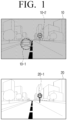
- FIG. 1 is a view for describing an image of a surrounding environment and a reference image for convenience of understanding of the disclosure.
- a vehicle may monitor a surrounding environment by using a sensor prepared in the vehicle.
- the vehicle may acquire an image 10 of a surrounding environment by capturing a route through which the vehicle is traveling, a surrounding environment, conditions of the road ahead by using a camera prepared in the vehicle.
- the camera herein is a component for capturing an event occurring on a traveling route of the vehicle, the surrounding environment of the vehicle, and the like and may be referred to as a sensor, a camera, or an image sensor, but hereinafter, these are collectively referred to as a camera for convenience of description.
- the vehicle may acquire the image 10 of the surrounding environment in which the vehicle is currently traveling by using the camera, and identify whether or not visibility of the image 10 of the surrounding environment satisfies a predetermined condition.
- the visibility herein may mean discrimination regarding the traffic sign information included in the image 10 of the surrounding environment. In an example, if the image 10 of the surrounding environment includes a road sign 10-2, the visibility may mean a degree that the road sign 10-2 is identifiable.
- the visibility according to an embodiment of the disclosure may mean to include discrimination, legibility, observability, and the like regarding the traffic sign information.
- the traffic sign information will be described in detail with reference to FIG. 3 .
- the visibility of the image 10 of the surrounding environment according to the disclosure satisfying the predetermined condition means low visibility of objects included in the image 10 of the surrounding environment for a vehicle driver.
- the vehicle generates an image in which the image 10 of the surrounding environment and a reference image 20 are merged, and control the driving of the vehicle based on the merged image.
- the vehicle idenitifies the road sign 20-1 from the reference image 20 and generates the merged image by using the identified road sign 20-1 and the image 10 of the surrounding environment.
- the reference image 20 may mean an image having high visibility stored in the vehicle in advance.
- the vehicle may identify the traffic sign information included in the image 10 of the surrounding environment captured while the vehicle travels through a route A according to the weather factor and the time factor, the vehicle may store the image 10 of the surrounding environment as the reference image 20. In this case, the vehicle may store location information of the route A together with the reference image 20.
- the reference image 20 which is an image having high visibility of the traffic sign information included in the route is not limited to an image captured through the camera prepared in the vehicle, and may be images acquired by various methods such as an image received from an external server, an image captured through another vehicle, and the like.
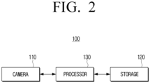
- FIG. 2 is a block diagram showing a configuration of the vehicle according to an embodiment of the disclosure.
- a vehicle 100 includes a camera 110, a storage 120, and a processor 130.
- the camera 110 may be disposed at a plurality of positions inside or outside of the vehicle 100.
- the vehicle 100 may capture the inside or outside of the vehicle 100 by using a plurality of cameras.
- the camera 110 may acquire the image 10 of the surrounding environment in which the vehicle 100 is currently traveling.
- the vehicle may acquire the image 10 of the surrounding environment in which traffic sign information and other traveling vehicles that are located and positioned ahead on the route through which the vehicle 100 is traveling are captured.
- the traffic sign info information herein may include at least one of a road sign, a lane, a speed bump, traffic lights, and road markings with words.
- the storage 120 stores an operating system (O/S) software module for driving the vehicle 100, a vehicle control module for a self-driving mode of the vehicle 100, various communication modules, an image analysis software module, and various pieces of data such as various contents.
- O/S operating system
- the storage 120 may be implemented as an internal memory such as a ROM or a RAM included in the processor 130 or may be implemented as a memory separated from the processor 130.
- the storage 120 may be implemented as a memory embedded in the vehicle 100 or may be implemented as a memory detachable from the vehicle 100 depending on the purpose of data storage. For example, data for driving the vehicle 100 may be stored in the memory embedded in the vehicle 100 and data for extension function of the vehicle 100 may be stored in the memory detachable from the vehicle 100.
- the memory embedded in the vehicle 100 may be implemented in a form of a non-volatile memory, a volatile memory, a hard disk drive (HDD), or a solid-state drive (SDD), and the memory detachable from the vehicle 100 may be implemented as a memory card (for example, a micro SD card or a USB memory) or an external memory (for example, a USB memory) connectable to a USB port.
- a memory card for example, a micro SD card or a USB memory
- an external memory for example, a USB memory
- the storage 120 may store the plurality of reference images 20 and location information corresponding to each of the plurality of reference images 20.
- the visibility of the image 10 of the surrounding environment acquired through the camera 110 during the traveling of the vehicle 100 is a degree that the traffic sign information included in the image 10 of the surrounding environment is identifiable
- the acquired image 10 of the surrounding environment may be stored as the reference image 20.
- the vehicle may also store location information corresponding to the image 10 of the surrounding environment.
- the plurality of reference images 20 may mean images stored in the storage 120 as images having high visibility among the images 10 of the surrounding environment acquired through the camera 110 prepared in the vehicle.
- the image having high visibility herein may mean an image in which the processor 130 may identify the traffic sign information included in the image 10 of the surrounding environment by analyzing the image 10 of the surrounding environment.
- an image in which the traffic sign information included in the image is identifiable by analyzing the image will be collectively referred to as the image having high visibility.
- a first image of the surrounding environment acquired during the daytime in a fine day may have relatively higher visibility than that of a second image of surrounding environment acquired at night in a cloudy day, and thus, the first image of the surrounding environment may be stored in the storage as the reference image 20.
- the plurality of reference images 20 stored in the storage 120 may be an image received from an external server, an image captured through another vehicle, and the like.
- the storage 120 may store a representative image indicating the traffic sign information.
- the traffic sign information may include at least one of a road sign, a lane, a speed bump, a crosswalk, traffic lights, and road markings with words.
- the lane from the traffic sign information included in the reference image 20 is identifiable but an unnecessary object is captured with the lane, the lane may be replaced with a lane of the representative image stored in the storage in a merged image. This will be described in detail with reference to FIG. 6 .
- the processor 130 may generally control the operations of the vehicle 100.
- the processor 130 may include one or more of a central processing unit (CPU)), a micro controller unit (MCU), a micro processing unit (MPU), a controller, an application processor (AP), or a communication processor (CP), and an ARM processor or may be defined as the corresponding term.
- the processor 130 may be implemented as a system on chip (SoC) or a large scale integration (LSI) in which a processing algorithm is embedded, or may be implemented as a field programmable gate array (FPGA).
- SoC system on chip
- LSI large scale integration
- FPGA field programmable gate array
- the processor 130 may acquire the image 10 of the surrounding environment in which the vehicle is currently traveling through the camera 110, and determine whether or not the visibility of the image 10 of the surrounding environment satisfies the predetermined condition.
- the processor 130 may analyze the image 10 of the surrounding environment, and if it is not possible to identify the traffic sign information included in the image 10 of the surrounding environment, it may be determined that the visibility of the image 10 of the surrounding environment satisfies the predetermined condition.
- the processor 130 may acquire the reference image 20 corresponding to a current location of the vehicle 100 among the plurality of reference images stored in the storage 120.
- the processor 130 may acquire an image in which the image 10 of the surrounding environment and the acquired reference image 20 are merged.
- the processor 130 may identify the traffic sign information in the acquired reference image 20 and generate the merged image by replacing a region in the image 10 of the surrounding environment corresponding to the identified traffic sign information with the identified traffic sign information.
- the image 10 of the surrounding environment may include an object identified through various types of sensors prepared in the vehicle 100 other than the camera 110.
- the vehicle may include at least one of a RADAR unit, a LIDAR unit, and an image sensor, and the processor 130 may acquire the image 10 of the surrounding environment based on an object identified through the RADAR unit, the LIDAR unit, the image sensor, or the like.
- the RADAR unit, the LIDAR unit, or the image sensor may detect a dynamic object located in a surrounding portion (for example, a vehicle, a pedestrian, a bicycle, or a motorcycle) during the traveling of the vehicle, and the processor may identify the image 10 of the surrounding environment based on the image acquired through the camera 110 and the dynamic object detected through the sensor.
- a surrounding portion for example, a vehicle, a pedestrian, a bicycle, or a motorcycle
- the processor 130 may control the driving of the vehicle 100 based on the merged image.
- the vehicle 100 may be implemented as a self-driving vehicle providing a self-driving mode and the vehicle 1000 may perform the self-driving of the vehicle 100 based on the merged image.
- the vehicle 100 in the related art performing the self-driving based on the mage 10 of the surrounding environment having low visibility had a problem that malfunctions frequently occurred due to failure of accurate recognition of road signs, lanes, and the like in the surrounding portion during the self-driving of the vehicle.
- the processor 130 may acquire an image in which the image 10 of the surrounding environment and the reference image 20 are merged and execute the self-driving based on the merged image by considering visibility during the execution of the self-driving, thereby significantly reducing a possibility of malfunctions.
- the processor 130 may update the reference image 20 with the image 10 of the surrounding environment and store the image in the storage 120.
- the processor 130 may compare the discrimination of the traffic sign information included in the image 10 of the surrounding environment and the discrimination of the traffic sign information included in the reference image with each other, and determine whether or not the visibility of the image 10 of the surrounding environment is higher than the visibility of the reference image 20 based on the compared result.
- the processor 130 may compare the visibility of the image 10 of the surrounding environment and the visibility of the reference image 20 with each other, when a predetermine period of time has elapsed from a point when the reference image 20 is generated. With the elapse of time, the traffic sign information such as a road sign, lanes, or a crosswalk on the road may be changed.
- the reference image 20 after the elapse of the predetermined period of time may not accurately reflect current traffic sign information with a high possibility, and accordingly, the processor 130 may determine whether or not the predetermined period of time has elapsed from a point when the reference image 20 is generated, and update the reference image 20, if the predetermined period of time has elapsed.
- the processor 130 may compare each visibility of the image 10 of the surrounding environment regarding the location A acquired through the camera 110 and the reference image 20. If the visibility of the image 10 of the surrounding environment is higher than the visibility of the reference image 20 according to the compared result, the image 10 of the surrounding environment may be stored in the storage 120 as the reference image 20. Accordingly, the updating of the reference image 20 corresponding to the location A may be executed.
- the vehicle 100 may further include a propulsion device, a power supply device, an input device, an output device, a traveling device, a sensing device, a communicator, a display, and the like.
- the propulsion device may include an engine/motor, an energy source, a transmission, and a wheel/tire.
- the engine/motor may be any combination of an internal combustion engine, an electric motor, a steam engine, and a stirling engine.
- the engine/motor may be implemented as a gasoline engine and an electric motor.
- the energy source may be a source of energy providing power to the engine/motor. That is, the engine/motor may convert the energy source into mechanical energy and use it for the propulsion of the vehicle 100.
- the energy source may be at least one of gasoline, diesel, propane, other gas-based fuels, ethanol, a solar panel, a battery, and other electric power source, and may be at least one of a fuel tank, a battery, a capacitor, and a flywheel.
- the transmission may transmit the mechanical power from the engine/motor to the wheel/tire.
- the transmission may include at least one of a gearbox, a clutch, a differential, and a drive shaft.
- the drive shafts may include one or more axles configured to be combined with the wheel/tire.
- the vehicle 100 may include one or more wheels/tires.
- the vehicle 100 may include two, three, four, or five or more wheels/tires, and thus, the vehicle 100 may be implemented as a two-wheeled vehicle, a three-wheeled vehicle, or four-wheeled vehicle.
- the wheel/tire may include at least one wheel fixedly attached to the transmission, and at least one tire which is combined with a rim of the wheel and may come into contact with a driving surface.
- the traveling device may include a brake, a steering, and a throttle.
- the steering may be a combination of mechanisms configured to adjust a direction of the self-driving vehicle.
- the throttle may be a combination of mechanisms configured to control a speed of the vehicle 100 by controlling an operation speed of the engine/motor.
- the throttle may adjust an amount of mixed gas in fuel air entering the engine/motor by adjusting an opening rate of the throttle, and may control the power and propulsion by adjusting the opening rate of the throttle.
- the brake may be a combination of mechanisms configured to decelerating the vehicle 100.
- the brake may use friction in order to reduce a speed of the wheel/tire.
- the sensing device may be implemented as a plurality of sensors detecting information regarding surrounding environment during the traveling of the vehicle 100.
- the sensing device may include a global positioning system (GPS), an inertial measurement unit (IMU) a RADAR unit, a LIDAR unit, and an image sensor.
- the sensing device may include at least one of a temperature/humidity sensor, an infrared sensor, an air pressure sensor, a proximity sensor, and an RGB sensor (illuminance sensor), but is not limited thereto, and may include various types of sensors detecting the information regarding the surrounding environment of the vehicle 100 and providing the information to a driver and the processor 130.
- the sensing device may include a movement sensing device capable of sensing a movement of the vehicle 100.
- the movement sensing device may include a magnetic sensor, an acceleration sensor, and a gyroscope sensor.
- the GPS is a component detecting a geographic location of the vehicle 100 and the processor 130 may also acquire location information detected through the GPS, when acquiring the image 10 of the surrounding environment and the reference image 20.
- the IMU may be a combination of sensors configured to detect a change of the location and direction of the vehicle 100 based on inertial acceleration.
- the combination of sensors may include accelerators and gyroscopes.
- the RADAR unit may be a sensor configured to detect objects in the environment in which the vehicle 100 is located, by using a wireless signal.
- the RADAR unit may be configured to detect speeds and/or directions of the obj ects.
- the LIDAR unit may be a sensor configured to detect objects in the environment in which the vehicle 100 is located, by using a laser.
- the peripheral device may include a navigation system, headlights, winkers, wipers, interior lights, a heater, an air conditioner, and the like.
- the navigation system may be a system configured to determine the driving route of the vehicle 100.
- the navigation system may be configured to update the driving route dynamically while the vehicle 100 is traveling.
- the navigation system may use data from the GPS and maps in order to determine the driving route of the vehicle 100.
- the vehicle may provide the merged image through the navigation system.
- the vehicle 100 may display the merged image on a display included in the navigation system.
- a driver receives an image having ensured high visibility of the traffic sign information through the navigation system, thereby increasing convenience during the driving of the vehicle.
- the communicator may execute communication with an external device.
- the communicator may execute communication with an external server with a wired/wireless communication system, and a communication system such as BlueTooth (BT), Wireless Fidelity (WI-FI), Zigbee, Infrared (IR), Serial Interface, Universal Serial Bus (USB), NFC (Near Field Communication), V2X (Vehicle to Everything), mobile communication (Cellular) may be used.
- BT BlueTooth
- WI-FI Wireless Fidelity
- IR Infrared
- USB Universal Serial Bus
- NFC Near Field Communication
- V2X Vehicle to Everything
- Cellular Cellular
- the communicator may acquire the traffic sign information corresponding to the current location of the vehicle 100 from an external server and the processor 130 may generate an image by adding the traffic sign information received through the communicator to the merged image.
- the communicator may receive various pieces of information relating to current location, route, and the like that the vehicle 100 is traveling, from an external server.
- the communicator may receive weather information, news information, road condition information, and the like from an external server.
- the road condition information may mean condition information regarding a route (or road) through which the vehicle 100 is traveling.
- the communicator may receive various pieces of information such as road surface condition information, traffic condition information, traffic accident information, traffic enforcement information, and the like.
- the processor 130 may provide the received road condition information to a driver with the merged image.
- the processor 130 may execute the self-driving of the vehicle 100 based on the merged image and the received road condition information in the self-driving mode.
- the display may include at least one of a liquid crystal display, a thin film transistor-liquid crystal display, an organic light-emitting diode, a flexible display, a see-through display, a 3D display, and a head up display (UHD).
- a liquid crystal display a thin film transistor-liquid crystal display, an organic light-emitting diode, a flexible display, a see-through display, a 3D display, and a head up display (UHD).
- the display may be implemented as a display included in the navigation system prepared in the vehicle 100 or may be implemented as a HUD displaying vehicle driving information in a region of a windshield.
- the vehicle 100 may include a plurality of displays depending on the implementation forms.
- the display is assumed to be implemented as the HUD and this will be described in more detail with reference to FIG. 5 .
- the processor 130 may provide the merged image through the display. However, there is no limitation thereto, and the processor 130 may display only the identified traffic sign information from the reference image 20 corresponding to the current location. In an example, the processor 130 may merge the identified traffic sign information with the image 10 of the surrounding environment and display the merged image, or may display only the identified traffic sign information at a corresponding position on the windshield of the vehicle in an augmented reality (AR mode).
- AR mode augmented reality
- the processor 130 may acquire images of portions right and left of, and behind the vehicle 100, in addition to a portion ahead of the vehicle 100 through the camera 110.
- the processor 130 may generate the image 10 of the surrounding environment based on the image acquired through the camera 110 and the dynamic object acquired through various types of sensors prepared in the vehicle.
- the image 10 of the surrounding environment may not only a 2D image obtained by capturing only a portion ahead of the vehicle 100, but also a 3D image obtained by capturing a surrounding environment of the vehicle 100 with a 360-degree field of view based on the images of portions right and left of, and behind the vehicle.
- the processor 130 may provide the merged image by rendering a dynamic object (for example, neighboring vehicles, pedestrians, and the like) detected through various types of sensors prepared in the vehicle 100 in a 3D format on the image 10 of the surrounding environment.
- a dynamic object for example, neighboring vehicles, pedestrians, and the like
- FIGS. 3A and 3B are views for describing a method for acquiring a merged image according to an embodiment of the disclosure.
- the visibility may be low due to the weather factor and the time factor during the traveling of the vehicle 100.
- the visibility may be difficult to identify the road sign 10-2 and a traveling vehicle 10-1 located in portions ahead of the vehicle 100, and this may increase the risk of an accident.
- the visibility of the image 10 of the surrounding environment acquired through the camera 110 is inversely proportional to a failure rate of the self-driving.
- the self-driving vehicle determining the traveling route based on the image 10 of the surrounding environment may execute the self-driving at a low failure rate.
- the self-driving vehicle may execute the self-driving at a high failure rate.
- the reference image 20 corresponding to the location of the vehicle 100 is acquired, the traffic sign information included in the reference image 20 is identified and merged with the image 10 of the surrounding environment, and the driving of the vehicle 100 is controlled based on the merged image.
- the reference image corresponding to the current location of the vehicle 100 may be an image in which the traffic sign information such as the road sign 20-1 is identifiable.
- the traffic sign information may mean not information changing in real time, but fixed information such as the road sign 20-1, a lane, a crosswalk, a speed bump, and road markings with words.
- the information changing in real time is information such as the traveling vehicle 10-1 included in the image 10 of the surrounding environment and information regarding the traveling vehicle 10-1 needs to be identified from the image 10 of the surrounding environment acquired through the camera 110 at the current time, not from the reference image 20.
- the vehicle 100 may acquire real-time information (for example, the traveling vehicle 10-1) from the image 10 of the traveling environment shown in (a) of FIG. 3A and acquire the traffic sign information from the reference image 20 shown in (b).
- the vehicle may acquire a merged image 30 in which the acquired image 10 of the traveling environment and the traffic sign information are merged.
- the vehicle may generate a merged image by replacing the corresponding region on the image 10 of the surrounding environment based on the identified traffic sign information, with the identified traffic sign information.
- the merged image may be expressed as shown in (c) of FIG. 3A .
- the merged image may include the traveling vehicle 10-1 and the road sign 20-1.
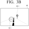
- the vehicle 100 may acquire a rendered image 40 by executing rendering of the merged image 30 as shown in FIG. 3B .
- the vehicle 100 may determine a traveling route in a self-driving mode based on the merged image 30.
- the vehicle 100 acquires a the rendered image 40 obtained by removing factors other than important factors for determining the traveling route from the merged image 30.
- the important factors herein are the traveling vehicle 10-1, the traffic sign information such as lanes or the road sign 20-1, and the dynamic object (for example, a pedestrian, a motorcycle, or a bicycle) which affects the determination of the traveling route.
- the rendered image 40 according to an embodiment of the disclosure is advantageous in terms of a smaller size than that of the merged image 30 and reducing the failure rate to be lower than that of the merged image when determining the traveling route of the vehicle 100 in the self-driving mode.
- FIGS. 4 and 5 are views for describing a method for displaying the merged image according to an embodiment of the disclosure.
- the vehicle 100 may provide the merged image 30 to a driver, in addition to the use of the merged image 30 or the rendered image 40 in order to determine the self-driving route in the self-driving mode.
- the vehicle 100 may display the merged image 30 on a display prepared on a dashboard or a navigation system of the vehicle 100.
- a driver may drive the vehicle with the displayed merged image 30, although a road sign 410 and traveling vehicles 420 and 430 are limitedly identified through the windshield due to the weather factor or the time factor.
- the merged image 30 may be provided only in a manual driving mode of the vehicle 100, but is not limited thereto, and the vehicle 100 may execute the self-driving based on the merged image 30 or the rendered image 40 in the self-driving mode, and display the merged image 30 or the rendered image 40 at the same time.
- the merged image 30 or the rendered image 40 may be provided to a driver through the HUD display.
- the vehicle 100 may display the identified traffic sign information using the AR mode.
- the vehicle 100 may display the road sign 410 acquired from the reference image 20 at a position corresponding to the road sign 410 on the windshield.
- a driver may receive the traffic sign information through the windshield without any limitation due to the weather factor or the time factor.
- FIG. 6 is a view for describing a method for acquiring a merged image according to another embodiment of the disclosure.
- the vehicle 100 may store a representative image corresponding to each traffic sign information.
- a representative image corresponding to a "Stop" road sign may be stored in the vehicle 100 in advance.
- the vehicle 100 may replace the "Stop" road sign with the representative image in the merged image 30.
- the traffic sign information included in the merged image 30 is acquired from the reference image 20, and if unnecessary information (for example, graffiti) is included around the traffic sign information on the reference image 20, the traffic sign information included in the merged image 30 may include the unnecessary information as it is.
- the vehicle 100 may identify the traffic sign information in the merged image 30 and perform rendering to replace the identified traffic sign information with each corresponding representative image.
- the "Stop" road sign 30-1 included in the merged image 30 includes unnecessary information, but a "Stop” road sign 40-1 included in the rendered image 40 may be replaced with the representative image.
- FIG. 7 is a flowchart for describing a method for controlling a vehicle according to an embodiment of the disclosure.
- an image of a surrounding environment in which a vehicle is currently traveling is acquired (S710).
- a reference image corresponding to a current location of the vehicle is acquired among a plurality of reference images (S730).
- An image in which the image of the surrounding environment and the reference image are merged is acquired (S740).
- the driving of the vehicle is controlled based on the merged image (S750).
- Step S740 of acquiring the merged image may include identifying traffic sign information included in the reference image, and generating a merged image by replacing a corresponding region in the image of the surrounding environment with the identified traffic sign information.
- the traffic sign information may include at least one of a road sign, a lane, a speed bump, traffic lights, and road markings with words.
- the vehicle may store a representative image indicating the traffic sign information, and in Step S740 of acquiring the merged image, a representative image corresponding to at least one piece of the traffic sign information included in the merged image may be acquired, and the at least one piece of the traffic sign information may be replaced with the acquired representative image.
- the control method may further include acquiring traffic sign information corresponding to a current location from an external server, and adding the traffic sign information acquired from the external server to the merged image.
- the vehicle may include a head up display (HUD) and the control method may further include providing at least one of the merged image and the identified traffic sign information through the HUD.
- HUD head up display
- the control method may further include, based on visibility of the image of the surrounding environment being higher than visibility of the reference image corresponding to current position information, updating the reference image with the image of the surrounding environment.
- the control method may further include comparing visibility of the image of the surrounding environment and visibility of the reference image, after a predetermined period of time elapsed from a point when the reference image is generated, and based on visibility of the image of the surrounding environment being higher than visibility of the reference image, updating the reference image with the image of the surrounding environment.
- Step S750 of controlling driving of the vehicle may include, based on the vehicle being in a self-driving mode, executing self-driving based on the merged image, and based on the vehicle being in a manual driving mode, providing at least one of the merged image and the identified traffic sign information through the HUD.
- At least some configurations of the methods according to embodiments of the disclosure described above may be implemented in a form of an application installable in the existing electronic device.
- the embodiments described above may be implemented in a recording medium readable by a computer or a similar device using software, hardware, or a combination thereof.
- the embodiments described in this specification may be implemented as a processor itself.
- the embodiments such as procedures and functions described in this specification may be implemented as software modules. Each of the software modules may execute one or more functions and operations described in this specification.
- Computer instructions for executing processing operations according to the embodiments of the disclosure descried above may be stored in a non-transitory computer-readable medium.
- the computer instructions stored in such a non-transitory computer-readable medium are executed by the processor, the computer instructions may enable a specific machine to execute the processing operations according to the embodiments described above.
- the non-transitory computer-readable medium is not a medium storing data for a short period of time such as a register, a cache, or a memory, but means a medium that semi-permanently stores data and is readable by a machine.
- Specific examples of the non-transitory computer-readable medium may include a CD, a DVD, a hard disk, a Blu-ray disc, a USB, a memory card, and a ROM.
Landscapes
- Engineering & Computer Science (AREA)
- Mechanical Engineering (AREA)
- Transportation (AREA)
- Multimedia (AREA)
- Physics & Mathematics (AREA)
- Automation & Control Theory (AREA)
- General Physics & Mathematics (AREA)
- Chemical & Material Sciences (AREA)
- Combustion & Propulsion (AREA)
- Theoretical Computer Science (AREA)
- Human Computer Interaction (AREA)
- Data Mining & Analysis (AREA)
- Optics & Photonics (AREA)
- Mathematical Physics (AREA)
- Life Sciences & Earth Sciences (AREA)
- Bioinformatics & Computational Biology (AREA)
- Computer Vision & Pattern Recognition (AREA)
- Evolutionary Biology (AREA)
- Evolutionary Computation (AREA)
- General Engineering & Computer Science (AREA)
- Bioinformatics & Cheminformatics (AREA)
- Artificial Intelligence (AREA)
- Traffic Control Systems (AREA)
- Aviation & Aerospace Engineering (AREA)
- Radar, Positioning & Navigation (AREA)
- Remote Sensing (AREA)
Description
- The disclosure relates to a vehicle and a method for controlling the same, and more particularly relates to a vehicle providing a self-driving mode and a method for controlling the same.
- Recently, according to the growing interest in self-driving vehicles, the related technologies are actively researched and developed. An example of such technology is disclosed by the document
EP 3130891 A1 (CONTINENTAL AUTOMOTIVE GMBH) published on 15 February 2017 . - In particular, although a self-driving vehicle identifies a traveling route based on information regarding a surrounding environment of the vehicle, there were problems that the vehicle was not able to accurately identify a traveling route or malfunctions frequently occurred due to failure of accurate recognition of the surrounding environment of the vehicle.
- For example, although it is a route through which the vehicle traveled safe in the past, there was a problem that the self-driving function is disabled due to failure of recognition of the traveling route according to weather factors such as snow, rain, fog, and the like and a time factor such as night.
- Therefore, it was necessary to develop a method for acquiring surrounding environment information of the vehicle independently from the weather factor or the time factor and identifying the traveling route.
- The disclosure has been made to address the aforementioned needs, and provides a vehicle capable of providing an image having improved visibility of a road sign and the like and performing self-driving based on this, and a method for controlling the same.
- According to an embodiment of the disclosure for achieving the above-mentioned object, there is provided a vehicle according to claim 1.
- The processor may be configured to identify traffic sign information included in the reference image, and generate a merged image by replacing a corresponding region in the image of the surrounding environment with the identified traffic sign information.
- The traffic sign information may include at least one of a road sign, a lane, a speed bump, traffic lights, and road markings with words.
- A storage may store a representative image indicating the traffic sign information, and the processor may be configured to acquire a representative image corresponding to at least one piece of traffic sign information included in the merged image, and replace the at least one piece of traffic sign information with the acquired representative image.
- The vehicle may further include a communicator, and the processor is configured to acquire traffic sign information corresponding to the current location from an external server through the communicator, and add the traffic sign information acquired from the external server to the merged image.
- The vehicle may further include a head up display (HUD), and the processor may be configured to provide at least one of the merged image and the identified traffic sign information through the HUD.
- The vehicle may further include a head up display (HUD), and the processor may be configured to acquire a rendered image by performing rendering of the merged image, store the rendered image in the storage, and provide the rendered image through the HUD, and the rendered image may be an image generated by identifying a dynamic object and the traffic sign information in the merged image. The processor may be configured to, based on visibility of the image of the surrounding environment being higher than visibility of the reference image corresponding to current location information, update the reference image with the image of the surrounding environment.
- The processor may be configured to compare visibility of the image of the surrounding environment and visibility of the reference image, after a predetermined period of time elapsed from a point when the reference image is generated, and based on visibility of the image of the surrounding environment being higher than visibility of the reference image, updating the reference image with the image of the surrounding environment.
- The vehicle may further include a head up display (HUD), and the processor may be configured to, based on the vehicle being in a self-driving mode, executing self-driving based on the merged image, and based on the vehicle being in a manual driving mode, providing at least one of the merged image and the identified traffic sign information through the HUD.
- According to another embodiment of the disclosure, there is provided a method for controlling a vehicle according to claim 11.
- The acquiring a merged image may include identifying traffic sign information included in the reference image, and generating a merged image by replacing a corresponding region in the image of the surrounding environment with the identified traffic sign information.
- The traffic sign information may include at least one of a road sign, a lane, a speed bump, traffic lights, and road markings with words.
- The vehicle may store a representative image indicating the traffic sign information, and the acquiring a merged image may include acquiring a representative image corresponding to at least one piece of traffic sign information included in the merged image, and replacing the at least one piece of traffic sign information with the acquired representative image.
- The method may further include acquiring traffic sign information corresponding to the current location from an external server, and adding the traffic sign information acquired from the external server to the merged image.
- The vehicle may include a head up display (HUD), and the method may further include providing at least one of the merged image and the identified traffic sign information through the HUD.
- The method may further include, based on visibility of the image of the surrounding environment being higher than visibility of the reference image corresponding to current location information, updating the reference image with the image of the surrounding environment.
- The method may further include comparing visibility of the image of the surrounding environment and visibility of the reference image, after a predetermined period of time elapsed from a point when the reference image is generated, and based on visibility of the image of the surrounding environment being higher than visibility of the reference image, updating the reference image with the image of the surrounding environment.
- The controlling driving of the vehicle may include, based on the vehicle being in a self-driving mode, executing self-driving based on the merged image, and based on the vehicle being in a manual driving mode, providing at least one of the merged image and the identified traffic sign information through the HUD.
- According to still another embodiment of the disclosure which is not claimed, there is provided a non-transitory computer-readable medium storing computer instructions to, based on computer instructions being executed by a processor of a vehicle, enable the vehicle to execute operations, in which the operations may include acquiring an image of a surrounding environment in which the vehicle is currently traveling, based on visibility of the image of the surrounding environment satisfying a predetermined condition, acquiring a reference image corresponding to a current location of the vehicle among the plurality of reference images, acquiring an image in which the image of the surrounding environment and the reference image are merged, and controlling driving of the vehicle based on the merged image.
- According to the embodiments of the disclosure described above, the image having improved visibility of the traffic sign information may be acquired and a failure rate may be reduced during the self-driving.
-
-
FIG. 1 is a view for describing an image of a surrounding environment and a reference image for convenience of understanding. -
FIG. 2 is a block diagram showing a configuration of a vehicle according to an embodiment. -
FIGS. 3A and 3B are views for describing a method for acquiring a merged image according to an embodiment. -
FIGS. 4 and5 are views for describing a method for displaying the merged image according to an embodiment. -
FIG. 6 is a view for describing a method for acquiring a merged image according to another embodiment. -
FIG. 7 is a flowchart for describing a method for controlling a vehicle according to an embodiment. - -
- The disclosure will be described in detail after briefly explaining the terms used in the specification.
- The terms used in embodiments of the disclosure have been selected as widely used general terms as possible in consideration of functions in the disclosure, but these may vary in accordance with the intention of those skilled in the art, the precedent, the emergence of new technologies and the like. In addition, in a certain case, there is also a term arbitrarily selected by the applicant, in which case the meaning will be described in detail in the description of the disclosure. Therefore, the terms used in the disclosure should be defined based on the meanings of the terms themselves and the contents throughout the disclosure, rather than the simple names of the terms.
- The embodiments of the disclosure may be variously changed and include various embodiments, and specific embodiments will be shown in the drawings and described in detail in the description. However, it should be understood that this is not to limit the scope of the specific embodiments and all modifications, equivalents, and/or alternatives included in the disclosed spirit and technical scope are included. In describing the disclosure, a detailed description of the related art is omitted when it is determined that the detailed description may unnecessarily obscure a gist of the disclosure.
- The terms "first," "second," or the like may be used for describing various elements but the elements may not be limited by the terms. The terms are used only to distinguish one element from another.
- Unless otherwise defined specifically, a singular expression may encompass a plural expression. It is to be understood that the terms such as "comprise" or "consist of" are used herein to designate a presence of characteristic, number, step, operation, element, part, or a combination thereof, and not to preclude a presence or a possibility of adding one or more of other characteristics, numbers, steps, operations, elements, parts or a combination thereof.
- A term such as "module" or a "unit" in the disclosure may perform at least one function or operation, and may be implemented as hardware, software, or a combination of hardware and software. Further, except for when each of a plurality of "modules", "units", and the like needs to be realized in an individual hardware, the components may be integrated in at least one module and be implemented in at least one processor (not shown).
- Hereinafter, with reference to the accompanying drawings, embodiments of the disclosure will be described in detail so that those skilled in the art can easily make and use the embodiments in the technical field to which to which the disclosure belongs. But, the disclosure may be implemented in various different forms and is not limited to the embodiments described herein. In addition, in the drawings, the parts not relating to the description are omitted for clearly describing the disclosure, and the same reference numerals are used for the same parts throughout the specification.
-
FIG. 1 is a view for describing an image of a surrounding environment and a reference image for convenience of understanding of the disclosure. - Referring to
FIG. 1 , a vehicle according to an embodiment of the disclosure may monitor a surrounding environment by using a sensor prepared in the vehicle. In an example, the vehicle may acquire animage 10 of a surrounding environment by capturing a route through which the vehicle is traveling, a surrounding environment, conditions of the road ahead by using a camera prepared in the vehicle. The camera herein is a component for capturing an event occurring on a traveling route of the vehicle, the surrounding environment of the vehicle, and the like and may be referred to as a sensor, a camera, or an image sensor, but hereinafter, these are collectively referred to as a camera for convenience of description. - The vehicle according to an embodiment of the disclosure may acquire the
image 10 of the surrounding environment in which the vehicle is currently traveling by using the camera, and identify whether or not visibility of theimage 10 of the surrounding environment satisfies a predetermined condition. The visibility herein may mean discrimination regarding the traffic sign information included in theimage 10 of the surrounding environment. In an example, if theimage 10 of the surrounding environment includes a road sign 10-2, the visibility may mean a degree that the road sign 10-2 is identifiable. The visibility according to an embodiment of the disclosure may mean to include discrimination, legibility, observability, and the like regarding the traffic sign information. The traffic sign information will be described in detail with reference toFIG. 3 . - The visibility of the
image 10 of the surrounding environment according to the disclosure satisfying the predetermined condition means low visibility of objects included in theimage 10 of the surrounding environment for a vehicle driver. For example, a case where the road sign 10-2 included in theimage 10 of the surrounding environment is not identified due to the weather factors such as snow, rain, fog, smog and the like and a time factor such as night and the meaning of the road sign 10-2, a word, a shape, a form, and the like of the road sign 10-2, and the like is not recognized, may correspond to a case where the predetermined condition are satisfied. - Referring to
FIG. 1 , it may be confirmed that the visibility of the traffic sign information included in theimage 10 of the surrounding environment deteriorates and, particularly, the road sign 10-2 may not be identified. In this case, the vehicle generates an image in which theimage 10 of the surrounding environment and areference image 20 are merged, and control the driving of the vehicle based on the merged image. In an example, the vehicle idenitifies the road sign 20-1 from thereference image 20 and generates the merged image by using the identified road sign 20-1 and theimage 10 of the surrounding environment. - The
reference image 20 may mean an image having high visibility stored in the vehicle in advance. In an example, when the vehicle may identify the traffic sign information included in theimage 10 of the surrounding environment captured while the vehicle travels through a route A according to the weather factor and the time factor, the vehicle may store theimage 10 of the surrounding environment as thereference image 20. In this case, the vehicle may store location information of the route A together with thereference image 20. However, there is no limitation thereto, and thereference image 20 which is an image having high visibility of the traffic sign information included in the route is not limited to an image captured through the camera prepared in the vehicle, and may be images acquired by various methods such as an image received from an external server, an image captured through another vehicle, and the like. - Hereinabove, the operation of acquiring the merged image by using the
image 10 of the surrounding environment and thereference image 20 by the vehicle has been briefly described. Hereinafter, a method for controlling the driving of the vehicle by acquiring the merged image by the vehicle will be described in detail. -
FIG. 2 is a block diagram showing a configuration of the vehicle according to an embodiment of the disclosure. - Referring to
FIG. 2 , avehicle 100 includes acamera 110, astorage 120, and aprocessor 130. - The
camera 110 may be disposed at a plurality of positions inside or outside of thevehicle 100. In this case, thevehicle 100 may capture the inside or outside of thevehicle 100 by using a plurality of cameras. - In particular, the
camera 110 according to an embodiment of the disclosure may acquire theimage 10 of the surrounding environment in which thevehicle 100 is currently traveling. In an example, the vehicle may acquire theimage 10 of the surrounding environment in which traffic sign information and other traveling vehicles that are located and positioned ahead on the route through which thevehicle 100 is traveling are captured. The traffic sign info information herein may include at least one of a road sign, a lane, a speed bump, traffic lights, and road markings with words. - The
storage 120 stores an operating system (O/S) software module for driving thevehicle 100, a vehicle control module for a self-driving mode of thevehicle 100, various communication modules, an image analysis software module, and various pieces of data such as various contents. - The
storage 120 may be implemented as an internal memory such as a ROM or a RAM included in theprocessor 130 or may be implemented as a memory separated from theprocessor 130. In this case, thestorage 120 may be implemented as a memory embedded in thevehicle 100 or may be implemented as a memory detachable from thevehicle 100 depending on the purpose of data storage. For example, data for driving thevehicle 100 may be stored in the memory embedded in thevehicle 100 and data for extension function of thevehicle 100 may be stored in the memory detachable from thevehicle 100. The memory embedded in thevehicle 100 may be implemented in a form of a non-volatile memory, a volatile memory, a hard disk drive (HDD), or a solid-state drive (SDD), and the memory detachable from thevehicle 100 may be implemented as a memory card (for example, a micro SD card or a USB memory) or an external memory (for example, a USB memory) connectable to a USB port. - Particularly, the
storage 120 may store the plurality ofreference images 20 and location information corresponding to each of the plurality ofreference images 20. In an example, if the visibility of theimage 10 of the surrounding environment acquired through thecamera 110 during the traveling of thevehicle 100 is a degree that the traffic sign information included in theimage 10 of the surrounding environment is identifiable, the acquiredimage 10 of the surrounding environment may be stored as thereference image 20. In this case, the vehicle may also store location information corresponding to theimage 10 of the surrounding environment. - The plurality of
reference images 20 according to an embodiment of the disclosure may mean images stored in thestorage 120 as images having high visibility among theimages 10 of the surrounding environment acquired through thecamera 110 prepared in the vehicle. The image having high visibility herein may mean an image in which theprocessor 130 may identify the traffic sign information included in theimage 10 of the surrounding environment by analyzing theimage 10 of the surrounding environment. Hereinafter, for convenience of description, an image in which the traffic sign information included in the image is identifiable by analyzing the image will be collectively referred to as the image having high visibility. - In an example, a first image of the surrounding environment acquired during the daytime in a fine day may have relatively higher visibility than that of a second image of surrounding environment acquired at night in a cloudy day, and thus, the first image of the surrounding environment may be stored in the storage as the
reference image 20. However, there is no limitation thereto, and the plurality ofreference images 20 stored in thestorage 120 may be an image received from an external server, an image captured through another vehicle, and the like. - The
storage 120 according to an embodiment of the disclosure may store a representative image indicating the traffic sign information. The traffic sign information may include at least one of a road sign, a lane, a speed bump, a crosswalk, traffic lights, and road markings with words. In an example, if the lane from the traffic sign information included in thereference image 20 is identifiable but an unnecessary object is captured with the lane, the lane may be replaced with a lane of the representative image stored in the storage in a merged image. This will be described in detail with reference toFIG. 6 . - The
processor 130 may generally control the operations of thevehicle 100. - According to an embodiment, the
processor 130 may include one or more of a central processing unit (CPU)), a micro controller unit (MCU), a micro processing unit (MPU), a controller, an application processor (AP), or a communication processor (CP), and an ARM processor or may be defined as the corresponding term. In addition, theprocessor 130 may be implemented as a system on chip (SoC) or a large scale integration (LSI) in which a processing algorithm is embedded, or may be implemented as a field programmable gate array (FPGA). - In particular, the
processor 130 may acquire theimage 10 of the surrounding environment in which the vehicle is currently traveling through thecamera 110, and determine whether or not the visibility of theimage 10 of the surrounding environment satisfies the predetermined condition. In an example, theprocessor 130 may analyze theimage 10 of the surrounding environment, and if it is not possible to identify the traffic sign information included in theimage 10 of the surrounding environment, it may be determined that the visibility of theimage 10 of the surrounding environment satisfies the predetermined condition. In this case, theprocessor 130 may acquire thereference image 20 corresponding to a current location of thevehicle 100 among the plurality of reference images stored in thestorage 120. - The
processor 130 may acquire an image in which theimage 10 of the surrounding environment and the acquiredreference image 20 are merged. In an example, theprocessor 130 may identify the traffic sign information in the acquiredreference image 20 and generate the merged image by replacing a region in theimage 10 of the surrounding environment corresponding to the identified traffic sign information with the identified traffic sign information. However, there is no limitation thereto, and theimage 10 of the surrounding environment may include an object identified through various types of sensors prepared in thevehicle 100 other than thecamera 110. In an example, the vehicle may include at least one of a RADAR unit, a LIDAR unit, and an image sensor, and theprocessor 130 may acquire theimage 10 of the surrounding environment based on an object identified through the RADAR unit, the LIDAR unit, the image sensor, or the like. According to an embodiment, the RADAR unit, the LIDAR unit, or the image sensor may detect a dynamic object located in a surrounding portion (for example, a vehicle, a pedestrian, a bicycle, or a motorcycle) during the traveling of the vehicle, and the processor may identify theimage 10 of the surrounding environment based on the image acquired through thecamera 110 and the dynamic object detected through the sensor. - The
processor 130 may control the driving of thevehicle 100 based on the merged image. In an example, thevehicle 100 may be implemented as a self-driving vehicle providing a self-driving mode and the vehicle 1000 may perform the self-driving of thevehicle 100 based on the merged image. Thevehicle 100 in the related art performing the self-driving based on themage 10 of the surrounding environment having low visibility had a problem that malfunctions frequently occurred due to failure of accurate recognition of road signs, lanes, and the like in the surrounding portion during the self-driving of the vehicle. - The
processor 130 according to an embodiment of the disclosure may acquire an image in which theimage 10 of the surrounding environment and thereference image 20 are merged and execute the self-driving based on the merged image by considering visibility during the execution of the self-driving, thereby significantly reducing a possibility of malfunctions. - If the visibility of the
image 10 of the surrounding environment is higher than the visibility of thereference image 20 corresponding to current location information, theprocessor 130 according to an embodiment of the disclosure may update thereference image 20 with theimage 10 of the surrounding environment and store the image in thestorage 120. Theprocessor 130 may compare the discrimination of the traffic sign information included in theimage 10 of the surrounding environment and the discrimination of the traffic sign information included in the reference image with each other, and determine whether or not the visibility of theimage 10 of the surrounding environment is higher than the visibility of thereference image 20 based on the compared result. - The
processor 130 according to another embodiment of the disclosure may compare the visibility of theimage 10 of the surrounding environment and the visibility of thereference image 20 with each other, when a predetermine period of time has elapsed from a point when thereference image 20 is generated. With the elapse of time, the traffic sign information such as a road sign, lanes, or a crosswalk on the road may be changed. Thereference image 20 after the elapse of the predetermined period of time may not accurately reflect current traffic sign information with a high possibility, and accordingly, theprocessor 130 may determine whether or not the predetermined period of time has elapsed from a point when thereference image 20 is generated, and update thereference image 20, if the predetermined period of time has elapsed. In an example, if the vehicle is traveling a location A and thereference image 20 corresponding to the location A is an image after the elapse of the predetermined period of time from the generation point, theprocessor 130 may compare each visibility of theimage 10 of the surrounding environment regarding the location A acquired through thecamera 110 and thereference image 20. If the visibility of theimage 10 of the surrounding environment is higher than the visibility of thereference image 20 according to the compared result, theimage 10 of the surrounding environment may be stored in thestorage 120 as thereference image 20. Accordingly, the updating of thereference image 20 corresponding to the location A may be executed. - The
vehicle 100 according to an embodiment of the disclosure may further include a propulsion device, a power supply device, an input device, an output device, a traveling device, a sensing device, a communicator, a display, and the like. - The propulsion device may include an engine/motor, an energy source, a transmission, and a wheel/tire.
- The engine/motor may be any combination of an internal combustion engine, an electric motor, a steam engine, and a stirling engine. In an example, if the
vehicle 100 is a gas-electric hybrid car, the engine/motor may be implemented as a gasoline engine and an electric motor. - The energy source may be a source of energy providing power to the engine/motor. That is, the engine/motor may convert the energy source into mechanical energy and use it for the propulsion of the
vehicle 100. The energy source may be at least one of gasoline, diesel, propane, other gas-based fuels, ethanol, a solar panel, a battery, and other electric power source, and may be at least one of a fuel tank, a battery, a capacitor, and a flywheel. - The transmission may transmit the mechanical power from the engine/motor to the wheel/tire. For example, the transmission may include at least one of a gearbox, a clutch, a differential, and a drive shaft. When the transmission includes drive shafts, the drive shafts may include one or more axles configured to be combined with the wheel/tire.
- The
vehicle 100 may include one or more wheels/tires. In an example, thevehicle 100 may include two, three, four, or five or more wheels/tires, and thus, thevehicle 100 may be implemented as a two-wheeled vehicle, a three-wheeled vehicle, or four-wheeled vehicle. The wheel/tire may include at least one wheel fixedly attached to the transmission, and at least one tire which is combined with a rim of the wheel and may come into contact with a driving surface. - The traveling device may include a brake, a steering, and a throttle.
- The steering may be a combination of mechanisms configured to adjust a direction of the self-driving vehicle.
- The throttle may be a combination of mechanisms configured to control a speed of the
vehicle 100 by controlling an operation speed of the engine/motor. In addition, the throttle may adjust an amount of mixed gas in fuel air entering the engine/motor by adjusting an opening rate of the throttle, and may control the power and propulsion by adjusting the opening rate of the throttle. - The brake may be a combination of mechanisms configured to decelerating the
vehicle 100. For example, the brake may use friction in order to reduce a speed of the wheel/tire. - The sensing device may be implemented as a plurality of sensors detecting information regarding surrounding environment during the traveling of the
vehicle 100. In an example, the sensing device may include a global positioning system (GPS), an inertial measurement unit (IMU) a RADAR unit, a LIDAR unit, and an image sensor. In addition, the sensing device may include at least one of a temperature/humidity sensor, an infrared sensor, an air pressure sensor, a proximity sensor, and an RGB sensor (illuminance sensor), but is not limited thereto, and may include various types of sensors detecting the information regarding the surrounding environment of thevehicle 100 and providing the information to a driver and theprocessor 130. - In addition, the sensing device may include a movement sensing device capable of sensing a movement of the
vehicle 100. The movement sensing device may include a magnetic sensor, an acceleration sensor, and a gyroscope sensor. - The GPS is a component detecting a geographic location of the
vehicle 100 and theprocessor 130 may also acquire location information detected through the GPS, when acquiring theimage 10 of the surrounding environment and thereference image 20. - The IMU may be a combination of sensors configured to detect a change of the location and direction of the
vehicle 100 based on inertial acceleration. For example, the combination of sensors may include accelerators and gyroscopes. - The RADAR unit may be a sensor configured to detect objects in the environment in which the
vehicle 100 is located, by using a wireless signal. In addition, the RADAR unit may be configured to detect speeds and/or directions of the obj ects. - The LIDAR unit may be a sensor configured to detect objects in the environment in which the
vehicle 100 is located, by using a laser. - The peripheral device may include a navigation system, headlights, winkers, wipers, interior lights, a heater, an air conditioner, and the like.
- The navigation system may be a system configured to determine the driving route of the
vehicle 100. The navigation system may be configured to update the driving route dynamically while thevehicle 100 is traveling. For example, the navigation system may use data from the GPS and maps in order to determine the driving route of thevehicle 100. - In particular, the vehicle according to an embodiment of the disclosure may provide the merged image through the navigation system. In an example, if the
vehicle 100 is in a manual driving mode, thevehicle 100 may display the merged image on a display included in the navigation system. In this case, a driver receives an image having ensured high visibility of the traffic sign information through the navigation system, thereby increasing convenience during the driving of the vehicle. - The communicator may execute communication with an external device. In an example, the communicator may execute communication with an external server with a wired/wireless communication system, and a communication system such as BlueTooth (BT), Wireless Fidelity (WI-FI), Zigbee, Infrared (IR), Serial Interface, Universal Serial Bus (USB), NFC (Near Field Communication), V2X (Vehicle to Everything), mobile communication (Cellular) may be used.
- The communicator may acquire the traffic sign information corresponding to the current location of the
vehicle 100 from an external server and theprocessor 130 may generate an image by adding the traffic sign information received through the communicator to the merged image. - The communicator according to an embodiment of the disclosure may receive various pieces of information relating to current location, route, and the like that the
vehicle 100 is traveling, from an external server. In an example, the communicator may receive weather information, news information, road condition information, and the like from an external server. The road condition information may mean condition information regarding a route (or road) through which thevehicle 100 is traveling. For example, the communicator may receive various pieces of information such as road surface condition information, traffic condition information, traffic accident information, traffic enforcement information, and the like. Theprocessor 130 may provide the received road condition information to a driver with the merged image. According to an embodiment, theprocessor 130 may execute the self-driving of thevehicle 100 based on the merged image and the received road condition information in the self-driving mode. - The display may include at least one of a liquid crystal display, a thin film transistor-liquid crystal display, an organic light-emitting diode, a flexible display, a see-through display, a 3D display, and a head up display (UHD).
- In an example, the display may be implemented as a display included in the navigation system prepared in the
vehicle 100 or may be implemented as a HUD displaying vehicle driving information in a region of a windshield. Thevehicle 100 may include a plurality of displays depending on the implementation forms. Hereinafter, for convenience of the description, the display is assumed to be implemented as the HUD and this will be described in more detail with reference toFIG. 5 . - The
processor 130 according to an embodiment of the disclosure may provide the merged image through the display. However, there is no limitation thereto, and theprocessor 130 may display only the identified traffic sign information from thereference image 20 corresponding to the current location. In an example, theprocessor 130 may merge the identified traffic sign information with theimage 10 of the surrounding environment and display the merged image, or may display only the identified traffic sign information at a corresponding position on the windshield of the vehicle in an augmented reality (AR mode). - The
processor 130 according to an embodiment of the disclosure may acquire images of portions right and left of, and behind thevehicle 100, in addition to a portion ahead of thevehicle 100 through thecamera 110. In addition, theprocessor 130 may generate theimage 10 of the surrounding environment based on the image acquired through thecamera 110 and the dynamic object acquired through various types of sensors prepared in the vehicle. According to an embodiment, theimage 10 of the surrounding environment may not only a 2D image obtained by capturing only a portion ahead of thevehicle 100, but also a 3D image obtained by capturing a surrounding environment of thevehicle 100 with a 360-degree field of view based on the images of portions right and left of, and behind the vehicle. However, there is no limitation thereto, and theprocessor 130 may provide the merged image by rendering a dynamic object (for example, neighboring vehicles, pedestrians, and the like) detected through various types of sensors prepared in thevehicle 100 in a 3D format on theimage 10 of the surrounding environment. -
FIGS. 3A and 3B are views for describing a method for acquiring a merged image according to an embodiment of the disclosure. - Referring to
FIG. 3A , as shown in (a) ofFIG. 3A , the visibility may be low due to the weather factor and the time factor during the traveling of thevehicle 100. When the visibility is low, it may be difficult to identify the road sign 10-2 and a traveling vehicle 10-1 located in portions ahead of thevehicle 100, and this may increase the risk of an accident. - In addition, during the self-driving of the
vehicle 100, the visibility of theimage 10 of the surrounding environment acquired through thecamera 110 is inversely proportional to a failure rate of the self-driving. In an example, if the visibility of theimage 10 of the surrounding environment is high, the self-driving vehicle determining the traveling route based on theimage 10 of the surrounding environment may execute the self-driving at a low failure rate. In contrast, if the visibility of theimage 10 of the surrounding environment is low, the self-driving vehicle may execute the self-driving at a high failure rate. - Therefore, it is possible to reduce the risk of an accident and the failure rate, when the
reference image 20 corresponding to the location of thevehicle 100 is acquired, the traffic sign information included in thereference image 20 is identified and merged with theimage 10 of the surrounding environment, and the driving of thevehicle 100 is controlled based on the merged image. - As shown in (b) of
FIG. 3A , the reference image corresponding to the current location of thevehicle 100 may be an image in which the traffic sign information such as the road sign 20-1 is identifiable. The traffic sign information may mean not information changing in real time, but fixed information such as the road sign 20-1, a lane, a crosswalk, a speed bump, and road markings with words. The information changing in real time is information such as the traveling vehicle 10-1 included in theimage 10 of the surrounding environment and information regarding the traveling vehicle 10-1 needs to be identified from theimage 10 of the surrounding environment acquired through thecamera 110 at the current time, not from thereference image 20. - The
vehicle 100 according to an embodiment of the disclosure may acquire real-time information (for example, the traveling vehicle 10-1) from theimage 10 of the traveling environment shown in (a) ofFIG. 3A and acquire the traffic sign information from thereference image 20 shown in (b). The vehicle may acquire amerged image 30 in which the acquiredimage 10 of the traveling environment and the traffic sign information are merged. In an example, the vehicle may generate a merged image by replacing the corresponding region on theimage 10 of the surrounding environment based on the identified traffic sign information, with the identified traffic sign information. The merged image may be expressed as shown in (c) ofFIG. 3A . The merged image may include the traveling vehicle 10-1 and the road sign 20-1. - The
vehicle 100 according to an embodiment of the disclosure may acquire a renderedimage 40 by executing rendering of themerged image 30 as shown inFIG. 3B . In an example, thevehicle 100 may determine a traveling route in a self-driving mode based on themerged image 30. In another example, thevehicle 100 acquires a the renderedimage 40 obtained by removing factors other than important factors for determining the traveling route from themerged image 30. The important factors herein are the traveling vehicle 10-1, the traffic sign information such as lanes or the road sign 20-1, and the dynamic object (for example, a pedestrian, a motorcycle, or a bicycle) which affects the determination of the traveling route. - The rendered
image 40 according to an embodiment of the disclosure is advantageous in terms of a smaller size than that of themerged image 30 and reducing the failure rate to be lower than that of the merged image when determining the traveling route of thevehicle 100 in the self-driving mode. -
FIGS. 4 and5 are views for describing a method for displaying the merged image according to an embodiment of the disclosure. - Referring to
FIG. 4 , thevehicle 100 according to an embodiment of the disclosure may provide themerged image 30 to a driver, in addition to the use of themerged image 30 or the renderedimage 40 in order to determine the self-driving route in the self-driving mode. - In an example, the
vehicle 100 may display themerged image 30 on a display prepared on a dashboard or a navigation system of thevehicle 100. A driver may drive the vehicle with the displayedmerged image 30, although aroad sign 410 and travelingvehicles merged image 30 may be provided only in a manual driving mode of thevehicle 100, but is not limited thereto, and thevehicle 100 may execute the self-driving based on themerged image 30 or the renderedimage 40 in the self-driving mode, and display themerged image 30 or the renderedimage 40 at the same time. - Referring to
FIG. 5 , themerged image 30 or the renderedimage 40 may be provided to a driver through the HUD display. However, there is no limitation thereto, and thevehicle 100 may display the identified traffic sign information using the AR mode. In an example, thevehicle 100 may display theroad sign 410 acquired from thereference image 20 at a position corresponding to theroad sign 410 on the windshield. In this case, a driver may receive the traffic sign information through the windshield without any limitation due to the weather factor or the time factor. -
FIG. 6 is a view for describing a method for acquiring a merged image according to another embodiment of the disclosure. - The
vehicle 100 according to an embodiment of the disclosure may store a representative image corresponding to each traffic sign information. In an example, a representative image corresponding to a "Stop" road sign may be stored in thevehicle 100 in advance. In this case, thevehicle 100 may replace the "Stop" road sign with the representative image in themerged image 30. - The traffic sign information included in the
merged image 30 is acquired from thereference image 20, and if unnecessary information (for example, graffiti) is included around the traffic sign information on thereference image 20, the traffic sign information included in themerged image 30 may include the unnecessary information as it is. In order to acquire an image having higher visibility, thevehicle 100 may identify the traffic sign information in themerged image 30 and perform rendering to replace the identified traffic sign information with each corresponding representative image. - For example, referring to
FIG. 6 , the "Stop" road sign 30-1 included in themerged image 30 includes unnecessary information, but a "Stop" road sign 40-1 included in the renderedimage 40 may be replaced with the representative image. -
FIG. 7 is a flowchart for describing a method for controlling a vehicle according to an embodiment of the disclosure. - First, an image of a surrounding environment in which a vehicle is currently traveling is acquired (S710).
- If visibility of the image of the surrounding environment satisfies a predetermined condition (S720: Y), a reference image corresponding to a current location of the vehicle is acquired among a plurality of reference images (S730).
- An image in which the image of the surrounding environment and the reference image are merged is acquired (S740).
- The driving of the vehicle is controlled based on the merged image (S750).
- Herein, Step S740 of acquiring the merged image may include identifying traffic sign information included in the reference image, and generating a merged image by replacing a corresponding region in the image of the surrounding environment with the identified traffic sign information.
- The traffic sign information may include at least one of a road sign, a lane, a speed bump, traffic lights, and road markings with words.
- The vehicle may store a representative image indicating the traffic sign information, and in Step S740 of acquiring the merged image, a representative image corresponding to at least one piece of the traffic sign information included in the merged image may be acquired, and the at least one piece of the traffic sign information may be replaced with the acquired representative image.
- The control method according to an embodiment of the disclosure may further include acquiring traffic sign information corresponding to a current location from an external server, and adding the traffic sign information acquired from the external server to the merged image.
- In addition, the vehicle may include a head up display (HUD) and the control method may further include providing at least one of the merged image and the identified traffic sign information through the HUD.
- The control method according to an embodiment of the disclosure may further include, based on visibility of the image of the surrounding environment being higher than visibility of the reference image corresponding to current position information, updating the reference image with the image of the surrounding environment.
- The control method according to an embodiment of the disclosure may further include comparing visibility of the image of the surrounding environment and visibility of the reference image, after a predetermined period of time elapsed from a point when the reference image is generated, and based on visibility of the image of the surrounding environment being higher than visibility of the reference image, updating the reference image with the image of the surrounding environment.
- In addition, Step S750 of controlling driving of the vehicle may include, based on the vehicle being in a self-driving mode, executing self-driving based on the merged image, and based on the vehicle being in a manual driving mode, providing at least one of the merged image and the identified traffic sign information through the HUD.
- At least some configurations of the methods according to embodiments of the disclosure described above may be implemented in a form of an application installable in the existing electronic device.
- In addition, at least some configurations of the methods according to embodiments of the disclosure described above may be implemented simply by the software update or hardware update in the existing electronic device.
- Further, at least some configurations in embodiments of the disclosure described above may be executed through an embedded server prepared in the electronic device or an external server of the electronic device.
- The embodiments described above may be implemented in a recording medium readable by a computer or a similar device using software, hardware, or a combination thereof. In some cases, the embodiments described in this specification may be implemented as a processor itself. According to the implementation in terms of software, the embodiments such as procedures and functions described in this specification may be implemented as software modules. Each of the software modules may execute one or more functions and operations described in this specification.
- Computer instructions for executing processing operations according to the embodiments of the disclosure descried above may be stored in a non-transitory computer-readable medium. When the computer instructions stored in such a non-transitory computer-readable medium are executed by the processor, the computer instructions may enable a specific machine to execute the processing operations according to the embodiments described above.
- The non-transitory computer-readable medium is not a medium storing data for a short period of time such as a register, a cache, or a memory, but means a medium that semi-permanently stores data and is readable by a machine. Specific examples of the non-transitory computer-readable medium may include a CD, a DVD, a hard disk, a Blu-ray disc, a USB, a memory card, and a ROM.
- Hereinabove, the preferred embodiments of the disclosure have been shown and described, but the disclosure is not limited to specific embodiments described above, various modifications may be made by those skilled in the art without departing from the gist of the disclosure claimed in the claims, and such modifications may not be individually understood from the technical sprit or the prospect of the disclosure.
Claims (15)
- A vehicle (100) comprising:a camera (110);a storage (120) storing a plurality of reference images and location information corresponding to each of the plurality of reference images; anda processor (130) configured to:acquire an image of a surrounding environment in which the vehicle (100) is currently traveling, through the camera (110),based on visibility of the image of the surrounding environment satisfying a predetermined condition consisting of a low visibility of the objects included in the image of the surrounding environment, select a reference image corresponding to a current location of the vehicle (100) among the plurality of reference images,generate an image in which the image of the surrounding environment and the reference image are merged,wherein the processor (130) is configured to compare visibility of an object included in the image of the surrounding environment and visibility of an object included in the reference image,and merge the image of the surrounding environment with the reference image in case that the visibility of the surrounding environment has a low visibility of the objects included in the image of the surrounding environment;generate a rendered image obtained by removing factors other than important factors for determining a traveling route from the merged image, wherein the important factors are a travelling vehicle, traffic sign information or dynamic objects, andcontrol driving of the vehicle based on the rendered image.
- The vehicle (100) according to claim 1, wherein the processor (130) is configured to identify the traffic sign information included in the reference image, and generate the merged image by replacing a corresponding region in the image of the surrounding environment with the identified traffic sign information.
- The vehicle (100) according to claim 2, wherein the traffic sign information comprises at least one of a road sign, a lane, a speed bump, traffic lights, and road markings with words.
- The vehicle (100) according to claim 2, wherein the storage (120) stores a representative image indicating the traffic sign information, and
wherein the processor (130) is configured to acquire a representative image corresponding to at least one piece of traffic sign information included in the merged image, and replace the at least one piece of traffic sign information with the acquired representative image. - The vehicle (100) according to claim 2, further comprising:a communicator,wherein the processor (130) is configured toacquire traffic sign information corresponding to the current location from an external server through the communicator, andadd the traffic sign information acquired from the external server to the merged image.
- The vehicle (100) according to claim 2, further comprising:a head up display (HUD),wherein the processor (130) is configured to provide at least one of the merged image and the identified traffic sign information through the HUD.
- The vehicle (100) according to claim 2, further comprising:a head up display (HUD),wherein the processor (130) is configured to acquire the rendered image by performing rendering of the merged image, store the rendered image in the storage, and provide the rendered image through the HUD,wherein the rendered image is an image generated by identifying a dynamic object and the traffic sign information in the merged image.
- The vehicle (100) according to claim 1, wherein the processor (130) is configured to, based on visibility of the image of the surrounding environment being higher than visibility of the reference image corresponding to current location information, update the reference image with the image of the surrounding environment.
- The vehicle (100) according to claim 1, wherein the processor (130) is configured to compare visibility of the image of the surrounding environment and visibility of the reference image, after a predetermined period of time elapsed from a point based on the reference image being generated, and
based on visibility of the image of the surrounding environment being higher than visibility of the reference image, updating the reference image with the image of the surrounding environment. - The vehicle (100) according to claim 1, further comprising:a head up display (HUD),wherein the processor (130) is configured to, based on the vehicle (100) being in a self-driving mode, executing self-driving based on the merged image, and based on the vehicle (100) being in a manual driving mode, providing at least one of the merged image and the identified traffic sign information through the HUD.
- A method for controlling a vehicle in which a plurality of reference images and location information corresponding to each of the plurality of reference images are stored, the method comprising:acquiring an image of a surrounding environment in which the vehicle is currently traveling;based on visibility of the image of the surrounding environment satisfying a predetermined condition consisting of a low visibility of the objects included in the image of the surrounding environment, selecting a reference image corresponding to a current location of the vehicle among the plurality of reference images;generating an image in which the image of the surrounding environment and the reference image are merged,wherein the method comprising:comparing visibility of an object included in the image of the surrounding environment and visibility of an object included in the reference image;merging the image of the surrounding environment with the reference image in case that the visibility of the surrounding environment has a low visibility of the objects included in the image of the surrounding environment;generating a rendered image obtained by removing factors other than important factors for determining a traveling route from the merged image, wherein the important factors are a travelling vehicle, traffic sign information or dynamic objects; andcontrolling driving of the vehicle based on the rendered image.
- The method according to claim 11, wherein the acquiring a merged image comprises:identifying the traffic sign information included in the reference image; andgenerating the merged image by replacing a corresponding region in the image of the surrounding environment with the identified traffic sign information.
- The method according to claim 12, wherein the traffic sign information comprises at least one of a road sign, a lane, a speed bump, traffic lights, and road markings with words.
- The method according to claim 12, wherein the vehicle stores a representative image indicating the traffic sign information, and
wherein the acquiring a merged image comprises acquiring a representative image corresponding to at least one piece of traffic sign information included in the merged image, and replacing the at least one piece of traffic sign information with the acquired representative image. - The method according to claim 12, further comprising:acquiring traffic sign information corresponding to the current location from an external server; andadding the traffic sign information acquired from the external server to the merged image.
Applications Claiming Priority (2)
| Application Number | Priority Date | Filing Date | Title |
|---|---|---|---|
| KR1020170167240A KR102333033B1 (en) | 2017-12-07 | 2017-12-07 | Vehicle and control method thereof |
| PCT/KR2018/015276 WO2019112309A1 (en) | 2017-12-07 | 2018-12-04 | Vehicle and method for controlling same |
Publications (3)
| Publication Number | Publication Date |
|---|---|
| EP3666613A1 EP3666613A1 (en) | 2020-06-17 |
| EP3666613A4 EP3666613A4 (en) | 2020-11-18 |
| EP3666613B1 true EP3666613B1 (en) | 2025-01-29 |
Family
ID=66750309
Family Applications (1)
| Application Number | Title | Priority Date | Filing Date |
|---|---|---|---|
| EP18887087.7A Active EP3666613B1 (en) | 2017-12-07 | 2018-12-04 | Vehicle and method for controlling same |
Country Status (5)
| Country | Link |
|---|---|
| US (1) | US11256934B2 (en) |
| EP (1) | EP3666613B1 (en) |
| KR (1) | KR102333033B1 (en) |
| CN (1) | CN111433097B (en) |
| WO (1) | WO2019112309A1 (en) |
Families Citing this family (12)
| Publication number | Priority date | Publication date | Assignee | Title |
|---|---|---|---|---|
| CN113383280A (en) * | 2019-01-28 | 2021-09-10 | 斯坦雷电气株式会社 | Ballistic light modulation for image enhancement via fog |
| US11555711B2 (en) * | 2020-04-11 | 2023-01-17 | Harman Becker Automotive Systems Gmbh | Systems and methods for augmented reality in a vehicle |
| US12233895B2 (en) | 2020-05-12 | 2025-02-25 | C.R.F. Societa' Consortile Per Azioni | Motor-vehicle driving assistance in low meteorological visibility conditions, in particular with fog |
| US11561548B2 (en) * | 2020-09-11 | 2023-01-24 | Uatc, Llc | Systems and methods for generating basis paths for autonomous vehicle motion control |
| JP7442948B2 (en) * | 2021-10-18 | 2024-03-05 | 矢崎総業株式会社 | External display device |
| KR102542977B1 (en) * | 2021-12-17 | 2023-06-13 | 광주과학기술원 | Device and method for evaluation of sign visibility based on mr simulation |
| CN114495545A (en) * | 2022-01-28 | 2022-05-13 | 常州海蓝利科物联网技术有限公司 | Vehicle control system and method |
| CN114715034B (en) * | 2022-03-23 | 2025-07-29 | 奇瑞汽车股份有限公司 | Road image display method, device and storage medium |
| KR20230168859A (en) * | 2022-06-08 | 2023-12-15 | 현대모비스 주식회사 | Vehicle lighting device and method of operating thereof |
| US20240343194A1 (en) * | 2023-04-14 | 2024-10-17 | Magna Electronics Inc. | Vehicular vision system including integrated infotainment module and camera |
| EP4495869A1 (en) | 2023-07-17 | 2025-01-22 | Deere & Company | Production system and method for forestry application |
| NL2039746B1 (en) * | 2024-02-08 | 2025-11-25 | Mobileye Vision Technologies Ltd | Parking and driving visualization |
Family Cites Families (24)
| Publication number | Priority date | Publication date | Assignee | Title |
|---|---|---|---|---|
| DE19852631C2 (en) * | 1998-11-14 | 2001-09-06 | Daimler Chrysler Ag | Device and method for traffic sign recognition |
| US7571051B1 (en) * | 2005-01-06 | 2009-08-04 | Doubleshot, Inc. | Cognitive change detection system |
| JP2007140828A (en) * | 2005-11-17 | 2007-06-07 | Okayama Prefecture | Sign recognition method |
| JP4752520B2 (en) | 2006-01-24 | 2011-08-17 | 株式会社デンソー | Vehicle anti-theft system |
| JP4910458B2 (en) | 2006-04-03 | 2012-04-04 | 日産自動車株式会社 | Vehicle traffic sign detection device, automobile and vehicle traffic sign detection method |
| JP4309920B2 (en) * | 2007-01-29 | 2009-08-05 | 株式会社東芝 | Car navigation system, road marking identification program, and road marking identification method |
| JP2009147628A (en) | 2007-12-13 | 2009-07-02 | Denso Corp | In-vehicle image processing apparatus and in-vehicle image display apparatus |
| JP4973565B2 (en) | 2008-03-27 | 2012-07-11 | 日本電気株式会社 | Road condition grasping system and road condition grasping method |
| KR101023334B1 (en) | 2009-06-02 | 2011-03-22 | 삼성전기주식회사 | Car Camera Module and Parking Guide Display Method Using the Same |
| US9221461B2 (en) * | 2012-09-05 | 2015-12-29 | Google Inc. | Construction zone detection using a plurality of information sources |
| CN103679669B (en) | 2012-09-20 | 2017-02-01 | 上海联影医疗科技有限公司 | Image fusion method based on Lab space |
| US9145139B2 (en) * | 2013-06-24 | 2015-09-29 | Google Inc. | Use of environmental information to aid image processing for autonomous vehicles |
| GB201407643D0 (en) | 2014-04-30 | 2014-06-11 | Tomtom Global Content Bv | Improved positioning relatie to a digital map for assisted and automated driving operations |
| JP6555279B2 (en) | 2014-12-15 | 2019-08-07 | 株式会社島津製作所 | Moving image processing apparatus for head mounted display, moving image processing method for head mounted display, and head mounted display system |
| KR20160146343A (en) | 2015-06-12 | 2016-12-21 | 엘지전자 주식회사 | Blackbox image sharing method considering location information and terminal using the method |
| EP3130891B1 (en) | 2015-08-11 | 2018-01-03 | Continental Automotive GmbH | Method for updating a server database containing precision road information |
| US10395126B2 (en) * | 2015-08-11 | 2019-08-27 | Honda Motor Co., Ltd. | Sign based localization |
| EP3131020B1 (en) * | 2015-08-11 | 2017-12-13 | Continental Automotive GmbH | System and method of a two-step object data processing by a vehicle and a server database for generating, updating and delivering a precision road property database |
| JP6751280B2 (en) | 2016-02-22 | 2020-09-02 | Necプラットフォームズ株式会社 | Position estimating device, position detecting method and program |
| US10019652B2 (en) | 2016-02-23 | 2018-07-10 | Xerox Corporation | Generating a virtual world to assess real-world video analysis performance |
| US9651390B1 (en) * | 2016-02-25 | 2017-05-16 | Here Global B.V. | Mapping road illumination |
| CN105844257B (en) * | 2016-04-11 | 2019-03-01 | 吉林大学 | Early warning system and method for missing road signs in foggy days based on machine vision |
| WO2018006082A2 (en) * | 2016-07-01 | 2018-01-04 | Uber Technologies, Inc. | Autonomous vehicle control using submaps |
| CN108528339B (en) * | 2017-03-01 | 2020-06-26 | 京东方科技集团股份有限公司 | Display system, display method thereof and vehicle |
-
2017
- 2017-12-07 KR KR1020170167240A patent/KR102333033B1/en active Active
-
2018
- 2018-12-04 EP EP18887087.7A patent/EP3666613B1/en active Active
- 2018-12-04 CN CN201880079008.8A patent/CN111433097B/en not_active Expired - Fee Related
- 2018-12-04 WO PCT/KR2018/015276 patent/WO2019112309A1/en not_active Ceased
- 2018-12-04 US US16/650,498 patent/US11256934B2/en active Active
Also Published As
| Publication number | Publication date |
|---|---|
| US20200226393A1 (en) | 2020-07-16 |
| CN111433097A (en) | 2020-07-17 |
| EP3666613A4 (en) | 2020-11-18 |
| WO2019112309A1 (en) | 2019-06-13 |
| KR102333033B1 (en) | 2021-12-01 |
| EP3666613A1 (en) | 2020-06-17 |
| KR20190067366A (en) | 2019-06-17 |
| US11256934B2 (en) | 2022-02-22 |
| CN111433097B (en) | 2023-04-18 |
Similar Documents
| Publication | Publication Date | Title |
|---|---|---|
| EP3666613B1 (en) | Vehicle and method for controlling same | |
| CN113212498B (en) | Inter-vehicle distance measuring method, inter-vehicle distance measuring device, electronic device, computer program, and computer-readable recording medium | |
| US10377236B2 (en) | Assistance apparatus for driving of a vehicle, method thereof, and vehicle having the same | |
| US9690297B1 (en) | Classifier hierarchies for traffic light and traffic indicator detection | |
| EP3093192B1 (en) | Rear combination lamp for vehicle comprising a display | |
| CN107757616B (en) | Using environmental information to assist image processing for autonomous vehicles | |
| US9928431B2 (en) | Verifying a target object with reverse-parallax analysis | |
| JP7658745B2 (en) | Method for measuring distance between vehicles based on vehicle images, distance measuring device, electronic device, computer program, and computer-readable recording medium | |
| CN110803169B (en) | System and method for displaying information in a vehicle | |
| CN106205175A (en) | display device and vehicle for vehicle | |
| CN103010099A (en) | Dynamic information presentation on full windshield head-up display | |
| US12459527B2 (en) | Risk informed route planner | |
| CN116320331A (en) | A data processing method and device | |
| CN115100377A (en) | Map construction method and device, vehicle, readable storage medium and chip | |
| KR20200067121A (en) | Vehicle control device and vehicle control method | |
| CN118636669B (en) | Display control method and device, head-up display system and computer storage medium | |
| CN115082573B (en) | Parameter calibration method and device, vehicle and storage medium | |
| EP4429231A1 (en) | Image display method and device | |
| US8995721B1 (en) | Using object appearance changes due to high reflectivity for feature detection | |
| KR101888259B1 (en) | Vehicle Assistance Apparatus and Vehicle Having The Same | |
| US12437642B1 (en) | Parking assist in dual head-up display system | |
| JP2026018975A (en) | Display Control Device | |
| JP2025153972A (en) | Target detection device, target detection method, target detection program, and recording medium | |
| CN108995588B (en) | Vehicle information display method and device | |
| CN116278739A (en) | A risk warning method and device |
Legal Events
| Date | Code | Title | Description |
|---|---|---|---|
| STAA | Information on the status of an ep patent application or granted ep patent |
Free format text: STATUS: THE INTERNATIONAL PUBLICATION HAS BEEN MADE |
|
| PUAI | Public reference made under article 153(3) epc to a published international application that has entered the european phase |
Free format text: ORIGINAL CODE: 0009012 |
|
| STAA | Information on the status of an ep patent application or granted ep patent |
Free format text: STATUS: REQUEST FOR EXAMINATION WAS MADE |
|
| 17P | Request for examination filed |
Effective date: 20200311 |
|
| AK | Designated contracting states |
Kind code of ref document: A1 Designated state(s): AL AT BE BG CH CY CZ DE DK EE ES FI FR GB GR HR HU IE IS IT LI LT LU LV MC MK MT NL NO PL PT RO RS SE SI SK SM TR |
|
| AX | Request for extension of the european patent |
Extension state: BA ME |
|
| A4 | Supplementary search report drawn up and despatched |
Effective date: 20201021 |
|
| RIC1 | Information provided on ipc code assigned before grant |
Ipc: G02B 27/01 20060101ALI20201015BHEP Ipc: G05D 1/00 20060101ALI20201015BHEP Ipc: B60W 30/14 20060101AFI20201015BHEP Ipc: B60R 1/00 20060101ALI20201015BHEP Ipc: G06K 9/00 20060101ALI20201015BHEP Ipc: B60W 40/02 20060101ALI20201015BHEP Ipc: B60K 35/00 20060101ALI20201015BHEP Ipc: B60W 50/14 20200101ALI20201015BHEP |
|
| DAV | Request for validation of the european patent (deleted) | ||
| DAX | Request for extension of the european patent (deleted) | ||
| STAA | Information on the status of an ep patent application or granted ep patent |
Free format text: STATUS: EXAMINATION IS IN PROGRESS |
|
| 17Q | First examination report despatched |
Effective date: 20221209 |
|
| REG | Reference to a national code |
Ref legal event code: R079 Free format text: PREVIOUS MAIN CLASS: B60W0030140000 Ipc: G06V0020560000 Ref country code: DE Ref legal event code: R079 Ref document number: 602018078902 Country of ref document: DE Free format text: PREVIOUS MAIN CLASS: B60W0030140000 Ipc: G06V0020560000 |
|
| RIC1 | Information provided on ipc code assigned before grant |
Ipc: G02B 27/01 20060101ALI20240801BHEP Ipc: G05D 1/00 20060101ALI20240801BHEP Ipc: B60R 1/00 20060101ALI20240801BHEP Ipc: B60W 50/14 20200101ALI20240801BHEP Ipc: B60W 40/02 20060101ALI20240801BHEP Ipc: B60W 30/14 20060101ALI20240801BHEP Ipc: G06V 10/80 20220101ALI20240801BHEP Ipc: G06V 20/20 20220101ALI20240801BHEP Ipc: G06V 20/58 20220101ALI20240801BHEP Ipc: G06V 20/56 20220101AFI20240801BHEP |
|
| GRAP | Despatch of communication of intention to grant a patent |
Free format text: ORIGINAL CODE: EPIDOSNIGR1 |
|
| STAA | Information on the status of an ep patent application or granted ep patent |
Free format text: STATUS: GRANT OF PATENT IS INTENDED |
|
| INTG | Intention to grant announced |
Effective date: 20240910 |
|
| GRAS | Grant fee paid |
Free format text: ORIGINAL CODE: EPIDOSNIGR3 |
|
| GRAA | (expected) grant |
Free format text: ORIGINAL CODE: 0009210 |
|
| STAA | Information on the status of an ep patent application or granted ep patent |
Free format text: STATUS: THE PATENT HAS BEEN GRANTED |
|
| AK | Designated contracting states |
Kind code of ref document: B1 Designated state(s): AL AT BE BG CH CY CZ DE DK EE ES FI FR GB GR HR HU IE IS IT LI LT LU LV MC MK MT NL NO PL PT RO RS SE SI SK SM TR |
|
| REG | Reference to a national code |
Ref country code: GB Ref legal event code: FG4D |
|
| REG | Reference to a national code |
Ref country code: CH Ref legal event code: EP |
|
| REG | Reference to a national code |
Ref country code: DE Ref legal event code: R096 Ref document number: 602018078902 Country of ref document: DE |
|
| REG | Reference to a national code |
Ref country code: IE Ref legal event code: FG4D |
|
| REG | Reference to a national code |
Ref country code: NL Ref legal event code: MP Effective date: 20250129 |
|
| PG25 | Lapsed in a contracting state [announced via postgrant information from national office to epo] |
Ref country code: NL Free format text: LAPSE BECAUSE OF FAILURE TO SUBMIT A TRANSLATION OF THE DESCRIPTION OR TO PAY THE FEE WITHIN THE PRESCRIBED TIME-LIMIT Effective date: 20250129 |
|
| PG25 | Lapsed in a contracting state [announced via postgrant information from national office to epo] |
Ref country code: RS Free format text: LAPSE BECAUSE OF FAILURE TO SUBMIT A TRANSLATION OF THE DESCRIPTION OR TO PAY THE FEE WITHIN THE PRESCRIBED TIME-LIMIT Effective date: 20250429 |
|
| PG25 | Lapsed in a contracting state [announced via postgrant information from national office to epo] |
Ref country code: FI Free format text: LAPSE BECAUSE OF FAILURE TO SUBMIT A TRANSLATION OF THE DESCRIPTION OR TO PAY THE FEE WITHIN THE PRESCRIBED TIME-LIMIT Effective date: 20250129 |
|
| PG25 | Lapsed in a contracting state [announced via postgrant information from national office to epo] |
Ref country code: PL Free format text: LAPSE BECAUSE OF FAILURE TO SUBMIT A TRANSLATION OF THE DESCRIPTION OR TO PAY THE FEE WITHIN THE PRESCRIBED TIME-LIMIT Effective date: 20250129 |
|
| PG25 | Lapsed in a contracting state [announced via postgrant information from national office to epo] |
Ref country code: ES Free format text: LAPSE BECAUSE OF FAILURE TO SUBMIT A TRANSLATION OF THE DESCRIPTION OR TO PAY THE FEE WITHIN THE PRESCRIBED TIME-LIMIT Effective date: 20250129 |
|
| REG | Reference to a national code |
Ref country code: LT Ref legal event code: MG9D |
|
| PG25 | Lapsed in a contracting state [announced via postgrant information from national office to epo] |
Ref country code: IS Free format text: LAPSE BECAUSE OF FAILURE TO SUBMIT A TRANSLATION OF THE DESCRIPTION OR TO PAY THE FEE WITHIN THE PRESCRIBED TIME-LIMIT Effective date: 20250529 Ref country code: NO Free format text: LAPSE BECAUSE OF FAILURE TO SUBMIT A TRANSLATION OF THE DESCRIPTION OR TO PAY THE FEE WITHIN THE PRESCRIBED TIME-LIMIT Effective date: 20250429 |
|
| REG | Reference to a national code |
Ref country code: AT Ref legal event code: MK05 Ref document number: 1764233 Country of ref document: AT Kind code of ref document: T Effective date: 20250129 |
|
| PG25 | Lapsed in a contracting state [announced via postgrant information from national office to epo] |
Ref country code: HR Free format text: LAPSE BECAUSE OF FAILURE TO SUBMIT A TRANSLATION OF THE DESCRIPTION OR TO PAY THE FEE WITHIN THE PRESCRIBED TIME-LIMIT Effective date: 20250129 |
|
| PG25 | Lapsed in a contracting state [announced via postgrant information from national office to epo] |
Ref country code: PT Free format text: LAPSE BECAUSE OF FAILURE TO SUBMIT A TRANSLATION OF THE DESCRIPTION OR TO PAY THE FEE WITHIN THE PRESCRIBED TIME-LIMIT Effective date: 20250529 Ref country code: LV Free format text: LAPSE BECAUSE OF FAILURE TO SUBMIT A TRANSLATION OF THE DESCRIPTION OR TO PAY THE FEE WITHIN THE PRESCRIBED TIME-LIMIT Effective date: 20250129 |
|
| PG25 | Lapsed in a contracting state [announced via postgrant information from national office to epo] |
Ref country code: GR Free format text: LAPSE BECAUSE OF FAILURE TO SUBMIT A TRANSLATION OF THE DESCRIPTION OR TO PAY THE FEE WITHIN THE PRESCRIBED TIME-LIMIT Effective date: 20250430 Ref country code: BG Free format text: LAPSE BECAUSE OF FAILURE TO SUBMIT A TRANSLATION OF THE DESCRIPTION OR TO PAY THE FEE WITHIN THE PRESCRIBED TIME-LIMIT Effective date: 20250129 |
|
| PG25 | Lapsed in a contracting state [announced via postgrant information from national office to epo] |
Ref country code: AT Free format text: LAPSE BECAUSE OF FAILURE TO SUBMIT A TRANSLATION OF THE DESCRIPTION OR TO PAY THE FEE WITHIN THE PRESCRIBED TIME-LIMIT Effective date: 20250129 |
|
| PG25 | Lapsed in a contracting state [announced via postgrant information from national office to epo] |
Ref country code: SE Free format text: LAPSE BECAUSE OF FAILURE TO SUBMIT A TRANSLATION OF THE DESCRIPTION OR TO PAY THE FEE WITHIN THE PRESCRIBED TIME-LIMIT Effective date: 20250129 |
|
| PG25 | Lapsed in a contracting state [announced via postgrant information from national office to epo] |
Ref country code: SM Free format text: LAPSE BECAUSE OF FAILURE TO SUBMIT A TRANSLATION OF THE DESCRIPTION OR TO PAY THE FEE WITHIN THE PRESCRIBED TIME-LIMIT Effective date: 20250129 |
|
| PG25 | Lapsed in a contracting state [announced via postgrant information from national office to epo] |
Ref country code: DK Free format text: LAPSE BECAUSE OF FAILURE TO SUBMIT A TRANSLATION OF THE DESCRIPTION OR TO PAY THE FEE WITHIN THE PRESCRIBED TIME-LIMIT Effective date: 20250129 |
|
| PG25 | Lapsed in a contracting state [announced via postgrant information from national office to epo] |
Ref country code: IT Free format text: LAPSE BECAUSE OF FAILURE TO SUBMIT A TRANSLATION OF THE DESCRIPTION OR TO PAY THE FEE WITHIN THE PRESCRIBED TIME-LIMIT Effective date: 20250129 |
|
| PG25 | Lapsed in a contracting state [announced via postgrant information from national office to epo] |
Ref country code: EE Free format text: LAPSE BECAUSE OF FAILURE TO SUBMIT A TRANSLATION OF THE DESCRIPTION OR TO PAY THE FEE WITHIN THE PRESCRIBED TIME-LIMIT Effective date: 20250129 Ref country code: CZ Free format text: LAPSE BECAUSE OF FAILURE TO SUBMIT A TRANSLATION OF THE DESCRIPTION OR TO PAY THE FEE WITHIN THE PRESCRIBED TIME-LIMIT Effective date: 20250129 |
|
| PG25 | Lapsed in a contracting state [announced via postgrant information from national office to epo] |
Ref country code: RO Free format text: LAPSE BECAUSE OF FAILURE TO SUBMIT A TRANSLATION OF THE DESCRIPTION OR TO PAY THE FEE WITHIN THE PRESCRIBED TIME-LIMIT Effective date: 20250129 |
|
| PG25 | Lapsed in a contracting state [announced via postgrant information from national office to epo] |
Ref country code: SK Free format text: LAPSE BECAUSE OF FAILURE TO SUBMIT A TRANSLATION OF THE DESCRIPTION OR TO PAY THE FEE WITHIN THE PRESCRIBED TIME-LIMIT Effective date: 20250129 |
|
| REG | Reference to a national code |
Ref country code: DE Ref legal event code: R097 Ref document number: 602018078902 Country of ref document: DE |
|
| PLBE | No opposition filed within time limit |
Free format text: ORIGINAL CODE: 0009261 |
|
| STAA | Information on the status of an ep patent application or granted ep patent |
Free format text: STATUS: NO OPPOSITION FILED WITHIN TIME LIMIT |
|
| 26N | No opposition filed |
Effective date: 20251030 |
|
| PGFP | Annual fee paid to national office [announced via postgrant information from national office to epo] |
Ref country code: DE Payment date: 20251120 Year of fee payment: 8 |