EP3666607B1 - Method of preparing an operating signal - Google Patents
Method of preparing an operating signal Download PDFInfo
- Publication number
- EP3666607B1 EP3666607B1 EP19190031.5A EP19190031A EP3666607B1 EP 3666607 B1 EP3666607 B1 EP 3666607B1 EP 19190031 A EP19190031 A EP 19190031A EP 3666607 B1 EP3666607 B1 EP 3666607B1
- Authority
- EP
- European Patent Office
- Prior art keywords
- optical sensor
- distance
- light
- area
- user
- Prior art date
- Legal status (The legal status is an assumption and is not a legal conclusion. Google has not performed a legal analysis and makes no representation as to the accuracy of the status listed.)
- Active
Links
- 238000000034 method Methods 0.000 title claims description 45
- 230000003287 optical effect Effects 0.000 claims description 177
- 238000001514 detection method Methods 0.000 claims description 50
- 238000012544 monitoring process Methods 0.000 claims description 49
- 230000001960 triggered effect Effects 0.000 claims description 17
- 230000002452 interceptive effect Effects 0.000 claims description 6
- 230000009471 action Effects 0.000 description 10
- 238000009434 installation Methods 0.000 description 9
- 230000008859 change Effects 0.000 description 8
- 238000005259 measurement Methods 0.000 description 6
- 230000005540 biological transmission Effects 0.000 description 5
- 230000000875 corresponding effect Effects 0.000 description 5
- 125000002066 L-histidyl group Chemical group [H]N1C([H])=NC(C([H])([H])[C@](C(=O)[*])([H])N([H])[H])=C1[H] 0.000 description 3
- 230000008901 benefit Effects 0.000 description 3
- 230000008878 coupling Effects 0.000 description 3
- 238000010168 coupling process Methods 0.000 description 3
- 238000005859 coupling reaction Methods 0.000 description 3
- 230000001419 dependent effect Effects 0.000 description 3
- 230000006870 function Effects 0.000 description 3
- 230000008569 process Effects 0.000 description 3
- 241000282326 Felis catus Species 0.000 description 2
- 230000003247 decreasing effect Effects 0.000 description 2
- 238000011161 development Methods 0.000 description 2
- 230000018109 developmental process Effects 0.000 description 2
- 230000000694 effects Effects 0.000 description 2
- 230000010287 polarization Effects 0.000 description 2
- 238000005406 washing Methods 0.000 description 2
- 230000003213 activating effect Effects 0.000 description 1
- 238000013459 approach Methods 0.000 description 1
- 238000013475 authorization Methods 0.000 description 1
- 230000002596 correlated effect Effects 0.000 description 1
- 230000002950 deficient Effects 0.000 description 1
- 238000004519 manufacturing process Methods 0.000 description 1
- 230000005855 radiation Effects 0.000 description 1
Images


Classifications
-
- B—PERFORMING OPERATIONS; TRANSPORTING
- B60—VEHICLES IN GENERAL
- B60R—VEHICLES, VEHICLE FITTINGS, OR VEHICLE PARTS, NOT OTHERWISE PROVIDED FOR
- B60R25/00—Fittings or systems for preventing or indicating unauthorised use or theft of vehicles
- B60R25/20—Means to switch the anti-theft system on or off
- B60R25/24—Means to switch the anti-theft system on or off using electronic identifiers containing a code not memorised by the user
-
- B—PERFORMING OPERATIONS; TRANSPORTING
- B60—VEHICLES IN GENERAL
- B60R—VEHICLES, VEHICLE FITTINGS, OR VEHICLE PARTS, NOT OTHERWISE PROVIDED FOR
- B60R11/00—Arrangements for holding or mounting articles, not otherwise provided for
- B60R11/04—Mounting of cameras operative during drive; Arrangement of controls thereof relative to the vehicle
-
- E—FIXED CONSTRUCTIONS
- E05—LOCKS; KEYS; WINDOW OR DOOR FITTINGS; SAFES
- E05B—LOCKS; ACCESSORIES THEREFOR; HANDCUFFS
- E05B81/00—Power-actuated vehicle locks
- E05B81/54—Electrical circuits
- E05B81/64—Monitoring or sensing, e.g. by using switches or sensors
- E05B81/76—Detection of handle operation; Detection of a user approaching a handle; Electrical switching actions performed by door handles
- E05B81/77—Detection of handle operation; Detection of a user approaching a handle; Electrical switching actions performed by door handles comprising sensors detecting the presence of the hand of a user
-
- E—FIXED CONSTRUCTIONS
- E05—LOCKS; KEYS; WINDOW OR DOOR FITTINGS; SAFES
- E05B—LOCKS; ACCESSORIES THEREFOR; HANDCUFFS
- E05B81/00—Power-actuated vehicle locks
- E05B81/54—Electrical circuits
- E05B81/64—Monitoring or sensing, e.g. by using switches or sensors
- E05B81/76—Detection of handle operation; Detection of a user approaching a handle; Electrical switching actions performed by door handles
- E05B81/78—Detection of handle operation; Detection of a user approaching a handle; Electrical switching actions performed by door handles as part of a hands-free locking or unlocking operation
-
- B—PERFORMING OPERATIONS; TRANSPORTING
- B60—VEHICLES IN GENERAL
- B60R—VEHICLES, VEHICLE FITTINGS, OR VEHICLE PARTS, NOT OTHERWISE PROVIDED FOR
- B60R11/00—Arrangements for holding or mounting articles, not otherwise provided for
- B60R2011/0001—Arrangements for holding or mounting articles, not otherwise provided for characterised by position
- B60R2011/004—Arrangements for holding or mounting articles, not otherwise provided for characterised by position outside the vehicle
-
- B—PERFORMING OPERATIONS; TRANSPORTING
- B60—VEHICLES IN GENERAL
- B60R—VEHICLES, VEHICLE FITTINGS, OR VEHICLE PARTS, NOT OTHERWISE PROVIDED FOR
- B60R25/00—Fittings or systems for preventing or indicating unauthorised use or theft of vehicles
- B60R25/10—Fittings or systems for preventing or indicating unauthorised use or theft of vehicles actuating a signalling device
-
- G—PHYSICS
- G01—MEASURING; TESTING
- G01C—MEASURING DISTANCES, LEVELS OR BEARINGS; SURVEYING; NAVIGATION; GYROSCOPIC INSTRUMENTS; PHOTOGRAMMETRY OR VIDEOGRAMMETRY
- G01C21/00—Navigation; Navigational instruments not provided for in groups G01C1/00 - G01C19/00
- G01C21/26—Navigation; Navigational instruments not provided for in groups G01C1/00 - G01C19/00 specially adapted for navigation in a road network
- G01C21/34—Route searching; Route guidance
- G01C21/3407—Route searching; Route guidance specially adapted for specific applications
-
- G—PHYSICS
- G06—COMPUTING; CALCULATING OR COUNTING
- G06T—IMAGE DATA PROCESSING OR GENERATION, IN GENERAL
- G06T2207/00—Indexing scheme for image analysis or image enhancement
- G06T2207/30—Subject of image; Context of image processing
- G06T2207/30196—Human being; Person
-
- G—PHYSICS
- G06—COMPUTING; CALCULATING OR COUNTING
- G06V—IMAGE OR VIDEO RECOGNITION OR UNDERSTANDING
- G06V20/00—Scenes; Scene-specific elements
- G06V20/50—Context or environment of the image
- G06V20/56—Context or environment of the image exterior to a vehicle by using sensors mounted on the vehicle
-
- G—PHYSICS
- G06—COMPUTING; CALCULATING OR COUNTING
- G06V—IMAGE OR VIDEO RECOGNITION OR UNDERSTANDING
- G06V40/00—Recognition of biometric, human-related or animal-related patterns in image or video data
- G06V40/10—Human or animal bodies, e.g. vehicle occupants or pedestrians; Body parts, e.g. hands
- G06V40/103—Static body considered as a whole, e.g. static pedestrian or occupant recognition
-
- G—PHYSICS
- G07—CHECKING-DEVICES
- G07C—TIME OR ATTENDANCE REGISTERS; REGISTERING OR INDICATING THE WORKING OF MACHINES; GENERATING RANDOM NUMBERS; VOTING OR LOTTERY APPARATUS; ARRANGEMENTS, SYSTEMS OR APPARATUS FOR CHECKING NOT PROVIDED FOR ELSEWHERE
- G07C2209/00—Indexing scheme relating to groups G07C9/00 - G07C9/38
- G07C2209/60—Indexing scheme relating to groups G07C9/00174 - G07C9/00944
- G07C2209/63—Comprising locating means for detecting the position of the data carrier, i.e. within the vehicle or within a certain distance from the vehicle
- G07C2209/64—Comprising locating means for detecting the position of the data carrier, i.e. within the vehicle or within a certain distance from the vehicle using a proximity sensor
Definitions
- the invention relates to a method for providing a working signal for a motor vehicle according to claim 1. Furthermore, the invention relates to a mounting module for a motor vehicle according to independent claim 12.
- the DE 10 2008 021 989 A1 discloses a method for providing a work signal for a motor vehicle in which a visible control panel is provided. If the user touches the control panel e.g. B. with one foot, an automatic opening of the vehicle door can be initiated after unlocking a vehicle door.
- the disadvantage here is that the user also initiates the opening of the vehicle door when the user is completely in the control panel.
- the user can be hit and injured by the vehicle door. as well the opening of the vehicle door can be initiated if z.
- B. a cat or a dog runs through the control panel and the user himself is directly at the vehicle door, so that the user can be hit and injured by the vehicle door in this case too.
- step b) is carried out after step a).
- Steps c) and d) are carried out in particular during step b). If the specification is met, step b) is ended and step e) is carried out.
- the comparison can be a direct comparison in which the distance recorded in step c) is compared directly with the specification, or an indirect comparison in which a further variable is determined by the distance and this is then compared with the specification. In other words, in step d) the distance detected in step c) is related to a specification.
- the conscious action of the user can in particular be carried out with one hand or one foot.
- the working signal is not provided in an undesirable or unexpected manner, the user is not surprised by it. Rather, a user's will is recognized.
- the work signal can be a signal for unlocking and / or locking and / or opening and / or closing a movable part of the motor vehicle.
- the movable part can in particular be a tailgate and / or a side door of the motor vehicle.
- the tailgate and / or the side door can be designed as a sliding door.
- the moving part can, for. B. be unlocked. Due to the spring action of a seal, the movable part can then move partially out of a closed position and thus partially open.
- the work signal can be a signal for activating a motorized opening and / or closing aid.
- the motor vehicle has an engine that completely opens and / or closes the movable part.
- the work signal can be a signal for retracting and / or extending a trailer coupling.
- the work signal can be a signal for retracting and / or extending a trailer coupling.
- several different user wills, such as. B. the user's willingness to open a moving part, and the user's willingness to extend the trailer coupling can be determined.
- the actuation area ends on a floor surface on which the motor vehicle is standing.
- the actuation area has an end surface on the bottom surface.
- the actuation area can run essentially orthogonally to the floor surface or have an angle of inclination to a plane that runs parallel to a plane connecting the vehicle axles. This angle of inclination corresponds in particular to the angle of inclination of the optical sensor.
- the actuation area has a frustoconical area with a round or elliptical base.
- the frustoconical area can in particular correspond to an inclined truncated cone.
- the specification preferably corresponds to a minimum distance condition for the distance between the object and the optical sensor.
- the work signal is thus only provided when the object does not come too close to the optical sensor. This ensures that the user is far enough away from the optical sensor. Since the optical sensor can be installed in the vicinity of the movable part, it can thereby be achieved that the user is located far enough away from the movable part. The safety of the user can thus be further increased.
- the minimum distance condition can be stored as a fixed value in the optical sensor system. Alternatively, the minimum distance condition can be kept variable. So the minimum distance condition z. B. from a floor surface on which the motor vehicle to be dependent. The minimum distance condition can be stored in a monitoring unit of the optical sensor system.
- the specification in particular the minimum distance condition, can correspond to a fixedly predetermined minimum distance between the object and the optical sensor that is stored in the optical sensor system.
- the work signal is only provided if the distance between the object and the optical sensor exceeds the minimum distance.
- An absolute value for the minimum distance between the object and the optical sensor can be stored in the optical sensor system, in particular in the monitoring unit. During the monitoring of the actuation area, the distance between the object and the optical sensor is recorded. The requirement is only met if the recorded distance is greater than the minimum distance.
- the minimum distance can vary with an installation height at which the optical sensor is to be installed in the motor vehicle. The minimum distance from the angle of inclination of the optical sensor can also vary.
- the specification in particular the minimum distance condition, corresponds to a minimum value for a ratio of the distance between the object and the optical sensor to a distance between an end surface of the actuation area and the optical sensor.
- the work signal is only provided if the minimum value for the ratio is exceeded due to a corresponding distance between the object and the optical sensor.
- An absolute value for the minimum value for the ratio can be permanently stored in the optical sensor system, in particular in the monitoring unit.
- the distance between the end face of the actuation area and the optical sensor can be stored as a fixed value in the optical sensor system or, preferably, can be detected by the optical sensor system during monitoring. During the monitoring of the actuation area, the distance between the object and the optical sensor is recorded.
- the ratio of the distance between the object and the optical sensor to the distance between the end face of the actuation area and the optical sensor is formed. Only when the ratio is greater than the minimum value, the requirement is met.
- the minimum value can vary with the installation height and the angle of inclination of the optical sensor. In particular, the minimum value can be increased with increasing installation height and decreasing angle of inclination.
- the minimum value is selected as a default, a changing operating range can advantageously be taken into account in the default.
- the specification can correspond to the minimum value for a ratio of the distance between the object and the optical sensor to a distance between the floor surface in the actuation area and the optical sensor. If the floor area is hilly, the hilly floor area can be taken into account when fulfilling the requirement.
- the specification in particular the minimum distance condition, corresponds to a fixed maximum distance stored in the optical sensor system from a surface of the object facing the optical sensor to an end surface of the actuation area, which is located in particular on a floor surface .
- the work signal is provided only when the distance between the surface of the object facing the optical sensor and an end surface of the actuation area, in particular on the floor surface, falls below the maximum distance.
- An absolute value for the maximum distance can be stored in the optical sensor system, in particular in the monitoring unit.
- the distance between the end face of the actuation area and the optical sensor can be stored as a fixed value in the optical sensor system or, preferably, can be detected by the optical sensor system during monitoring.
- the distance between the object and the optical sensor is recorded.
- the distance from a surface of the object facing the optical sensor to the end surface of the actuation area, in particular to the floor surface, is determined from the distance between the end face of the actuation area and the optical sensor and the distance between the object and the optical sensor.
- the specification is only met if the distance determined in this way is smaller than the maximum distance. This creates a further possibility of taking into account a varying length of the actuation area, in particular in the case of a varying floor area.
- An angle of incidence on the floor surface and the distances between the object and the end surface and the optical sensor can be used to determine a distance c, orthogonal to the floor surface, of the surface of the object facing the optical sensor and the end surface. It is conceivable that the work signal is provided only when the distance c falls below a maximum distance. The maximum distance can be fixed in the optical sensor system.
- the angle of incidence corresponds to the angle of inclination in the case of a flat floor surface. It is conceivable to use the angle of inclination instead of the angle of incidence to simplify matters.
- the minimum distance condition can be designed such that the distance c may correspond to a maximum distance in order to meet the requirement.
- the maximum distance c max for the distance c can be selected as 0 c max 30 cm, preferably 0 c max 20 cm, particularly preferably 0 c max 10 cm. Even if a different minimum distance condition is selected, it can be specified so that the stated conditions apply to c max .
- a fixed predetermined minimum distance, a minimum value for the ratio, a fixed predetermined maximum distance and / or a fixed predetermined maximum distance can thus be provided.
- the detected distances can in particular be distances averaged over the entire object and / or over the entire end surface. Alternatively, they can be individual points of the object and / or the end face. In particular, z. B. the distance of the object to the optical sensor and the distance of the end face to the optical sensor, which lie on a straight line, can be related to each other.
- the optical sensor system can determine, in particular on the basis of a change in the intensity of the received light, that an object is located in the actuation area.
- a time of flight measurement can be carried out, for example.
- z. B. emitted one or more light pulses from the optical sensor system, in particular from a light module of the optical sensor system, and measured the time it takes for the light pulse to reach the object and from there to the optical sensor.
- the time is directly proportional to the distance to the object. It can be the case that several light pulses are emitted one after the other by the optical sensor system, in particular by the light module, in order to be able to generate an image.
- the light pulses can be integrated or summed up in order to generate the image.
- a specific time interval is specified for the image recording in the optical sensor system. The total intensity of the light pulses received in the optical sensor in the time interval is correlated with the distance.
- identification images and comparison images are recorded and, if necessary, evaluated.
- Identification images are created with the help of the reflection of the light emitted by the light module.
- Comparison images are only created with the help of interfering light.
- the stray light can be, for example, sunlight or light from an artificial light source, e.g. B. garage light act.
- the light module does not emit any light in order to generate the comparison images.
- the monitoring unit can recognize the interfering light by comparing a recognition image and a comparison image.
- the optical sensor system in particular the monitoring unit, can thereby generate a modified detection image from which the interfering light has been removed. Provision can be made for a comparison image to be recorded after a predetermined number of identification images.
- the actuation area is only monitored for a predefined actuation duration t B.
- a maximum length of the actuation duration t B can be predetermined and stored in the optical sensor system. Distances from objects that are outside the actuation period t B in the actuation area are not recorded. This means that no work signal can be triggered outside of the actuation period t B. Due to the duration of the actuation, a work signal can only be triggered for a limited period of time, so that the risk of false triggering is reduced.
- the actuation duration t B can in particular be selected to be short.
- t B can be chosen with 3 s t B 30 s, preferably 5 s t B 15 s.
- the actuation duration t B can be started in particular by receiving the signal that an authorized user is authenticated and / or can begin immediately after receiving this signal.
- the duration of the operation can after the maximum length or prematurely, z. B. with the provision of the work signal or with the fulfillment of the required specification (s), end. It can be provided that the beginning and the end of the actuation period t B can be perceived by the user.
- the work signal can preferably only be provided when at least one further specification is fulfilled. This also increases the safety for the user.
- the size of the object can be determined during the monitoring.
- the work signal can only be provided if the size exceeds a minimum size and / or falls below a maximum size.
- a defined movement sequence of the object can be specified in the actuation area.
- the work signal is only provided when the defined sequence of movements takes place.
- the defined sequence of movements it can be, for. B. act to a predetermined gesture. It may be that several measurements of the distance of the object to the optical sensor are carried out in order to be able to recognize the movement sequence in the actuation area. In this case, in particular, the distance is detected in at least two successive images, in particular recognition images. The distance can be recorded by a time of flight measurement.
- the length of stay of the object in the actuation area is recorded during the monitoring. Only if the length of stay is a If the minimum duration of stay exceeds and / or falls below a maximum duration of stay, the work signal can be provided.
- the object must be removed from the actuation area within a predetermined distance t E so that the work signal is provided. It can thus be provided that, if the stipulation is met as a result of step d), the distance duration t E begins. The beginning of the distance duration t E can be perceived by the user. The work signal is only provided if the object, in particular a part of the body of the user, is removed from the actuation area within the distance period t E.
- a second actuation area is present.
- the second actuation area can also be monitored by the optical sensor system. It is conceivable that an object has to be in the second actuation area, in particular one of the previously mentioned requirements must be met in the second actuation area so that the work signal is provided. Additionally or alternatively, a minimum distance and / or a specific position of the authorized user from the optical sensor and / or from the motor vehicle may be necessary so that the work signal is provided. Regarding the position, for. B. can be determined whether the user is in front of, next to or behind the motor vehicle. The minimum distance and / or the position can be determined at any time during or after the authentication.
- the minimum distance and / or the position can also be determined after the end of the actuation period.
- the distance of the authorized user from the motor vehicle and / or from the optical sensor and / or the position of the authorized user is recorded.
- the distance of the user from the motor vehicle and / or a position of the user e.g. B. based on the strength of a signal sent by an ID transmitter can be determined.
- the Receive Signal Strength Indicator (RSSI) can be used for this.
- RSSI Receive Signal Strength Indicator
- the distance of the user from the optical sensor can be determined by the optical sensor system.
- a detection area that is further away than the actuation area from Motor vehicle ends, are monitored by the optical sensor system and the distance of the user to the optical sensor in the detection area can be detected.
- the work signal is triggered only when the user is the minimum distance from the motor vehicle and / or from the optical sensor and / or is in a predetermined position on the motor vehicle.
- warning signal Another possibility to increase the safety of the user can be achieved by means of a warning signal.
- a warning signal that can be perceived by the user can be emitted before the work signal is triggered.
- a detection area outside the motor vehicle can first be monitored by the optical sensor system and, if the user is recognized in the detection area, a signal for starting an authentication check between an ID transmitter and an access control system of the motor vehicle can be triggered. An authentication check can then take place by the authentication system. Process steps a) to e) can follow these steps.
- the detection area is monitored in particular in order to be able to determine the proximity of a user. By monitoring the detection area and triggering a start signal for the authentication check, in particular a passive keyless entry check can be initiated. The user does not have to press the ID transmitter to trigger the authentication check.
- the additional method steps have the advantage that both the authentication check can be initiated or carried out with the same optical sensor system or authentication system, which also carry out method steps a) to e).
- the recognition of a user in the detection area can indicate the fulfillment of certain criteria such as size, length of stay, movement and / or direction of movement of the user.
- an authentication system with a mounting module according to the invention, an ID transmitter and an access control system.
- the assembly module and / or the authentication system is suitable for carrying out a method according to the invention.
- the optical sensor system in particular can have a monitoring unit with a processor and a memory, with the aid of which the method according to the invention can be carried out.
- the method according to the invention can be stored in the memory.
- the optical monitoring unit can also be designed to evaluate images that have been recorded by the optical sensor.
- the optical sensor system can have the optical sensor in order to receive light from the actuation area.
- the optical sensor records images of the actuation area.
- the optical sensor can have a lens system and / or an image sensor.
- the image sensor can be a CMOS sensor and / or an LDPD sensor.
- the LDPD (Lateral Drift Field Photodetector) sensor is in the publication DE 10 2009 020 218 B3 described. The LDPD sensor is suitable for being evaluated particularly quickly.
- the optical sensor system can have a light module for emitting light.
- the light is used to create the actuation area.
- the light module have a lens system. It can be provided that the light module emits light in the non-visible range.
- the light can be infrared rays, in particular near infrared rays.
- the light module can have only one light source.
- the light module can have several light sources.
- the light sources can be arranged around the optical sensor. So z. B. light sources can be arranged to the left and right of the optical sensor. Alternatively, the light sources can be arranged around the circumference of the optical sensor.
- the light can be laser light.
- the light emitted by the light module can be pulsed.
- the optical sensor has an infrared filter and / or a polarization filter. In this way, at least part of an interfering light can be filtered out.
- the light module can also have a polarization filter.
- the mounting module can have a fastening element, in particular an installation plate, in order to secure individual elements of the optical sensor system, d. H. to attach the optical sensor, the light module and / or the monitoring unit.
- the assembly module can comprise a housing which at least partially surrounds the optical sensor system.
- the monitoring unit can be designed together with the access control system.
- the fastening element can be configured in the manner of a segment of a sphere.
- the optical sensor system or the entire assembly module for arrangement on the rear of the vehicle, for. B. behind the rear window, in a handle strip, in an emblem, in a tail light, behind a cat's eye, on a bumper and / or in a gap between two components.
- the mounting module can be suitable for on one side of the vehicle. B. to be attached in a B-pillar.
- the optical sensor system or the entire assembly module can be covered behind a layer which is opaque from the outside but which is transparent to the light of the optical sensor system. So z. B. the bumper on which the optical sensor system is mounted, be painted.
- the optical sensor system is preferably arranged on the motor vehicle in such a way that it does not get dirty.
- the optical sensor system can be arranged behind the rear window in the wiping area of the windshield wiper or on the handle strip.
- the assembly module can have a washing nozzle with which the optical Sensor system can be cleaned.
- the washing nozzle can here, for. B. always automatically clean the optical sensor system when the wiper of the front and / or rear window is operated.
- the mounting module can have a display element through which visible light can be emitted. In this way, at least part of the operating area can be made visible to the user. In particular, an end surface of the actuation area lying on the floor surface can be made visible.
- the display element can make the duration of actuation visible to the user. So it is conceivable that the display element is switched on at the beginning of the actuation period. Here, the display element can assume a first lighting state. When the actuation time ends, the display element can be switched off. Alternatively, after the duration of actuation, the display element can change to a second lighting state that serves as a warning signal. It is also conceivable that the display element can assume a third lighting state, which signals the duration of the distance. In one of the lighting states, in particular in the first lighting state, the display element can emit light of constant brightness. In the other lighting state or in the other lighting states, e.g. B. the brightness change periodically. Here, different lighting states can have periods of different lengths.
- the intensity of the visible light emitted by the display element can depend on the brightness of the ambient light.
- the brightness of the ambient light can be determined by a brightness sensor.
- the display element is preferably arranged close to the optical sensor and / or the light module.
- the area visible by the display element on the floor area can sufficiently coincide with the end area of the actuation area.
- the distance f between the display element and the optical sensor and / or light module is 1 cm f 10 cm, preferably 1 cm f 3 cm.
- an end face of the actuation area is of smaller spatial dimensions than a body part, in particular a hand or a foot, of the user. This ensures that only a flat surface as possible, z. B. a front sheet of a shoe or a palm, enters the operating area. This makes it easier to determine a distance between the object and the optical sensor.
- the image sensor has pixels.
- the actuation area is preferably displayed with only a small number of pixels on the image sensor. This can reduce production and operating costs.
- the part of the body of the user can preferably be represented at every point in the actuation area with at least the stated number of pixels.
- the part of the body of the user is displayed with a number of pixels greater than 1, so that the method according to the invention is not endangered by a defective pixel.
- the optical sensor system can be suitable for monitoring a detection area outside the motor vehicle prior to authentication and, if the user is recognized in the detection area, triggering a signal to start an authentication check between an ID transmitter and an access control system of the motor vehicle.
- the optical sensor and / or the light module can be designed to be used both for monitoring the detection area and for monitoring the actuation area.
- the same optical sensor and / or the same light module are used to monitor the detection area and the actuation area.
- the optical sensor and / or the light module can have a rigid lens system.
- the light module for monitoring the detection area can emit the same light with regard to the wavelength and / or the duration of a light pulse as for monitoring the actuation area.
- the detection area and / or the actuation area can initially be monitored with light of a longer wavelength than the subsequent checking of the distance and / or further requirements that are imposed on the recognition of a user and / or user will are posed. So initially z. B. light with a wavelength of 905 nm can be used. Then z. B. light with a wavelength of 800 nm can be used.
- the assembly module can be designed in such a way that, in a top view, the detection area ends further away from the motor vehicle than the actuation area. This ensures that, after a positive authentication, the operating area is located between the user and the motor vehicle. That is to say, the user can generally maintain his direction of movement in order to reach the operating area.
- the actuation area can be located within the detection area.
- the actuation area can adjoin the detection area.
- the assembly module and / or motor vehicle has at least one means that makes it easier for the user to indicate the user's will in the actuation area, so that the work signal is triggered.
- the assembly module can send out a warning signal that the actuation time will end shortly.
- the notification signal can e.g. B. begin by changing the lighting state of the display element.
- the notification signal can correspond to a different lighting state of the display element.
- the display element can flash at the end of the actuation period.
- the means corresponds to a corresponding process specification in the monitoring unit.
- the assembly module and / or the motor vehicle can have means by which a perceptible, in particular visible, audible or tactile signal can be generated for the user.
- the mounting module can light elements such. B. LEDs have.
- the light-emitting elements can be arranged in such a way that the light-emitting elements act as signposts works.
- the light-emitting elements can be aligned in such a way that they generate markings on the floor surface which lead to the actuation area.
- the lighting elements can be arranged next to one another.
- the light elements can be switched on in an order that shows the user in which direction the user has to move towards the actuation area.
- light elements arranged next to one another in the motor vehicle e.g. B. the lighting elements of a headlight, a brake light, blinker or the like can be used.
- the assembly module can have a loudspeaker.
- communicate the change in direction to the ID transmitter, which uses various vibrations to show the user the way. If the user is informed of a change in direction, the optical sensor system determines the position of the user and the direction in which he must move to the actuation area, and causes the perceptible means to transmit the corresponding signal.
- the position of the actuation area and / or the length of the actuation duration can be changed. This is particularly helpful when a physically handicapped user wants to express his / her willingness to use it. This is also helpful if the actuation area is arranged in a position that is unfavorable for the user.
- the unfavorable position here can be permanent.
- the operating range can end on a trailer coupling.
- the unfavorable position can only be unfavorable for triggering a one-time work signal, e.g. B. because the operating area ends at a puddle.
- a predefined user action can in particular be provided. So z. B. the user the position of the actuation area and / or length of the duration of the actuation by an entry in a user menu, z. B. a vehicle control unit or an ID transmitter, change.
- the predefined user action can be recognized by the optical sensor system.
- the assembly module can be transferred to a learning mode in which the assembly module learns the changed position of the actuation area and / or the changed length of the actuation area.
- the actuation area is monitored again in order to determine a user willingness to trigger a work signal after a first actuation period has ended without recognition of the user's will. This is particularly helpful if the user was distracted and did not reach the operating area in time or performed the wrong gesture. It can therefore be provided that the actuation area can be monitored several times, in particular two or three times, one after the other. The renewed monitoring of the operating area can be initiated automatically.
- a predefined user action can be provided in order to monitor the actuation area again for a further actuation period.
- a capacitive sensor can be addressed by the user.
- it can be a predefined user action that is recognized by the optical sensor system.
- the predefined user action which is recognized by the optical sensor system and which causes a change in the position of the actuation area and / or the duration of the actuation and / or a renewed monitoring of the actuation area in order to recognize a user's will, can be, for example, the following user actions: a predetermined gesture within the actuation and / or detection area, for example a back and forth movement of a body part of the user, non-removal of the body part, if removal was intended, a movement of the user into the detection and / or actuation area and / or out of the Detection and / or actuation area.
- the body part can be a hand or a foot.
- the display element also shows this. If the position of the actuation area is changed, the display element shows this.
- the display element can have several light sources, e.g. B. LEDs have. One or more illuminants each make an actuation area at least partially visible.
- the actuation area with the changed position is preferably within the detection area.
- the corresponding pixels are evaluated depending on which actuation area is monitored.
- the invention also includes an authentication system with an ID transmitter, an access control system and a mounting module according to the invention.
- the assembly module can be designed as described and / or claimed.
- the authentication system is suitable for performing the authentication check for an access authorization. After the assembly module has triggered the signal for the authentication check, the authentication check can be continued.
- the access control system can send a wake-up signal to the ID transmitter.
- the ID transmitter can then send an authentication code to the access control system.
- the access control system can compare the received authentication code with a stored code. In particular, in the event of a match, i. H. in case of a successful authentication, a signal will be triggered. This can be an unlocking signal. Alternatively, it is a signal to start monitoring the actuation area.
- the unlocking signal is only triggered when at least one further signal, in particular the work signal, and / or further authentication has taken place.
- the work signal also includes the unlocking signal.
- the authentication system can also be suitable for determining a minimum distance between the user and the motor vehicle.
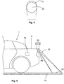
- FIG. 1 an assembly module 20 according to the invention and an authentication system 16 according to the invention have been used in a motor vehicle 1 according to the invention. Use in a rear region of the motor vehicle 1 with a tailgate 2 is shown here.
- An optical sensor system 30 of the assembly module 20 is in the area of the tailgate 2, z. B. in a handle strip of the tailgate 2, arranged.
- the optical sensor system 30 generates an actuation area 22 located outside of the motor vehicle 1.
- the optical sensor system 30 monitors the actuation area 22 after a successful authentication check.
- the optical sensor system 30 receives a signal from a Access control system 14 that an authorized user is authenticated.
- the access control system 14 had previously sent a wake-up signal to an ID transmitter 13 and the ID transmitter 13 had sent an authentication code to the access control system 14.
- the actuation region 22 having an inclined truncated cone, extends from a proximity to the optical sensor system 30 to a floor surface 15 on which the motor vehicle 1 stands. At the bottom surface 15, the actuation area 22 ends with an end surface 23.
- the actuation area 22 has an angle of inclination ⁇ to a plane 24 that is parallel to the bottom surface 15 and / or to a plane 17 that runs parallel to a plane connecting the vehicle axles.
- an object 18, in this case a foot 11 of a user 10 is located in the actuation area 22, the distance a of the object 18 to an optical sensor 50 of the optical sensor system 30 is detected.
- a light module 40 of the optical sensor system 30 emits pulsed infrared light. The light from the light module is reflected on the object 18 and received by the optical sensor 50.
- a light beam 47 which is reflected from a point on the object 18 or the end face 23 and received by a pixel 54 of the optical sensor 50 is shown.
- the optical sensor 50 is evaluated by a monitoring unit 60 of the optical sensor system 30. In order to determine the distance a, a time-of-flight measurement can be carried out.
- the optical sensor 50, the light module 40 and the monitoring unit 60 are shown in FIG Figure 10 shown.
- the monitoring unit 60 compares the detected distance a with a specification.
- the monitoring unit 60 only provides a work signal for opening the tailgate 2 if the specification is met. This creates a condition for the provision of the work signal, so that not every object 18 in the actuation area 22 triggers the work signal. Rather, there must be a will of the user who holds the object 18 in the actuation area 22 in such a way that the specification is met and the work signal is provided. The security for the user 10 is thus increased. It is provided here that the user 10 moves his foot 11 into the actuation area 22 in order to indicate his user will. When the tailgate 2 is opened, the tailgate 2 moves out of a door lock 8.
- the distance a can be compared directly with a minimum distance stored in the monitoring unit 60.
- the specification is only met if the distance a exceeds the minimum distance.
- the distance b between the end face 23 and the optical sensor 50 can first be detected as long as there is no object 18 in the actuation area 22.
- a ratio of the distance a to the distance b is formed and the value of this ratio is compared with a minimum value stored in the monitoring unit. Only if the value of the ratio of the distance a to the distance b exceeds the minimum value, the specification is met.
- the difference d between the distances a and b can be formed.
- the difference d denotes a distance from a surface 31 of the object 18 facing the optical sensor 50 to the end face 23.
- the specification is only met if the difference d falls below a maximum distance.
- the distance c which describes the distance between a surface facing the optical sensor and the end face 23, can be formed from the distances a and b and the angle of inclination ⁇ . The specification is met only when the distance c falls below a maximum value.
- a minimum distance condition is formulated by the above-mentioned specifications, through which the object must not come too close to the optical sensor. Thus, a user who comes too close to the motor vehicle 1 or a dog 19 in the actuation area 22 does not trigger the work signal.
- the minimum distance condition can be formulated in such a way that the user is in a puddle, as in Figure 4 shown, hold the foot over the end face 23 and still meet the minimum distance condition. So z. B. for the maximum distance of the distance c a value of 30 cm can be selected. Corresponding other minimum spacing conditions are conceivable according to the installation height E and / or the angle of inclination ⁇ .
- FIG. 5 the size of the end face 23 is shown in comparison to the foot 11.
- the end surface 23 has smaller spatial dimensions than the foot 11, so that a meaningful mean distance a between the foot 11 and the optical sensor 50 can easily be detected.
- a display element 43 of the mounting module 20 is shown.
- This display element 43 is also in the mounting module 20 of the Figures 1 to 4 available, but for the sake of clarity in the Figures 1 to 4 not shown.
- the display element 43 serves to make the end face 23 of the actuation area 22 visible to the user 10.
- the display element 43 emits visible light 46.
- the display element 43 is arranged close to the optical sensor system 30. This makes it possible for the area of the floor surface 15 illuminated by the display element 43 to be sufficiently congruent with the end area 23 even if the floor surface 15 is uneven.
- FIG. 7 a second assembly module 20 according to the invention is shown.
- the actuation area 22 ends here completely above the floor area 15. It is provided that the authorized user 10 reaches into the actuation area 22 with his hand 12 in such a way that the hand 12 fulfills the minimum distance condition and the work signal is provided.
- the first to third options for a minimum distance condition are conceivable here.
- the end face of the actuation area 22 is due to the decreasing intensity of the light emitted by the light module 40.
- the display element 43 does not make the end surface 23 of the actuation area 22 visible, but instead, by emitting visible light, indicates an actuation duration t B in which an object in the actuation area 22 that meets the minimum distance condition can trigger the work signal.
- FIG. 3 shows a third exemplary embodiment for a mounting module 20 according to the invention and an authentication system 16 according to the invention.
- the optical sensor system 30 of the mounting module 20 of Figure 8 is able to monitor a detection area 21.
- the detection area 21 is monitored from the time the motor vehicle 1 is parked until the authentication is successful.
- a user 10 can be recognized in the detection area 21 by the optical sensor system 30. If the user 10 is recognized, a signal is triggered to start an authentication check.
- the authentication check is carried out independently by the access control system 14 and the ID transmitter 13.
- the user 10 does not have to operate the ID transmitter 13, so that it is a passive entry check. If the authentication is successful, the optical sensor system 30 receives a signal that the user has been successfully authenticated. The optical sensor system 30 then monitors the actuation area 22.
- the detection area has the length L.
- the actuation area 22 is of smaller spatial dimensions than the detection area 21 and lies within the detection area 21.
- the actuation area 22 ends closer to the motor vehicle 1 than the detection area 21
- User 10 is first authenticated. The user 10 can then move the foot 11 into the actuation area 22.
- actuation area 22 is the only actuation area.
- a second actuation area 28 is also shown.
- an object 18 must meet the minimum distance condition in both actuation areas 22, 28 within a predefined actuation duration t B in order to provide the work signal.
- a second display element 45 of the assembly module 20 is used to make the second actuation area 28 visible.
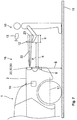
- FIG Figure 9 shows a fourth embodiment of how the assembly module 20 according to the invention and the authentication system 16 according to the invention are used.
- the mounting module 20 is in the Figure 9 arranged in a B-pillar 4 on one side of the vehicle.
- An approach to a side door 3 of the motor vehicle 1 is monitored by the detection area 21.
- the work signal can be used to open the side door 3.
- the actuation area 22 ends closer to the motor vehicle 1 than the detection area 21.
- the actuation area 22 lies outside the detection area 21.
- the actuation area 22 of the exemplary embodiment in FIG Figure 9 comprises the area of the door handle 5.
- a hand 12 of the user 10 which is located in the vicinity of the door handle 5, fulfills the minimum distance condition.
- the mounting module 20 has an installation plate 25 as a fastening element, an optical sensor system 30 and a display element 43.
- the optical sensor system 30 has a light module 40, which is shown in FIG Figure 10 is designed as a single light source 41.
- the light source 41 emits infrared light, as a result of which a transmission area 27 is created.
- the shape and shape of the transmission area 27 are achieved by a lens system 42 of the light source 41, which is only shown schematically.
- the optical sensor system 30 also has an optical sensor 50 which can receive light from a receiving area 26.
- the shape and shape of the receiving area 26 are predetermined by a schematically illustrated lens system 51 of the optical sensor 50.
- the detection area 21 shown with thick lines results from the superimposition of the transmission area 27 with the detection area 26.
- the optical sensor 50 has an infrared filter 52 in order to filter light of other wavelengths.
- the optical sensor also has an image sensor 53 on which the image is created.
- a monitoring unit 60 serves to evaluate the optical sensor 50.
- the optical sensor 50, the light module 40 and the monitoring unit 60 are fastened on the installation plate 25.
- the lens systems 42, 51 are rigid.
- the actuation area 22 lies within the detection area 21. This corresponds to the third exemplary embodiment.
- the detection area 21 and the actuation area 22 can be formed separately in the area of the superimposition of the transmission and reception area, so that the detection and actuation area 21, 22 as in FIG Figure 9 are arranged.
- the display element 43 is at a small distance f from the optical sensor 50.
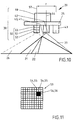
- Figure 11 shows a plan view of an image sensor 53 of a mounting module 20 according to the invention, which has a total number of pixels 54. Because the detection area 21 is also monitored with the same image sensor 53, only a few pixels 54, in particular between two and ten pixels 54, are used to map the actuation area 22 on the image sensor 53. Exemplary form in Figure 11 four pixels 54 from the actuation area 22. During the monitoring of the actuation area 22, only the pixels 56 assigned to the actuation area 22 are evaluated. The remaining pixels correspond to pixels 55 that have not been evaluated.
- Figure 12 contains a plot of a light intensity I over time ts.
- an image 61 is recorded with the aid of the image sensor 53 after each time span t, wherein in the Figure 12 a time interval t z is shown in each case, which is required for an image 61.
- This can be an identification image 64 or a comparison image 63.
- the identification image 64 has been recorded with the aid of light pulses 62 from the light module 40. A large number of light pulses 62 are necessary here in order to generate a recognition image 64.
- the light pulses 62 are emitted by the light module 40 with a predetermined pulse frequency.
- the light of the light pulses 62 of an image 61 received by the image sensor 53 is integrated or summed up in order to generate the recognition image 64.
- the optical sensor system 30 specifies the time interval tz in which the light pulses 62 generate an identification image 64.
- the distance between the user 10 and the optical sensor 50 is determined as a function of the intensity of the light pulses 62 in the time interval tz.
- An image 61 is recorded in the comparison image 63 without light pulses 62 from the light module 40 reaching the image sensor 53. To this end, the light module 40 does not emit any light.
- a method according to the invention is shown.
- the optical sensor system 30 monitors the detection area 21. If a user 10 is in the detection area 21 and the user 10 fulfills the specified criteria, the user 10 is recognized. In this case, a signal for the authentication check is triggered in a second step 72.
- the authentication check is carried out.
- the signal triggered in step 72 causes the access control system 14 to send a wake-up signal to the ID transmitter 13.
- the ID transmitter 13 then transmits an authentication code to the access control system 14.
- the access control system 14 compares the authentication code with a stored code. If the two codes match, the authentication is successful and an unlocking signal is triggered. This can be an unlocking signal for all doors of the motor vehicle 1 or just an unlocking signal for the tailgate 2 or the side door 3.
- a signal that the user 10 has been authenticated is received by the optical sensor system 30 in a fourth step 74.
- the actuation area 22 is started to be monitored. For this purpose, an actuation period is started.
- the display element 43 likewise begins to emit visible light in a first lighting state, so that the end surface 23 of the actuation region 22 is made visible to the user 10.
- the light module 40 emits pulsed infrared light in order to be able to carry out distance measurements.
- the optical sensor 50 receives the light from the light module 40, as a result of which an identification image 64 is produced.
- comparison images 63 are recorded and evaluated.
- the monitoring unit 60 evaluates the images 61 received.
- the distance b can be recorded and stored. If an object 18 is located in the actuation area 22, the distance a of the object 18 to the optical sensor 50 is detected in a step 76. At least one minimum distance condition is checked in a step 77 by the monitoring unit 60. So z. B. the distance a can be compared with the minimum distance stored in the monitoring unit and / or the difference between the distances b and a with a maximum distance. Only when the minimum distance condition is met, in a next step 78, the display element 43 is put into a second lighting state in which the light of the display element 43 periodically changes its brightness and thus flashes. At the same time, a distance duration t E started.
- the monitoring of the actuation area 22 is ended in a step 79 and the display element 43 is switched to a third lighting state in which the display element 43 provides a warning signal to the user 10. Thereafter, after a fixed predetermined time interval, the work signal for opening the tailgate 2 is provided in a step 80 and the display element 43 is switched off.
- Is in the operating time t B is no object 18 in the operating section 22 determines and / or is in operation time t B is the minimum distance condition is not met and / or in the removal period t E is not the object 18 from the operating portion 22 is removed, so is the end of the Actuation duration t B the monitoring of the actuation area 22 is set. This is indicated by the fact that the display element 43 no longer emits light.
- steps 71 to 73 and 78 to 79 are optional.
- the work signal can alternatively be provided directly after step 77.
- Step 74 corresponds to method step a
- steps 75 to 78 correspond to method step b
- step 77 to method step d and step 80 contains method step e.
Description
Die Erfindung betrifft ein Verfahren zum Bereitstellen eines Arbeitssignals für ein Kraftfahrzeug gemäß dem Patentanspruch 1. Des Weiteren betrifft die Erfindung ein Montagemodul für ein Kraftfahrzeug gemäß dem unabhängigen Patentanspruch 12.The invention relates to a method for providing a working signal for a motor vehicle according to
Die
Nachteilig hieran ist, dass der Benutzer das Öffnen der Fahrzeugtür auch einleitet, wenn der Benutzer sich vollständig in dem Bedienfeld befindet. Hierbei kann der Benutzer von der Fahrzeugtür getroffen und verletzt werden. Ebenso kann das Öffnen der Fahrzeugtür eingeleitet werden, wenn z. B. eine Katze oder ein Hund durch das Bedienfeld läuft und der Benutzer selber sich unmittelbar an der Fahrzeugtür befindet, so dass der Benutzer auch in diesem Fall von der Fahrzeugtür getroffen und verletzt werden kann.The disadvantage here is that the user also initiates the opening of the vehicle door when the user is completely in the control panel. The user can be hit and injured by the vehicle door. as well the opening of the vehicle door can be initiated if z. B. a cat or a dog runs through the control panel and the user himself is directly at the vehicle door, so that the user can be hit and injured by the vehicle door in this case too.
Es ist daher die Aufgabe der vorliegenden Erfindung, ein Verfahren und ein Montagemodul für ein Kraftfahrzeug bereitzustellen, das zumindest einen der vorgenannten Nachteile überwindet, insbesondere ein für den Benutzer gefahrloses Öffnen eines beweglichen Teils des Kraftfahrzeuges ermöglicht.It is therefore the object of the present invention to provide a method and an assembly module for a motor vehicle which overcomes at least one of the aforementioned disadvantages, in particular enables a movable part of the motor vehicle to be opened without risk for the user.
Zur Lösung der Aufgabe wird ein Verfahren mit sämtlichen Merkmalen des Anspruches 1 vorgeschlagen. Vorteilhafte Weiterbildungen des Verfahrens sind in den abhängigen Verfahrensansprüchen angegeben. Die Aufgabe wird weiterhin gelöst durch ein Montagemodul gemäß dem unabhängigen Anspruch 12. Vorteilhafte Weiterbildungen des Montagemoduls sind in den abhängigen Vorrichtungsansprüchen angegeben. Ferner wird ein Authentifizierungssystem mit einem erfindungsgemäßen Montagemodul, einem ID-Geber und einem Zugangskontrollsystem im Anspruch 23 unter Schutz gestellt. Merkmale und Details, die im Zusammenhang mit dem erfindungsgemäßen Montagemodul und/oder Authentifizierungssystem beschrieben sind, gelten dabei auch im Zusammenhang mit dem erfindungsgemäßen Verfahren und umgekehrt. Dabei können die in den Ansprüchen und in der Beschreibung erwähnten Merkmale jeweils einzeln für sich oder in Kombination erfindungswesentlich sein. Zusätzlich wird ein Kraftfahrzeug mit einem erfindungsgemäßen Montagemodul und/oder mit einem erfindungsgemäßen Authentifizierungssystem unter Schutz gestellt.To achieve the object, a method with all the features of
Erfindungsgemäß weist das Verfahren die folgenden Schritte auf:
- a) Erhalt eines Signals, dass ein berechtigter Benutzer authentifiziert ist,
- b) Überwachung eines außerhalb des Kraftfahrzeugs liegenden Betätigungsbereichs durch ein optisches Sensorsystem,
- c) Erfassung eines Abstandes eines Objektes im Betätigungsbereich zu einem optischen Sensor durch das optische Sensorsystem,
- d) Vergleich des Abstandes mit einer Vorgabe durch das optische Sensorsystem,
- e) Bereitstellen eines Arbeitssignals bei Erfüllung der Vorgabe.
- a) Receipt of a signal that an authorized user is authenticated,
- b) Monitoring of an operating area outside the motor vehicle by an optical sensor system,
- c) Detection of a distance between an object in the actuation area and an optical sensor by the optical sensor system,
- d) comparison of the distance with a specification by the optical sensor system,
- e) Providing a work signal when the specification is met.
Insbesondere wird Schritt b) nach Schritt a) ausgeführt. Die Schritte c) und d) werden insbesondere während Schritt b) ausgeführt. Bei Erfüllen der Vorgabe wird insbesondere Schritt b) beendet und Schritt e) ausgeführt. Der Vergleich kann ein direkter Vergleich, in dem der in Schritt c) erfasste Abstand direkt mit der Vorgabe verglichen wird, oder ein indirekter Vergleich, in dem durch den Abstand eine weitere Größe bestimmt wird und diese dann mit der Vorgabe verglichen wird, sein. Anders ausgedrückt, wird in Schritt d) der in Schritt c) erfasste Abstand zu einer Vorgabe in Beziehung gesetzt.In particular, step b) is carried out after step a). Steps c) and d) are carried out in particular during step b). If the specification is met, step b) is ended and step e) is carried out. The comparison can be a direct comparison in which the distance recorded in step c) is compared directly with the specification, or an indirect comparison in which a further variable is determined by the distance and this is then compared with the specification. In other words, in step d) the distance detected in step c) is related to a specification.
Dadurch, dass ein Abstand eines Objekts im Betätigungsbereich zu dem optischen Sensor erfasst wird, und dieser Abstand eine Vorgabe erfüllen muss, damit das Arbeitssignal bereitgestellt wird, wird eine Bedingung für das Bereitstellen des Arbeitssignals geschaffen, so dass nicht jedes Objekt im Betätigungsbereich das Arbeitssignal auslöst. Bei Abständen, die nicht die Vorgabe erfüllen, wird kein Arbeitssignal bereitgestellt. Vielmehr wird das Arbeitssignal nur bereitgestellt, wenn die Vorgabe erfüllt ist. Durch die Bedingung wird erreicht, dass eine Handlung des Benutzers im Betätigungsbereich, durch die nicht das Arbeitssignal ausgelöst werden soll, oder ein nicht erwünschtes Objekt, wie z. B. ein Hund, im Betätigungsbereich das Arbeitssignal nicht auslöst. Vielmehr wird nur durch eine bewusste Handlung des Benutzers das Arbeitssignal ausgelöst. Die bewusste Handlung des Benutzers kann insbesondere mit einer Hand oder einem Fuß durchgeführt werden. Dadurch, dass das Arbeitssignal nicht unerwünscht oder unerwartet bereitgestellt wird, wird der Benutzer davon nicht überrascht. Vielmehr wird ein Benutzerwillen erkannt. Somit gefährdet der durch das Arbeitssignal ausgelöste Vorgang, z. B. das Öffnen eines beweglichen Teils des Kraftfahrzeugs, den Benutzer weniger.The fact that a distance between an object in the actuation area and the optical sensor is detected, and this distance must meet a specification so that the work signal is provided, creates a condition for providing the work signal so that not every object in the actuation area triggers the work signal . No work signal is provided for distances that do not meet the specification. Rather, the work signal is only provided when the specification is met. The condition ensures that an action by the user in the operating area, by which the work signal is not to be triggered, or an undesired object, such as. B. a dog, does not trigger the work signal in the actuation area. Rather, the work signal is only triggered by a conscious action on the part of the user. The conscious action of the user can in particular be carried out with one hand or one foot. In that the working signal is not provided in an undesirable or unexpected manner, the user is not surprised by it. Rather, a user's will is recognized. Thus, the process triggered by the work signal, z. B. opening a moving part of the motor vehicle, the user less.
Das Arbeitssignal kann ein Signal zum Entriegeln und/oder Verriegeln und/oder Öffnen und/oder Schließen eines beweglichen Teils des Kraftfahrzeuges sein. Bei dem beweglichen Teil kann es sich insbesondere um eine Heckklappe und/oder eine Seitentür des Kraftfahrzeuges handeln. Die Heckklappe und/oder die Seitentür kann als Schiebetür ausgebildet sein. Durch das Arbeitssignal kann das bewegliche Teil z. B. entriegelt werden. Durch die Federwirkung einer Dichtung kann sich das bewegliche Teil danach teilweise aus einer geschlossenen Stellung bewegen und somit teilweise öffnen. Zusätzlich oder alternativ kann das Arbeitssignal ein Signal zur Aktivierung einer motorischen Öffnungs- und/oder Zuziehhilfe sein. Hierbei weist das Kraftfahrzeug einen Motor auf, der das bewegliche Teil vollständig öffnet und/oder schließt.The work signal can be a signal for unlocking and / or locking and / or opening and / or closing a movable part of the motor vehicle. The movable part can in particular be a tailgate and / or a side door of the motor vehicle. The tailgate and / or the side door can be designed as a sliding door. By the work signal, the moving part can, for. B. be unlocked. Due to the spring action of a seal, the movable part can then move partially out of a closed position and thus partially open. Additionally or alternatively the work signal can be a signal for activating a motorized opening and / or closing aid. Here, the motor vehicle has an engine that completely opens and / or closes the movable part.
Alternativ oder zusätzlich kann das Arbeitssignal ein Signal zum Ein- und/oder Ausfahren einer Anhängerkupplung sein. Insbesondere können bei der Überwachung des Betätigungsbereichs mehrere verschiedene Benutzerwillen, wie z. B. der Benutzerwille, ein bewegliches Teil zu öffnen, und der Benutzerwille, die Anhängerkupplung auszufahren, festgestellt werden.Alternatively or additionally, the work signal can be a signal for retracting and / or extending a trailer coupling. In particular, several different user wills, such as. B. the user's willingness to open a moving part, and the user's willingness to extend the trailer coupling can be determined.
Es ist denkbar, dass der Betätigungsbereich auf einer Bodenfläche, auf der das Kraftfahrzeug steht, endet. Der Betätigungsbereich weist an der Bodenfläche eine Endfläche auf. Hierbei kann der Betätigungsbereich im Wesentlichen orthogonal zur Bodenfläche verlaufen oder einen Neigungswinkel zu einer Ebene, die parallel zu einer die Fahrzeugachsen verbindenden Ebene verläuft, aufweisen. Dieser Neigungswinkel entspricht insbesondere dem Neigungswinkel des optischen Sensors.It is conceivable that the actuation area ends on a floor surface on which the motor vehicle is standing. The actuation area has an end surface on the bottom surface. Here, the actuation area can run essentially orthogonally to the floor surface or have an angle of inclination to a plane that runs parallel to a plane connecting the vehicle axles. This angle of inclination corresponds in particular to the angle of inclination of the optical sensor.
Insbesondere weist der Betätigungsbereich einen kegelstumpfförmigen Bereich mit einer runden oder elliptischen Grundfläche auf. Der kegelstumpfförmige Bereich kann insbesondere einem schrägen Kegelstumpf entsprechen.In particular, the actuation area has a frustoconical area with a round or elliptical base. The frustoconical area can in particular correspond to an inclined truncated cone.
Vorzugsweise entspricht die Vorgabe einer Mindestabstandsbedingung des Abstandes des Objekts zum optischen Sensor. Das Arbeitssignal wird somit nur dann bereitgestellt, wenn das Objekt dem optischen Sensor nicht zu nahe kommt. Hierdurch wird erreicht, dass der Benutzer weit genug vom optischen Sensor entfernt ist. Da der optische Sensor in der Nähe des beweglichen Teils eingebaut sein kann, kann hierdurch erreicht werden, dass der Benutzer sich weit genug entfernt von dem beweglichen Teil befindet. Somit kann die Sicherheit des Benutzers weiter erhöht werden.The specification preferably corresponds to a minimum distance condition for the distance between the object and the optical sensor. The work signal is thus only provided when the object does not come too close to the optical sensor. This ensures that the user is far enough away from the optical sensor. Since the optical sensor can be installed in the vicinity of the movable part, it can thereby be achieved that the user is located far enough away from the movable part. The safety of the user can thus be further increased.
Die Mindestabstandsbedingung kann als ein fester Wert in dem optischen Sensorsystem gespeichert sein. Alternativ kann die Mindestabstandsbedingung variabel gehalten sein. So kann die Mindestabstandsbedingung z. B. von einer Bodenfläche, auf der das Kraftfahrzeug steht, abhängig sein. Die Mindestabstandsbedingung kann in einer Überwachungseinheit des optischen Sensorsystems gespeichert sein.The minimum distance condition can be stored as a fixed value in the optical sensor system. Alternatively, the minimum distance condition can be kept variable. So the minimum distance condition z. B. from a floor surface on which the motor vehicle to be dependent. The minimum distance condition can be stored in a monitoring unit of the optical sensor system.
Insbesondere kann die Vorgabe, insbesondere die Mindestabstandsbedingung, einem fest vorgegebenen und in dem optischen Sensorsystem hinterlegten Mindestabstand des Objekts zum optischen Sensor entsprechen. Nur wenn der Abstand des Objekts zum optischen Sensor den Mindestabstand überschreitet, wird das Arbeitssignal bereitgestellt. In dem optischen Sensorsystem, insbesondere in der Überwachungseinheit, kann ein absoluter Wert für den Mindestabstand des Objekts zum optischen Sensor gespeichert sein. Während der Überwachung des Betätigungsbereichs wird der Abstand des Objekts zum optischen Sensor erfasst. Nur wenn der erfasste Abstand größer als der Mindestabstand ist, ist die Vorgabe erfüllt. Der Mindestabstand kann mit einer Einbauhöhe, mit der der optische Sensor in das Kraftfahrzeug einzubauen ist, variieren. Ebenfalls kann der Mindestabstand von dem Neigungswinkel des optischen Sensors variieren. So kann der Mindestabstand größer gewählt werden, je größer die Einbauhöhe und/oder je geringer der Neigungswinkel gewählt ist. Die Wahl eines festen Mindestabstands zum optischen Sensor hat den Vorteil, dass als Vorgabe ein direkter Grenzwert für die in Schritt c) erfasste Größe gewählt ist und somit die Rechenkapazität des optischen Sensorsystems geschont wird. Ebenfalls müssen keine weiteren Größen bei der Wahl des festen Mindestabstands als Vorgabe erfasst werden.In particular, the specification, in particular the minimum distance condition, can correspond to a fixedly predetermined minimum distance between the object and the optical sensor that is stored in the optical sensor system. The work signal is only provided if the distance between the object and the optical sensor exceeds the minimum distance. An absolute value for the minimum distance between the object and the optical sensor can be stored in the optical sensor system, in particular in the monitoring unit. During the monitoring of the actuation area, the distance between the object and the optical sensor is recorded. The requirement is only met if the recorded distance is greater than the minimum distance. The minimum distance can vary with an installation height at which the optical sensor is to be installed in the motor vehicle. The minimum distance from the angle of inclination of the optical sensor can also vary. The greater the installation height and / or the smaller the angle of inclination, the greater the minimum distance can be selected. Choosing a fixed minimum distance from the optical sensor has the advantage that a direct limit value for the variable detected in step c) is selected as the default and thus the computing capacity of the optical sensor system is spared. Likewise, when choosing the fixed minimum distance, no further parameters need to be entered as a specification.
Ebenfalls ist es denkbar, dass die Vorgabe, insbesondere die Mindestabstandsbedingung, einem Mindestwert für ein Verhältnis des Abstands des Objektes zum optischen Sensor zu einem Abstand einer Endfläche des Betätigungsbereichs zum optischen Sensor entspricht. Nur wenn durch einen entsprechenden Abstand des Objekts zum optischen Sensor der Mindestwert für das Verhältnis überschritten wird, wird das Arbeitssignal bereitgestellt. In dem optischen Sensorsystem, insbesondere in der Überwachungseinheit, kann ein absoluter Wert für den Mindestwert für das Verhältnis fest gespeichert sein. Der Abstand der Endfläche des Betätigungsbereichs zum optischen Sensor kann als fester Wert in dem optischen Sensorsystem hinterlegt oder vorzugsweise während der Überwachung vom optischen Sensorsystem erfasst werden. Während der Überwachung des Betätigungsbereichs wird der Abstand des Objekts zum optischen Sensor erfasst. Das Verhältnis des Abstands des Objekts zum optischen Sensor zum Abstand der Endfläche des Betätigungsbereichs zum optischen Sensor wird gebildet. Nur wenn das Verhältnis größer als der Mindestwert ist, ist die Vorgabe erfüllt. Der Mindestwert kann mit der Einbauhöhe und dem Neigungswinkel des optischen Sensors variieren. Insbesondere kann mit zunehmender Einbauhöhe und abnehmendem Neigungswinkel der Mindestwert erhöht sein.It is also conceivable that the specification, in particular the minimum distance condition, corresponds to a minimum value for a ratio of the distance between the object and the optical sensor to a distance between an end surface of the actuation area and the optical sensor. The work signal is only provided if the minimum value for the ratio is exceeded due to a corresponding distance between the object and the optical sensor. An absolute value for the minimum value for the ratio can be permanently stored in the optical sensor system, in particular in the monitoring unit. The distance between the end face of the actuation area and the optical sensor can be stored as a fixed value in the optical sensor system or, preferably, can be detected by the optical sensor system during monitoring. During the monitoring of the actuation area, the distance between the object and the optical sensor is recorded. The ratio of the distance between the object and the optical sensor to the distance between the end face of the actuation area and the optical sensor is formed. Only when the ratio is greater than the minimum value, the requirement is met. The minimum value can vary with the installation height and the angle of inclination of the optical sensor. In particular, the minimum value can be increased with increasing installation height and decreasing angle of inclination.
Wird der Mindestwert als Vorgabe gewählt, so kann vorteilhafterweise ein sich ändernder Betätigungsbereich bei der Vorgabe berücksichtigt werden. Endet der Betätigungsbereich auf der Bodenfläche, so kann die Vorgabe dem Mindestwert für ein Verhältnis des Abstands des Objektes zum optischen Sensor zu einem Abstand der Bodenfläche im Betätigungsbereich zum optischen Sensor entsprechen. Ist die Bodenfläche hügelig, so kann hierdurch die hügelige Bodenfläche bei der Erfüllung der Vorgabe berücksichtigt werden.If the minimum value is selected as a default, a changing operating range can advantageously be taken into account in the default. If the actuation area ends on the floor surface, the specification can correspond to the minimum value for a ratio of the distance between the object and the optical sensor to a distance between the floor surface in the actuation area and the optical sensor. If the floor area is hilly, the hilly floor area can be taken into account when fulfilling the requirement.
Als eine weitere Möglichkeit kann vorgesehen sein, dass die Vorgabe, insbesondere die Mindestabstandsbedingung, einer fest vorgegebenen und in dem optischen Sensorsystem hinterlegten maximalen Entfernung einer dem optischen Sensor zugewandten Oberfläche des Objektes zu einer Endfläche des Betätigungsbereichs, die sich insbesondere an einer Bodenfläche befindet, entspricht. Nur wenn die Entfernung der dem optischen Sensor zugewandten Oberfläche des Objekts zu einer Endfläche des Betätigungsbereichs, insbesondere an der Bodenfläche, die maximale Entfernung unterschreitet, wird das Arbeitssignal bereitgestellt. In dem optischen Sensorsystem, insbesondere in der Überwachungseinheit, kann ein absoluter Wert für die maximale Entfernung gespeichert sein. Der Abstand der Endfläche des Betätigungsbereichs zum optischen Sensor kann als fester Wert in dem optischen Sensorsystem hinterlegt oder vorzugsweise während der Überwachung vom optischen Sensorsystem erfasst werden. Während der Überwachung des Betätigungsbereichs wird der Abstand des Objekts zum optischen Sensor erfasst. Aus dem Abstand der Endfläche des Betätigungsbereichs zum optischen Sensor und dem Abstand des Objekts zum optischen Sensor wird die Entfernung einer dem optischen Sensor zugewandten Oberfläche des Objekts zur Endfläche des Betätigungsbereichs, insbesondere zur Bodenfläche, bestimmt. Nur wenn die so bestimmte Entfernung kleiner als die maximale Entfernung ist, ist die Vorgabe erfüllt. Hierdurch wird eine weitere Möglichkeit geschaffen, eine variierende Länge des Betätigungsbereichs, insbesondere bei einer variierenden Bodenfläche, zu berücksichtigen.As a further possibility, it can be provided that the specification, in particular the minimum distance condition, corresponds to a fixed maximum distance stored in the optical sensor system from a surface of the object facing the optical sensor to an end surface of the actuation area, which is located in particular on a floor surface . The work signal is provided only when the distance between the surface of the object facing the optical sensor and an end surface of the actuation area, in particular on the floor surface, falls below the maximum distance. An absolute value for the maximum distance can be stored in the optical sensor system, in particular in the monitoring unit. The distance between the end face of the actuation area and the optical sensor can be stored as a fixed value in the optical sensor system or, preferably, can be detected by the optical sensor system during monitoring. During the monitoring of the actuation area, the distance between the object and the optical sensor is recorded. The distance from a surface of the object facing the optical sensor to the end surface of the actuation area, in particular to the floor surface, is determined from the distance between the end face of the actuation area and the optical sensor and the distance between the object and the optical sensor. The specification is only met if the distance determined in this way is smaller than the maximum distance. This creates a further possibility of taking into account a varying length of the actuation area, in particular in the case of a varying floor area.
Über einen Auftreffwinkel auf der Bodenfläche und die Abstände des Objekts und der Endfläche zum optischen Sensor kann ein zur Bodenfläche orthogonaler Abstand c der dem optischen Sensor zugewandten Oberfläche des Objekts zur Endfläche ermittelt werden. Es ist denkbar, dass nur wenn der Abstand c einen maximalen Abstand unterschreitet, das Arbeitssignal bereitgestellt wird. Der maximale Abstand kann in dem optischen Sensorsystem fest vorgegeben sein. Der Auftreffwinkel entspricht bei einer ebenen Bodenfläche dem Neigungswinkel. Es ist denkbar, vereinfachend den Neigungswinkel anstelle des Auftreffwinkels zu verwenden.An angle of incidence on the floor surface and the distances between the object and the end surface and the optical sensor can be used to determine a distance c, orthogonal to the floor surface, of the surface of the object facing the optical sensor and the end surface. It is conceivable that the work signal is provided only when the distance c falls below a maximum distance. The maximum distance can be fixed in the optical sensor system. The angle of incidence corresponds to the angle of inclination in the case of a flat floor surface. It is conceivable to use the angle of inclination instead of the angle of incidence to simplify matters.
Insbesondere, wenn der Betätigungsbereich an der Bodenfläche endet, kann die Mindestabstandsbedingung so ausgelegt sein, dass der Abstand c einem maximalen Abstand entsprechen darf, um die Vorgabe zu erfüllen. Im Regelfall kann vorgesehen sein, dass der Benutzer mit dem Fuß auf die Bodenfläche im Betätigungsbereich treten muss, um die Vorgabe zu erfüllen. Um den Falle einer Pfütze oder einer sumpfigen Stelle an der Bodenfläche des Betätigungsbereichs zu berücksichtigen, kann jedoch auch vorgesehen sein, dass der Benutzer den Fuß geringfügig oberhalb der Bodenfläche halten darf, um die Vorgabe zu erfüllen. So kann insbesondere der maximale Abstand cmax für den Abstand c mit 0 ≤ cmax ≤ 30 cm, bevorzugt 0 ≤ cmax ≤ 20 cm, besonders bevorzugt 0 ≤ cmax ≤ 10 cm gewählt sein. Auch wenn eine andere Mindestabstandsbedingung gewählt wird, kann diese so vorgegeben werden, dass die genannten Bedingungen für cmax zutreffen.In particular, if the actuation area ends at the floor surface, the minimum distance condition can be designed such that the distance c may correspond to a maximum distance in order to meet the requirement. As a rule, it can be provided that the user has to step with his foot on the floor surface in the actuation area in order to meet the requirement. In order to take into account the case of a puddle or a swampy spot on the floor surface of the actuation area, however, provision can also be made for the user to be allowed to hold the foot slightly above the floor surface in order to meet the requirement. In particular, the maximum distance c max for the distance c can be selected as 0 c max 30 cm, preferably 0 c max 20 cm, particularly preferably 0 c max 10 cm. Even if a different minimum distance condition is selected, it can be specified so that the stated conditions apply to c max .
Die verschiedenen Möglichkeiten für eine Mindestabstandsbedingung können beliebig kombiniert werden. So können ein fest vorgegebener Mindestabstand, ein Mindestwert für das Verhältnis, eine fest vorgegebene maximale Entfernung und/oder ein fest vorgegebener maximaler Abstand vorgesehen sein.The various options for a minimum distance condition can be combined as desired. A fixed predetermined minimum distance, a minimum value for the ratio, a fixed predetermined maximum distance and / or a fixed predetermined maximum distance can thus be provided.
Bei den erfassten Abständen kann es sich insbesondere um über das ganze Objekt und/oder über die ganze Endfläche gemittelte Abstände handeln. Alternativ kann es sich um einzelne Punkte des Objekts und/oder der Endfläche handeln. Insbesondere können z. B. der Abstand des Objekts zum optischen Sensor und der Abstand der Endfläche zum optischen Sensor, die auf einer Geraden liegen, miteinander in Beziehung gesetzt werden.The detected distances can in particular be distances averaged over the entire object and / or over the entire end surface. Alternatively, they can be individual points of the object and / or the end face. In particular, z. B. the distance of the object to the optical sensor and the distance of the end face to the optical sensor, which lie on a straight line, can be related to each other.
Das optische Sensorsystem kann insbesondere anhand einer Intensitätsänderung des empfangenen Lichts bestimmen, dass sich ein Objekt in dem Betätigungsbereich befindet.The optical sensor system can determine, in particular on the basis of a change in the intensity of the received light, that an object is located in the actuation area.
Um einen Abstand des Objektes zum optischen Sensor erfassen zu können, kann beispielsweise eine Time of Flight Messung durchgeführt werden. Hierbei werden z. B. ein oder mehrere Lichtpulse von dem optischen Sensorsystem, insbesondere von einem Lichtmodul des optischen Sensorsystems, emittiert und die Zeit, die der Lichtpuls zum Objekt und von dort zum optischen Sensor benötigt, gemessen. Die Zeit ist hierbei direkt proportional zum Abstand des Objektes. Es kann sein, dass mehrere Lichtpulse nacheinander von dem optischen Sensorsystem, insbesondere von dem Lichtmodul, emittiert werden, um ein Bild erzeugen zu können. Die Lichtpulse können aufintegriert oder aufsummiert werden, um das Bild zu erzeugen. Um in diesem Fall eine Abstandserfassung durchführen zu können, wird ein bestimmtes Zeitintervall für die Bildaufnahme in dem optischen Sensorsystem vorgegeben. Die gesamte Intensität der in dem optischen Sensor empfangenen Lichtpulse in dem Zeitintervall wird mit dem Abstand korreliert.In order to be able to detect a distance between the object and the optical sensor, a time of flight measurement can be carried out, for example. Here z. B. emitted one or more light pulses from the optical sensor system, in particular from a light module of the optical sensor system, and measured the time it takes for the light pulse to reach the object and from there to the optical sensor. The time is directly proportional to the distance to the object. It can be the case that several light pulses are emitted one after the other by the optical sensor system, in particular by the light module, in order to be able to generate an image. The light pulses can be integrated or summed up in order to generate the image. In order to be able to carry out a distance detection in this case, a specific time interval is specified for the image recording in the optical sensor system. The total intensity of the light pulses received in the optical sensor in the time interval is correlated with the distance.
Um die Messgenauigkeit zu erhöhen, kann vorgesehen sein, dass ein Bild, das nur mit dem Licht, das vom optischen Sensorsystem, insbesondere von dem Lichtmodul, emittiert wurde, generiert wird. So kann es sein, dass Erkennungsbilder und Vergleichsbilder aufgenommen und gegebenenfalls ausgewertet werden. Erkennungsbilder entstehen mit Hilfe der Reflexion des emittierten Lichts des Lichtmoduls. Vergleichsbilder entstehen nur mit Hilfe von Störlicht. Bei dem Störlicht kann es sich beispielsweise um Sonnenlicht oder um Licht einer künstlichen Lichtquelle, z. B. Garagenlicht, handeln. Zum Entstehen der Vergleichsbilder emittiert das Lichtmodul kein Licht. Die Überwachungseinheit kann durch Vergleich eines Erkennungsbildes und eines Vergleichsbildes das Störlicht erkennen. Das optische Sensorsystem, insbesondere die Überwachungseinheit, kann hierdurch ein modifiziertes Erkennungsbild generieren, aus dem das Störlicht entfernt ist. Es kann vorgesehen sein, dass jeweils nach einer vorgegebenen Anzahl von Erkennungsbildern ein Vergleichsbild aufgenommen wird.In order to increase the measurement accuracy, it can be provided that an image that is generated only with the light that was emitted by the optical sensor system, in particular by the light module. It can be the case that identification images and comparison images are recorded and, if necessary, evaluated. Identification images are created with the help of the reflection of the light emitted by the light module. Comparison images are only created with the help of interfering light. The stray light can be, for example, sunlight or light from an artificial light source, e.g. B. garage light act. The light module does not emit any light in order to generate the comparison images. The monitoring unit can recognize the interfering light by comparing a recognition image and a comparison image. The optical sensor system, in particular the monitoring unit, can thereby generate a modified detection image from which the interfering light has been removed. Provision can be made for a comparison image to be recorded after a predetermined number of identification images.
Es kann sein, dass weitere Maßnahmen getroffen werden, damit der Benutzer das Kraftfahrzeug gefahrlos öffnen kann.It may be that further measures are taken so that the user can safely open the motor vehicle.
So ist es denkbar, dass der Betätigungsbereich nur eine vorgegebene Betätigungsdauer tB lang überwacht wird. Eine maximale Länge der Betätigungsdauer tB kann fest vorgegeben und in dem optischen Sensorsystem gespeichert sein. Abstände von Objekten, die sich außerhalb der Betätigungsdauer tB im Betätigungsbereich aufhalten, werden nicht erfasst. Somit kann außerhalb der Betätigungsdauer tB kein Arbeitssignal ausgelöst werden. Durch die Betätigungsdauer kann nur in einem beschränkten Zeitraum ein Arbeitssignal ausgelöst werden, so dass die Gefahr von Fehlauslösungen verringert wird. Die Betätigungsdauer tB kann insbesondere gering gewählt sein. So kann tB mit 3 s ≤ tB ≤ 30 s, bevorzugt 5 s ≤ tB ≤ 15 s gewählt sein. Die Betätigungsdauer tB kann insbesondere durch den Erhalt des Signals, dass ein berechtigter Benutzer authentifiziert ist, gestartet werden und/oder direkt nach dem Erhalt dieses Signals beginnen. Die Betätigungsdauer kann nach Ablauf der maximalen Länge oder vorzeitig, z. B. mit dem Bereitstellen des Arbeitssignals oder mit dem Erfüllen der dafür nötigen Vorgabe(n), enden. Es kann vorgesehen sein, dass der Anfang und das Ende der Betätigungsdauer tB für den Benutzer wahrnehmbar sind.It is thus conceivable that the actuation area is only monitored for a predefined actuation duration t B. A maximum length of the actuation duration t B can be predetermined and stored in the optical sensor system. Distances from objects that are outside the actuation period t B in the actuation area are not recorded. This means that no work signal can be triggered outside of the actuation period t B. Due to the duration of the actuation, a work signal can only be triggered for a limited period of time, so that the risk of false triggering is reduced. The actuation duration t B can in particular be selected to be short. Thus, t B can be chosen with 3 s t B 30 s, preferably 5 s t B 15 s. The actuation duration t B can be started in particular by receiving the signal that an authorized user is authenticated and / or can begin immediately after receiving this signal. The duration of the operation can after the maximum length or prematurely, z. B. with the provision of the work signal or with the fulfillment of the required specification (s), end. It can be provided that the beginning and the end of the actuation period t B can be perceived by the user.
Vorzugsweise kann nur bei Erfüllung mindestens einer weiteren Vorgabe das Arbeitssignal bereitgestellt werden. Hierdurch wird ebenfalls die Sicherheit für den Benutzer erhöht.The work signal can preferably only be provided when at least one further specification is fulfilled. This also increases the safety for the user.
So kann während der Überwachung zusätzlich zu Schritt b) die Größe des Objekts bestimmt werden. Nur wenn die Größe eine Mindestgröße überschreitet und/oder eine maximale Größe unterschreitet, kann das Arbeitssignal bereitgestellt werden.Thus, in addition to step b), the size of the object can be determined during the monitoring. The work signal can only be provided if the size exceeds a minimum size and / or falls below a maximum size.
Alternativ oder zusätzlich kann ein definierter Bewegungsablauf des Objekts im Betätigungsbereich vorgegeben sein. Nur wenn der definierte Bewegungsablauf erfolgt, wird das Arbeitssignal bereitgestellt. Bei dem definierten Bewegungsablauf kann es sich z. B. um eine vorgegebene Gestik handeln. Es kann sein, dass mehrere Messungen des Abstands des Objekts zum optischen Sensor durchgeführt werden, um den Bewegungsablauf im Betätigungsbereich erkennen zu können. Hierbei wird insbesondere der Abstand bei zumindest zwei aufeinanderfolgenden Bildern, insbesondere Erkennungsbildern, erfasst. Der Abstand kann durch eine Time of Flight Messung erfasst werden.Alternatively or additionally, a defined movement sequence of the object can be specified in the actuation area. The work signal is only provided when the defined sequence of movements takes place. In the defined sequence of movements it can be, for. B. act to a predetermined gesture. It may be that several measurements of the distance of the object to the optical sensor are carried out in order to be able to recognize the movement sequence in the actuation area. In this case, in particular, the distance is detected in at least two successive images, in particular recognition images. The distance can be recorded by a time of flight measurement.
Denkbar ist, dass während der Überwachung die Aufenthaltsdauer des Objekts im Betätigungsbereich erfasst wird. Nur wenn die Aufenthaltsdauer eine Mindestaufenthaltsdauer überschreitet und/oder eine maximale Aufenthaltsdauer unterschreitet, kann das Arbeitssignal bereitgestellt werden.It is conceivable that the length of stay of the object in the actuation area is recorded during the monitoring. Only if the length of stay is a If the minimum duration of stay exceeds and / or falls below a maximum duration of stay, the work signal can be provided.
Ebenfalls ist es möglich, dass ein Entfernen des Objekts innerhalb einer vorgegebenen Entfernungsdauer tE aus dem Betätigungsbereich erfolgen muss, damit das Arbeitssignal bereitgestellt wird. So kann es vorgesehen sein, dass, wenn als Resultat des Schritts d) die Vorgabe erfüllt ist, die Entfernungsdauer tE beginnt. Der Beginn der Entfernungsdauer tE ist für den Benutzer wahrnehmbar. Nur wenn das Objekt, insbesondere ein Körperteil des Benutzers, innerhalb der Entfernungsdauer tE aus dem Betätigungsbereich entfernt wird, wird das Arbeitssignal bereitgestellt.It is also possible that the object must be removed from the actuation area within a predetermined distance t E so that the work signal is provided. It can thus be provided that, if the stipulation is met as a result of step d), the distance duration t E begins. The beginning of the distance duration t E can be perceived by the user. The work signal is only provided if the object, in particular a part of the body of the user, is removed from the actuation area within the distance period t E.
Ebenfalls ist es denkbar, dass ein zweiter Betätigungsbereich vorhanden ist. Der zweite Betätigungsbereich kann ebenfalls durch das optische Sensorsystem überwacht werden. So ist es denkbar, dass ein Objekt sich im zweiten Betätigungsbereich aufhalten muss, insbesondere in dem zweiten Betätigungsbereich eine der bereits genannten Vorgaben erfüllt sein muss, damit das Arbeitssignal bereitgestellt wird.
Zusätzlich oder alternativ kann eine Mindestentfernung und/oder eine bestimmte Position des berechtigten Benutzers vom optischen Sensor und/oder vom Kraftfahrzeug notwendig sein, damit das Arbeitssignal bereitgestellt wird. Bezüglich der Position kann z. B. festgestellt werden, ob sich der Benutzer vor, neben oder hinter dem Kraftfahrzeug befindet. Die Mindestentfernung und/oder die Position kann zu jeder Zeit während oder nach der Authentifizierung bestimmt werden. Insbesondere kann die Mindestentfernung und/oder die Position auch nach Ende der Betätigungsdauer bestimmt werden. Die Entfernung des berechtigten Benutzers vom Kraftfahrzeug und/oder vom optischen Sensor und/oder die Position des berechtigten Benutzers wird erfasst. Hierbei kann die Entfernung des Benutzers vom Kraftfahrzeug und/oder eine Position des Benutzers, z. B. anhand der Stärke eines von einem ID-Geber ausgesendeten Signals, ermittelt werden. Beispielsweise kann der Receive Signal Strength Indicator (RSSI) hierzu verwendet werden. Durch die Ermittlung der Stärke des ausgesendeten Signals kann sichergestellt werden, dass nur der berechtigte Benutzer selber in den Detektionsbereich gelangt ist und seinen Benutzerwillen im Betätigungsbereich kundgetan hat. Es ist denkbar, den RSSI zyklisch abzufragen. Alternativ kann die Entfernung des Benutzers vom optischen Sensor durch das optische Sensorsystem ermittelt werden. Hierbei kann ein Detektionsbereich, der weiter entfernt als der Betätigungsbereich vom Kraftfahrzeug endet, von dem optischen Sensorsystem überwacht werden und die Entfernung des Benutzers zum optischen Sensor im Detektionsbereich erfasst werden. Nur wenn der Benutzer die Mindestentfernung vom Kraftfahrzeug und/oder vom optischen Sensor entfernt ist und/oder in einer vorgegebenen Position am Kraftfahrzeug steht, wird das Arbeitssignal ausgelöst.It is also conceivable that a second actuation area is present. The second actuation area can also be monitored by the optical sensor system. It is conceivable that an object has to be in the second actuation area, in particular one of the previously mentioned requirements must be met in the second actuation area so that the work signal is provided.
Additionally or alternatively, a minimum distance and / or a specific position of the authorized user from the optical sensor and / or from the motor vehicle may be necessary so that the work signal is provided. Regarding the position, for. B. can be determined whether the user is in front of, next to or behind the motor vehicle. The minimum distance and / or the position can be determined at any time during or after the authentication. In particular, the minimum distance and / or the position can also be determined after the end of the actuation period. The distance of the authorized user from the motor vehicle and / or from the optical sensor and / or the position of the authorized user is recorded. Here, the distance of the user from the motor vehicle and / or a position of the user, e.g. B. based on the strength of a signal sent by an ID transmitter can be determined. For example, the Receive Signal Strength Indicator (RSSI) can be used for this. By determining the strength of the transmitted signal, it can be ensured that only the authorized user himself has entered the detection area and has made known his / her intention to use in the actuation area. It is conceivable to poll the RSSI cyclically. Alternatively, the distance of the user from the optical sensor can be determined by the optical sensor system. Here, a detection area that is further away than the actuation area from Motor vehicle ends, are monitored by the optical sensor system and the distance of the user to the optical sensor in the detection area can be detected. The work signal is triggered only when the user is the minimum distance from the motor vehicle and / or from the optical sensor and / or is in a predetermined position on the motor vehicle.
Eine weitere Möglichkeit, die Sicherheit des Benutzers zu erhöhen, kann durch ein Warnsignal erreicht werden. So kann vor dem Auslösen des Arbeitssignals ein für den Benutzer wahrnehmbares Warnsignal abgegeben werden.Another possibility to increase the safety of the user can be achieved by means of a warning signal. In this way, a warning signal that can be perceived by the user can be emitted before the work signal is triggered.
Können bei der Überwachung des Betätigungsbereichs verschiedene Benutzerwillen festgestellt werden, so können verschiedenen Bewegungsabläufen verschiedene Benutzerwillen zugeordnet werden. So kann z. B. mit dem Fuß in den Betätigungsbereich treten ein Öffnen der Heckklappe verursachen, während eine seitliche Bewegung einer Hand nahe dem optischen Sensor ein Ausfahren der Anhängerkupplung bewirkt.If different user wills can be determined when monitoring the operating area, different user wills can be assigned to different movement sequences. So z. B. step with the foot in the operating area cause the tailgate to open, while a lateral movement of a hand near the optical sensor causes the trailer hitch to extend.
Es ist denkbar, dass vor dem Schritt a) weitere Schritte ausgeführt werden. So kann zunächst ein außerhalb des Kraftfahrzeugs liegender Detektionsbereich durch das optische Sensorsystem überwacht werden und im Falle eines Erkennens des Benutzers im Detektionsbereich ein Signal für den Start einer Authentifizierungsüberprüfung zwischen einem ID-Geber und einem Zugangskontrollsystem des Kraftfahrzeuges ausgelöst werden. Danach kann eine Authentifizierungsüberprüfung durch das Authentifizierungssystem stattfinden. An diese Schritte können sich die Verfahrensschritte a) bis e) anschließen. Der Detektionsbereich wird insbesondere überwacht, um die Nähe eines Benutzers feststellen zu können. Durch die Überwachung des Detektionsbereichs und die Auslösung eines Startsignals für die Authentifizierungsüberprüfung kann insbesondere eine Passive-Keyless-Entry-Überprüfung eingeleitet werden. Hierbei muss der Benutzer nicht den ID-Geber betätigen, um die Authentifizierungsüberprüfung auszulösen. Die zusätzlichen Verfahrensschritte haben den Vorteil, dass mit demselben optischen Sensorsystem bzw. Authentifizierungssystem sowohl die Authentifizierungsüberprüfung eingeleitet bzw. durchgeführt werden kann, die auch die Verfahrensschritte a) bis e) durchführen. Das Erkennen eines Benutzers im Detektionsbereich kann an das Erfüllen bestimmter Kriterien wie Größe, Aufenthaltsdauer, Bewegung und/oder Bewegungsrichtung des Benutzers geknüpft sein.It is conceivable that further steps are carried out before step a). A detection area outside the motor vehicle can first be monitored by the optical sensor system and, if the user is recognized in the detection area, a signal for starting an authentication check between an ID transmitter and an access control system of the motor vehicle can be triggered. An authentication check can then take place by the authentication system. Process steps a) to e) can follow these steps. The detection area is monitored in particular in order to be able to determine the proximity of a user. By monitoring the detection area and triggering a start signal for the authentication check, in particular a passive keyless entry check can be initiated. The user does not have to press the ID transmitter to trigger the authentication check. The additional method steps have the advantage that both the authentication check can be initiated or carried out with the same optical sensor system or authentication system, which also carry out method steps a) to e). The recognition of a user in the detection area can indicate the fulfillment of certain criteria such as size, length of stay, movement and / or direction of movement of the user.
Die Aufgabe der Erfindung wird auch gelöst durch ein Montagemodul für ein Kraftfahrzeug, mit einem optischen Sensorsystem, das geeignet ist,
- a) ein Signal, dass ein berechtigter Benutzer authentifiziert ist, zu erhalten,
- b) einen außerhalb des Kraftfahrzeuges liegenden Betätigungsbereich zu überwachen,
- c) einen Abstand eines Objektes im Betätigungsbereich zu einem optischen Sensor des Sensorsystems zu erfassen,
- d) den Abstand mit einer Vorgabe zu vergleichen,
- e) ein Arbeitssignal bei Erfüllen der Vorgabe bereitzustellen.
- a) to receive a signal that an authorized user is authenticated,
- b) to monitor an operating area outside the vehicle,
- c) to detect a distance of an object in the actuation area to an optical sensor of the sensor system,
- d) to compare the distance with a specification,
- e) provide a work signal when the target is met.
Ebenfalls wird die Aufgabe durch ein erfindungsgemäßes Authentifizierungssystem mit einem erfindungsgemäßen Montagemodul, einem ID-Geber und einem Zugangskontrollsystem gelöst. Insbesondere ist das Montagemodul und/oder das Authentifizierungssystem geeignet, ein erfindungsgemäßes Verfahren auszuführen. Hierzu kann insbesondere das optische Sensorsystem eine Überwachungseinheit mit einem Prozessor und einem Speicher aufweisen, mit dessen Hilfe das erfindungsgemäße Verfahren ausführbar ist. Das erfindungsgemäße Verfahren kann in dem Speicher hinterlegt sein. Die optische Überwachungseinheit kann ferner dazu ausgebildet sein, Bilder auszuwerten, die vom optischen Sensor aufgenommen worden sind.The object is also achieved by an authentication system according to the invention with a mounting module according to the invention, an ID transmitter and an access control system. In particular, the assembly module and / or the authentication system is suitable for carrying out a method according to the invention. For this purpose, the optical sensor system in particular can have a monitoring unit with a processor and a memory, with the aid of which the method according to the invention can be carried out. The method according to the invention can be stored in the memory. The optical monitoring unit can also be designed to evaluate images that have been recorded by the optical sensor.
Ferner kann das optische Sensorsystem den optischen Sensor aufweisen, um Licht aus dem Betätigungsbereich zu empfangen. Der optische Sensor nimmt Bilder des Betätigungsbereichs auf. Hierzu kann der optische Sensor ein Linsensystem und/oder einen Bildsensor aufweisen. Der Bildsensor kann ein CMOS-Sensor und/oder ein LDPD-Sensor sein. Der LDPD-Sensor (Lateral Drift Field Photodetector) ist in der Druckschrift
Das optische Sensorsystem kann ein Lichtmodul zum Emittieren von Licht aufweisen. Das Licht dient dazu, den Betätigungsbereich entstehen zu lassen. Hierzu kann das Lichtmodul ein Linsensystem aufweisen. Es kann vorgesehen sein, dass das Lichtmodul Licht im nicht sichtbaren Bereich emittiert. Insbesondere kann es sich bei dem Licht um Infrarotstrahlen, insbesondere um nahe Infrarotstrahlen, handeln. Das Lichtmodul kann nur eine Lichtquelle aufweisen. Alternativ kann das Lichtmodul mehrere Lichtquellen aufweisen. Die Lichtquellen können um den optischen Sensor angeordnet sein. So können z. B. Lichtquellen links und rechts von dem optischen Sensor angeordnet sein. Alternativ können die Lichtquellen um den Umfang des optischen Sensors herum angeordnet sein. Bei dem Licht kann es sich um Laserlicht handeln. Das vom Lichtmodul emittierte Licht kann gepulst sein.The optical sensor system can have a light module for emitting light. The light is used to create the actuation area. The light module have a lens system. It can be provided that the light module emits light in the non-visible range. In particular, the light can be infrared rays, in particular near infrared rays. The light module can have only one light source. Alternatively, the light module can have several light sources. The light sources can be arranged around the optical sensor. So z. B. light sources can be arranged to the left and right of the optical sensor. Alternatively, the light sources can be arranged around the circumference of the optical sensor. The light can be laser light. The light emitted by the light module can be pulsed.
Es kann vorgesehen sein, dass der optische Sensor einen Infrarotfilter und/oder einen Polarisationsfilter aufweist. Hierdurch kann zumindest ein Teil eines Störlichtes herausgefiltert werden. Ebenfalls kann das Lichtmodul einen Polarisationsfilter aufweisen.It can be provided that the optical sensor has an infrared filter and / or a polarization filter. In this way, at least part of an interfering light can be filtered out. The light module can also have a polarization filter.
Das Montagemodul kann ein Befestigungselement, insbesondere eine Installationsplatte, aufweisen, um einzelne Elemente des optischen Sensorsystems, d. h. den optischen Sensor, das Lichtmodul und/oder die Überwachungseinheit zu befestigen. Alternativ oder zusätzlich kann das Montagemodul ein Gehäuse umfassen, das das optische Sensorsystem zumindest teilweise umgibt. Die Überwachungseinheit kann zusammen mit dem Zugangskontrollsystem ausgebildet sein. Insbesondere bei einem Lichtmodul mit mehreren Lichtquellen kann das Befestigungselement kugelabschnittsartig ausgebildet sein.The mounting module can have a fastening element, in particular an installation plate, in order to secure individual elements of the optical sensor system, d. H. to attach the optical sensor, the light module and / or the monitoring unit. Alternatively or additionally, the assembly module can comprise a housing which at least partially surrounds the optical sensor system. The monitoring unit can be designed together with the access control system. In particular in the case of a light module with a plurality of light sources, the fastening element can be configured in the manner of a segment of a sphere.
Es kann vorgesehen sein, dass optische Sensorsystem oder das gesamte Montagemodul zur Anordnung am Fahrzeugheck, z. B. hinter der Heckscheibe, in eine Griffleiste, in ein Emblem, in eine Rückleuchte, hinter ein Katzenauge, an einen Stoßfänger und/oder in einem Spalt zwischen zwei Komponenten, ausgebildet ist. Alternativ oder zusätzlich kann das Montagemodul geeignet sein, an einer Fahrzeugseite z. B. in einer B-Säule befestigt zu werden. Insbesondere kann das optische Sensorsystem oder das gesamte Montagemodul hinter einer von außen undurchsichtigen Schicht verdeckt sein, die jedoch für das Licht des optischen Sensorsystems lichtdurchlässig ist. So kann z. B. der Stoßfänger, an dem das optische Sensorsystem montiert ist, lackiert sein.It can be provided that the optical sensor system or the entire assembly module for arrangement on the rear of the vehicle, for. B. behind the rear window, in a handle strip, in an emblem, in a tail light, behind a cat's eye, on a bumper and / or in a gap between two components. Alternatively or additionally, the mounting module can be suitable for on one side of the vehicle. B. to be attached in a B-pillar. In particular, the optical sensor system or the entire assembly module can be covered behind a layer which is opaque from the outside but which is transparent to the light of the optical sensor system. So z. B. the bumper on which the optical sensor system is mounted, be painted.
Bevorzugt ist das optische Sensorsystem derart am Kraftfahrzeug angeordnet, dass es wenig verschmutzt. Z. B. kann das optische Sensorsystem hinter der Heckscheibe im Wischbereich des Scheibenwischers oder an der Griffleiste angeordnet sein. Alternativ oder zusätzlich kann das Montagemodul eine Waschdüse aufweisen, mit der das optische Sensorsystem gesäubert werden kann. Die Waschdüse kann hierbei z. B. immer dann automatisch das optische Sensorsystem reinigen, wenn auch der Scheibenwischer der Front- und/oder Heckscheibe betätigt wird.The optical sensor system is preferably arranged on the motor vehicle in such a way that it does not get dirty. For example, the optical sensor system can be arranged behind the rear window in the wiping area of the windshield wiper or on the handle strip. Alternatively or additionally, the assembly module can have a washing nozzle with which the optical Sensor system can be cleaned. The washing nozzle can here, for. B. always automatically clean the optical sensor system when the wiper of the front and / or rear window is operated.
Das Montagemodul kann ein Anzeigeelement aufweisen, durch das sichtbares Licht emittierbar ist. Hierdurch kann zumindest ein Teil des Betätigungsbereichs für den Benutzer sichtbar gemacht werden. Insbesondere kann eine auf der Bodenfläche liegende Endfläche des Betätigungsbereichs sichtbar gemacht werden.The mounting module can have a display element through which visible light can be emitted. In this way, at least part of the operating area can be made visible to the user. In particular, an end surface of the actuation area lying on the floor surface can be made visible.
Zusätzlich oder alternativ kann das Anzeigeelement die Betätigungsdauer für den Benutzer sichtbar machen. So ist es denkbar, dass zu Beginn der Betätigungsdauer das Anzeigeelement angeschaltet wird. Hierbei kann das Anzeigeelement einen ersten Beleuchtungszustand einnehmen. Endet die Betätigungsdauer, so kann das Anzeigeelement ausgeschaltet werden. Alternativ kann das Anzeigeelement nach der Betätigungsdauer in einen zweiten Beleuchtungszustand wechseln, der als Warnsignal dient. Ebenfalls ist es denkbar, dass das Anzeigeelement einen dritten Beleuchtungszustand einnehmen kann, der die Entfernungsdauer signalisiert. In einem der Beleuchtungszustände, insbesondere in dem ersten Beleuchtungszustand, kann das Anzeigeelement Licht einer konstanten Helligkeit emittieren. In dem anderen Beleuchtungszustand oder in den anderen Beleuchtungszuständen, kann z. B. die Helligkeit sich periodisch ändern. Hierbei können unterschiedliche Beleuchtungszustände unterschiedlich lange Perioden aufweisen.Additionally or alternatively, the display element can make the duration of actuation visible to the user. So it is conceivable that the display element is switched on at the beginning of the actuation period. Here, the display element can assume a first lighting state. When the actuation time ends, the display element can be switched off. Alternatively, after the duration of actuation, the display element can change to a second lighting state that serves as a warning signal. It is also conceivable that the display element can assume a third lighting state, which signals the duration of the distance. In one of the lighting states, in particular in the first lighting state, the display element can emit light of constant brightness. In the other lighting state or in the other lighting states, e.g. B. the brightness change periodically. Here, different lighting states can have periods of different lengths.
Die Intensität des emittierten sichtbaren Lichts des Anzeigeelementes kann von der Helligkeit des Umgebungslichts abhängen. Die Helligkeit des Umgebungslichts kann durch einen Helligkeitssensor ermittelt werden.The intensity of the visible light emitted by the display element can depend on the brightness of the ambient light. The brightness of the ambient light can be determined by a brightness sensor.
Vorzugsweise ist das Anzeigeelement nahe am optischen Sensor und/oder am Lichtmodul angeordnet. Hierdurch kann auch bei einer sich ändernden Bodenfläche der vom Anzeigeelement auf der Bodenfläche sichtbare Bereich mit der Endfläche des Betätigungsbereichs genügend übereinstimmen. Insbesondere beträgt der Abstand f des Anzeigeelements zum optischen Sensor und/oder Lichtmodul 1 cm ≤ f ≤ 10 cm, bevorzugt 1 cm ≤ f ≤ 3 cm.The display element is preferably arranged close to the optical sensor and / or the light module. As a result, even with a changing floor area, the area visible by the display element on the floor area can sufficiently coincide with the end area of the actuation area. In particular, the distance f between the display element and the optical sensor and / or light module is 1 cm f 10 cm, preferably 1
Es ist denkbar, dass eine Endfläche des Betätigungsbereichs von geringeren räumlichen Ausmaßen als ein Körperteil, insbesondere eine Hand oder ein Fuß, des Benutzers ist. Hierdurch wird erreicht, dass bei der für den Benutzer vorgesehenen Handlung nur eine möglichst ebene Fläche, z. B. ein Vorderblatt eines Schuhs oder ein Handteller, in den Betätigungsbereich gelangt. Somit ist es einfacher, einen Abstand des Objekts zum optischen Sensor zu bestimmen.It is conceivable that an end face of the actuation area is of smaller spatial dimensions than a body part, in particular a hand or a foot, of the user. This ensures that only a flat surface as possible, z. B. a front sheet of a shoe or a palm, enters the operating area. This makes it easier to determine a distance between the object and the optical sensor.
Es ist möglich, dass der Bildsensor Pixel aufweist. Vorzugsweise wird der Betätigungsbereich mit nur einer geringen Anzahl von Pixeln auf dem Bildsensor dargestellt. Hierdurch können Produktions- und Betriebskosten gesenkt werden. So kann der Körperteil des Benutzers, insbesondere eine Hand oder ein Fuß, im Betätigungsbereich und/oder der Betätigungsbereich mit n Pixeln dargestellt werden, wobei insbesondere 2 ≤ n ≤ 10, bevorzugt n=2 beträgt. Vorzugsweise ist der Körperteil des Benutzers an jeder Stelle des Betätigungsbereichs zumindest mit der genannten Pixelanzahl darstellbar. Der Körperteil des Benutzers wird mit einer Pixelzahl größer 1 dargestellt, um das erfindungsgemäße Verfahren nicht durch einen fehlerhaften Pixel zu gefährden.It is possible that the image sensor has pixels. The actuation area is preferably displayed with only a small number of pixels on the image sensor. This can reduce production and operating costs. The part of the body of the user, in particular a hand or a foot, can thus be represented in the actuation area and / or the actuation area with n pixels, wherein in particular 2
Zusätzlich kann das optische Sensorsystem geeignet sein, vor der Authentifizierung einen außerhalb des Kraftfahrzeugs liegenden Detektionsbereich zu überwachen und im Falle eines Erkennens des Benutzers im Detektionsbereich ein Signal für den Start einer Authentifizierungsüberprüfung zwischen einem ID-Geber und einem Zugangskontrollsystem des Kraftfahrzeuges auszulösen.In addition, the optical sensor system can be suitable for monitoring a detection area outside the motor vehicle prior to authentication and, if the user is recognized in the detection area, triggering a signal to start an authentication check between an ID transmitter and an access control system of the motor vehicle.
Der optische Sensor und/oder das Lichtmodul können dazu ausgebildet sein, sowohl zur Überwachung des Detektionsbereichs als auch zum Überwachen des Betätigungsbereichs eingesetzt zu werden. D. h., derselbe optische Sensor und/oder dasselbe Lichtmodul dienen zur Überwachung des Detektions- und des Betätigungsbereichs. Hierzu können der optische Sensor und/oder das Lichtmodul ein starres Linsensystem aufweisen. Insbesondere kann das Lichtmodul zur Überwachung des Detektionsbereiches das gleiche Licht bzgl. der Wellenlänge und/oder der Dauer eines Lichtpulses wie zur Überwachung des Betätigungsbereiches emittieren. Alternativ kann eine Überwachung des Detektionsbereichs und/oder des Betätigungsbereichs zunächst mit Licht einer längeren Wellenlänge erfolgen als das anschließende Überprüfen des Abstandes und/oder weiterer Anforderungen, die an das Erkennen eines Benutzers und/oder Benutzerwillens gestellt sind. So kann zunächst z. B. Licht einer Wellenlänge von 905 nm verwendet werden. Anschließend kann z. B. Licht einer Wellenlänge von 800 nm verwendet werden.The optical sensor and / or the light module can be designed to be used both for monitoring the detection area and for monitoring the actuation area. In other words, the same optical sensor and / or the same light module are used to monitor the detection area and the actuation area. For this purpose, the optical sensor and / or the light module can have a rigid lens system. In particular, the light module for monitoring the detection area can emit the same light with regard to the wavelength and / or the duration of a light pulse as for monitoring the actuation area. Alternatively, the detection area and / or the actuation area can initially be monitored with light of a longer wavelength than the subsequent checking of the distance and / or further requirements that are imposed on the recognition of a user and / or user will are posed. So initially z. B. light with a wavelength of 905 nm can be used. Then z. B. light with a wavelength of 800 nm can be used.
Das Montagemodul kann so ausgebildet sein, dass in einer Draufsicht der Detektionsbereich weiter entfernt vom Kraftfahrzeug als der Betätigungsbereich endet. Hierdurch wird sichergestellt, dass nach einer positiven Authentifizierung sich der Betätigungsbereich zwischen dem Benutzer und dem Kraftfahrzeug befindet. D. h., der Benutzer kann in der Regel seine Bewegungsrichtung beibehalten, um den Betätigungsbereich zu erreichen. In einer Draufsicht kann sich der Betätigungsbereich innerhalb des Detektionsbereiches befinden. Alternativ kann vorgesehen sein, dass in einer Draufsicht sich der Betätigungsbereich näher am Kraftfahrzeug als der Detektionsbereich befindet. Insbesondere kann sich der Betätigungsbereich an den Detektionsbereich anschließen.The assembly module can be designed in such a way that, in a top view, the detection area ends further away from the motor vehicle than the actuation area. This ensures that, after a positive authentication, the operating area is located between the user and the motor vehicle. That is to say, the user can generally maintain his direction of movement in order to reach the operating area. In a plan view, the actuation area can be located within the detection area. Alternatively, it can be provided that, in a top view, the actuation area is closer to the motor vehicle than the detection area. In particular, the actuation area can adjoin the detection area.
Es kann vorgesehen sein, dass das Montagemodul und/oder Kraftfahrzeug zumindest ein Mittel aufweist, das es dem Benutzer erleichtert, den Benutzerwillen im Betätigungsbereich kund zu tun, so dass das Arbeitssignal ausgelöst wird.It can be provided that the assembly module and / or motor vehicle has at least one means that makes it easier for the user to indicate the user's will in the actuation area, so that the work signal is triggered.
So kann das Montagemodul ein Hinweissignal aussenden, dass die Betätigungsdauer in Kürze enden wird. Das Hinweissignal kann z. B. durch einen Wechsel des Beleuchtungszustands des Anzeigeelements beginnen. Das Hinweissignal kann einem anderen Beleuchtungszustand des Anzeigeelements entsprechen. Z. B. kann zum Ende der Betätigungsdauer das Anzeigeelement blinken. Das Mittel entspricht einer entsprechenden Verfahrensvorgabe in der Überwachungseinheit.In this way, the assembly module can send out a warning signal that the actuation time will end shortly. The notification signal can e.g. B. begin by changing the lighting state of the display element. The notification signal can correspond to a different lighting state of the display element. For example, the display element can flash at the end of the actuation period. The means corresponds to a corresponding process specification in the monitoring unit.
Ebenfalls kann es für den Benutzer zum Kundtun seines Benutzerwillens hilfreich sein, wenn der Benutzer zu dem Betätigungsbereich geleitet wird. Dieses ist insbesondere der Fall, wenn der Benutzer durch Tragen eines großen Gegenstandes die Endfläche des Betätigungsbereichs auf der Bodenfläche nicht wahrnehmen kann. Hierzu kann das Montagemodul und/oder das Kraftfahrzeug Mittel aufweisen, durch die für den Benutzer ein wahrnehmbares, insbesondere sichtbares, hörbares oder fühlbares, Signal erzeugt werden kann. So kann beispielsweise das Montagemodul Leuchtelemente, z. B. LEDs, aufweisen. Die Leuchtelemente können so angeordnet sein, dass die Leuchtelemente als Wegweiser wirken. Beispielsweise können die Leuchtelemente derart ausgerichtet sein, dass sie Markierungen auf der Bodenfläche erzeugen, die zum Betätigungsbereich hinführen. Zusätzlich oder alternativ können die Leuchtelemente nebeneinander angeordnet sein. Die Leuchtelemente können in einer Reihenfolge angeschaltet werden, die dem Benutzer zeigt, in welche Richtung der Benutzer sich auf den Betätigungsbereich zubewegen muss. Anstelle der Leuchtelemente können hierfür auch vorhandene, nebeneinander im Kraftfahrzeug angeordnete Lichtelemente, z. B. die Leuchtelemente eines Scheinwerfers, einer Bremsleuchte, Blinker oder dergleichen, verwendet werden. Ebenfalls ist es denkbar, dem Benutzer akustisch hörbar eine Anleitung zu geben, in welche Richtung der Benutzer sich bewegen muss. Hierzu kann das Montagemodul einen Lautsprecher aufweisen. Ebenfalls ist es denkbar, die Richtungsänderung dem ID-Geber mitzuteilen, der durch verschiedene Vibrationen dem Benutzer den Weg weist. Wird dem Benutzer eine Richtungsänderung mitgeteilt, so ermittelt das optische Sensorsystem die Position des Benutzers und die Richtung, in die er sich zu dem Betätigungsbereich bewegen muss, und veranlasst das wahrnehmbare Mittel, das entsprechende Signal auszusenden.It can also be helpful for the user to demonstrate his / her intention to use when the user is guided to the operating area. This is particularly the case when the user cannot perceive the end surface of the actuation area on the floor surface by carrying a large object. For this purpose, the assembly module and / or the motor vehicle can have means by which a perceptible, in particular visible, audible or tactile signal can be generated for the user. For example, the mounting module can light elements such. B. LEDs have. The light-emitting elements can be arranged in such a way that the light-emitting elements act as signposts works. For example, the light-emitting elements can be aligned in such a way that they generate markings on the floor surface which lead to the actuation area. Additionally or alternatively, the lighting elements can be arranged next to one another. The light elements can be switched on in an order that shows the user in which direction the user has to move towards the actuation area. Instead of the light elements, light elements arranged next to one another in the motor vehicle, e.g. B. the lighting elements of a headlight, a brake light, blinker or the like can be used. It is also conceivable to give the user acoustically audible instructions as to the direction in which the user must move. For this purpose, the assembly module can have a loudspeaker. It is also conceivable to communicate the change in direction to the ID transmitter, which uses various vibrations to show the user the way. If the user is informed of a change in direction, the optical sensor system determines the position of the user and the direction in which he must move to the actuation area, and causes the perceptible means to transmit the corresponding signal.
Ebenfalls kann es für den Benutzer hilfreich sein, dass die Position des Betätigungsbereichs und/oder die Länge der Betätigungsdauer veränderbar ist. Dieses ist insbesondere hilfreich, wenn ein körperlich beeinträchtigter Benutzer seinen Benutzerwillen kundtun möchte. Ebenfalls ist dieses hilfreich, wenn der Betätigungsbereich an einer für den Benutzer ungünstigen Position angeordnet ist. Die ungünstige Position kann hierbei dauerhaft sein. Z. B. kann der Betätigungsbereich auf einer Anhängerkupplung enden. Alternativ kann die ungünstige Position nur für ein Auslösen eines einmaligen Arbeitssignals ungünstig sein, z. B. weil der Betätigungsbereich an einer Pfütze endet. Um die Position des Betätigungsbereichs und/oder die Länge der Betätigungsdauer zu ändern, kann insbesondere eine vordefinierte Benutzerhandlung vorgesehen sein. So kann z. B. der Benutzer die Position des Betätigungsbereichs und/oder Länge der Betätigungsdauer durch eine Eingabe in einem Benutzermenü, z. B. eines KFZ-Steuergeräts oder eines ID-Gebers, ändern. Alternativ kann die vordefinierte Benutzerhandlung vom optischen Sensorsystem erkannt werden. In einer weiteren Alternative kann das Montagemodul in einen Lernmodus überführt werden, in dem das Montagemodul die geänderte Position des Betätigungsbereichs und/oder die geänderte Länge des Betätigungsbereichs lernt.It can also be helpful for the user that the position of the actuation area and / or the length of the actuation duration can be changed. This is particularly helpful when a physically handicapped user wants to express his / her willingness to use it. This is also helpful if the actuation area is arranged in a position that is unfavorable for the user. The unfavorable position here can be permanent. For example, the operating range can end on a trailer coupling. Alternatively, the unfavorable position can only be unfavorable for triggering a one-time work signal, e.g. B. because the operating area ends at a puddle. In order to change the position of the actuation area and / or the length of the actuation duration, a predefined user action can in particular be provided. So z. B. the user the position of the actuation area and / or length of the duration of the actuation by an entry in a user menu, z. B. a vehicle control unit or an ID transmitter, change. Alternatively, the predefined user action can be recognized by the optical sensor system. In a further alternative, the assembly module can be transferred to a learning mode in which the assembly module learns the changed position of the actuation area and / or the changed length of the actuation area.
Ebenfalls kann es für den Benutzer hilfreich sein, dass der Betätigungsbereich erneut überwacht ist, um einen Benutzerwillen zum Auslösen eines Arbeitssignals festzustellen, nachdem eine erste Betätigungsdauer ohne Erkennen eines Benutzerwillens beendet ist. Dieses ist insbesondere hilfreich, wenn der Benutzer abgelenkt war und den Betätigungsbereich nicht rechtzeitig erreicht hat oder die falsche Gestik durchgeführt hat. Daher kann vorgesehen sein, dass der Betätigungsbereich mehrmals, insbesondere zweioder dreimal, hintereinander überwachbar ist. Das erneute Überwachen des Betätigungsbereichs kann automatisch eingeleitet werden. Alternativ kann eine vordefinierte Benutzerhandlung vorgesehen sein, um den Betätigungsbereich erneut für eine weitere Betätigungsdauer zu überwachen. Hierzu kann beispielsweise ein kapazitiver Sensor von dem Benutzer angesprochen werden. Alternativ kann es sich um eine vordefinierte Benutzerhandlung handeln, die vom optischen Sensorsystem erkannt wird.It can also be helpful for the user that the actuation area is monitored again in order to determine a user willingness to trigger a work signal after a first actuation period has ended without recognition of the user's will. This is particularly helpful if the user was distracted and did not reach the operating area in time or performed the wrong gesture. It can therefore be provided that the actuation area can be monitored several times, in particular two or three times, one after the other. The renewed monitoring of the operating area can be initiated automatically. Alternatively, a predefined user action can be provided in order to monitor the actuation area again for a further actuation period. For this purpose, for example, a capacitive sensor can be addressed by the user. Alternatively, it can be a predefined user action that is recognized by the optical sensor system.
Bei der vordefinierten Benutzerhandlung, die vom optischen Sensorsystem erkannt wird und die eine Änderung der Position des Betätigungsbereichs und/oder der Betätigungsdauer und/oder eine erneute Überwachung des Betätigungsbereichs zum Erkennen eines Benutzerwillens veranlasst, kann es sich beispielhaft um folgende Benutzerhandlungen handeln: eine vorgegebene Gestik innerhalb des Betätigungs- und/oder Detektionsbereichs, beispielsweise ein Hin- und Herbewegen eines Körperteils des Benutzers, ein Nicht-Entfernen des Körperteils, sofern ein Entfernen vorgesehen war, eine Bewegung des Benutzers in den Detektions- und/oder Betätigungsbereich und/oder aus dem Detektions-und/oder Betätigungsbereich. Insbesondere kann der Körperteil eine Hand oder ein Fuß sein. Insbesondere kann vorgesehen sein, dass der Benutzer den Detektionsbereich für eine vorgegebene Zeit verlässt und sich dann wieder in den Detektionsbereich begibt.The predefined user action, which is recognized by the optical sensor system and which causes a change in the position of the actuation area and / or the duration of the actuation and / or a renewed monitoring of the actuation area in order to recognize a user's will, can be, for example, the following user actions: a predetermined gesture within the actuation and / or detection area, for example a back and forth movement of a body part of the user, non-removal of the body part, if removal was intended, a movement of the user into the detection and / or actuation area and / or out of the Detection and / or actuation area. In particular, the body part can be a hand or a foot. In particular, it can be provided that the user leaves the detection area for a predetermined time and then returns to the detection area.
Wird der Betätigungsbereich erneut zum Feststellen eines Benutzerwillens überwacht, so zeigt auch das Anzeigeelement dieses an. Wird die Position des Betätigungsbereichs verändert, so zeigt das Anzeigeelement dieses an. Hierzu kann das Anzeigeelement mehrere Leuchtmittel, z. B. LEDs, aufweisen. Jeweils ein oder mehrere Leuchtmittel machen jeweils einen Betätigungsbereich zumindest teilweise sichtbar. Vorzugsweise liegt der Betätigungsbereich mit der geänderten Position innerhalb des Detektionsbereichs. Je nachdem welcher Betätigungsbereich überwacht wird, werden die entsprechenden Pixel ausgewertet.If the actuation area is monitored again to determine the user's will, the display element also shows this. If the position of the actuation area is changed, the display element shows this. For this purpose, the display element can have several light sources, e.g. B. LEDs have. One or more illuminants each make an actuation area at least partially visible. The actuation area with the changed position is preferably within the detection area. The corresponding pixels are evaluated depending on which actuation area is monitored.
Die Erfindung umfasst auch ein Authentifizierungssystem mit einem ID-Geber, einem Zugangskontrollsystem und einem erfindungsgemäßen Montagemodul. Hierbei kann das Montagemodul wie beschrieben und/oder beansprucht ausgebildet sein. Das Authentifizierungssystem ist geeignet, die Authentifizierungsüberprüfung für eine Zugangsberechtigung vorzunehmen. Nachdem das Montagemodul das Signal für die Authentifizierungsüberprüfung ausgelöst hat, kann die Authentifizierungsüberprüfung fortgesetzt werden. Z. B. kann das Zugangskontrollsystem ein Wecksignal an den ID-Geber senden. Daraufhin kann der ID-Geber einen Authentifizierungscode an das Zugangskontrollsystem senden. Das Zugangskontrollsystem kann den empfangenen Authentifizierungscode mit einem gespeicherten Code vergleichen. Insbesondere kann im Falle einer Übereinstimmung, d. h. im Falle einer erfolgreichen Authentifizierung, ein Signal ausgelöst werden. Hierbei kann es sich um ein Entriegelungssignal handeln. Alternativ handelt es sich um ein Signal zum Start der Überwachung des Betätigungsbereichs. Das Entriegelungssignal wird in diesem Fall erst ausgelöst, wenn zumindest ein weiteres Signal, insbesondere das Arbeitssignal, und/oder eine weitere Authentifizierung erfolgt ist. In einer weiteren Alternative umfasst das Arbeitssignal auch das Entriegelungssignal. Das Authentifizierungssystem kann ebenfalls dazu geeignet sein, eine Mindestentfernung des Benutzers zum Kraftfahrzeug zu bestimmen.The invention also includes an authentication system with an ID transmitter, an access control system and a mounting module according to the invention. Here, the assembly module can be designed as described and / or claimed. The authentication system is suitable for performing the authentication check for an access authorization. After the assembly module has triggered the signal for the authentication check, the authentication check can be continued. For example, the access control system can send a wake-up signal to the ID transmitter. The ID transmitter can then send an authentication code to the access control system. The access control system can compare the received authentication code with a stored code. In particular, in the event of a match, i. H. in case of a successful authentication, a signal will be triggered. This can be an unlocking signal. Alternatively, it is a signal to start monitoring the actuation area. In this case, the unlocking signal is only triggered when at least one further signal, in particular the work signal, and / or further authentication has taken place. In a further alternative, the work signal also includes the unlocking signal. The authentication system can also be suitable for determining a minimum distance between the user and the motor vehicle.
Weitere, die Erfindung verbessernde Maßnahmen ergeben sich aus der nachfolgenden Beschreibung zu den Ausführungsbeispielen der Erfindung, welche in den Figuren schematisch dargestellt sind. Sämtliche aus den Ansprüchen der Beschreibung oder Zeichnung der vorgegebenen Merkmale oder Vorteile einschließlich konstruktiver Einzelheiten, räumliche Anordnung und Verfahrensschritte können sowohl für sich als auch in den verschiedensten Kombinationen erfindungswesentlich sein. Es zeigen:
- Fig. 1
- ein erstes erfindungsgemäßes Montagemodul und ein erstes erfindungsgemäßes Authentifizierungssystem,
- Fig. 2 bis Fig. 4
- das Montagemodul und das
Authentifizierungssystem aus Figur 1 in einer jeweils anderen Umgebung, - Fig. 5
- eine Draufsicht auf einen Ausschnitt aus
Figur 1 , - Fig. 6
- eine weitere Darstellung des Montagemoduls und des Authentifizierungssystems aus
Figur 1 , - Fig. 7
- ein zweites erfindungsgemäßes Montagemodul und ein zweites erfindungsgemäßes Authentifizierungssystem,
- Fig. 8
- ein drittes erfindungsgemäßes Montagemodul und ein drittes erfindungsgemäßes Authentifizierungssystem,
- Fig. 9
- ein viertes erfindungsgemäßes Montagemodul und ein viertes erfindungsgemäßes Authentifizierungssystem,
- Fig. 10
- eine Draufsicht auf das
Montagemodul aus Figur 8 , - Fig. 11
- eine Ansicht auf einen Bildsensor aus
Figur 10 , - Fig. 12
- eine Darstellung der Strahlungsintensität über der Zeit und
- Fig. 13
- ein erfindungsgemäßes Verfahren.
- Fig. 1
- a first assembly module according to the invention and a first authentication system according to the invention,
- FIGS. 2 to 4
- the assembly module and the authentication system
Figure 1 in a different environment, - Fig. 5
- a top view of a section
Figure 1 , - Fig. 6
- a further representation of the assembly module and the authentication system
Figure 1 , - Fig. 7
- a second assembly module according to the invention and a second authentication system according to the invention,
- Fig. 8
- a third assembly module according to the invention and a third authentication system according to the invention,
- Fig. 9
- a fourth assembly module according to the invention and a fourth authentication system according to the invention,
- Fig. 10
- a top view of the mounting module
Figure 8 , - Fig. 11
- a view of an image sensor
Figure 10 , - Fig. 12
- a representation of the radiation intensity over time and
- Fig. 13
- a method according to the invention.
Elemente mit gleicher Funktion und Wirkungsweise sind in den Figuren mit denselben Bezugszeichen bezeichnet.Elements with the same function and mode of operation are denoted by the same reference symbols in the figures.
In
Der Betätigungsbereich 22 erstreckt sich, einen schrägen Kegelstumpf aufweisend, von einer Nähe zum optischen Sensorsystem 30 zu einer Bodenfläche 15, auf der das Kraftfahrzeug 1 steht. An der Bodenfläche 15 endet der Betätigungsbereich 22 mit einer Endfläche 23. Der Betätigungsbereich 22 hat einen Neigungswinkel β zu einer Ebene 24, die parallel zur Bodenfläche 15 und/oder zu einer Ebene 17, die parallel zu einer die Fahrzeugachsen verbindenden Ebene verläuft.The
Befindet sich ein Objekt 18, in diesem Fall ein Fuß 11 eines Benutzers 10, in dem Betätigungsbereich 22, so wird der Abstand a des Objekts 18 zu einem optischen Sensor 50 des optischen Sensorsystems 30 erfasst. Hierzu sendet ein Lichtmodul 40 des optischen Sensorsystems 30 gepulstes, infrarotes Licht aus. Das Licht des Lichtmoduls wird am Objekt 18 reflektiert und von dem optischen Sensor 50 empfangen. In
Die Überwachungseinheit 60 vergleicht den erfassten Abstand a mit einer Vorgabe. Die Überwachungseinheit 60 stellt ein Arbeitssignal zum Öffnen der Heckklappe 2 nur bereit, wenn die Vorgabe erfüllt ist. Hierdurch ist eine Bedingung für das Bereitstellen des Arbeitssignals geschaffen worden, so dass nicht jedes Objekt 18 im Betätigungsbereich 22 das Arbeitssignal auslöst. Vielmehr muss ein Benutzerwille da sein, der das Objekt 18 so in den Betätigungsbereich 22 hält, dass die Vorgabe erfüllt wird und das Arbeitssignal bereitgestellt wird. Somit ist die Sicherheit für den Benutzer 10 erhöht. Hierbei ist vorgesehen, dass der Benutzer 10 seinen Fuß 11 in den Betätigungsbereich 22 bewegt, um seinen Benutzerwillen anzuzeigen. Beim Öffnen der Heckklappe 2 bewegt sich die Heckklappe 2 aus einem Türschloss 8.The
In der
In einer zweiten Möglichkeit der Vorgabe kann zunächst der Abstand b der Endfläche 23 zum optischen Sensor 50 erfasst werden, solange sich noch kein Objekt 18 in dem Betätigungsbereich 22 befindet. Ein Verhältnis des Abstands a zum Abstand b wird gebildet und der Wert dieses Verhältnisses mit einem in der Überwachungseinheit hinterlegten Mindestwert verglichen. Nur wenn der Wert des Verhältnisses des Abstands a zum Abstand b den Mindestwert überschreitet, wird die Vorgabe erfüllt.In a second possibility of presetting, the distance b between the
In einer dritten Möglichkeit der Vorgabe kann die Differenz d der Abstände a und b gebildet werden. Durch die Differenz d wird eine Entfernung einer dem optischen Sensor 50 zugewandten Oberfläche 31 des Objekts 18 zur Endfläche 23 bezeichnet. Nur wenn die Differenz d eine maximale Entfernung unterschreitet, wird die Vorgabe erfüllt. Alternativ kann in einer vierten Möglichkeit der Vorgabe aus den Abständen a und b und dem Neigungswinkel β der Abstand c, der den Abstand einer dem optischen Sensor zugewandten Oberfläche zu der Endfläche 23 beschreibt, gebildet werden. Nur wenn der Abstand c einen maximalen Wert unterschreitet, wird die Vorgabe erfüllt.In a third way of presetting, the difference d between the distances a and b can be formed. The difference d denotes a distance from a surface 31 of the object 18 facing the
Durch die oben genannten Vorgaben wird jeweils eine Mindestabstandsbedingung formuliert, durch die das Objekt dem optischen Sensor nicht zu nahe kommen darf. Somit löst ein Benutzer, der dem Kraftfahrzeug 1 zu nahe kommt, oder ein Hund 19 im Betätigungsbereich 22 das Arbeitssignal nicht aus.A minimum distance condition is formulated by the above-mentioned specifications, through which the object must not come too close to the optical sensor. Thus, a user who comes too close to the
Während die erste Möglichkeit der Vorgabe keine Erfassung des Abstandes b benötigt und somit besonders einfach ist, wird durch die anderen Möglichkeiten der Vorgabe auch eine hügelige Bodenfläche 15 berücksichtigt. In
Generell wird davon ausgegangen, dass der Benutzer 10 auf die Endfläche 23 treten soll, um das Arbeitssignal auszulösen. Die Mindestabstandsbedingung kann aber so formuliert werden, dass der Benutzer bei einer Pfütze, wie in
In
In
In
Der Detektionsbereich hat die Länge L. Der Betätigungsbereich 22 ist von geringeren räumlichen Ausmaßen als der Detektionsbereich 21 und liegt innerhalb des Detektionsbereichs 21. Der Betätigungsbereich 22 endet näher am Kraftfahrzeug 1 als der Detektionsbereich 21. Somit kann der Benutzer 10 seine Bewegungsrichtung beibehalten, wobei der Benutzer 10 zunächst authentifiziert wird. Dann kann der Benutzer 10 den Fuß 11 in den Betätigungsbereich 22 bewegen.The detection area has the length L. The
Es kann sein, dass der Betätigungsbereich 22 der einzige Betätigungsbereich ist. Optional und daher in
In der
Der Betätigungsbereich 22 liegt innerhalb des Detektionsbereichs 21. Dieses entspricht dem dritten Ausführungsbeispiel. Alternativ können in dem Bereich der Überlagerung des Sende-und Empfangsbereichs der Detektionsbereich 21 und der Betätigungsbereich 22 separat ausgebildet sein, so dass der Detektions- und der Betätigungsbereich 21, 22 wie in
In
Nach der erfolgreichen Authentifizierung wird in einem vierten Schritt 74 ein Signal, dass der Benutzer 10 authentifiziert wurde, von dem optischen Sensorsystem 30 empfangen. In einem fünften Schritt 75 wird begonnen, den Betätigungsbereich 22 zu überwachen. Hierzu wird eine Betätigungsdauer gestartet. Ebenfalls beginnt das Anzeigeelement 43 sichtbares Licht in einem ersten Beleuchtungszustand zu emittieren, so dass dem Benutzer 10 die Endfläche 23 des Betätigungsbereichs 22 sichtbar gemacht wird. Zugleich sendet das Lichtmodul 40 gepulstes infrarotes Licht aus, um Abstandsmessungen durchführen zu können. Der optische Sensor 50 empfängt das Licht des Lichtmoduls 40, wodurch ein Erkennungsbild 64 entsteht. Zusätzlich werden Vergleichsbilder 63 aufgenommen und ausgewertet. Die Überwachungseinheit 60 wertet die erhaltenen Bilder 61 aus. Hierbei kann zunächst der Abstand b erfasst und gespeichert werden. Befindet sich ein Objekt 18 in dem Betätigungsbereich 22, so wird in einem Schritt 76 der Abstand a des Objekts 18 zum optischen Sensor 50 erfasst. Zumindest eine Mindestabstandsbedingung wird in einem Schritt 77 durch die Überwachungseinheit 60 überprüft. So kann z. B. der Abstand a mit dem in der Überwachungseinheit hinterlegten Mindestabstand verglichen werden und/oder die Differenz der Abstände b und a mit einer maximalen Entfernung. Nur wenn die Mindestabstandsbedingung erfüllt ist, wird in einem nächsten Schritt 78 das Anzeigeelement 43 in einen zweiten Beleuchtungszustand versetzt, in dem das Licht des Anzeigeelementes 43 periodisch seine Helligkeit ändert und somit blinkt. Zugleich wird eine Entfernungsdauer tE gestartet. Wird das Objekt 18 innerhalb der Entfernungsdauer tE aus dem Betätigungsbereich 22 entfernt, so wird in einem Schritt 79 die Überwachung des Betätigungsbereichs 22 beendet und das Anzeigeelement 43 in einen dritten Beleuchtungszustand versetzt, in dem das Anzeigeelement 43 ein Warnsignal an den Benutzer 10 bereitstellt. Danach wird nach einem fest vorgegebenen Zeitintervall in einem Schritt 80 das Arbeitssignal zum Öffnen der Heckklappe 2 bereitgestellt und das Anzeigeelement 43 ausgeschaltet.After the successful authentication, a signal that the
Wird in der Betätigungsdauer tB kein Objekt 18 in dem Betätigungsbereich 22 ermittelt und/oder wird in Betätigungsdauer tB die Mindestabstandsbedingung nicht erfüllt und/oder wird in der Entfernungsdauer tE nicht das Objekt 18 aus dem Betätigungsbereich 22 entfernt, so wird nach Ende der Betätigungsdauer tB die Überwachung des Betätigungsbereichs 22 eingestellt. Dieses wird dadurch angezeigt, dass das Anzeigeelement 43 kein Licht mehr emittiert.Is in the operating time t B is no object 18 in the
Insbesondere die Schritte 71 bis 73 und 78 bis 79 sind optional. Insbesondere kann alternativ direkt nach dem Schritt 77 direkt das Arbeitssignal bereitgestellt werden. Der Schritt 74 entspricht dem Verfahrensschritt a, die Schritte 75 bis 78 entsprechen dem Verfahrensschritt b, der Schritt 76 dem Verfahrensschritt c, der Schritt 77 dem Verfahrensschritt d und der Schritt 80 enthält den Verfahrensschritt e.In particular, steps 71 to 73 and 78 to 79 are optional. In particular, the work signal can alternatively be provided directly after
- 11
- KraftfahrzeugMotor vehicle
- 22
- Heckklappe (bewegliches Teil)Tailgate (moving part)
- 33
- Seitentür (bewegliches Teil)Side door (moving part)
- 44th
- B-SäuleB-pillar
- 55
- TürgriffDoor handle
- 88th
- TürschlossDoor lock
- 1010
- Benutzeruser
- 1111
- Fußfoot
- 1212th
- Handhand
- 1313th
- ID-GeberID transmitter
- 1414th
- ZugangskontrollsystemAccess control system
- 1515th
- BodenflächeFloor area
- 1616
- AuthentifizierungssystemAuthentication system
- 1717th
- Ebenelevel
- 1818th
- Objektobject
- 1919th
- Hunddog
- 2020th
- MontagemodulMounting module
- 2121
- DetektionsbereichDetection area
- 2222nd
- erster Betätigungsbereichfirst area of activity
- 2323
- EndflächeEnd face
- 2424
- Ebenelevel
- 2525th
- BefestigungselementFastener
- 2626th
- EmpfangsbereichReception area
- 2727
- SendebereichTransmission range
- 2828
- zweiter Betätigungsbereichsecond area of activity
- 3030th
- Optisches SensorsystemOptical sensor system
- 3131
- Oberfläche von 11Surface of 11
- 4040
- LichtmodulLight module
- 4141
- Lichtquelle von 30Light source from 30
- 4242
- Linsensystem für 30Lens system for 30
- 4343
- erstes Anzeigeelementfirst display element
- 4444
- optische Achse von 41optical axis of 41
- 4545
- zweites Anzeigeelementsecond display element
- 4646
- Licht von 43Light from 43
- 4747
- reflektierter Lichtstrahlreflected light beam
- 5050
- optischer Sensoroptical sensor
- 5151
- Linsensystem von 50Lens system of 50
- 5252
- IR-FilterIR filter
- 5353
- BildsensorImage sensor
- 5454
- Pixelpixel
- 5555
- nicht ausgewertete Pixelunevaluated pixels
- 5656
- ausgewertete Pixelevaluated pixels
- 5757
- optische Achse von 50optical axis of 50
- 6060
- ÜberwachungseinheitMonitoring unit
- 6161
- Bildimage
- 6262
- LichtpulsLight pulse
- 6363
- VergleichsbildComparison image
- 6464
- ErkennungsbildRecognition image
- 7070
- Verfahrenprocedure
- 7171
- VerfahrensschrittProcess step
- 7272
- VerfahrensschrittProcess step
- 7373
- VerfahrensschrittProcess step
- 7474
- VerfahrensschrittProcess step
- 7575
- VerfahrensschrittProcess step
- 7676
- VerfahrensschrittProcess step
- 7777
- VerfahrensschrittProcess step
- 7878
- VerfahrensschrittProcess step
- 7979
- VerfahrensschrittProcess step
- 8080
- VerfahrensschrittProcess step
- ββ
- NeigungswinkelTilt angle
- EE.
- EinbauhöheInstallation height
- LL.
- Länge von 21Length of 21
- aa
- Abstand von 18 zu 50Gap of 18 to 50
- bb
- Abstand von 23 zu 50Distance of 23 to 50
- cc
- Abstand von 31 zu 23Distance from 31 to 23
- dd
- Entfernung von 31 zu 23Distance from 31 to 23
- ff
- Abstand von 43 zu 50Distance of 43 to 50
Claims (15)
- A method (70) for providing an operating signal to a motor vehicle (1),
with the following steps:a) receiving a signal that an authorized user (10) is authenticated,b) monitoring of an operating area (22) outside the motor vehicle (1) by an optical sensor system (30),c) detecting a distance (a) of an object (18) in the operating area (22) to an optical sensor (50) by the optical sensor system (30),d) comparing of the distance (a) with a preset by the optical sensor system (30),e) providing an operating signal when the preset is met,wherein the operating signal is a signal for unlocking and/or locking and/or opening and/or closing a movable part (2, 3) of the motor vehicle (1). - The method (70) according to claim 1,
characterized in
that the movable part (2, 3) is a tailgate (2) or a side door (3) and/or a sliding door. - Method (70) according to claim 1 or 2,
characterized inthat the preset corresponds to minimum distance condition of the distance (a) of the object (18) to the optical sensor (50),and/or in that the preset corresponds to a fixedly predetermined minimum distance of the object (18) from the optical sensor (50), which distance is stored in the optical sensor system (30). - Method (70) according to any one of the preceding claims,
characterized inthat the preset corresponds to a minimum value for a ratio of the distance (a) of the object (18) to the optical sensor (50) to a distance (b) of an end surface (23) of the operating area (22) to the optical sensor (50), the end surface (23) being located in particular on a floor surface (15) on which the motor vehicle (1) is standing,
and/orin that the preset corresponds to a fixedly predetermined maximum distance (d), stored in the optical sensor system (30), of a surface (31) of the object (18) facing the optical sensor (50) from the end surface (23) of the operating area (22), which is located in particular on the floor surface (15). - Method (70) according to any one of the preceding claims,
characterized in
that the optical sensor system (30) emits a plurality of light pulses (62) in succession, a time interval (tz) for receiving the light pulses (62) by the optical sensor system (30) is predetermined, and the distance (a) in step c) is detected via the intensity of the light pulses (62) received in the time interval (tz). - Method (70) according to any one of the preceding claims,
characterized in
that, in step b), recognition images (64) which have been produced with the aid of the reflected light of the light module (40) and comparison images (63) which have been produced without the reflected light of the light module (40) with the aid of interfering light are recorded and evaluated in such a way that a modified recognition image is generated from which the interfering light has been removed. - Method (70) according to any one of the preceding claims,
characterized inthat the operating area (22) is only monitored for a predetermined actuating period (tB), and/or in that the operating signal is provided only when at least one further preset is fulfilled, in particular a size of the object (18), a residence time of the object (18) in the operating area (22), a defined movement sequence of the object (18) in the operating area (22) and/or removal of the object (18) within a predetermined distance duration (tE) from the operating area (22),and/or in that a warning signal perceptible to the user (10) is emitted before the operating signal is triggered. - Assembly module (20) for a motor vehicle (1), with
an optical sensor system (30), which is suitable,a) to receive a signal that an authorized user has been authenticated,b) to monitor an operating area (22) external to the motor vehicle (1),c) to detect a distance (a) of an object (18) in the operating area (22) to an optical sensor (50) of the sensor system (30),d) to compare the distance (a) with a preset,e) to provide an operating signal when the preset is met,wherein the operating signal is a signal for unlocking and/or locking and/or opening and/or closing a movable part (2, 3) of the motor vehicle (1),wherein, in particular, a method (70) according to any one of claims 1 to 7 is executable by the assembly module (20). - Assembly module (20) according to claim 8,
characterized inthat the optical sensor system (30) has a monitoring unit (60) which is designed to evaluate images (61) which have been recorded by the optical sensor (50), and/orin that the optical sensor system (30) has the optical sensor (50) for receiving light from the operating area (22), and the optical sensor system (30) has a light module (40) with at least one light source (41) for emitting light, the light source (41) in particular being designed to emit light in the non-visible range. - Assembly module (20) according to any one of the preceding claims,
characterized inthat the assembly module (20) has a display element (43) through which visible light can be emitted in order to make at least part of the operating area (22) and/or the actuating period (tB) visible to the user (10),wherein in particular the display element (43) is adapted to make visible an end surface (23) of the operating area (22) on a ground surface (15) on which the motor vehicle (1) is standing. - Assembly module (20) according to any one of the preceding claims,
characterized inthat the end surface (23) of the operating area (22) is of smaller spatial dimensions than a body part, in particular a hand (12) or a foot (11), of the user (10), and/orin that the optical sensor (50) has an image sensor (53) with pixels (54), it being possible for the body part (11, 12) of the user (10) in the actuation region (22) and/or the actuation region (22) to be represented with n pixels (54), in particular 2 ≤ n ≤ 10, preferably n=2. - Assembly module (20) according to any one of the preceding claims,
characterized inthat the optical sensor system (30) is suitable,to monitor a detection area (21) outside the motor vehicle (1) before authentication and, in the event of detection of the user (10) in the detection area (21), to trigger a signal for the start of an authentication check between an ID transmitter (13) and an access control system (14) of the motor vehicle (1). - Assembly module (20) according to any one of the preceding claims,
characterized in
that the optical sensor (50) and/or the light module (40) are designed to be used both for monitoring the detection area (21) and for monitoring the actuation area (22). - Assembly module (20) according to any one of the preceding claims,
characterized in
that the optical sensor (50) and/or the light module (40) have a rigid lens system (42, 51). - Authentication system (16) comprising an access control system (14), an ID transmitter (13) and an assembly module (20) according to any one of the preceding claims.
Applications Claiming Priority (3)
| Application Number | Priority Date | Filing Date | Title |
|---|---|---|---|
| DE102014101192.9A DE102014101192A1 (en) | 2014-01-31 | 2014-01-31 | Method for providing a working signal |
| EP15701664.3A EP3099540B1 (en) | 2014-01-31 | 2015-01-07 | Method of preparing an operating signal |
| PCT/DE2015/100010 WO2015113556A1 (en) | 2014-01-31 | 2015-01-07 | Method of preparing an operating signal |
Related Parent Applications (2)
| Application Number | Title | Priority Date | Filing Date |
|---|---|---|---|
| EP15701664.3A Division-Into EP3099540B1 (en) | 2014-01-31 | 2015-01-07 | Method of preparing an operating signal |
| EP15701664.3A Division EP3099540B1 (en) | 2014-01-31 | 2015-01-07 | Method of preparing an operating signal |
Publications (2)
| Publication Number | Publication Date |
|---|---|
| EP3666607A1 EP3666607A1 (en) | 2020-06-17 |
| EP3666607B1 true EP3666607B1 (en) | 2021-11-03 |
Family
ID=52434474
Family Applications (2)
| Application Number | Title | Priority Date | Filing Date |
|---|---|---|---|
| EP15701664.3A Active EP3099540B1 (en) | 2014-01-31 | 2015-01-07 | Method of preparing an operating signal |
| EP19190031.5A Active EP3666607B1 (en) | 2014-01-31 | 2015-01-07 | Method of preparing an operating signal |
Family Applications Before (1)
| Application Number | Title | Priority Date | Filing Date |
|---|---|---|---|
| EP15701664.3A Active EP3099540B1 (en) | 2014-01-31 | 2015-01-07 | Method of preparing an operating signal |
Country Status (6)
| Country | Link |
|---|---|
| US (1) | US10173641B2 (en) |
| EP (2) | EP3099540B1 (en) |
| JP (1) | JP6670759B2 (en) |
| CN (1) | CN105960358B (en) |
| DE (1) | DE102014101192A1 (en) |
| WO (1) | WO2015113556A1 (en) |
Families Citing this family (12)
| Publication number | Priority date | Publication date | Assignee | Title |
|---|---|---|---|---|
| US10046613B2 (en) * | 2015-02-17 | 2018-08-14 | Daniel Robert Shepard | Dual purpose hitch sensor |
| DE102016211494B4 (en) * | 2016-06-27 | 2020-10-01 | Ford Global Technologies, Llc | Control device for a motor vehicle |
| US10078927B2 (en) * | 2017-01-23 | 2018-09-18 | Honeywell International Inc. | Systems and methods for time-bound homogenous consecutive events triggering a procedure in an access control host system |
| US10442402B2 (en) * | 2017-02-27 | 2019-10-15 | Ford Global Technologies, Llc | Sensor and cleaning apparatus |
| WO2018181327A1 (en) * | 2017-03-31 | 2018-10-04 | 株式会社ホンダアクセス | Door opening/closing device for vehicle |
| JP6881146B2 (en) * | 2017-08-09 | 2021-06-02 | トヨタ自動車株式会社 | Vehicle control device and method |
| US10880293B2 (en) * | 2017-08-25 | 2020-12-29 | Ford Global Technologies, Llc | Authentication of vehicle-to-vehicle communications |
| DE102017128774B4 (en) * | 2017-12-04 | 2023-11-02 | Witte Automotive Gmbh | Optical sensor system for a motor vehicle |
| KR102521933B1 (en) * | 2018-10-04 | 2023-04-14 | 삼성전자주식회사 | Display apparatus and the control method thereof |
| US20200232262A1 (en) * | 2019-01-22 | 2020-07-23 | Magna Closures Inc. | Method and system for operating a closure panel of a vehicle |
| DE102019123871A1 (en) * | 2019-09-05 | 2021-03-11 | Brose Fahrzeugteile Se & Co. Kommanditgesellschaft, Bamberg | System and method for adjusting a vehicle door relative to a vehicle body |
| CN112180796B (en) * | 2020-09-30 | 2023-09-19 | 辉创电子科技(苏州)有限公司 | Foot kicking induction device based on UWB technology |
Family Cites Families (20)
| Publication number | Priority date | Publication date | Assignee | Title |
|---|---|---|---|---|
| DE102005032402B3 (en) * | 2005-07-12 | 2006-09-28 | Daimlerchrysler Ag | Person or object`s approach detecting method for object e.g. motor vehicle, involves optoelectronically monitoring whether person/object proceeds from position in zone that is remote from object e.g. vehicle, to nearer zone |
| US8091280B2 (en) | 2007-06-01 | 2012-01-10 | GM Global Technology Operations LLC | Arms full vehicle closure activation apparatus and method |
| DE102007040294B4 (en) | 2007-08-24 | 2020-07-09 | Huf Hülsbeck & Fürst Gmbh & Co. Kg | Handle device |
| DE102007050094A1 (en) * | 2007-10-19 | 2009-04-23 | Witte-Velbert Gmbh & Co. Kg | Closing device for door of motor vehicle, has front area lighting and/or recessed grip lighting switched on when recognizing approximation of person with identical carrier, which possesses closing authorization for lock |
| DE102008021989A1 (en) | 2008-05-02 | 2008-12-18 | Daimler Ag | Device for locking and unlocking unit of electronic conditional access system secured vehicle door for vehicle, has unlocking sensor that is formed as project control panel for unlocking vehicle door |
| DE102008063366B4 (en) * | 2008-12-30 | 2022-04-28 | Huf Hülsbeck & Fürst Gmbh & Co. Kg | Device for contactless actuation of a tailgate of a motor vehicle and method for actuating a tailgate of a motor vehicle and motor vehicle |
| DE102009020218B8 (en) | 2009-05-07 | 2011-05-12 | Fraunhofer-Gesellschaft zur Förderung der angewandten Forschung e.V. | Detector and method for detecting electromagnetic radiation and computer program for carrying out the method |
| DE202009018205U1 (en) | 2009-06-02 | 2011-05-05 | Volkswagen Ag | Device for actuating a closing element of a vehicle |
| JP2011027707A (en) * | 2009-06-25 | 2011-02-10 | Sharp Corp | Person motion detecting device, play apparatus, person motion detecting method, gaming method, control program, and readable recording medium |
| US8305561B2 (en) * | 2010-03-25 | 2012-11-06 | Hokuyo Automatic Co., Ltd. | Scanning-type distance measuring apparatus |
| DE102010056171A1 (en) | 2010-12-24 | 2012-06-28 | Volkswagen Ag | Method for automatically actuating a closing element of a vehicle and corresponding device and vehicle |
| EP2738337B1 (en) * | 2011-07-29 | 2017-06-21 | Panasonic Intellectual Property Management Co., Ltd. | Apparatus for controlling vehicle opening/closing element |
| JP2013049953A (en) * | 2011-08-30 | 2013-03-14 | Aisin Seiki Co Ltd | Vehicle opening/closing body operation device and system |
| FR2979873B1 (en) | 2011-09-12 | 2013-10-04 | Valeo Securite Habitacle | METHOD FOR OPENING AN OPENING OF A MOTOR VEHICLE |
| DE102011115760A1 (en) | 2011-10-12 | 2013-04-18 | Volkswagen Ag | Method for automatic actuation of a closing element of a vehicle and corresponding device and vehicle |
| JP6163481B2 (en) * | 2012-03-30 | 2017-07-19 | 株式会社アルファ | Vehicle control structure |
| JP2013221851A (en) * | 2012-04-17 | 2013-10-28 | Alpha Corp | Optical sensor device |
| KR101316873B1 (en) * | 2012-07-04 | 2013-10-08 | 현대자동차주식회사 | System and method for operating gate |
| JP6186971B2 (en) * | 2013-07-17 | 2017-08-30 | アイシン精機株式会社 | Vehicle door opening and closing device and control method thereof |
| US10210399B2 (en) * | 2013-12-20 | 2019-02-19 | Magna Electronics Inc. | Vehicle vision system with image processing |
-
2014
- 2014-01-31 DE DE102014101192.9A patent/DE102014101192A1/en not_active Withdrawn
-
2015
- 2015-01-07 CN CN201580006180.7A patent/CN105960358B/en not_active Expired - Fee Related
- 2015-01-07 US US15/115,646 patent/US10173641B2/en not_active Expired - Fee Related
- 2015-01-07 WO PCT/DE2015/100010 patent/WO2015113556A1/en active Application Filing
- 2015-01-07 JP JP2016567134A patent/JP6670759B2/en not_active Expired - Fee Related
- 2015-01-07 EP EP15701664.3A patent/EP3099540B1/en active Active
- 2015-01-07 EP EP19190031.5A patent/EP3666607B1/en active Active
Also Published As
| Publication number | Publication date |
|---|---|
| EP3099540B1 (en) | 2019-11-20 |
| DE102014101192A9 (en) | 2015-11-19 |
| DE102014101192A1 (en) | 2015-08-06 |
| CN105960358A (en) | 2016-09-21 |
| EP3666607A1 (en) | 2020-06-17 |
| CN105960358B (en) | 2020-01-17 |
| JP6670759B2 (en) | 2020-03-25 |
| JP2017510739A (en) | 2017-04-13 |
| US20170166168A1 (en) | 2017-06-15 |
| WO2015113556A1 (en) | 2015-08-06 |
| US10173641B2 (en) | 2019-01-08 |
| EP3099540A1 (en) | 2016-12-07 |
Similar Documents
| Publication | Publication Date | Title |
|---|---|---|
| EP3666607B1 (en) | Method of preparing an operating signal | |
| EP3099545B1 (en) | Assembly module for a motor vehicle | |
| EP3099542B1 (en) | Emblem for a motor vehicle, said emblem comprising a sensor system, and method for same | |
| EP3099539B1 (en) | Mounted module for a motor vehicle | |
| EP3099546B1 (en) | Assembly module for a motor vehicle | |
| EP3099543B1 (en) | Assembly module for a motor vehicle, comprising an optical sensor system and an emergency actuation means | |
| EP3099547B1 (en) | Assembly module | |
| EP3099544B1 (en) | Assembly module for a motor vehicle | |
| EP3099541B1 (en) | Assembly module | |
| DE102017212221A1 (en) | Remote control method for a driver assistance system, driver assistance system and thus provided motor vehicle | |
| EP3466772A1 (en) | Mounting module with a display element |
Legal Events
| Date | Code | Title | Description |
|---|---|---|---|
| PUAI | Public reference made under article 153(3) epc to a published international application that has entered the european phase |
Free format text: ORIGINAL CODE: 0009012 |
|
| STAA | Information on the status of an ep patent application or granted ep patent |
Free format text: STATUS: THE APPLICATION HAS BEEN PUBLISHED |
|
| AC | Divisional application: reference to earlier application |
Ref document number: 3099540 Country of ref document: EP Kind code of ref document: P |
|
| AK | Designated contracting states |
Kind code of ref document: A1 Designated state(s): AL AT BE BG CH CY CZ DE DK EE ES FI FR GB GR HR HU IE IS IT LI LT LU LV MC MK MT NL NO PL PT RO RS SE SI SK SM TR |
|
| STAA | Information on the status of an ep patent application or granted ep patent |
Free format text: STATUS: REQUEST FOR EXAMINATION WAS MADE |
|
| 17P | Request for examination filed |
Effective date: 20201217 |
|
| RBV | Designated contracting states (corrected) |
Designated state(s): AL AT BE BG CH CY CZ DE DK EE ES FI FR GB GR HR HU IE IS IT LI LT LU LV MC MK MT NL NO PL PT RO RS SE SI SK SM TR |
|
| GRAP | Despatch of communication of intention to grant a patent |
Free format text: ORIGINAL CODE: EPIDOSNIGR1 |
|
| STAA | Information on the status of an ep patent application or granted ep patent |
Free format text: STATUS: GRANT OF PATENT IS INTENDED |
|
| INTG | Intention to grant announced |
Effective date: 20210607 |
|
| GRAS | Grant fee paid |
Free format text: ORIGINAL CODE: EPIDOSNIGR3 |
|
| GRAA | (expected) grant |
Free format text: ORIGINAL CODE: 0009210 |
|
| STAA | Information on the status of an ep patent application or granted ep patent |
Free format text: STATUS: THE PATENT HAS BEEN GRANTED |
|
| AC | Divisional application: reference to earlier application |
Ref document number: 3099540 Country of ref document: EP Kind code of ref document: P |
|
| AK | Designated contracting states |
Kind code of ref document: B1 Designated state(s): AL AT BE BG CH CY CZ DE DK EE ES FI FR GB GR HR HU IE IS IT LI LT LU LV MC MK MT NL NO PL PT RO RS SE SI SK SM TR |
|
| REG | Reference to a national code |
Ref country code: GB Ref legal event code: FG4D Free format text: NOT ENGLISH |
|
| REG | Reference to a national code |
Ref country code: AT Ref legal event code: REF Ref document number: 1443695 Country of ref document: AT Kind code of ref document: T Effective date: 20211115 Ref country code: CH Ref legal event code: EP |
|
| REG | Reference to a national code |
Ref country code: IE Ref legal event code: FG4D Free format text: LANGUAGE OF EP DOCUMENT: GERMAN |
|
| REG | Reference to a national code |
Ref country code: DE Ref legal event code: R096 Ref document number: 502015015374 Country of ref document: DE |
|
| REG | Reference to a national code |
Ref country code: LT Ref legal event code: MG9D |
|
| REG | Reference to a national code |
Ref country code: NL Ref legal event code: MP Effective date: 20211103 |
|
| PG25 | Lapsed in a contracting state [announced via postgrant information from national office to epo] |
Ref country code: RS Free format text: LAPSE BECAUSE OF FAILURE TO SUBMIT A TRANSLATION OF THE DESCRIPTION OR TO PAY THE FEE WITHIN THE PRESCRIBED TIME-LIMIT Effective date: 20211103 Ref country code: LT Free format text: LAPSE BECAUSE OF FAILURE TO SUBMIT A TRANSLATION OF THE DESCRIPTION OR TO PAY THE FEE WITHIN THE PRESCRIBED TIME-LIMIT Effective date: 20211103 Ref country code: FI Free format text: LAPSE BECAUSE OF FAILURE TO SUBMIT A TRANSLATION OF THE DESCRIPTION OR TO PAY THE FEE WITHIN THE PRESCRIBED TIME-LIMIT Effective date: 20211103 Ref country code: BG Free format text: LAPSE BECAUSE OF FAILURE TO SUBMIT A TRANSLATION OF THE DESCRIPTION OR TO PAY THE FEE WITHIN THE PRESCRIBED TIME-LIMIT Effective date: 20220203 |
|
| PGFP | Annual fee paid to national office [announced via postgrant information from national office to epo] |
Ref country code: GB Payment date: 20220125 Year of fee payment: 8 |
|
| PG25 | Lapsed in a contracting state [announced via postgrant information from national office to epo] |
Ref country code: IS Free format text: LAPSE BECAUSE OF FAILURE TO SUBMIT A TRANSLATION OF THE DESCRIPTION OR TO PAY THE FEE WITHIN THE PRESCRIBED TIME-LIMIT Effective date: 20220303 Ref country code: SE Free format text: LAPSE BECAUSE OF FAILURE TO SUBMIT A TRANSLATION OF THE DESCRIPTION OR TO PAY THE FEE WITHIN THE PRESCRIBED TIME-LIMIT Effective date: 20211103 Ref country code: PT Free format text: LAPSE BECAUSE OF FAILURE TO SUBMIT A TRANSLATION OF THE DESCRIPTION OR TO PAY THE FEE WITHIN THE PRESCRIBED TIME-LIMIT Effective date: 20220303 Ref country code: PL Free format text: LAPSE BECAUSE OF FAILURE TO SUBMIT A TRANSLATION OF THE DESCRIPTION OR TO PAY THE FEE WITHIN THE PRESCRIBED TIME-LIMIT Effective date: 20211103 Ref country code: NO Free format text: LAPSE BECAUSE OF FAILURE TO SUBMIT A TRANSLATION OF THE DESCRIPTION OR TO PAY THE FEE WITHIN THE PRESCRIBED TIME-LIMIT Effective date: 20220203 Ref country code: NL Free format text: LAPSE BECAUSE OF FAILURE TO SUBMIT A TRANSLATION OF THE DESCRIPTION OR TO PAY THE FEE WITHIN THE PRESCRIBED TIME-LIMIT Effective date: 20211103 Ref country code: LV Free format text: LAPSE BECAUSE OF FAILURE TO SUBMIT A TRANSLATION OF THE DESCRIPTION OR TO PAY THE FEE WITHIN THE PRESCRIBED TIME-LIMIT Effective date: 20211103 Ref country code: HR Free format text: LAPSE BECAUSE OF FAILURE TO SUBMIT A TRANSLATION OF THE DESCRIPTION OR TO PAY THE FEE WITHIN THE PRESCRIBED TIME-LIMIT Effective date: 20211103 Ref country code: GR Free format text: LAPSE BECAUSE OF FAILURE TO SUBMIT A TRANSLATION OF THE DESCRIPTION OR TO PAY THE FEE WITHIN THE PRESCRIBED TIME-LIMIT Effective date: 20220204 Ref country code: ES Free format text: LAPSE BECAUSE OF FAILURE TO SUBMIT A TRANSLATION OF THE DESCRIPTION OR TO PAY THE FEE WITHIN THE PRESCRIBED TIME-LIMIT Effective date: 20211103 |
|
| PGFP | Annual fee paid to national office [announced via postgrant information from national office to epo] |
Ref country code: FR Payment date: 20220120 Year of fee payment: 8 |
|
| PG25 | Lapsed in a contracting state [announced via postgrant information from national office to epo] |
Ref country code: SM Free format text: LAPSE BECAUSE OF FAILURE TO SUBMIT A TRANSLATION OF THE DESCRIPTION OR TO PAY THE FEE WITHIN THE PRESCRIBED TIME-LIMIT Effective date: 20211103 Ref country code: SK Free format text: LAPSE BECAUSE OF FAILURE TO SUBMIT A TRANSLATION OF THE DESCRIPTION OR TO PAY THE FEE WITHIN THE PRESCRIBED TIME-LIMIT Effective date: 20211103 Ref country code: RO Free format text: LAPSE BECAUSE OF FAILURE TO SUBMIT A TRANSLATION OF THE DESCRIPTION OR TO PAY THE FEE WITHIN THE PRESCRIBED TIME-LIMIT Effective date: 20211103 Ref country code: EE Free format text: LAPSE BECAUSE OF FAILURE TO SUBMIT A TRANSLATION OF THE DESCRIPTION OR TO PAY THE FEE WITHIN THE PRESCRIBED TIME-LIMIT Effective date: 20211103 Ref country code: DK Free format text: LAPSE BECAUSE OF FAILURE TO SUBMIT A TRANSLATION OF THE DESCRIPTION OR TO PAY THE FEE WITHIN THE PRESCRIBED TIME-LIMIT Effective date: 20211103 Ref country code: CZ Free format text: LAPSE BECAUSE OF FAILURE TO SUBMIT A TRANSLATION OF THE DESCRIPTION OR TO PAY THE FEE WITHIN THE PRESCRIBED TIME-LIMIT Effective date: 20211103 |
|
| REG | Reference to a national code |
Ref country code: DE Ref legal event code: R097 Ref document number: 502015015374 Country of ref document: DE |
|
| PG25 | Lapsed in a contracting state [announced via postgrant information from national office to epo] |
Ref country code: MC Free format text: LAPSE BECAUSE OF FAILURE TO SUBMIT A TRANSLATION OF THE DESCRIPTION OR TO PAY THE FEE WITHIN THE PRESCRIBED TIME-LIMIT Effective date: 20211103 |
|
| REG | Reference to a national code |
Ref country code: CH Ref legal event code: PL |
|
| PLBE | No opposition filed within time limit |
Free format text: ORIGINAL CODE: 0009261 |
|
| STAA | Information on the status of an ep patent application or granted ep patent |
Free format text: STATUS: NO OPPOSITION FILED WITHIN TIME LIMIT |
|
| REG | Reference to a national code |
Ref country code: BE Ref legal event code: MM Effective date: 20220131 |
|
| 26N | No opposition filed |
Effective date: 20220804 |
|
| PG25 | Lapsed in a contracting state [announced via postgrant information from national office to epo] |
Ref country code: LU Free format text: LAPSE BECAUSE OF NON-PAYMENT OF DUE FEES Effective date: 20220107 Ref country code: AL Free format text: LAPSE BECAUSE OF FAILURE TO SUBMIT A TRANSLATION OF THE DESCRIPTION OR TO PAY THE FEE WITHIN THE PRESCRIBED TIME-LIMIT Effective date: 20211103 |
|
| PG25 | Lapsed in a contracting state [announced via postgrant information from national office to epo] |
Ref country code: SI Free format text: LAPSE BECAUSE OF FAILURE TO SUBMIT A TRANSLATION OF THE DESCRIPTION OR TO PAY THE FEE WITHIN THE PRESCRIBED TIME-LIMIT Effective date: 20211103 Ref country code: BE Free format text: LAPSE BECAUSE OF NON-PAYMENT OF DUE FEES Effective date: 20220131 |
|
| PG25 | Lapsed in a contracting state [announced via postgrant information from national office to epo] |
Ref country code: LI Free format text: LAPSE BECAUSE OF NON-PAYMENT OF DUE FEES Effective date: 20220131 Ref country code: CH Free format text: LAPSE BECAUSE OF NON-PAYMENT OF DUE FEES Effective date: 20220131 |
|
| PG25 | Lapsed in a contracting state [announced via postgrant information from national office to epo] |
Ref country code: IE Free format text: LAPSE BECAUSE OF NON-PAYMENT OF DUE FEES Effective date: 20220107 |
|
| REG | Reference to a national code |
Ref country code: AT Ref legal event code: MM01 Ref document number: 1443695 Country of ref document: AT Kind code of ref document: T Effective date: 20220107 |
|
| PG25 | Lapsed in a contracting state [announced via postgrant information from national office to epo] |
Ref country code: AT Free format text: LAPSE BECAUSE OF NON-PAYMENT OF DUE FEES Effective date: 20220107 |
|
| PG25 | Lapsed in a contracting state [announced via postgrant information from national office to epo] |
Ref country code: IT Free format text: LAPSE BECAUSE OF FAILURE TO SUBMIT A TRANSLATION OF THE DESCRIPTION OR TO PAY THE FEE WITHIN THE PRESCRIBED TIME-LIMIT Effective date: 20211103 |
|
| PGFP | Annual fee paid to national office [announced via postgrant information from national office to epo] |
Ref country code: DE Payment date: 20230216 Year of fee payment: 9 |
|
| P01 | Opt-out of the competence of the unified patent court (upc) registered |
Effective date: 20230426 |
|
| GBPC | Gb: european patent ceased through non-payment of renewal fee |
Effective date: 20230107 |
|
| PG25 | Lapsed in a contracting state [announced via postgrant information from national office to epo] |
Ref country code: GB Free format text: LAPSE BECAUSE OF NON-PAYMENT OF DUE FEES Effective date: 20230107 |
|
| PG25 | Lapsed in a contracting state [announced via postgrant information from national office to epo] |
Ref country code: FR Free format text: LAPSE BECAUSE OF NON-PAYMENT OF DUE FEES Effective date: 20230131 |