EP3666604A1 - Side airbag apparatus - Google Patents
Side airbag apparatus Download PDFInfo
- Publication number
- EP3666604A1 EP3666604A1 EP19216320.2A EP19216320A EP3666604A1 EP 3666604 A1 EP3666604 A1 EP 3666604A1 EP 19216320 A EP19216320 A EP 19216320A EP 3666604 A1 EP3666604 A1 EP 3666604A1
- Authority
- EP
- European Patent Office
- Prior art keywords
- support part
- seat
- airbag apparatus
- side airbag
- actuator
- Prior art date
- Legal status (The legal status is an assumption and is not a legal conclusion. Google has not performed a legal analysis and makes no representation as to the accuracy of the status listed.)
- Granted
Links
Images




Classifications
-
- B—PERFORMING OPERATIONS; TRANSPORTING
- B60—VEHICLES IN GENERAL
- B60R—VEHICLES, VEHICLE FITTINGS, OR VEHICLE PARTS, NOT OTHERWISE PROVIDED FOR
- B60R21/00—Arrangements or fittings on vehicles for protecting or preventing injuries to occupants or pedestrians in case of accidents or other traffic risks
- B60R21/02—Occupant safety arrangements or fittings, e.g. crash pads
- B60R21/16—Inflatable occupant restraints or confinements designed to inflate upon impact or impending impact, e.g. air bags
- B60R21/20—Arrangements for storing inflatable members in their non-use or deflated condition; Arrangement or mounting of air bag modules or components
- B60R21/207—Arrangements for storing inflatable members in their non-use or deflated condition; Arrangement or mounting of air bag modules or components in vehicle seats
-
- B—PERFORMING OPERATIONS; TRANSPORTING
- B60—VEHICLES IN GENERAL
- B60R—VEHICLES, VEHICLE FITTINGS, OR VEHICLE PARTS, NOT OTHERWISE PROVIDED FOR
- B60R21/00—Arrangements or fittings on vehicles for protecting or preventing injuries to occupants or pedestrians in case of accidents or other traffic risks
- B60R21/02—Occupant safety arrangements or fittings, e.g. crash pads
- B60R21/16—Inflatable occupant restraints or confinements designed to inflate upon impact or impending impact, e.g. air bags
- B60R21/23—Inflatable members
- B60R21/231—Inflatable members characterised by their shape, construction or spatial configuration
- B60R21/23138—Inflatable members characterised by their shape, construction or spatial configuration specially adapted for side protection
-
- B—PERFORMING OPERATIONS; TRANSPORTING
- B60—VEHICLES IN GENERAL
- B60R—VEHICLES, VEHICLE FITTINGS, OR VEHICLE PARTS, NOT OTHERWISE PROVIDED FOR
- B60R21/00—Arrangements or fittings on vehicles for protecting or preventing injuries to occupants or pedestrians in case of accidents or other traffic risks
- B60R21/02—Occupant safety arrangements or fittings, e.g. crash pads
- B60R21/16—Inflatable occupant restraints or confinements designed to inflate upon impact or impending impact, e.g. air bags
- B60R21/23—Inflatable members
- B60R21/231—Inflatable members characterised by their shape, construction or spatial configuration
- B60R21/23138—Inflatable members characterised by their shape, construction or spatial configuration specially adapted for side protection
- B60R2021/23146—Inflatable members characterised by their shape, construction or spatial configuration specially adapted for side protection seat mounted
Definitions
- the actuator 54 applies force to the front end of the support plate 36 so as to rotate the support plate 36 about the rotation holding part 52.
- the actuator 54 is fixed to the inner surface of the frame side wall part 10a in the width direction of the vehicle so as to apply force to the front end of the support plate 36 from the outside in the width direction of the vehicle to the inside in the width direction of the vehicle.
- the angle of the reaction force surface 40 is varied with respect to the frame side wall part 10a.
- the actuator 54 configures the attachment point of the side airbag apparatus 20 to the seat frame 1f.
- the actuator 54 can be configured of various power sources and mechanical mechanisms.
- a motor, solenoid, hydraulic or pneumatic cylinder, or piezoelectric element can be used as the actuator 54.
- the motor may be combined with various mechanisms including, for example, a ball screw, gear, or rail.
- the motor as the actuator 54 is fixed to the frame side wall part 10a, a ball screw is coupled to an output shaft of this motor, and a ball nut screwed to this ball screw is fixed to the outer surface of the support plate 36 in the width direction of the vehicle.
- a cylinder as the actuator 54 is fixed to the frame side wall part 10a, while a piston rod of this cylinder is fixed to the outer surface of the support plate 36 in the width direction of the vehicle.
- the side airbag apparatus 20 includes the support plate 36 and the variable mechanism 50, in addition to the airbag 30 and the inflator 32.
- the support plate 36 has a reaction force surface 40 for receiving the deployment force of the airbag 30 upon expanding and deploying the airbag 30, in addition to fixing the inflator 32.
- the variable mechanism 50 is configured to attach the support plate 36 to the seat frame 1f such that the angle of the reaction force surface 40 is variable with respect to the seat frame 1f.
Landscapes
- Engineering & Computer Science (AREA)
- Mechanical Engineering (AREA)
- Air Bags (AREA)
Abstract
Description
- The present invention relates to a side airbag apparatus attached to a seat frame of a vehicle seat, the side airbag apparatus including: an airbag; and an inflator for supplying, to the airbag, gas for expansion and deployment.
- This kind of side airbag apparatus is mounted on a vehicle in order to protect passengers seated in a vehicle seat upon a side collision of the vehicle (see
Patent Documents 1 to 4). For example, as disclosed inPatent Document 1, a side airbag apparatus is embedded on the side outside the seat back in the width direction of the seat with a portion of the airbag, along with an inflator, attached to a seat frame. In addition, upon a side collision, the airbag is expanded and deployed using gas supplied from the inflator, such that the airbag is thereby exposed outside the seat back so as to be arranged between a passenger on the seat and the side panel of the door. -
- [Patent Document 1]
WO 2017-209192 - [Patent Document 2]
JP 2015-168295 A - [Patent Document 3]
JP 2016-107721 A - [Patent Document 4]
WO 2012-157099 - In order to improve passenger protection performance, various designs have been created regarding the properties upon deploying an airbag, for example, the deployment shape, deployment behavior, deployment speed, deployment direction, etc. Unfortunately, these designs are insufficient in terms of those riding in the vehicle. For example, in the case of a passenger with a small physique and a passenger with a large physique, the deployment direction of the airbag may presumably be different. In contrast, in conventional side airbag apparatuses, the deployment direction of the airbag is fixed in one direction.
- The object of the present invention is to provide a side airbag apparatus suitable for controlling the deployment direction of an airbag.
- A side airbag apparatus according to one aspect of the present invention is attached to a seat frame of a vehicle seat, and includes: an airbag; an inflator for supplying, to the airbag, gas for expansion and deployment; a support part having a reaction force surface for receiving the deployment force of this airbag upon expanding and deploying the airbag, with the inflator fixed to the support part; and a variable mechanism configured to attach the support part to the seat frame such that the angle of the reaction force surface is variable with respect to the seat frame.
- According to this aspect, the seat frame is not directly attached to the inflator, but rather the support part is attached to the seat frame, such that the inflator is fixed to the support part. In addition, the angle of the reaction force surface of the support part for receiving the deployment force of the airbag is variable. By changing the angle of this reaction force surface, the direction (deployment direction) for directing the expansion and deployment of the airbag can be adjusted. As a result, once the side airbag apparatus is attached to the seat frame, the deployment direction of the airbag is not fixed in one direction, but rather can be appropriately controlled.
- The present invention enables the provision of a side airbag apparatus suitable for controlling the deployment direction of an airbag.
-
-
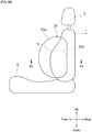
FIG. 1 is a perspective view illustrating the outer shape of a vehicle seat. -
FIG. 2 is a perspective view illustrating a seat frame of the seat ofFIG. 1 . -
FIG. 3A is a schematic side view of a side airbag apparatus according to an embodiment mounted on the seat ofFIG. 1 , illustrating the state prior to the deployment of the airbag as seen from the outside in the width direction of the vehicle. -
FIG. 3B is a schematic side view of a side airbag apparatus according to an embodiment mounted on the seat ofFIG. 1 , illustrating the state after the deployment of the airbag as seen from the outside in the width direction of the vehicle. -
FIG. 4 is a cross sectional view along line A1-A1 ofFIG. 3A , in addition to also being a view illustrating the state prior to the deployment of the airbag, along with the vehicle seat and a side panel. -
FIG. 5 is a cross sectional view along line A2-A2 ofFIG. 3B , in addition to also being a view illustrating the state after the deployment of the airbag, along with the vehicle seat. -
FIG. 6A is a cross sectional view illustrating the state in which a support part of the side airbag apparatus according to the embodiment is disposed at a first rotation position. -
FIG. 6B is a cross sectional view illustrating the state in which the support part of the side airbag apparatus according to the embodiment is disposed at a second rotation position. -
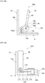
FIG. 7A is a view illustrating a variable mechanism according to another embodiment, illustrating the state in which a support part is disposed at a first rotation position. -
FIG. 7B is a view illustrating the variable mechanism according to another embodiment, illustrating the state in which the support part is disposed at a second rotation position. -
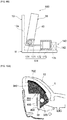
FIG. 8A is a view illustrating a variable mechanism according to yet another embodiment, illustrating the state in which a support part is disposed at a first rotation position. -
FIG. 8B is a view illustrating the variable mechanism according to yet another embodiment, illustrating the state in which the support part is disposed at a second rotation position. -
FIG. 9A is a view illustrating a variable mechanism according to still another embodiment, illustrating the state in which a support part is disposed at a first rotation position. -
FIG. 9B is a view illustrating the variable mechanism according to still another embodiment, illustrating the state in which the support part is disposed at a second rotation position. -
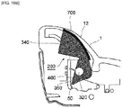
FIG. 10A is a side cross sectional view illustrating the state in which a support part of a side airbag apparatus according to another embodiment is disposed at a first rotation position, along with the seat of the vehicle. -
FIG. 10B is a side cross sectional view illustrating the state in which the support part of the side airbag apparatus according to another embodiment is disposed at a second rotation position, along with the seat of the vehicle. - The side airbag apparatus according to the preferred embodiments of the present invention will be described with reference to the accompanying drawings. In this document, up and down, left and right, and front and rear are defined as follows. When a passenger is seated in a seat in a regular posture, the direction the passenger faces is referred to as the front, the opposite direction is referred to as the rear, and the direction indicating the coordinate axis is referred to as the anteroposterior direction. Moreover, when the passenger is seated in the seat in a regular posture, the right of the passenger is referred to as the right direction, the left of the passenger is referred to as the left direction, and the direction indicating the coordinate axis is referred to as the left and right direction. Similarly, when the passenger is seated in a regular posture, the head direction of the passenger is referred to as up, the waist direction of the passenger is referred to as down, and the direction indicating the coordinate axis is referred to as the vertical direction. Moreover, "inside" represented in the drawings refers to the inside in the width direction of the vehicle or the passenger side, while "outside" represented therein refers to the outside in the width direction of the vehicle or the door panel side.
- As illustrated in
FIG. 1 , avehicle seat 100 includes: a seat back 1 supporting the back of the passenger; aseat cushion 2 in which the passenger is seated; and aheadrest 3 supporting the head of the passenger. Thevehicle seat 100 is, for example, a driver seat or passenger seat, but may be a rear seat. The seat back 1 has a pair of left and rightside support parts seat frame 1f and aseating frame 2f which form the skeleton of the seat are respectively provided inside the seat back 1 and the seat cushion 2 (seeFIG. 2 ). Theseat frame 1f and theseating frame 2f are obtained by processing metal components or hard resins, and are coupled to each other via areclining mechanism 4. A pad 16 (seeFIG. 4 ) made of a urethane foaming material, etc. is provided on the surface and periphery of theseat frame 1f and theseating frame 2f, wherein the surface of thepad 16 is covered with a skin 14 (seeFIG. 4 ) such as leather or fabric. - As illustrated in
FIG. 2 , theseat frame 1f has a pair of side frames 10, 10 which are disposed so as to be separated into the left and right. The pair of left and right side frames 10, 10 extend in the vertical direction, wherein the upper ends thereof are coupled to each other via an upper frame, while the lower ends thereof are coupled to each other via a lower frame. As illustrated inFIG. 4 , theside frame 10 has an L shaped cross section, wherein such an L shaped cross section is configured by: a frameside wall part 10a extending in the anteroposterior direction; and a framerear wall part 10b extending from the rear end of the frameside wall part 10a to the inside in the width direction of the vehicle. When aside airbag apparatus 20 is fixed on the inner surface of this frameside wall part 10a, theside airbag apparatus 20 is attached to theseat frame 1f. - As illustrated in
FIG. 4 , theside airbag apparatus 20 has anairbag 30, aninflator 32, and acover 34 covering theairbag 30 and theinflator 32. Thecover 34 is, for example, made of fabric and flexible. Inside theside support part 12, theside airbag apparatus 20 is housed in a space with apad 16 not disposed therein.Seams skin 14 in theside support part 12 are interwoven and coupled to each other by sewing. Note that among theseseams front seam 18 is cleft when theairbag 30 is deployed (seeFIG. 5 ). - The
airbag 30 is formed in a bag shape, for example, by sewing or adhering one or more base cloths, etc. at (an) appropriate position(s), and receives the supply of gas for expansion and deployment so as to deform from the flat state to the deployment state. Theairbag 30 in the flat state is, for example, wound or folded in a roll form, an accordion form, or a combination thereof. Theairbag 30 is expanded and deployed on the side of thevehicle seat 100 using gas supplied from theinflator 32. For example, theairbag 30 is expanded and deployed towards the front of and above theside support part 12, and arranged between the passenger in a regular seating state and adoor trim 25 so as to restrain the passenger. As illustrated inFIGS. 3A and3B , such anairbag 30 may have, for example, twoexpansion parts FIG. 5 , theexpansion part 30a may be expanded and deployed towards the front of theside support part 12, while theexpansion part 30b may be expanded and deployed inside theexpansion part 30a in the width direction of the vehicle. - The inflator 32 supplies, to the
airbag 30, gas for expansion and deployment. The inflator 32 is electrically connected to a vehicle side ECU. For example, theinflator 32 receives a signal (which has detected the impact upon a side collision of the vehicle) from the vehicle side ECU and operates to instantly supply the gas towards theairbag 30. As the inflator 32, a variety can be employed including a gas generating agent, compression gas, or those into which both of these are filled. As one example, theinflator 32 has an ignition apparatus at the open end of a bottomed cylinder. In addition, when the gas generating agent in the cylinder is ignited using this ignition apparatus, gas is generated so as to supply the gas (for expansion and deployment) into theairbag 30 from multiple injection holes located on the peripheral surface of the cylinder. - As illustrated in
FIG. 4 , theside airbag apparatus 20 includes asupport plate 36 to which theinflator 32 is fixed. Thesupport plate 36 is made of a flat plate shaped member extending in the anteroposterior direction, and formed of, for example, metal components or hard resins. The length in the anteroposterior direction of thesupport plate 36 is approximately identical to that of the frameside wall part 10a of theside frame 10. The outer surface of thesupport plate 36 in the width direction of the vehicle faces the inner surface of the frameside wall part 10a. The inner surface of thesupport plate 36 in the width direction of the vehicle has areaction force surface 40 for receiving the deployment force of theairbag 30 upon expanding and deploying theairbag 30. Thereaction force surface 40 can be, for example, a portion over the entire inner surface of thesupport plate 36 in the width direction of the vehicle. Thereaction force surface 40 directs the direction in which theairbag 30 is expanded and deployed in order to receive the deployment force of theairbag 30. That is, thereaction force surface 40 controls the deployment direction of theairbag 30. - The inflator 32 is fixed to an intermediate part in the anteroposterior direction of the
support plate 36. The fixing of the inflator 32 will be described in detail with reference toFIG. 6A , wherein the inflator 32 is first housed inside theairbag 30. For example, theinflator 32 of the cylinder extending in the vertical direction is housed inside theexpansion part 30b, wherein the outer periphery of the cylinder has a pair of upper andlower stud bolts 41 which protrude outside theexpansion part 30b towards the outside in the width direction of the vehicle. Thestud bolts 41 penetrate through the intermediate part in the anteroposterior direction of thesupport plate 36 so as to be fastened and fixed to thesupport plate 36 from the outside in the width direction of the vehicle using anut 42. In this fastened and fixed state, the base cloth making up theexpansion part 30b is pressed against thereaction force surface 40 of thesupport plate 36 using theinflator 32. Accordingly, theinflator 32 and theairbag 30 are co-fastened with thesupport plate 36, not theside frame 10, using thestud bolts 41 and thenut 42. - As illustrated in
FIGS. 6A and6B , theside airbag apparatus 20 includes avariable mechanism 50 configured to attach thesupport plate 36 to the frameside wall part 10a of theside frame 10 such that the angle of thereaction force surface 40 is variable with respect to the frameside wall part 10a. Thevariable mechanism 50 is provided between thesupport plate 36 and the frameside wall part 10a. For example, thevariable mechanism 50 has arotation holding part 52 provided on the rear side of thevehicle seat 100, along with anactuator 54 provided on the front side of thevehicle seat 100. However, in another embodiment, therotation holding part 52 and theactuator 54 may be reversely disposed in the front and rear. - The
rotation holding part 52 rotatably supports the rear end (first end) of thesupport plate 36 with respect to the frameside wall part 10a. Therotation holding part 52 configures the fulcrum when the front end (second end) of thesupport plate 36 rotates in the direction away from the frameside wall part 10a. Moreover, therotation holding part 52 configures the attachment point of theside airbag apparatus 20 to theseat frame 1f. Such arotation holding part 52 can be, for example, configured by a hinge. However, this is not limited thereto. - The
actuator 54 applies force to the front end of thesupport plate 36 so as to rotate thesupport plate 36 about therotation holding part 52. Specifically, theactuator 54 is fixed to the inner surface of the frameside wall part 10a in the width direction of the vehicle so as to apply force to the front end of thesupport plate 36 from the outside in the width direction of the vehicle to the inside in the width direction of the vehicle. As a result, as thesupport plate 36 is rotated, the angle of thereaction force surface 40 is varied with respect to the frameside wall part 10a. As with therotation holding part 52, theactuator 54 configures the attachment point of theside airbag apparatus 20 to theseat frame 1f. - According to another embodiment, the
actuator 54 may apply force to a portion other than the front end of thesupport plate 36. For example, in a portion of thesupport plate 36, force from theactuator 54 may be applied to a portion between the front end and the rear end opposite the front end. In so doing, regarding thesupport plate 36 having thereaction force surface 40 for receiving the deployment force of theairbag 30, the center part thereof can be supported by the actuator 54 from the outside in the width direction of the vehicle. - The
actuator 54 can be configured of various power sources and mechanical mechanisms. For example, a motor, solenoid, hydraulic or pneumatic cylinder, or piezoelectric element can be used as theactuator 54. The motor may be combined with various mechanisms including, for example, a ball screw, gear, or rail. As one example, the motor as theactuator 54 is fixed to the frameside wall part 10a, a ball screw is coupled to an output shaft of this motor, and a ball nut screwed to this ball screw is fixed to the outer surface of thesupport plate 36 in the width direction of the vehicle. Alternatively, a cylinder as theactuator 54 is fixed to the frameside wall part 10a, while a piston rod of this cylinder is fixed to the outer surface of thesupport plate 36 in the width direction of the vehicle. - The
actuator 54 is electrically connected to an ECU. This ECU may be the same as the vehicle side ECU connected to theinflator 32. Theactuator 54 is operated based on a signal received from the ECU so as to rotate thesupport plate 36. For example, if a sensor is provided in the vehicle in order to detect the physique of the passenger on thevehicle seat 100, the ECU operates theactuator 54 such that thesupport plate 36 is positioned at a predetermined rotation position, in accordance with the physique of the passenger detected by this sensor. As one example, if the physique of the passenger is small, the rotation position of thesupport plate 36 is the position illustrated inFIG. 6A . In contrast, if the physique of the passenger is large, the rotation position of thesupport plate 36 is the position illustrated inFIG. 6B . In addition, as the physique of the passenger increases, the rotation position of thesupport plate 36 may be increased from the position illustrated inFIG. 6A to the position illustrated inFIG. 6B . The abovementioned sensor is not limited along as it can detect physiques, wherein, for example, a weight sensor embedded in thevehicle seat 100 can be used. - In another embodiment, the
actuator 54 may be operated in accordance with conditions other than the physique of the passenger. For example, the ECU may operate theactuator 54 such that thesupport plate 36 is positioned at a predetermined rotation position, in accordance with the vehicle speed detected by the sensor provided in the vehicle. As one example, if the vehicle speed is low, the rotation position of thesupport plate 36 is the position illustrated inFIG. 6A . In contrast, if the vehicle speed is high, the rotation position of thesupport plate 36 is the position illustrated inFIG. 6B . In addition, as the vehicle speed increases, the rotation position of thesupport plate 36 may be increased from the position illustrated inFIG. 6A to the position illustrated inFIG. 6B . - As described above, the
side airbag apparatus 20 according to the present embodiment includes thesupport plate 36 and thevariable mechanism 50, in addition to theairbag 30 and theinflator 32. In addition, thesupport plate 36 has areaction force surface 40 for receiving the deployment force of theairbag 30 upon expanding and deploying theairbag 30, in addition to fixing theinflator 32. Moreover, thevariable mechanism 50 is configured to attach thesupport plate 36 to theseat frame 1f such that the angle of thereaction force surface 40 is variable with respect to theseat frame 1f. - According to such a configuration, when the angle of the
reaction force surface 40 is changed using thevariable mechanism 50, the direction (deployment direction) for directing the expansion and deployment of theairbag 30 can be adjusted. As a result, once theside airbag apparatus 20 is attached to theseat frame 1f, the deployment direction of theairbag 30 is not fixed in one direction, but rather the deployment direction of theairbag 30 can be appropriately controlled. For example, the deployment direction can be changed to a deployment direction which responds to various conditions (such as the vehicle speed or the physique of the passenger seated in the vehicle seat 100) and is suitable for each condition. - In particular, the
variable mechanism 50 has: therotation holding part 52 rotatably supporting the rear end of thesupport plate 36 on theseat frame 1f; and theactuator 54 for applying force to the front end of thesupport plate 36 so as to rotate thesupport plate 36 about therotation holding part 52. In so doing, because the angle of thereaction force surface 40 can be varied by rotating thesupport plate 36, the deployment direction of theairbag 30 can be adjusted via a relatively simple structure. Moreover, the region for applying force for rotation serves as the region (front end of thesupport plate 36 opposite the rear end in the anteroposterior direction of the vehicle seat 100) as distant as possible from the fulcrum (rear end of the support plate 36) and therefore is easily rotated by a small force. - Moreover, the
actuator 54 is fixed to theseat frame 1f. As a result, the attachment point of theside airbag apparatus 20 to theseat frame 1f can be configured by theactuator 54. - The embodiments described above are for ease of understanding of the present invention and are not intended to be construed as limiting the present invention. Each element included in each embodiment, as well as the arrangement, materials, conditions, shape, and size thereof, is not limited to those illustrated, but rather can be appropriately changed. For example, as a support part having the
reaction force surface 40, a case shaped housing, etc. may be used instead of thesupport plate 36. Moreover, as thevariable mechanism 50, those other than the combination of therotation holding part 52 and theactuator 54 may be used. For example, a slide mechanism and a cam mechanism may be combined with an actuator as a power source such as a motor. - In another embodiment, as illustrated in
FIGS. 7A and7B , avariable mechanism 500 has anactuator 140 for rotating the support plate 36 (support part) with respect to theseat frame 1f. Theactuator 140 has apower source 142 and apower transmission part 144, wherein thepower transmission part 144 transmits power from thepower source 142 to thesupport plate 36 in order to rotate thesupport plate 36. In this case, thepower source 142 is attached to theseat frame 1f, while thepower transmission part 144 is coupled to thepower source 142 and thesupport plate 36, such that thevariable mechanism 500 attaches thesupport plate 36 to theseat frame 1f. - The
power transmission part 144 has, for example: apinion gear 150; ashaft 151 with one end thereof coupled to the shaft center of thepinion gear 150, with the other end thereof coupled to the rear end of thesupport plate 36; arack 152 engaging with thepinion gear 150; apiston 153 coupled to one end of therack 152; and acylinder 154 slidably housing thepiston 153. Thepower source 142 is fixed, for example, to thecylinder 154, as well as to the frameside wall part 10a or the framerear wall part 10b of theseat frame 1f, and configured by a gas generator capable of supplying high pressure gas into thecylinder 154. Thepower source 142 is electrically connected to the ECU and operated based on the signal received from the ECU. For example, upon changing the rotation position of thesupport plate 36 from the position illustrated inFIG. 7A to the position illustrated inFIG. 7B , the gas generator of thepower source 142 is operated so as to supply high pressure gas into thecylinder 154. Thereupon, this acts on thepiston 153, such that therack 152 is moved in the direction of an arrow 156 (forward) so as to rotate thepinion gear 150. As a result, theshaft 151 is rotated so as to rotate thesupport plate 36. The rotation angle of the support plate 36 (that is, the angle of the reaction force surface 40) is variable in multiple stages in accordance with the amount of high pressure gas supplied from the gas generator. -
FIGS. 8A and8B illustrate yet another embodiment regarding thepower source 142 and thepower transmission part 144 of theactuator 140. Thepower source 142 is configured by a motor and, for example, fixed to the framerear wall part 10b of theseat frame 1f. Thepower transmission part 144 has: aninitial gear 160 coupled to anoutput shaft 142a of the motor of thepower source 142; afinal gear 162 engaging with theinitial gear 160; and ashaft 163 coupled to the center of thefinal gear 162, with theshaft 163 coupled to the rear end of thesupport plate 36. The motor of thepower source 142 is electrically connected to the ECU and operated based on the signal received from the ECU. For example, the motor of thepower source 142 is driven upon changing the rotation position of thesupport plate 36 from the position illustrated inFIG. 8A to the position illustrated inFIG. 8B . Thereupon, the rotation of the motor is transmitted from theoutput shaft 142a to theinitial gear 160 and thefinal gear 162, such that theshaft 163 is rotated so as to rotate thesupport plate 36. The rotation angle of the support plate 36 (that is, the angle of the reaction force surface 40) is variable in multiple stages in accordance with the rotation amount of the motor of thepower source 142. -
FIGS. 8A and8B illustrate still another embodiment regarding thepower source 142 and thepower transmission part 144 of theactuator 140. Thepower transmission part 144 has: acoupling member 171 made of wire, etc.; apiston 172 coupled to the base end side of thecoupling member 171; acylinder 173 slidably housing thepiston 172; and ashaft 174 around which the tip side of thecoupling member 171 is wound, with theshaft 174 coupled to the rear end of thesupport plate 36. Thepower source 142 is fixed, for example, to thecylinder 173, as well as to the framerear wall part 10b of theseat frame 1f, and configured by the gas generator capable of supplying high pressure gas into thecylinder 174. The gas generator of thepower source 142 is electrically connected to the ECU, and operated based on the signal received from the ECU. For example, upon changing the rotation position of thesupport plate 36 from the position illustrated inFIG. 9A to the position illustrated inFIG. 9B , the gas generator of thepower source 142 is operated so as to supply high pressure gas into thecylinder 174. Thereupon, this acts on thepiston 172, such that thecoupling member 171 is moved in the direction of an arrow 176 (outside the vehicle). As a result, theshaft 174 is rotated so as to rotate thesupport plate 36. The rotation angle of the support plate 36 (that is, the angle of the reaction force surface 40) is variable in multiple stages in accordance with the amount of high pressure gas supplied from the gas generator of thepower source 142. - As described above, even in the
variable mechanism 500 having the actuator 140 illustrated in the abovementionedFIGS. 7A to 9B , because the angle of thereaction force surface 40 can be varied by rotating thesupport plate 36, the deployment direction of the airbag can be adjusted via a relatively simple structure. Note that inFIGS. 7A to 9B , the illustration of other configurations (including theairbag 30, theinflator 32, etc.) of theside airbag apparatus 20 is omitted, with this point similar to that illustrated inFIG. 4 , etc. - In another embodiment, the
side airbag apparatus 20 may be employed to deform a seat back of the vehicle in accordance with the physique of the passenger. In such aside airbag apparatus 200, for example, as illustrated inFIGS. 10A and10B , a pressingmember 700 capable of pressing a seat back 1 from the inside thereof is attached to acover 340 covering the airbag and aninflator 320. The pressingmember 700 has a surface which is formed to be hard, with such a hard surface pressing the seat back 1. The hard surface of thepressing member 700 is, for example, formed of resin, a hard surface of the entire module formed by 3D compression, or a hybrid cover (partially hard surface formed by felt pressing). The region of the seat back 1 pressed by the pressingmember 700 can serve as theside support part 12. Thecover 340 is in contact with asupport plate 360, wherein, as thesupport plate 360 is movable, thecover 340 is movable. Therefore, the pressingmember 700 attached to thecover 340 is also movable as the angle of areaction force surface 400 of thesupport plate 360 is varied by thevariable mechanism 50, such that this movability causes the seat back 1 to be pressed from the inside thereof and deformed. In this manner, theside airbag apparatus 200 having the pressingmember 700 is equipped with a physique adjustment mechanism. That is, because the seat back 1 can be deformed in accordance with the physique and preference of the passenger, the fit feeling of the vehicle seat to the passenger can be improved. - In another embodiment, the
side airbag apparatuses airbag 30 to be expanded and deployed may be arranged, for example, between thevehicle seat 100 and a center console of the vehicle. The center console is, for example, disposed between two vehicle seats. - Moreover, application is also possible for airbag apparatuses other than the side airbag apparatuses. For example, application can be made to a passenger seat airbag, knee airbag, driver airbag, curtain airbag, etc. Upon the application thereof, the attachment region of the support part (support plate 36) to the vehicle side configuration (vehicle body) using the
variable mechanism 50 may be a portion other than the seat frame. As one example, in the case of the passenger seat airbag, a metal instrument panel reinforcement provided inside an instrument panel with the width direction of the vehicle functioning as the longitudinal direction can serve as this attachment region. Moreover, in the case of the knee airbag, in addition to the instrument panel reinforcement, a center brace, front body pillar, column cover of a steering column, glove box, etc. can serve as this attachment region. - 1...seat back, 1f...seat frame, 2...seat cushion, 2f...seating frame, 3...headrest, 4...reclining mechanism, 10...side frame, 10a...frame side wall part, 10b...frame rear wall part, 12...side support part, 14...skin, 16...pad, 18, 22, 24...seam, 20...side airbag apparatus, 25...door trim, 30...airbag, 30a...expansion part, 30b...expansion part, 32...inflator, 34...cover, 36...support plate (support part), 40...reaction force surface, 41...stud bolt, 42...nut, 50...variable mechanism, 52...rotation holding part, 54...actuator, 100...vehicle seat, 140...actuator, 142...power source, 142a...output shaft, 144...power transmission part, 150...pinion gear, 151...shaft, 152...rack, 153...piston, 154...cylinder, 160...initial gear, 162...final gear, 163...shaft, 171...coupling member, 172...piston, 173...cylinder, 174...shaft, 200...side airbag apparatus, 320...inflator, 340...cover, 360...support plate, 400...reaction force surface, 500...variable mechanism, 700...pressing member
Claims (11)
- A side airbag apparatus attached to a seat frame of a vehicle seat, the side airbag apparatus comprising:an airbag;an inflator for supplying, to the airbag, gas for expansion and deployment;a support part having a reaction force surface for receiving the deployment force of this airbag upon expanding and deploying the airbag, with the inflator fixed to the support part; anda variable mechanism configured to attach the support part to the seat frame such that the angle of the reaction force surface is variable with respect to the seat frame.
- The side airbag apparatus according to claim 1;
wherein the variable mechanism includes an actuator for rotating the support part to the seat frame; and
wherein the actuator includes:a power source attached to the seat frame; anda power transmission part which couples the power source and the support part and transmits power from the power source to the support part in order to rotate the support part. - The side airbag apparatus according to claim 1; wherein the variable mechanism includes:a rotation holding part for rotatably supporting a first end of the support part on the seat frame; andan actuator for applying force to a portion different from the first end in a portion of the support part so as to rotate the support part about the rotation holding part.
- The side airbag apparatus according to claim 3, wherein the portion different from the first end in the portion of the support part is the second end opposite the first end in the anteroposterior direction of the seat.
- The side airbag apparatus according to claim 3, wherein the portion different from the first end in the portion of the support part is a portion between the second end (opposite the first end in the anteroposterior direction of the seat) and the first end.
- The side airbag apparatus according to any one of claims 3 to 5, wherein the actuator is fixed to the seat frame.
- The side airbag apparatus according to any one of claims 4 to 6, wherein the rotation holding part is provided on the rear side of the seat, while the actuator is provided on the front side of the seat.
- The side airbag apparatus according to any one of claims 2 to 7, wherein the actuator is operated such that the support part is positioned at a predetermined rotation position in accordance with the physique of a passenger on the seat detected by a sensor provided in the vehicle.
- The side airbag apparatus according to any one of claims 2 to 7, wherein the actuator is operated such that the support part is positioned at a predetermined rotation position in accordance with the vehicle speed detected by a sensor provided in the vehicle.
- The side airbag apparatus according to any one of claims 1 to 9; wherein:the support part includes a plate shaped member extending in the anteroposterior direction of the seat; andthe inflator is fixed to an intermediate part in the anteroposterior direction of the support part.
- The side airbag apparatus according to any one of claims 1 to 10; further comprising:a cover which is attached to the support part and covers the airbag; anda pressing member which is attached to the cover and is capable of pressing a seat back (having an internal seat frame) from the inside thereof;wherein, as the angle of the reaction force surface is varied by the variable mechanism, the pressing member is movable so as to reshape the seat back.
Applications Claiming Priority (1)
| Application Number | Priority Date | Filing Date | Title |
|---|---|---|---|
| JP2018234421A JP6981955B2 (en) | 2018-12-14 | 2018-12-14 | Side airbag device |
Publications (2)
| Publication Number | Publication Date |
|---|---|
| EP3666604A1 true EP3666604A1 (en) | 2020-06-17 |
| EP3666604B1 EP3666604B1 (en) | 2021-10-13 |
Family
ID=68917465
Family Applications (1)
| Application Number | Title | Priority Date | Filing Date |
|---|---|---|---|
| EP19216320.2A Active EP3666604B1 (en) | 2018-12-14 | 2019-12-13 | Side airbag apparatus |
Country Status (4)
| Country | Link |
|---|---|
| US (1) | US11235728B2 (en) |
| EP (1) | EP3666604B1 (en) |
| JP (1) | JP6981955B2 (en) |
| CN (1) | CN111319579B (en) |
Families Citing this family (4)
| Publication number | Priority date | Publication date | Assignee | Title |
|---|---|---|---|---|
| JP7509075B2 (en) * | 2021-04-23 | 2024-07-02 | トヨタ紡織株式会社 | Seat device |
| US11603070B1 (en) * | 2021-10-15 | 2023-03-14 | Ford Global Technologies, Llc | Vehicle seat including movable airbag |
| CN114802075A (en) * | 2022-04-24 | 2022-07-29 | 盐城默成汽车安全系统有限公司 | Novel safety airbag |
| US12617364B2 (en) * | 2024-09-16 | 2026-05-05 | Ford Global Technologies, Llc | Side airbag assembly |
Citations (12)
| Publication number | Priority date | Publication date | Assignee | Title |
|---|---|---|---|---|
| JPH07117600A (en) * | 1993-10-28 | 1995-05-09 | Mitsubishi Motors Corp | Rear seat airbag device |
| JPH1071918A (en) * | 1997-07-08 | 1998-03-17 | Mazda Motor Corp | Energy absorption structure on the side of the vehicle |
| US6220624B1 (en) * | 2000-02-10 | 2001-04-24 | Trw Vehicle Safety Systems Inc. | Mounting bracket for seat mounted air bag |
| WO2001044026A1 (en) * | 1999-12-14 | 2001-06-21 | Breed Automotive Technology, Inc. | Airbag deployment directional controller |
| DE10253472A1 (en) * | 2002-11-16 | 2004-06-17 | Acts Gmbh & Co. Kg | Airbag Module for a vehicle which is rotatably mounted in the armrest of the seat so that the opening direction of the airbag can be changed |
| KR20040095385A (en) * | 2003-04-28 | 2004-11-15 | 현대자동차주식회사 | Airbag system of a head rest type for a passenger in the rear seat |
| WO2012157099A1 (en) | 2011-05-18 | 2012-11-22 | トヨタ自動車株式会社 | Seat structural member and vehicle seat using same |
| JP2015168295A (en) | 2014-03-05 | 2015-09-28 | 三菱自動車工業株式会社 | Side airbag device for vehicle |
| JP2016107721A (en) | 2014-12-03 | 2016-06-20 | トヨタ自動車株式会社 | Far side airbag device for vehicle |
| US20170088078A1 (en) * | 2015-09-30 | 2017-03-30 | Fuji Jukogyo Kabushiki Kaisha | Vehicle occupant protection device |
| WO2017209192A1 (en) | 2016-06-01 | 2017-12-07 | オートリブ ディベロップメント エービー | Occupant protection device |
| US20180304847A1 (en) * | 2017-04-20 | 2018-10-25 | Ford Global Technologies, Llc | Rotatably supported airbag |
Family Cites Families (16)
| Publication number | Priority date | Publication date | Assignee | Title |
|---|---|---|---|---|
| DE19548339C2 (en) * | 1995-12-22 | 1998-05-28 | Daimler Benz Ag | Headrest for a vehicle seat |
| JP2938835B2 (en) * | 1997-07-08 | 1999-08-25 | マツダ株式会社 | Energy absorption structure on the side of the vehicle |
| US7874576B2 (en) * | 2009-04-16 | 2011-01-25 | Toyota Motor Engineering & Manufacturing North America, Inc. | Adjustable airbag systems for vehicles |
| JP5382199B2 (en) * | 2010-11-17 | 2014-01-08 | トヨタ自動車株式会社 | Side airbag device for vehicle |
| JP5514758B2 (en) * | 2011-03-17 | 2014-06-04 | 富士重工業株式会社 | Side airbag device, occupant protection device, and occupant protection method |
| JP5747927B2 (en) * | 2013-02-12 | 2015-07-15 | トヨタ自動車株式会社 | Vehicle seat |
| US20150108744A1 (en) * | 2013-10-17 | 2015-04-23 | Ford Global Technologies,Llc | Integrated side impact and rear occupant front impact protection bolsters |
| EP3170703B1 (en) * | 2014-07-14 | 2019-03-13 | TS Tech Co., Ltd. | Side air bag device |
| JP6149849B2 (en) * | 2014-11-25 | 2017-06-21 | トヨタ自動車株式会社 | Far-side airbag device for vehicles |
| JP6271622B2 (en) * | 2016-03-18 | 2018-01-31 | 株式会社Subaru | Airbag device |
| JP6504098B2 (en) * | 2016-04-08 | 2019-04-24 | トヨタ自動車株式会社 | Occupant protection device |
| KR20180009415A (en) * | 2016-07-18 | 2018-01-29 | 현대다이모스(주) | Side airbag guide and seat with side aribag for vehicles using same |
| JP6658585B2 (en) * | 2017-02-03 | 2020-03-04 | トヨタ自動車株式会社 | Vehicle seats equipped with side airbag devices |
| US20190248322A1 (en) * | 2018-02-12 | 2019-08-15 | Autoliv Asp, Inc. | Airbag systems with tether pretensioning and load limiting |
| CN111918795B (en) * | 2018-04-05 | 2022-11-01 | 奥托立夫开发公司 | Side airbag device and vehicle seat having the same |
| JP7056508B2 (en) * | 2018-10-19 | 2022-04-19 | 豊田合成株式会社 | Vehicle occupant protection device |
-
2018
- 2018-12-14 JP JP2018234421A patent/JP6981955B2/en active Active
-
2019
- 2019-12-03 CN CN201911221384.9A patent/CN111319579B/en active Active
- 2019-12-13 EP EP19216320.2A patent/EP3666604B1/en active Active
- 2019-12-13 US US16/713,129 patent/US11235728B2/en active Active
Patent Citations (12)
| Publication number | Priority date | Publication date | Assignee | Title |
|---|---|---|---|---|
| JPH07117600A (en) * | 1993-10-28 | 1995-05-09 | Mitsubishi Motors Corp | Rear seat airbag device |
| JPH1071918A (en) * | 1997-07-08 | 1998-03-17 | Mazda Motor Corp | Energy absorption structure on the side of the vehicle |
| WO2001044026A1 (en) * | 1999-12-14 | 2001-06-21 | Breed Automotive Technology, Inc. | Airbag deployment directional controller |
| US6220624B1 (en) * | 2000-02-10 | 2001-04-24 | Trw Vehicle Safety Systems Inc. | Mounting bracket for seat mounted air bag |
| DE10253472A1 (en) * | 2002-11-16 | 2004-06-17 | Acts Gmbh & Co. Kg | Airbag Module for a vehicle which is rotatably mounted in the armrest of the seat so that the opening direction of the airbag can be changed |
| KR20040095385A (en) * | 2003-04-28 | 2004-11-15 | 현대자동차주식회사 | Airbag system of a head rest type for a passenger in the rear seat |
| WO2012157099A1 (en) | 2011-05-18 | 2012-11-22 | トヨタ自動車株式会社 | Seat structural member and vehicle seat using same |
| JP2015168295A (en) | 2014-03-05 | 2015-09-28 | 三菱自動車工業株式会社 | Side airbag device for vehicle |
| JP2016107721A (en) | 2014-12-03 | 2016-06-20 | トヨタ自動車株式会社 | Far side airbag device for vehicle |
| US20170088078A1 (en) * | 2015-09-30 | 2017-03-30 | Fuji Jukogyo Kabushiki Kaisha | Vehicle occupant protection device |
| WO2017209192A1 (en) | 2016-06-01 | 2017-12-07 | オートリブ ディベロップメント エービー | Occupant protection device |
| US20180304847A1 (en) * | 2017-04-20 | 2018-10-25 | Ford Global Technologies, Llc | Rotatably supported airbag |
Also Published As
| Publication number | Publication date |
|---|---|
| US11235728B2 (en) | 2022-02-01 |
| CN111319579B (en) | 2022-05-31 |
| US20200189515A1 (en) | 2020-06-18 |
| JP2020093736A (en) | 2020-06-18 |
| JP6981955B2 (en) | 2021-12-17 |
| EP3666604B1 (en) | 2021-10-13 |
| CN111319579A (en) | 2020-06-23 |
Similar Documents
| Publication | Publication Date | Title |
|---|---|---|
| US11235728B2 (en) | Side airbag apparatus | |
| JP5099226B2 (en) | Vehicle seat | |
| JP5030968B2 (en) | Crew restraint device for automobile | |
| EP3900985B1 (en) | Side airbag device, vehicle seat provided with same, and method for manufacturing side airbag device | |
| US11214225B2 (en) | Passenger protection apparatus | |
| JP5747927B2 (en) | Vehicle seat | |
| EP3604047B1 (en) | Passenger protection device | |
| US20160297392A1 (en) | Airbag assemblies for vehicles with generous leg room | |
| KR20180002763A (en) | Riding protection device | |
| CN109383437A (en) | Side air bag device | |
| JP2009520627A5 (en) | ||
| JP2018012476A (en) | Vehicular occupant restraint device | |
| US11498509B2 (en) | Roof mounted passenger airbag | |
| CN115362087A (en) | Occupant protection device | |
| US6095550A (en) | Vehicle occupant restraint apparatus | |
| JP2019098921A (en) | Rear seat side air bag device | |
| JP6988419B2 (en) | Vehicle seat | |
| JP2011143856A (en) | Airbag device | |
| JP2011093479A (en) | Seat for vehicle | |
| JP7217343B2 (en) | passenger protection device | |
| JP7407935B2 (en) | side airbag device | |
| JP2019137305A (en) | Front center air bag device for vehicle | |
| CN115052786A (en) | Side airbag device | |
| JP4254789B2 (en) | Energy absorption device for vehicle side |
Legal Events
| Date | Code | Title | Description |
|---|---|---|---|
| PUAI | Public reference made under article 153(3) epc to a published international application that has entered the european phase |
Free format text: ORIGINAL CODE: 0009012 |
|
| STAA | Information on the status of an ep patent application or granted ep patent |
Free format text: STATUS: REQUEST FOR EXAMINATION WAS MADE |
|
| 17P | Request for examination filed |
Effective date: 20191213 |
|
| AK | Designated contracting states |
Kind code of ref document: A1 Designated state(s): AL AT BE BG CH CY CZ DE DK EE ES FI FR GB GR HR HU IE IS IT LI LT LU LV MC MK MT NL NO PL PT RO RS SE SI SK SM TR |
|
| AX | Request for extension of the european patent |
Extension state: BA ME |
|
| STAA | Information on the status of an ep patent application or granted ep patent |
Free format text: STATUS: EXAMINATION IS IN PROGRESS |
|
| 17Q | First examination report despatched |
Effective date: 20201127 |
|
| GRAP | Despatch of communication of intention to grant a patent |
Free format text: ORIGINAL CODE: EPIDOSNIGR1 |
|
| STAA | Information on the status of an ep patent application or granted ep patent |
Free format text: STATUS: GRANT OF PATENT IS INTENDED |
|
| INTG | Intention to grant announced |
Effective date: 20210507 |
|
| GRAS | Grant fee paid |
Free format text: ORIGINAL CODE: EPIDOSNIGR3 |
|
| GRAA | (expected) grant |
Free format text: ORIGINAL CODE: 0009210 |
|
| STAA | Information on the status of an ep patent application or granted ep patent |
Free format text: STATUS: THE PATENT HAS BEEN GRANTED |
|
| AK | Designated contracting states |
Kind code of ref document: B1 Designated state(s): AL AT BE BG CH CY CZ DE DK EE ES FI FR GB GR HR HU IE IS IT LI LT LU LV MC MK MT NL NO PL PT RO RS SE SI SK SM TR |
|
| REG | Reference to a national code |
Ref country code: GB Ref legal event code: FG4D |
|
| REG | Reference to a national code |
Ref country code: CH Ref legal event code: EP |
|
| REG | Reference to a national code |
Ref country code: DE Ref legal event code: R096 Ref document number: 602019008334 Country of ref document: DE |
|
| REG | Reference to a national code |
Ref country code: IE Ref legal event code: FG4D |
|
| REG | Reference to a national code |
Ref country code: AT Ref legal event code: REF Ref document number: 1437971 Country of ref document: AT Kind code of ref document: T Effective date: 20211115 |
|
| REG | Reference to a national code |
Ref country code: LT Ref legal event code: MG9D |
|
| REG | Reference to a national code |
Ref country code: NL Ref legal event code: MP Effective date: 20211013 |
|
| REG | Reference to a national code |
Ref country code: AT Ref legal event code: MK05 Ref document number: 1437971 Country of ref document: AT Kind code of ref document: T Effective date: 20211013 |
|
| PG25 | Lapsed in a contracting state [announced via postgrant information from national office to epo] |
Ref country code: RS Free format text: LAPSE BECAUSE OF FAILURE TO SUBMIT A TRANSLATION OF THE DESCRIPTION OR TO PAY THE FEE WITHIN THE PRESCRIBED TIME-LIMIT Effective date: 20211013 Ref country code: LT Free format text: LAPSE BECAUSE OF FAILURE TO SUBMIT A TRANSLATION OF THE DESCRIPTION OR TO PAY THE FEE WITHIN THE PRESCRIBED TIME-LIMIT Effective date: 20211013 Ref country code: FI Free format text: LAPSE BECAUSE OF FAILURE TO SUBMIT A TRANSLATION OF THE DESCRIPTION OR TO PAY THE FEE WITHIN THE PRESCRIBED TIME-LIMIT Effective date: 20211013 Ref country code: BG Free format text: LAPSE BECAUSE OF FAILURE TO SUBMIT A TRANSLATION OF THE DESCRIPTION OR TO PAY THE FEE WITHIN THE PRESCRIBED TIME-LIMIT Effective date: 20220113 Ref country code: AT Free format text: LAPSE BECAUSE OF FAILURE TO SUBMIT A TRANSLATION OF THE DESCRIPTION OR TO PAY THE FEE WITHIN THE PRESCRIBED TIME-LIMIT Effective date: 20211013 |
|
| PG25 | Lapsed in a contracting state [announced via postgrant information from national office to epo] |
Ref country code: IS Free format text: LAPSE BECAUSE OF FAILURE TO SUBMIT A TRANSLATION OF THE DESCRIPTION OR TO PAY THE FEE WITHIN THE PRESCRIBED TIME-LIMIT Effective date: 20220213 Ref country code: SE Free format text: LAPSE BECAUSE OF FAILURE TO SUBMIT A TRANSLATION OF THE DESCRIPTION OR TO PAY THE FEE WITHIN THE PRESCRIBED TIME-LIMIT Effective date: 20211013 Ref country code: PT Free format text: LAPSE BECAUSE OF FAILURE TO SUBMIT A TRANSLATION OF THE DESCRIPTION OR TO PAY THE FEE WITHIN THE PRESCRIBED TIME-LIMIT Effective date: 20220214 Ref country code: PL Free format text: LAPSE BECAUSE OF FAILURE TO SUBMIT A TRANSLATION OF THE DESCRIPTION OR TO PAY THE FEE WITHIN THE PRESCRIBED TIME-LIMIT Effective date: 20211013 Ref country code: NO Free format text: LAPSE BECAUSE OF FAILURE TO SUBMIT A TRANSLATION OF THE DESCRIPTION OR TO PAY THE FEE WITHIN THE PRESCRIBED TIME-LIMIT Effective date: 20220113 Ref country code: NL Free format text: LAPSE BECAUSE OF FAILURE TO SUBMIT A TRANSLATION OF THE DESCRIPTION OR TO PAY THE FEE WITHIN THE PRESCRIBED TIME-LIMIT Effective date: 20211013 Ref country code: LV Free format text: LAPSE BECAUSE OF FAILURE TO SUBMIT A TRANSLATION OF THE DESCRIPTION OR TO PAY THE FEE WITHIN THE PRESCRIBED TIME-LIMIT Effective date: 20211013 Ref country code: HR Free format text: LAPSE BECAUSE OF FAILURE TO SUBMIT A TRANSLATION OF THE DESCRIPTION OR TO PAY THE FEE WITHIN THE PRESCRIBED TIME-LIMIT Effective date: 20211013 Ref country code: GR Free format text: LAPSE BECAUSE OF FAILURE TO SUBMIT A TRANSLATION OF THE DESCRIPTION OR TO PAY THE FEE WITHIN THE PRESCRIBED TIME-LIMIT Effective date: 20220114 Ref country code: ES Free format text: LAPSE BECAUSE OF FAILURE TO SUBMIT A TRANSLATION OF THE DESCRIPTION OR TO PAY THE FEE WITHIN THE PRESCRIBED TIME-LIMIT Effective date: 20211013 |
|
| REG | Reference to a national code |
Ref country code: DE Ref legal event code: R097 Ref document number: 602019008334 Country of ref document: DE |
|
| PG25 | Lapsed in a contracting state [announced via postgrant information from national office to epo] |
Ref country code: SM Free format text: LAPSE BECAUSE OF FAILURE TO SUBMIT A TRANSLATION OF THE DESCRIPTION OR TO PAY THE FEE WITHIN THE PRESCRIBED TIME-LIMIT Effective date: 20211013 Ref country code: SK Free format text: LAPSE BECAUSE OF FAILURE TO SUBMIT A TRANSLATION OF THE DESCRIPTION OR TO PAY THE FEE WITHIN THE PRESCRIBED TIME-LIMIT Effective date: 20211013 Ref country code: RO Free format text: LAPSE BECAUSE OF FAILURE TO SUBMIT A TRANSLATION OF THE DESCRIPTION OR TO PAY THE FEE WITHIN THE PRESCRIBED TIME-LIMIT Effective date: 20211013 Ref country code: MC Free format text: LAPSE BECAUSE OF FAILURE TO SUBMIT A TRANSLATION OF THE DESCRIPTION OR TO PAY THE FEE WITHIN THE PRESCRIBED TIME-LIMIT Effective date: 20211013 Ref country code: EE Free format text: LAPSE BECAUSE OF FAILURE TO SUBMIT A TRANSLATION OF THE DESCRIPTION OR TO PAY THE FEE WITHIN THE PRESCRIBED TIME-LIMIT Effective date: 20211013 Ref country code: DK Free format text: LAPSE BECAUSE OF FAILURE TO SUBMIT A TRANSLATION OF THE DESCRIPTION OR TO PAY THE FEE WITHIN THE PRESCRIBED TIME-LIMIT Effective date: 20211013 Ref country code: CZ Free format text: LAPSE BECAUSE OF FAILURE TO SUBMIT A TRANSLATION OF THE DESCRIPTION OR TO PAY THE FEE WITHIN THE PRESCRIBED TIME-LIMIT Effective date: 20211013 |
|
| PLBE | No opposition filed within time limit |
Free format text: ORIGINAL CODE: 0009261 |
|
| STAA | Information on the status of an ep patent application or granted ep patent |
Free format text: STATUS: NO OPPOSITION FILED WITHIN TIME LIMIT |
|
| 26N | No opposition filed |
Effective date: 20220714 |
|
| REG | Reference to a national code |
Ref country code: BE Ref legal event code: MM Effective date: 20211231 |
|
| PG25 | Lapsed in a contracting state [announced via postgrant information from national office to epo] |
Ref country code: LU Free format text: LAPSE BECAUSE OF NON-PAYMENT OF DUE FEES Effective date: 20211213 Ref country code: IE Free format text: LAPSE BECAUSE OF NON-PAYMENT OF DUE FEES Effective date: 20211213 Ref country code: AL Free format text: LAPSE BECAUSE OF FAILURE TO SUBMIT A TRANSLATION OF THE DESCRIPTION OR TO PAY THE FEE WITHIN THE PRESCRIBED TIME-LIMIT Effective date: 20211013 |
|
| PG25 | Lapsed in a contracting state [announced via postgrant information from national office to epo] |
Ref country code: SI Free format text: LAPSE BECAUSE OF FAILURE TO SUBMIT A TRANSLATION OF THE DESCRIPTION OR TO PAY THE FEE WITHIN THE PRESCRIBED TIME-LIMIT Effective date: 20211013 Ref country code: BE Free format text: LAPSE BECAUSE OF NON-PAYMENT OF DUE FEES Effective date: 20211231 |
|
| PG25 | Lapsed in a contracting state [announced via postgrant information from national office to epo] |
Ref country code: IT Free format text: LAPSE BECAUSE OF FAILURE TO SUBMIT A TRANSLATION OF THE DESCRIPTION OR TO PAY THE FEE WITHIN THE PRESCRIBED TIME-LIMIT Effective date: 20211013 |
|
| P01 | Opt-out of the competence of the unified patent court (upc) registered |
Effective date: 20230507 |
|
| PG25 | Lapsed in a contracting state [announced via postgrant information from national office to epo] |
Ref country code: CY Free format text: LAPSE BECAUSE OF FAILURE TO SUBMIT A TRANSLATION OF THE DESCRIPTION OR TO PAY THE FEE WITHIN THE PRESCRIBED TIME-LIMIT Effective date: 20211013 |
|
| PG25 | Lapsed in a contracting state [announced via postgrant information from national office to epo] |
Ref country code: HU Free format text: LAPSE BECAUSE OF FAILURE TO SUBMIT A TRANSLATION OF THE DESCRIPTION OR TO PAY THE FEE WITHIN THE PRESCRIBED TIME-LIMIT; INVALID AB INITIO Effective date: 20191213 |
|
| REG | Reference to a national code |
Ref country code: CH Ref legal event code: PL |
|
| PG25 | Lapsed in a contracting state [announced via postgrant information from national office to epo] |
Ref country code: LI Free format text: LAPSE BECAUSE OF NON-PAYMENT OF DUE FEES Effective date: 20221231 Ref country code: CH Free format text: LAPSE BECAUSE OF NON-PAYMENT OF DUE FEES Effective date: 20221231 |
|
| PG25 | Lapsed in a contracting state [announced via postgrant information from national office to epo] |
Ref country code: MK Free format text: LAPSE BECAUSE OF FAILURE TO SUBMIT A TRANSLATION OF THE DESCRIPTION OR TO PAY THE FEE WITHIN THE PRESCRIBED TIME-LIMIT Effective date: 20211013 |
|
| PG25 | Lapsed in a contracting state [announced via postgrant information from national office to epo] |
Ref country code: MT Free format text: LAPSE BECAUSE OF FAILURE TO SUBMIT A TRANSLATION OF THE DESCRIPTION OR TO PAY THE FEE WITHIN THE PRESCRIBED TIME-LIMIT Effective date: 20211013 |
|
| PG25 | Lapsed in a contracting state [announced via postgrant information from national office to epo] |
Ref country code: TR Free format text: LAPSE BECAUSE OF FAILURE TO SUBMIT A TRANSLATION OF THE DESCRIPTION OR TO PAY THE FEE WITHIN THE PRESCRIBED TIME-LIMIT Effective date: 20211013 |
|
| PGFP | Annual fee paid to national office [announced via postgrant information from national office to epo] |
Ref country code: GB Payment date: 20251223 Year of fee payment: 7 |
|
| PGFP | Annual fee paid to national office [announced via postgrant information from national office to epo] |
Ref country code: FR Payment date: 20251223 Year of fee payment: 7 |
|
| PGFP | Annual fee paid to national office [announced via postgrant information from national office to epo] |
Ref country code: DE Payment date: 20251229 Year of fee payment: 7 |