EP3666551B1 - Tire tread - Google Patents
Tire tread Download PDFInfo
- Publication number
- EP3666551B1 EP3666551B1 EP19215349.2A EP19215349A EP3666551B1 EP 3666551 B1 EP3666551 B1 EP 3666551B1 EP 19215349 A EP19215349 A EP 19215349A EP 3666551 B1 EP3666551 B1 EP 3666551B1
- Authority
- EP
- European Patent Office
- Prior art keywords
- circumferential
- groove
- lateral
- tread
- lateral grooves
- Prior art date
- Legal status (The legal status is an assumption and is not a legal conclusion. Google has not performed a legal analysis and makes no representation as to the accuracy of the status listed.)
- Active
Links
Images


Classifications
-
- B—PERFORMING OPERATIONS; TRANSPORTING
- B60—VEHICLES IN GENERAL
- B60C—VEHICLE TYRES; TYRE INFLATION; TYRE CHANGING; CONNECTING VALVES TO INFLATABLE ELASTIC BODIES IN GENERAL; DEVICES OR ARRANGEMENTS RELATED TO TYRES
- B60C11/00—Tyre tread bands; Tread patterns; Anti-skid inserts
- B60C11/03—Tread patterns
- B60C11/0304—Asymmetric patterns
-
- B—PERFORMING OPERATIONS; TRANSPORTING
- B60—VEHICLES IN GENERAL
- B60C—VEHICLE TYRES; TYRE INFLATION; TYRE CHANGING; CONNECTING VALVES TO INFLATABLE ELASTIC BODIES IN GENERAL; DEVICES OR ARRANGEMENTS RELATED TO TYRES
- B60C11/00—Tyre tread bands; Tread patterns; Anti-skid inserts
- B60C11/03—Tread patterns
- B60C11/032—Patterns comprising isolated recesses
-
- B—PERFORMING OPERATIONS; TRANSPORTING
- B60—VEHICLES IN GENERAL
- B60C—VEHICLE TYRES; TYRE INFLATION; TYRE CHANGING; CONNECTING VALVES TO INFLATABLE ELASTIC BODIES IN GENERAL; DEVICES OR ARRANGEMENTS RELATED TO TYRES
- B60C11/00—Tyre tread bands; Tread patterns; Anti-skid inserts
- B60C11/03—Tread patterns
- B60C11/12—Tread patterns characterised by the use of narrow slits or incisions, e.g. sipes
- B60C11/1236—Tread patterns characterised by the use of narrow slits or incisions, e.g. sipes with special arrangements in the tread pattern
-
- B—PERFORMING OPERATIONS; TRANSPORTING
- B60—VEHICLES IN GENERAL
- B60C—VEHICLE TYRES; TYRE INFLATION; TYRE CHANGING; CONNECTING VALVES TO INFLATABLE ELASTIC BODIES IN GENERAL; DEVICES OR ARRANGEMENTS RELATED TO TYRES
- B60C11/00—Tyre tread bands; Tread patterns; Anti-skid inserts
- B60C11/03—Tread patterns
- B60C11/12—Tread patterns characterised by the use of narrow slits or incisions, e.g. sipes
- B60C11/1259—Depth of the sipe
-
- B—PERFORMING OPERATIONS; TRANSPORTING
- B60—VEHICLES IN GENERAL
- B60C—VEHICLE TYRES; TYRE INFLATION; TYRE CHANGING; CONNECTING VALVES TO INFLATABLE ELASTIC BODIES IN GENERAL; DEVICES OR ARRANGEMENTS RELATED TO TYRES
- B60C11/00—Tyre tread bands; Tread patterns; Anti-skid inserts
- B60C11/03—Tread patterns
- B60C11/12—Tread patterns characterised by the use of narrow slits or incisions, e.g. sipes
- B60C11/1272—Width of the sipe
-
- B—PERFORMING OPERATIONS; TRANSPORTING
- B60—VEHICLES IN GENERAL
- B60C—VEHICLE TYRES; TYRE INFLATION; TYRE CHANGING; CONNECTING VALVES TO INFLATABLE ELASTIC BODIES IN GENERAL; DEVICES OR ARRANGEMENTS RELATED TO TYRES
- B60C11/00—Tyre tread bands; Tread patterns; Anti-skid inserts
- B60C11/03—Tread patterns
- B60C11/13—Tread patterns characterised by the groove cross-section, e.g. for buttressing or preventing stone-trapping
- B60C11/1307—Tread patterns characterised by the groove cross-section, e.g. for buttressing or preventing stone-trapping with special features of the groove walls
-
- B—PERFORMING OPERATIONS; TRANSPORTING
- B60—VEHICLES IN GENERAL
- B60C—VEHICLE TYRES; TYRE INFLATION; TYRE CHANGING; CONNECTING VALVES TO INFLATABLE ELASTIC BODIES IN GENERAL; DEVICES OR ARRANGEMENTS RELATED TO TYRES
- B60C11/00—Tyre tread bands; Tread patterns; Anti-skid inserts
- B60C11/03—Tread patterns
- B60C11/0327—Tread patterns characterised by special properties of the tread pattern
- B60C2011/0334—Stiffness
-
- B—PERFORMING OPERATIONS; TRANSPORTING
- B60—VEHICLES IN GENERAL
- B60C—VEHICLE TYRES; TYRE INFLATION; TYRE CHANGING; CONNECTING VALVES TO INFLATABLE ELASTIC BODIES IN GENERAL; DEVICES OR ARRANGEMENTS RELATED TO TYRES
- B60C11/00—Tyre tread bands; Tread patterns; Anti-skid inserts
- B60C11/03—Tread patterns
- B60C2011/0337—Tread patterns characterised by particular design features of the pattern
- B60C2011/0339—Grooves
- B60C2011/0341—Circumferential grooves
-
- B—PERFORMING OPERATIONS; TRANSPORTING
- B60—VEHICLES IN GENERAL
- B60C—VEHICLE TYRES; TYRE INFLATION; TYRE CHANGING; CONNECTING VALVES TO INFLATABLE ELASTIC BODIES IN GENERAL; DEVICES OR ARRANGEMENTS RELATED TO TYRES
- B60C11/00—Tyre tread bands; Tread patterns; Anti-skid inserts
- B60C11/03—Tread patterns
- B60C2011/0337—Tread patterns characterised by particular design features of the pattern
- B60C2011/0339—Grooves
- B60C2011/0358—Lateral grooves, i.e. having an angle of 45 to 90 degees to the equatorial plane
-
- B—PERFORMING OPERATIONS; TRANSPORTING
- B60—VEHICLES IN GENERAL
- B60C—VEHICLE TYRES; TYRE INFLATION; TYRE CHANGING; CONNECTING VALVES TO INFLATABLE ELASTIC BODIES IN GENERAL; DEVICES OR ARRANGEMENTS RELATED TO TYRES
- B60C11/00—Tyre tread bands; Tread patterns; Anti-skid inserts
- B60C11/03—Tread patterns
- B60C2011/0337—Tread patterns characterised by particular design features of the pattern
- B60C2011/0339—Grooves
- B60C2011/0358—Lateral grooves, i.e. having an angle of 45 to 90 degees to the equatorial plane
- B60C2011/0365—Lateral grooves, i.e. having an angle of 45 to 90 degees to the equatorial plane characterised by width
-
- B—PERFORMING OPERATIONS; TRANSPORTING
- B60—VEHICLES IN GENERAL
- B60C—VEHICLE TYRES; TYRE INFLATION; TYRE CHANGING; CONNECTING VALVES TO INFLATABLE ELASTIC BODIES IN GENERAL; DEVICES OR ARRANGEMENTS RELATED TO TYRES
- B60C11/00—Tyre tread bands; Tread patterns; Anti-skid inserts
- B60C11/03—Tread patterns
- B60C2011/0337—Tread patterns characterised by particular design features of the pattern
- B60C2011/0339—Grooves
- B60C2011/0381—Blind or isolated grooves
-
- B—PERFORMING OPERATIONS; TRANSPORTING
- B60—VEHICLES IN GENERAL
- B60C—VEHICLE TYRES; TYRE INFLATION; TYRE CHANGING; CONNECTING VALVES TO INFLATABLE ELASTIC BODIES IN GENERAL; DEVICES OR ARRANGEMENTS RELATED TO TYRES
- B60C11/00—Tyre tread bands; Tread patterns; Anti-skid inserts
- B60C11/03—Tread patterns
- B60C2011/0337—Tread patterns characterised by particular design features of the pattern
- B60C2011/0386—Continuous ribs
- B60C2011/039—Continuous ribs provided at the shoulder portion
-
- B—PERFORMING OPERATIONS; TRANSPORTING
- B60—VEHICLES IN GENERAL
- B60C—VEHICLE TYRES; TYRE INFLATION; TYRE CHANGING; CONNECTING VALVES TO INFLATABLE ELASTIC BODIES IN GENERAL; DEVICES OR ARRANGEMENTS RELATED TO TYRES
- B60C11/00—Tyre tread bands; Tread patterns; Anti-skid inserts
- B60C11/03—Tread patterns
- B60C11/12—Tread patterns characterised by the use of narrow slits or incisions, e.g. sipes
- B60C11/1204—Tread patterns characterised by the use of narrow slits or incisions, e.g. sipes with special shape of the sipe
- B60C2011/1209—Tread patterns characterised by the use of narrow slits or incisions, e.g. sipes with special shape of the sipe straight at the tread surface
-
- B—PERFORMING OPERATIONS; TRANSPORTING
- B60—VEHICLES IN GENERAL
- B60C—VEHICLE TYRES; TYRE INFLATION; TYRE CHANGING; CONNECTING VALVES TO INFLATABLE ELASTIC BODIES IN GENERAL; DEVICES OR ARRANGEMENTS RELATED TO TYRES
- B60C11/00—Tyre tread bands; Tread patterns; Anti-skid inserts
- B60C11/03—Tread patterns
- B60C11/12—Tread patterns characterised by the use of narrow slits or incisions, e.g. sipes
- B60C11/1236—Tread patterns characterised by the use of narrow slits or incisions, e.g. sipes with special arrangements in the tread pattern
- B60C2011/1254—Tread patterns characterised by the use of narrow slits or incisions, e.g. sipes with special arrangements in the tread pattern with closed sipe, i.e. not extending to a groove
Definitions
- the present invention relates generally stiffening tread patterns for improving steering performance and/or cornering performance.
- the rolling resistance may be decreased by decreasing the energy loss in various rubber components of the tread of a tire.
- conventionally employed are elastomeric materials having as low heat generation properties as the rubber of the tread.
- tread and sidewall volume may be decreased.
- the volume of the tread rubber and/or sidewall rubber is decreased, the noise performance during running, ride comfort, and other performance characteristics tend to deteriorate.
- a tread rubber having a low heat generation property is used, the braking performance and steering stability tend to deteriorate.
- the reduction of rolling resistance has conventionally had an adverse effect on still other performance characteristics such as steering stability and braking performance.
- JP H06 106 917 A and EP 0 578 216 A1 each describe a tread for a tire in accordance with the preamble of claim 1.
- the invention relates to a tread in accordance with claim 1 and to a tire, preferably a pneumatic tire, in accordance with claim 12.
- a tread for a tire comprising a circumferential groove and circumferential shoulder rib, the circumferential shoulder rib being delimited on the axially inner side of the circumferential shoulder rib by said circumferential groove, the circumferential shoulder rib having plurality of first linear lateral grooves circumferentially alternating with a plurality of second linear lateral grooves and having a plurality of double blind lateral sipes disposed circumferentially preferably midway between each adjacent first lateral groove and second lateral groove, the first and second lateral grooves extending axially both toward the circumferential groove, the first lateral grooves terminating nearer the circumferential groove than the second lateral grooves.
- the first lateral grooves, the second lateral grooves and the double blind sipes extend in parallel.
- the axial length of the first lateral grooves is in a range of from 105 to 130 % of the axial length of the second lateral grooves; and/or the axial length of the first lateral grooves is in a range of from 130 to 200 % of the axial length of the double blind sipes; and/or the axial length of the second lateral grooves is in a range of from 110 to 150 % of the axial length of the double blind sipes.
- the circumferential width of the first lateral grooves is the same than the circumferential width of the second lateral grooves or is in a range of from 80 to 120 % of the circumferential width of the second lateral grooves.
- the circumferential width of the first lateral grooves is in a range of from 150 to 400 %, alternatively 200% to 300%, of the circumferential width of the double blind sipes.
- the first lateral grooves terminate axially 1 mm to 8 mm, preferably 2 mm to 5 mm, nearer the circumferential groove than the second lateral grooves.
- the axial outer end of the first lateral groove has the same axial distance from the circumferential groove than the axial outer end of the second lateral groove or the distance of the axial outer end of the second lateral groove from the circumferential groove is smaller, preferably 1 mm to 3 mm, smaller than the distance of the axial outer end of the first lateral groove from the circumferential groove.
- the double blind sipes are linear.
- the double blind sipes are parallel to the first lateral grooves and/or to the second lateral grooves.
- the double blind sipes have terminal ends farther from the circumferential groove than terminations of the first lateral grooves and/or the double blind sipes have terminal ends farther from the circumferential groove than terminations of the second lateral grooves.
- the double blind sipes have widths in a range of from 0.1 mm to 1.5 mm, preferably 0.3 mm to 1 mm, and/or the double blind sipes have radial depths in a range of from 2.0 mm to 6.0 mm, preferably 2.5 to 5.0 mm.
- At least one of the first lateral grooves, the second lateral grooves and the double blind sipes extend axially in parallel to the axial direction of the tread or extend axially under an angle in a range of from -20 degree to +20 degree, preferably -10 degree to +10 degree, with the axial direction the tread.
- the double blind lateral sipes may not be disposed circumferentially midway between each adjacent first lateral groove and second lateral groove but the circumferential distance between a respective first lateral groove and the adjacent respective double blind sipe may be in a range of from 80% to 120% of the circumferential distance between the respective double blind sipe and the adjacent respective second lateral groove.
- the tread comprises a first circumferential groove, a second circumferential groove and a third circumferential groove, the first, second, and third circumferential grooves together defining a first circumferential shoulder rib, a first intermediate circumferential rib, a second intermediate circumferential rib and a second circumferential shoulder rib, wherein the third circumferential groove is the circumferential groove referred to above and wherein the second circumferential shoulder rib is the circumferential shoulder rib (402) referred to above.
- the first circumferential shoulder rib comprises a different arrangement of grooves and/or sipes than the second circumferential shoulder rib, i.e. the tread and the respective tire has an asymmetric tread design.
- the first circumferential shoulder rib has plurality of first linear lateral grooves circumferentially alternating with a plurality of second linear lateral grooves, and, optionally, wherein there are no lateral sipes, in particular no double blind lateral sipes, disposed circumferentially between each adjacent first lateral groove and second lateral groove.
- tire having a tread as described above.
- the circumferential shoulder rib is preferably on the 4 axially outer side of the tire when the tire is mounted on a vehicle in accordance with the tire's specification.
- a preferred tread for a tire in accordance with the present invention includes a first circumferential main groove, a second circumferential main groove, and a third circumferential main groove.
- the first, second, and third circumferential main grooves together define a first shoulder rib, a first intermediate rib, a second intermediate rib, and a second shoulder rib.
- the second shoulder rib has a plurality of first linear, lateral grooves circumferentially alternating with a plurality of second linear, lateral grooves and a plurality of double blind lateral sipes disposed circumferentially midway between each adjacent first lateral groove and second lateral groove.
- the first and second lateral grooves extend both axially and circumferentially toward the third circumferential main groove.
- the first lateral grooves terminate nearer the third circumferential main groove than the second lateral grooves.
- the double blind sipes are preferably linear or straight.
- the double blind sipes are preferably parallel to the first lateral grooves.
- the double blind sipes are preferably parallel to the second lateral grooves.
- the double blind sipes are preferably parallel to both the first lateral grooves and the second lateral grooves.
- the double blind sipes preferably have terminal ends farther from the third circumferential main groove than terminations of the first lateral grooves.
- the double blind sipes preferably have terminal ends farther from the third circumferential main groove than terminations of the second lateral grooves.
- the double blind sipes preferably have terminal ends farther from the third circumferential main groove than terminations of both the first lateral grooves and the second lateral grooves.
- the double blind sipes preferably have widths of between 0.0 mm and 1.5 mm.
- the double blind sipes preferably have radial depths, preferably uniform radial depths, between 2.0 mm and 6.0 mm.
- Axial and “Axially” means the lines or directions that are parallel to the axis of rotation of the tire or tread when the tread is used on a tire.
- “Axially Inward” means in an axial direction toward the equatorial plane of the tread or tire.
- “Axially Outward” means in an axial direction away from the equatorial plane of the tread or tire.
- “Circumferential” means circular lines or directions extending along the perimeter of the surface of the annular tread and perpendicular to the axial direction when the tread is used on a tire.
- Directional Tread Pattern means a tread pattern designed for specific direction of rotation.
- Equatorial Plane means the plane perpendicular to the tire's axis of rotation and passing through the center of its tread or the plane containing the circumferential centerline of the tread.
- “Groove” means an elongated void area in a tread that may extend circumferentially or laterally in the tread in a straight, curved or zigzag manner. It is understood that all groove widths are measured perpendicular to the centerline of the groove.
- “Lateral” means a direction going from one sidewall of the tire or tread towards the other sidewall of the tire.
- Ring and radially mean directions radially toward or away from the axis of rotation of the tire or the tread when the tread is used on a tire.
- Shader means the upper portion of sidewall just below the tread edge.
- “Sidewall” means that portion of a tire between the tread and the bead.
- Sipe means a groove having a width in the range of 0 percent to 0.8 percent of the tread width or in the range of from 0 mm to 1.5 mm. Sipes are typically formed by steel blades inserted into a cast or machined mold.
- Thread means the ground contacting portion of a tire.
- TW Thread width
- Vehicle Space means areas of the tread surface comprising grooves, notches and sipes.
- a tread 100 for use with the present invention preferably has a first circumferential main groove 110, a second circumferential main groove 120, and a third circumferential main groove 130 defining a first shoulder rib 401, a first intermediate rib 501, a second intermediate rib 502, and a second shoulder rib 402.
- Each rib 401, 402, 501, 502 may have a variety of transverse grooves 601 and sipes 602 suitable for tire treads.
- the circumferential grooves 110, 120, 130 preferably each have the same depth.
- the depth of the circumferential grooves 110, 120, 130 is in a range of 6 to 9 mm for passenger tires and 12 to 16 mm for truck tires.
- One or more than one of the circumferential main grooves 110, 120, 130 may have several connecting bridges 701 spaced circumferentially within the main groove. Similar tread structures are disclosed in US-A-2018/0250989 . As many as thirty or more connecting bridges 701 may be included in a single tread 100. As an example, the connecting bridges 701 may connect the axially outer second shoulder rib 402 to the axially inner second intermediate rib.
- the second shoulder rib 402 has a plurality of first lateral grooves 901 circumferentially alternating with a plurality of second lateral grooves 902.
- the first and second lateral grooves 901, 902 are preferably parallel and extend linearly and at an angle, both axially and circumferentially, toward the third circumferential main groove 130.
- the first and second lateral grooves 901, 902 preferably have the same radial depths.
- the radial depth of the first and second lateral grooves 901, 902 is preferably uniform.
- the depth of the first and second lateral grooves 901, 902 is in a range of 6 to 9 mm for passenger tires and 12 to 16 mm for truck tires.
- the depth of the first and second lateral grooves 901, 902 is lower, preferably at least 1 mm or at least 3 mm lower, than the depth of the adjacent third circumferential main groove 130.
- the first lateral grooves 901 preferably terminates equidistantly nearer the third circumferential main groove 130 than an equidistant termination of the second lateral grooves 902.
- the second shoulder rib 402 includes a plurality of double blind, linear, lateral sipes 903 disposed preferably parallel to, and preferably circumferentially midway between, each of the adjacent first and second lateral grooves 901, 902 ( FIGS. 1 and 2 ).
- the linear sipes 903 preferably have uniform widths between 0.0 mm and 1.5 mm (e.g., 1.4 mm, 1.3 mm, 1.2 mm, 1.1 mm, 1.0 mm, 0.9 mm, etc.) before attachment to a vehicle and use.
- 0.0 mm and 1.5 mm e.g., 1.4 mm, 1.3 mm, 1.2 mm, 1.1 mm, 1.0 mm, 0.9 mm, etc.
- the linear sipes 903 preferably have uniform radial depths between 2.0 mm and 6.0 mm (e.g., 5.5 mm, 5.0 mm, 4.5 mm, 4.0 mm, 3.5 mm, 3.0 mm, etc.).
- the linear sipes 903 preferably have terminal ends 904 equidistant and farther from the third circumferential main groove 130 than the first lateral grooves 901 and the second lateral grooves 902.
- the linear sipes 903 may close down, with the widths decreasing to 0.0 mm.
- the sides of the linear sipes 903 thereby interlock or engage each other to reinforce the second shoulder rib 402 during cornering of the attached vehicle.
- the linear sipes 903 may also provide flexibility to the second shoulder rib 402 during straight ahead motion of the attached vehicle, with the widths remaining as designed between 0.0 mm and 1.5 mm. The linear sipes further improve cooling and traction of the second shoulder rib 402 of the tread 100 during straight ahead motion of the vehicle.
- such a tread 100 may define an asymmetric tread pattern for performing an advantageous dynamic load transfer in cornering conditions with the outer part of tread getting a higher load and the inside of the tire experiencing reduced load. Therefore, it may be advantageous and much more effective to provide a stiff outside area of a tread 100.
Landscapes
- Engineering & Computer Science (AREA)
- Mechanical Engineering (AREA)
- Tires In General (AREA)
Description
- The present invention relates generally stiffening tread patterns for improving steering performance and/or cornering performance.
- In view of resource saving and global environmental issues, pneumatic tires are increasingly being required to decrease the rolling resistance. The rolling resistance may be decreased by decreasing the energy loss in various rubber components of the tread of a tire. For that purpose, conventionally employed are elastomeric materials having as low heat generation properties as the rubber of the tread. Also, tread and sidewall volume may be decreased. However, if the volume of the tread rubber and/or sidewall rubber is decreased, the noise performance during running, ride comfort, and other performance characteristics tend to deteriorate. If a tread rubber having a low heat generation property is used, the braking performance and steering stability tend to deteriorate. Thus, the reduction of rolling resistance has conventionally had an adverse effect on still other performance characteristics such as steering stability and braking performance.
JP H06 106 917 A EP 0 578 216 A1 each describe a tread for a tire in accordance with the preamble of claim 1. - The invention relates to a tread in accordance with claim 1 and to a tire, preferably a pneumatic tire, in accordance with claim 12.
- Dependent claims refer to preferred embodiments of the invention.
- According to the invention, there is provided a tread for a tire, the tread comprising a circumferential groove and circumferential shoulder rib, the circumferential shoulder rib being delimited on the axially inner side of the circumferential shoulder rib by said circumferential groove, the circumferential shoulder rib having plurality of first linear lateral grooves circumferentially alternating with a plurality of second linear lateral grooves and having a plurality of double blind lateral sipes disposed circumferentially preferably midway between each adjacent first lateral groove and second lateral groove, the first and second lateral grooves extending axially both toward the circumferential groove, the first lateral grooves terminating nearer the circumferential groove than the second lateral grooves.
- In a preferred aspect of the invention, the first lateral grooves, the second lateral grooves and the double blind sipes extend in parallel.
- In a preferred aspect of the invention, the axial length of the first lateral grooves is in a range of from 105 to 130 % of the axial length of the second lateral grooves; and/or the axial length of the first lateral grooves is in a range of from 130 to 200 % of the axial length of the double blind sipes; and/or the axial length of the second lateral grooves is in a range of from 110 to 150 % of the axial length of the double blind sipes.
- In one aspect of the invention, the circumferential width of the first lateral grooves is the same than the circumferential width of the second lateral grooves or is in a range of from 80 to 120 % of the circumferential width of the second lateral grooves.
- In a preferred aspect of the invention, the circumferential width of the first lateral grooves is in a range of from 150 to 400 %, alternatively 200% to 300%, of the circumferential width of the double blind sipes.
- In a preferred aspect of the invention, the first lateral grooves terminate axially 1 mm to 8 mm, preferably 2 mm to 5 mm, nearer the circumferential groove than the second lateral grooves.
- In a preferred aspect of the invention, the axial outer end of the first lateral groove has the same axial distance from the circumferential groove than the axial outer end of the second lateral groove or the distance of the axial outer end of the second lateral groove from the circumferential groove is smaller, preferably 1 mm to 3 mm, smaller than the distance of the axial outer end of the first lateral groove from the circumferential groove.
- In a preferred aspect of the invention, the double blind sipes are linear.
- In a preferred aspect of the invention, the double blind sipes are parallel to the first lateral grooves and/or to the second lateral grooves.
- In a preferred aspect of the invention, the double blind sipes have terminal ends farther from the circumferential groove than terminations of the first lateral grooves and/or the double blind sipes have terminal ends farther from the circumferential groove than terminations of the second lateral grooves.
- In a preferred aspect of the invention, the double blind sipes have widths in a range of from 0.1 mm to 1.5 mm, preferably 0.3 mm to 1 mm, and/or the double blind sipes have radial depths in a range of from 2.0 mm to 6.0 mm, preferably 2.5 to 5.0 mm.
- In a preferred aspect of the invention, at least one of the first lateral grooves, the second lateral grooves and the double blind sipes, preferably at least the first lateral grooves and the second lateral grooves or all of the first lateral grooves, the second lateral grooves and the double blind sipes, extend axially in parallel to the axial direction of the tread or extend axially under an angle in a range of from -20 degree to +20 degree, preferably -10 degree to +10 degree, with the axial direction the tread.
- In one aspect of the invention, the double blind lateral sipes may not be disposed circumferentially midway between each adjacent first lateral groove and second lateral groove but the circumferential distance between a respective first lateral groove and the adjacent respective double blind sipe may be in a range of from 80% to 120% of the circumferential distance between the respective double blind sipe and the adjacent respective second lateral groove.
- In a preferred aspect of the invention, the tread comprises a first circumferential groove, a second circumferential groove and a third circumferential groove, the first, second, and third circumferential grooves together defining a first circumferential shoulder rib, a first intermediate circumferential rib, a second intermediate circumferential rib and a second circumferential shoulder rib, wherein the third circumferential groove is the circumferential groove referred to above and wherein the second circumferential shoulder rib is the circumferential shoulder rib (402) referred to above.
- In another aspect of the invention, the first circumferential shoulder rib comprises a different arrangement of grooves and/or sipes than the second circumferential shoulder rib, i.e. the tread and the respective tire has an asymmetric tread design.
- In a preferred aspect of the invention, the first circumferential shoulder rib has plurality of first linear lateral grooves circumferentially alternating with a plurality of second linear lateral grooves, and, optionally, wherein there are no lateral sipes, in particular no double blind lateral sipes, disposed circumferentially between each adjacent first lateral groove and second lateral groove.
- In a preferred aspect of the invention, tire is disclosed having a tread as described above. In this tire the circumferential shoulder rib is preferably on the 4 axially outer side of the tire when the tire is mounted on a vehicle in accordance with the tire's specification.
- A preferred tread for a tire in accordance with the present invention includes a first circumferential main groove, a second circumferential main groove, and a third circumferential main groove. The first, second, and third circumferential main grooves together define a first shoulder rib, a first intermediate rib, a second intermediate rib, and a second shoulder rib. The second shoulder rib has a plurality of first linear, lateral grooves circumferentially alternating with a plurality of second linear, lateral grooves and a plurality of double blind lateral sipes disposed circumferentially midway between each adjacent first lateral groove and second lateral groove. The first and second lateral grooves extend both axially and circumferentially toward the third circumferential main groove. The first lateral grooves terminate nearer the third circumferential main groove than the second lateral grooves.
- The double blind sipes are preferably linear or straight.
- The double blind sipes are preferably parallel to the first lateral grooves.
- The double blind sipes are preferably parallel to the second lateral grooves.
- The double blind sipes are preferably parallel to both the first lateral grooves and the second lateral grooves.
- The double blind sipes preferably have terminal ends farther from the third circumferential main groove than terminations of the first lateral grooves.
- The double blind sipes preferably have terminal ends farther from the third circumferential main groove than terminations of the second lateral grooves.
- The double blind sipes preferably have terminal ends farther from the third circumferential main groove than terminations of both the first lateral grooves and the second lateral grooves.
- The double blind sipes preferably have widths of between 0.0 mm and 1.5 mm.
- The double blind sipes preferably have radial depths, preferably uniform radial depths, between 2.0 mm and 6.0 mm.
- The following definitions are controlling for the present invention.
- "Axial" and "Axially" means the lines or directions that are parallel to the axis of rotation of the tire or tread when the tread is used on a tire.
- "Axially Inward" means in an axial direction toward the equatorial plane of the tread or tire.
- "Axially Outward" means in an axial direction away from the equatorial plane of the tread or tire.
- "Circumferential" means circular lines or directions extending along the perimeter of the surface of the annular tread and perpendicular to the axial direction when the tread is used on a tire.
- "Directional Tread Pattern" means a tread pattern designed for specific direction of rotation.
- "Equatorial Plane" means the plane perpendicular to the tire's axis of rotation and passing through the center of its tread or the plane containing the circumferential centerline of the tread.
- "Groove" means an elongated void area in a tread that may extend circumferentially or laterally in the tread in a straight, curved or zigzag manner. It is understood that all groove widths are measured perpendicular to the centerline of the groove.
- "Lateral" means a direction going from one sidewall of the tire or tread towards the other sidewall of the tire.
- "Radial" and "radially" mean directions radially toward or away from the axis of rotation of the tire or the tread when the tread is used on a tire.
- "Shoulder" means the upper portion of sidewall just below the tread edge.
- "Sidewall" means that portion of a tire between the tread and the bead.
- "Sipe" means a groove having a width in the range of 0 percent to 0.8 percent of the tread width or in the range of from 0 mm to 1.5 mm. Sipes are typically formed by steel blades inserted into a cast or machined mold.
- "Tread" means the ground contacting portion of a tire.
- "Tread width" (TW) means the greatest axial distance across the tread, when measured (using a footprint of a tire,) laterally from shoulder to shoulder edge, when mounted on the design rim and subjected to a specified load and when inflated to a specified inflation pressure for said load.
- "Void Space" means areas of the tread surface comprising grooves, notches and sipes.
- The present invention will be better understood through reference to the following description and the appended drawings, in which:
-
FIG. 1 is a schematic radial view of a tread in accordance with the present invention. -
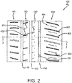
FIG. 2 is a schematic partial view of the tread ofFIG. 1 . -
FIG. 3 is a schematic sectional view taken along "3-3" inFIG. 2 . - As shown in
FIGS. 1 through 3 , atread 100 for use with the present invention preferably has a first circumferentialmain groove 110, a second circumferentialmain groove 120, and a third circumferentialmain groove 130 defining afirst shoulder rib 401, a firstintermediate rib 501, a secondintermediate rib 502, and asecond shoulder rib 402. Eachrib transverse grooves 601 andsipes 602 suitable for tire treads. - The
circumferential grooves - Preferably, the depth of the
circumferential grooves - One or more than one of the circumferential
main grooves third groove 130 inFIGS. 1 and2 ) may have several connectingbridges 701 spaced circumferentially within the main groove. Similar tread structures are disclosed inUS-A-2018/0250989 . As many as thirty or moreconnecting bridges 701 may be included in asingle tread 100. As an example, the connectingbridges 701 may connect the axially outersecond shoulder rib 402 to the axially inner second intermediate rib. - In accordance with the present invention, the
second shoulder rib 402 has a plurality of firstlateral grooves 901 circumferentially alternating with a plurality of secondlateral grooves 902. The first and secondlateral grooves main groove 130. - The first and second
lateral grooves - The radial depth of the first and second
lateral grooves - In one embodiment, the depth of the first and second
lateral grooves - In another embodiment, the depth of the first and second
lateral grooves main groove 130. - The first
lateral grooves 901 preferably terminates equidistantly nearer the third circumferentialmain groove 130 than an equidistant termination of the secondlateral grooves 902. - Further in accordance with the present invention, the
second shoulder rib 402 includes a plurality of double blind, linear,lateral sipes 903 disposed preferably parallel to, and preferably circumferentially midway between, each of the adjacent first and secondlateral grooves 901, 902 (FIGS. 1 and2 ). - The
linear sipes 903 preferably have uniform widths between 0.0 mm and 1.5 mm (e.g., 1.4 mm, 1.3 mm, 1.2 mm, 1.1 mm, 1.0 mm, 0.9 mm, etc.) before attachment to a vehicle and use. - The
linear sipes 903 preferably have uniform radial depths between 2.0 mm and 6.0 mm (e.g., 5.5 mm, 5.0 mm, 4.5 mm, 4.0 mm, 3.5 mm, 3.0 mm, etc.). - The
linear sipes 903 preferably have terminal ends 904 equidistant and farther from the third circumferentialmain groove 130 than the firstlateral grooves 901 and the secondlateral grooves 902. - During cornering of the vehicle, the
linear sipes 903 may close down, with the widths decreasing to 0.0 mm. The sides of thelinear sipes 903 thereby interlock or engage each other to reinforce thesecond shoulder rib 402 during cornering of the attached vehicle. Thelinear sipes 903 may also provide flexibility to thesecond shoulder rib 402 during straight ahead motion of the attached vehicle, with the widths remaining as designed between 0.0 mm and 1.5 mm. The linear sipes further improve cooling and traction of thesecond shoulder rib 402 of thetread 100 during straight ahead motion of the vehicle. - As shown in
FIGS. 1 through 3 , such atread 100 may define an asymmetric tread pattern for performing an advantageous dynamic load transfer in cornering conditions with the outer part of tread getting a higher load and the inside of the tire experiencing reduced load. Therefore, it may be advantageous and much more effective to provide a stiff outside area of atread 100.
Claims (13)
- A tread for a tire, the tread (100) comprising a circumferential groove (130) and a first circumferential shoulder rib (401) and a second circumferential shoulder rib (402), the second circumferential shoulder rib (402) being delimited on the axially inner side of the circumferential shoulder rib (402) by said circumferential groove (130), the circumferential shoulder rib (402) having plurality of first linear lateral grooves (901) circumferentially alternating with a plurality of second linear lateral grooves (902) and having a plurality of double blind lateral sipes (903) disposed circumferentially preferably midway between each adjacent first lateral groove (901) and second lateral groove (902), the first and second lateral grooves (901, 902) extending axially both toward the circumferential groove (130), the first lateral grooves (901) terminating nearer the circumferential groove (130) than the second lateral grooves (902), characterized in that (i) the circumferential width of the first lateral grooves (901) is the same than the circumferential width of the second lateral grooves (902) or is in a range of from 80 to 120 % of the circumferential width of the second lateral grooves (902), and/or in that (ii) the first circumferential shoulder rib (401) comprises a different arrangement of grooves and/or sipes than the second circumferential shoulder rib (402).
- The tread of claim 1 wherein the first lateral grooves (901), the second lateral grooves (902) and the double blind sipes (904) extend in parallel.
- The tread of claim 1 or 2 wherein(i) the axial length of the first lateral grooves (901) is in a range of from 105 to 130 % of the axial length of the second lateral grooves (902); and/or(ii) the axial length of the first lateral grooves (901) is in a range of from 130 to 200 % of the axial length of the double blind sipes (904); and/or(iii) the axial length of the second lateral grooves (901) is in a range of from 110 to 150 % of the axial length of the double blind sipes (904).
- The tread of at least one of the previous claims wherein the circumferential width of the first lateral grooves (901) is in a range of from 150 to 400 %, alternatively 200% to 300%, of the circumferential width of the double blind sipes (904).
- The tread of at least one of the previous claims wherein the first lateral grooves (901) terminate axially 1 mm to 8 mm, preferably 2 mm to 5 mm, nearer the circumferential groove (130) than the second lateral grooves (902).
- The tread of at least one of the previous claims wherein the axial outer end of the first lateral groove (901) has the same axial distance from the circumferential groove (130) than the axial outer end of the second lateral groove (902) or wherein the distance of the axial outer end of the second lateral groove (902) from the circumferential groove (130) is smaller, preferably 1 mm to 3 mm, smaller than the distance of the axial outer end of the first lateral groove (901) from the circumferential groove (130).
- The tread of at least one of the previous claims wherein the double blind sipes (904) are parallel to the first lateral grooves (901) and/or to the second lateral grooves (902).
- The tread of at least one of the previous claims wherein the double blind sipes (904) have terminal ends farther from the circumferential groove (130) than terminations of the first lateral grooves (901) and/or wherein the double blind sipes (904) have terminal ends farther from the circumferential groove (130) than terminations of the second lateral grooves (902).
- The tread of at least one of the previous claims wherein the double blind sipes (904) have widths in a range of from 0.1 mm to 1.5 mm, preferably 0.3 mm to 1 mm, and/or wherein the double blind sipes (904) have radial depths in a range of from 2.0 mm to 6.0 mm, preferably 2.5 to 5.0 mm.
- The tread of at least one of the previous claims wherein the double blind lateral sipes (903) are not disposed circumferentially midway between each adjacent first lateral groove (901) and second lateral groove (902) but the circumferential distance between a respective first lateral groove (901) and the adjacent respective double blind sipe (904) is in a range of from 80% to 120% of the circumferential distance between the respective double blind sipe (904) and the adjacent respective second lateral groove (902).
- The tread of at least one of the previous claims, the tread (100) comprising a first circumferential groove (110), a second circumferential groove (120) and a third circumferential groove (130), the first, second, and third circumferential grooves (110, 120, 130) together defining a first circumferential shoulder rib (401), a first intermediate circumferential rib (501), a second intermediate circumferential rib (502) and a second circumferential shoulder rib (402), wherein the third circumferential groove (130) is the circumferential groove (130) referred to in the previous claims and wherein the second circumferential shoulder rib (402) is the circumferential shoulder rib (402) referred to in the previous claims.
- A tire having the tread in accordance with at least one of the previous claims.
- The tire of claim 12 wherein the circumferential shoulder rib (402) is on the axially outer side of the tire when the tire is mounted on a vehicle in accordance with the tire's specification.
Priority Applications (1)
| Application Number | Priority Date | Filing Date | Title |
|---|---|---|---|
| PL19215349T PL3666551T3 (en) | 2018-12-13 | 2019-12-11 | Tire tread |
Applications Claiming Priority (1)
| Application Number | Priority Date | Filing Date | Title |
|---|---|---|---|
| US16/218,914 US20200189322A1 (en) | 2018-12-13 | 2018-12-13 | Tire tread |
Publications (2)
| Publication Number | Publication Date |
|---|---|
| EP3666551A1 EP3666551A1 (en) | 2020-06-17 |
| EP3666551B1 true EP3666551B1 (en) | 2021-12-01 |
Family
ID=68886906
Family Applications (1)
| Application Number | Title | Priority Date | Filing Date |
|---|---|---|---|
| EP19215349.2A Active EP3666551B1 (en) | 2018-12-13 | 2019-12-11 | Tire tread |
Country Status (3)
| Country | Link |
|---|---|
| US (1) | US20200189322A1 (en) |
| EP (1) | EP3666551B1 (en) |
| PL (1) | PL3666551T3 (en) |
Families Citing this family (4)
| Publication number | Priority date | Publication date | Assignee | Title |
|---|---|---|---|---|
| JP7639368B2 (en) * | 2021-01-28 | 2025-03-05 | 住友ゴム工業株式会社 | tire |
| JP7647443B2 (en) * | 2021-08-24 | 2025-03-18 | 住友ゴム工業株式会社 | tire |
| DE102022210140A1 (en) * | 2022-09-26 | 2024-03-28 | Continental Reifen Deutschland Gmbh | Vehicle tires |
| TWI822616B (en) * | 2023-03-22 | 2023-11-11 | 正新橡膠工業股份有限公司 | Pneumatic tire with improved drainage capability without limiting maneuverability of vehicles |
Family Cites Families (3)
| Publication number | Priority date | Publication date | Assignee | Title |
|---|---|---|---|---|
| US5421387A (en) * | 1992-07-10 | 1995-06-06 | Michelin Recherche Et Technique S.A. | Asymmetrical tire tread |
| JP3247905B2 (en) * | 1992-09-29 | 2002-01-21 | 株式会社ブリヂストン | Pneumatic tire for motorcycle |
| US10639941B2 (en) | 2017-03-06 | 2020-05-05 | The Goodyear Tire & Rubber Company | Tire tread with bridges |
-
2018
- 2018-12-13 US US16/218,914 patent/US20200189322A1/en not_active Abandoned
-
2019
- 2019-12-11 PL PL19215349T patent/PL3666551T3/en unknown
- 2019-12-11 EP EP19215349.2A patent/EP3666551B1/en active Active
Also Published As
| Publication number | Publication date |
|---|---|
| US20200189322A1 (en) | 2020-06-18 |
| EP3666551A1 (en) | 2020-06-17 |
| PL3666551T3 (en) | 2022-02-21 |
Similar Documents
| Publication | Publication Date | Title |
|---|---|---|
| EP3260308B1 (en) | Tire | |
| EP3178668B1 (en) | Pneumatic tire | |
| EP3095623B1 (en) | Pneumatic tire | |
| EP3025875B1 (en) | Pneumatic tire | |
| EP3093163B1 (en) | Pneumatic tire | |
| EP3307557B1 (en) | Tyre tread | |
| EP3666551B1 (en) | Tire tread | |
| US10814678B2 (en) | Tire | |
| EP2444257A1 (en) | Heavy duty tire | |
| EP2881266B1 (en) | Pneumatic tire | |
| US11383559B2 (en) | Pneumatic tire | |
| CN109130707B (en) | Tyre for vehicle wheels | |
| US11148472B2 (en) | Tyre | |
| US20190160880A1 (en) | Tire | |
| CN110936770B (en) | Tyre | |
| EP2881267B1 (en) | A tire comprising a tread with asymmetric groove profiles | |
| EP3670209B1 (en) | Tread for a pneumatic tire | |
| EP3744537B1 (en) | Tire | |
| CN106427402B (en) | Pneumatic tire | |
| EP3970994B1 (en) | Tire tread and tire with such a tread | |
| EP3269566B1 (en) | Tire | |
| EP3744535B1 (en) | Tire | |
| EP3549793B1 (en) | Tyre | |
| US11691458B2 (en) | Tire comprising a tread having grooves with undercut side faces and reinforcing elements | |
| EP3970993B1 (en) | Tire tread and tire comprising a stabilizer structure |
Legal Events
| Date | Code | Title | Description |
|---|---|---|---|
| PUAI | Public reference made under article 153(3) epc to a published international application that has entered the european phase |
Free format text: ORIGINAL CODE: 0009012 |
|
| STAA | Information on the status of an ep patent application or granted ep patent |
Free format text: STATUS: THE APPLICATION HAS BEEN PUBLISHED |
|
| AK | Designated contracting states |
Kind code of ref document: A1 Designated state(s): AL AT BE BG CH CY CZ DE DK EE ES FI FR GB GR HR HU IE IS IT LI LT LU LV MC MK MT NL NO PL PT RO RS SE SI SK SM TR |
|
| AX | Request for extension of the european patent |
Extension state: BA ME |
|
| STAA | Information on the status of an ep patent application or granted ep patent |
Free format text: STATUS: REQUEST FOR EXAMINATION WAS MADE |
|
| 17P | Request for examination filed |
Effective date: 20201217 |
|
| RBV | Designated contracting states (corrected) |
Designated state(s): AL AT BE BG CH CY CZ DE DK EE ES FI FR GB GR HR HU IE IS IT LI LT LU LV MC MK MT NL NO PL PT RO RS SE SI SK SM TR |
|
| RIC1 | Information provided on ipc code assigned before grant |
Ipc: B60C 11/03 20060101AFI20210421BHEP Ipc: B60C 11/12 20060101ALN20210421BHEP |
|
| RIC1 | Information provided on ipc code assigned before grant |
Ipc: B60C 11/03 20060101AFI20210507BHEP Ipc: B60C 11/12 20060101ALN20210507BHEP |
|
| GRAP | Despatch of communication of intention to grant a patent |
Free format text: ORIGINAL CODE: EPIDOSNIGR1 |
|
| STAA | Information on the status of an ep patent application or granted ep patent |
Free format text: STATUS: GRANT OF PATENT IS INTENDED |
|
| RIC1 | Information provided on ipc code assigned before grant |
Ipc: B60C 11/03 20060101AFI20210521BHEP Ipc: B60C 11/12 20060101ALN20210521BHEP |
|
| INTG | Intention to grant announced |
Effective date: 20210624 |
|
| GRAS | Grant fee paid |
Free format text: ORIGINAL CODE: EPIDOSNIGR3 |
|
| GRAA | (expected) grant |
Free format text: ORIGINAL CODE: 0009210 |
|
| STAA | Information on the status of an ep patent application or granted ep patent |
Free format text: STATUS: THE PATENT HAS BEEN GRANTED |
|
| AK | Designated contracting states |
Kind code of ref document: B1 Designated state(s): AL AT BE BG CH CY CZ DE DK EE ES FI FR GB GR HR HU IE IS IT LI LT LU LV MC MK MT NL NO PL PT RO RS SE SI SK SM TR |
|
| REG | Reference to a national code |
Ref country code: GB Ref legal event code: FG4D |
|
| REG | Reference to a national code |
Ref country code: AT Ref legal event code: REF Ref document number: 1451414 Country of ref document: AT Kind code of ref document: T Effective date: 20211215 Ref country code: CH Ref legal event code: EP |
|
| REG | Reference to a national code |
Ref country code: IE Ref legal event code: FG4D |
|
| REG | Reference to a national code |
Ref country code: DE Ref legal event code: R096 Ref document number: 602019009732 Country of ref document: DE |
|
| REG | Reference to a national code |
Ref country code: LT Ref legal event code: MG9D |
|
| REG | Reference to a national code |
Ref country code: AT Ref legal event code: MK05 Ref document number: 1451414 Country of ref document: AT Kind code of ref document: T Effective date: 20211201 |
|
| PG25 | Lapsed in a contracting state [announced via postgrant information from national office to epo] |
Ref country code: RS Free format text: LAPSE BECAUSE OF FAILURE TO SUBMIT A TRANSLATION OF THE DESCRIPTION OR TO PAY THE FEE WITHIN THE PRESCRIBED TIME-LIMIT Effective date: 20211201 Ref country code: LT Free format text: LAPSE BECAUSE OF FAILURE TO SUBMIT A TRANSLATION OF THE DESCRIPTION OR TO PAY THE FEE WITHIN THE PRESCRIBED TIME-LIMIT Effective date: 20211201 Ref country code: FI Free format text: LAPSE BECAUSE OF FAILURE TO SUBMIT A TRANSLATION OF THE DESCRIPTION OR TO PAY THE FEE WITHIN THE PRESCRIBED TIME-LIMIT Effective date: 20211201 Ref country code: BG Free format text: LAPSE BECAUSE OF FAILURE TO SUBMIT A TRANSLATION OF THE DESCRIPTION OR TO PAY THE FEE WITHIN THE PRESCRIBED TIME-LIMIT Effective date: 20220301 Ref country code: AT Free format text: LAPSE BECAUSE OF FAILURE TO SUBMIT A TRANSLATION OF THE DESCRIPTION OR TO PAY THE FEE WITHIN THE PRESCRIBED TIME-LIMIT Effective date: 20211201 |
|
| PG25 | Lapsed in a contracting state [announced via postgrant information from national office to epo] |
Ref country code: SE Free format text: LAPSE BECAUSE OF FAILURE TO SUBMIT A TRANSLATION OF THE DESCRIPTION OR TO PAY THE FEE WITHIN THE PRESCRIBED TIME-LIMIT Effective date: 20211201 Ref country code: NO Free format text: LAPSE BECAUSE OF FAILURE TO SUBMIT A TRANSLATION OF THE DESCRIPTION OR TO PAY THE FEE WITHIN THE PRESCRIBED TIME-LIMIT Effective date: 20220301 Ref country code: LV Free format text: LAPSE BECAUSE OF FAILURE TO SUBMIT A TRANSLATION OF THE DESCRIPTION OR TO PAY THE FEE WITHIN THE PRESCRIBED TIME-LIMIT Effective date: 20211201 Ref country code: HR Free format text: LAPSE BECAUSE OF FAILURE TO SUBMIT A TRANSLATION OF THE DESCRIPTION OR TO PAY THE FEE WITHIN THE PRESCRIBED TIME-LIMIT Effective date: 20211201 Ref country code: GR Free format text: LAPSE BECAUSE OF FAILURE TO SUBMIT A TRANSLATION OF THE DESCRIPTION OR TO PAY THE FEE WITHIN THE PRESCRIBED TIME-LIMIT Effective date: 20220302 Ref country code: ES Free format text: LAPSE BECAUSE OF FAILURE TO SUBMIT A TRANSLATION OF THE DESCRIPTION OR TO PAY THE FEE WITHIN THE PRESCRIBED TIME-LIMIT Effective date: 20211201 |
|
| PG25 | Lapsed in a contracting state [announced via postgrant information from national office to epo] |
Ref country code: NL Free format text: LAPSE BECAUSE OF FAILURE TO SUBMIT A TRANSLATION OF THE DESCRIPTION OR TO PAY THE FEE WITHIN THE PRESCRIBED TIME-LIMIT Effective date: 20211201 |
|
| PG25 | Lapsed in a contracting state [announced via postgrant information from national office to epo] |
Ref country code: SM Free format text: LAPSE BECAUSE OF FAILURE TO SUBMIT A TRANSLATION OF THE DESCRIPTION OR TO PAY THE FEE WITHIN THE PRESCRIBED TIME-LIMIT Effective date: 20211201 Ref country code: SK Free format text: LAPSE BECAUSE OF FAILURE TO SUBMIT A TRANSLATION OF THE DESCRIPTION OR TO PAY THE FEE WITHIN THE PRESCRIBED TIME-LIMIT Effective date: 20211201 Ref country code: RO Free format text: LAPSE BECAUSE OF FAILURE TO SUBMIT A TRANSLATION OF THE DESCRIPTION OR TO PAY THE FEE WITHIN THE PRESCRIBED TIME-LIMIT Effective date: 20211201 Ref country code: PT Free format text: LAPSE BECAUSE OF FAILURE TO SUBMIT A TRANSLATION OF THE DESCRIPTION OR TO PAY THE FEE WITHIN THE PRESCRIBED TIME-LIMIT Effective date: 20220401 Ref country code: EE Free format text: LAPSE BECAUSE OF FAILURE TO SUBMIT A TRANSLATION OF THE DESCRIPTION OR TO PAY THE FEE WITHIN THE PRESCRIBED TIME-LIMIT Effective date: 20211201 Ref country code: CZ Free format text: LAPSE BECAUSE OF FAILURE TO SUBMIT A TRANSLATION OF THE DESCRIPTION OR TO PAY THE FEE WITHIN THE PRESCRIBED TIME-LIMIT Effective date: 20211201 |
|
| PG25 | Lapsed in a contracting state [announced via postgrant information from national office to epo] |
Ref country code: MC Free format text: LAPSE BECAUSE OF FAILURE TO SUBMIT A TRANSLATION OF THE DESCRIPTION OR TO PAY THE FEE WITHIN THE PRESCRIBED TIME-LIMIT Effective date: 20211201 |
|
| REG | Reference to a national code |
Ref country code: DE Ref legal event code: R097 Ref document number: 602019009732 Country of ref document: DE |
|
| REG | Reference to a national code |
Ref country code: BE Ref legal event code: MM Effective date: 20211231 |
|
| PG25 | Lapsed in a contracting state [announced via postgrant information from national office to epo] |
Ref country code: IS Free format text: LAPSE BECAUSE OF FAILURE TO SUBMIT A TRANSLATION OF THE DESCRIPTION OR TO PAY THE FEE WITHIN THE PRESCRIBED TIME-LIMIT Effective date: 20220401 |
|
| PLBE | No opposition filed within time limit |
Free format text: ORIGINAL CODE: 0009261 |
|
| STAA | Information on the status of an ep patent application or granted ep patent |
Free format text: STATUS: NO OPPOSITION FILED WITHIN TIME LIMIT |
|
| PG25 | Lapsed in a contracting state [announced via postgrant information from national office to epo] |
Ref country code: LU Free format text: LAPSE BECAUSE OF NON-PAYMENT OF DUE FEES Effective date: 20211211 Ref country code: IE Free format text: LAPSE BECAUSE OF NON-PAYMENT OF DUE FEES Effective date: 20211211 Ref country code: DK Free format text: LAPSE BECAUSE OF FAILURE TO SUBMIT A TRANSLATION OF THE DESCRIPTION OR TO PAY THE FEE WITHIN THE PRESCRIBED TIME-LIMIT Effective date: 20211201 Ref country code: AL Free format text: LAPSE BECAUSE OF FAILURE TO SUBMIT A TRANSLATION OF THE DESCRIPTION OR TO PAY THE FEE WITHIN THE PRESCRIBED TIME-LIMIT Effective date: 20211201 |
|
| 26N | No opposition filed |
Effective date: 20220902 |
|
| PG25 | Lapsed in a contracting state [announced via postgrant information from national office to epo] |
Ref country code: SI Free format text: LAPSE BECAUSE OF FAILURE TO SUBMIT A TRANSLATION OF THE DESCRIPTION OR TO PAY THE FEE WITHIN THE PRESCRIBED TIME-LIMIT Effective date: 20211201 Ref country code: BE Free format text: LAPSE BECAUSE OF NON-PAYMENT OF DUE FEES Effective date: 20211231 |
|
| PG25 | Lapsed in a contracting state [announced via postgrant information from national office to epo] |
Ref country code: CY Free format text: LAPSE BECAUSE OF FAILURE TO SUBMIT A TRANSLATION OF THE DESCRIPTION OR TO PAY THE FEE WITHIN THE PRESCRIBED TIME-LIMIT Effective date: 20211201 |
|
| PG25 | Lapsed in a contracting state [announced via postgrant information from national office to epo] |
Ref country code: HU Free format text: LAPSE BECAUSE OF FAILURE TO SUBMIT A TRANSLATION OF THE DESCRIPTION OR TO PAY THE FEE WITHIN THE PRESCRIBED TIME-LIMIT; INVALID AB INITIO Effective date: 20191211 |
|
| REG | Reference to a national code |
Ref country code: CH Ref legal event code: PL |
|
| PG25 | Lapsed in a contracting state [announced via postgrant information from national office to epo] |
Ref country code: LI Free format text: LAPSE BECAUSE OF NON-PAYMENT OF DUE FEES Effective date: 20221231 Ref country code: CH Free format text: LAPSE BECAUSE OF NON-PAYMENT OF DUE FEES Effective date: 20221231 |
|
| PGFP | Annual fee paid to national office [announced via postgrant information from national office to epo] |
Ref country code: GB Payment date: 20231019 Year of fee payment: 5 |
|
| PG25 | Lapsed in a contracting state [announced via postgrant information from national office to epo] |
Ref country code: MK Free format text: LAPSE BECAUSE OF FAILURE TO SUBMIT A TRANSLATION OF THE DESCRIPTION OR TO PAY THE FEE WITHIN THE PRESCRIBED TIME-LIMIT Effective date: 20211201 |
|
| PG25 | Lapsed in a contracting state [announced via postgrant information from national office to epo] |
Ref country code: TR Free format text: LAPSE BECAUSE OF FAILURE TO SUBMIT A TRANSLATION OF THE DESCRIPTION OR TO PAY THE FEE WITHIN THE PRESCRIBED TIME-LIMIT Effective date: 20211201 |
|
| PG25 | Lapsed in a contracting state [announced via postgrant information from national office to epo] |
Ref country code: MT Free format text: LAPSE BECAUSE OF FAILURE TO SUBMIT A TRANSLATION OF THE DESCRIPTION OR TO PAY THE FEE WITHIN THE PRESCRIBED TIME-LIMIT Effective date: 20211201 |
|
| GBPC | Gb: european patent ceased through non-payment of renewal fee |
Effective date: 20241211 |
|
| PG25 | Lapsed in a contracting state [announced via postgrant information from national office to epo] |
Ref country code: GB Free format text: LAPSE BECAUSE OF NON-PAYMENT OF DUE FEES Effective date: 20241211 |
|
| PGFP | Annual fee paid to national office [announced via postgrant information from national office to epo] |
Ref country code: DE Payment date: 20251126 Year of fee payment: 7 |
|
| PGFP | Annual fee paid to national office [announced via postgrant information from national office to epo] |
Ref country code: IT Payment date: 20251119 Year of fee payment: 7 |
|
| PGFP | Annual fee paid to national office [announced via postgrant information from national office to epo] |
Ref country code: FR Payment date: 20251120 Year of fee payment: 7 |
|
| PGFP | Annual fee paid to national office [announced via postgrant information from national office to epo] |
Ref country code: PL Payment date: 20251128 Year of fee payment: 7 |