EP3666536A1 - Printer and printer display device - Google Patents
Printer and printer display device Download PDFInfo
- Publication number
- EP3666536A1 EP3666536A1 EP19215207.2A EP19215207A EP3666536A1 EP 3666536 A1 EP3666536 A1 EP 3666536A1 EP 19215207 A EP19215207 A EP 19215207A EP 3666536 A1 EP3666536 A1 EP 3666536A1
- Authority
- EP
- European Patent Office
- Prior art keywords
- printer
- display
- main body
- display device
- display portion
- Prior art date
- Legal status (The legal status is an assumption and is not a legal conclusion. Google has not performed a legal analysis and makes no representation as to the accuracy of the status listed.)
- Granted
Links
Images







Classifications
-
- B—PERFORMING OPERATIONS; TRANSPORTING
- B41—PRINTING; LINING MACHINES; TYPEWRITERS; STAMPS
- B41J—TYPEWRITERS; SELECTIVE PRINTING MECHANISMS, i.e. MECHANISMS PRINTING OTHERWISE THAN FROM A FORME; CORRECTION OF TYPOGRAPHICAL ERRORS
- B41J29/00—Details of, or accessories for, typewriters or selective printing mechanisms not otherwise provided for
- B41J29/02—Framework
-
- B—PERFORMING OPERATIONS; TRANSPORTING
- B41—PRINTING; LINING MACHINES; TYPEWRITERS; STAMPS
- B41J—TYPEWRITERS; SELECTIVE PRINTING MECHANISMS, i.e. MECHANISMS PRINTING OTHERWISE THAN FROM A FORME; CORRECTION OF TYPOGRAPHICAL ERRORS
- B41J15/00—Devices or arrangements of selective printing mechanisms, e.g. ink-jet printers or thermal printers, specially adapted for supporting or handling copy material in continuous form, e.g. webs
- B41J15/04—Supporting, feeding, or guiding devices; Mountings for web rolls or spindles
- B41J15/042—Supporting, feeding, or guiding devices; Mountings for web rolls or spindles for loading rolled-up continuous copy material into printers, e.g. for replacing a used-up paper roll; Point-of-sale printers with openable casings allowing access to the rolled-up continuous copy material
-
- B—PERFORMING OPERATIONS; TRANSPORTING
- B41—PRINTING; LINING MACHINES; TYPEWRITERS; STAMPS
- B41J—TYPEWRITERS; SELECTIVE PRINTING MECHANISMS, i.e. MECHANISMS PRINTING OTHERWISE THAN FROM A FORME; CORRECTION OF TYPOGRAPHICAL ERRORS
- B41J29/00—Details of, or accessories for, typewriters or selective printing mechanisms not otherwise provided for
- B41J29/12—Guards, shields or dust excluders
- B41J29/13—Cases or covers
-
- B—PERFORMING OPERATIONS; TRANSPORTING
- B41—PRINTING; LINING MACHINES; TYPEWRITERS; STAMPS
- B41J—TYPEWRITERS; SELECTIVE PRINTING MECHANISMS, i.e. MECHANISMS PRINTING OTHERWISE THAN FROM A FORME; CORRECTION OF TYPOGRAPHICAL ERRORS
- B41J3/00—Typewriters or selective printing or marking mechanisms characterised by the purpose for which they are constructed
- B41J3/44—Typewriters or selective printing mechanisms having dual functions or combined with, or coupled to, apparatus performing other functions
- B41J3/46—Printing mechanisms combined with apparatus providing a visual indication
-
- F—MECHANICAL ENGINEERING; LIGHTING; HEATING; WEAPONS; BLASTING
- F16—ENGINEERING ELEMENTS AND UNITS; GENERAL MEASURES FOR PRODUCING AND MAINTAINING EFFECTIVE FUNCTIONING OF MACHINES OR INSTALLATIONS; THERMAL INSULATION IN GENERAL
- F16M—FRAMES, CASINGS OR BEDS OF ENGINES, MACHINES OR APPARATUS, NOT SPECIFIC TO ENGINES, MACHINES OR APPARATUS PROVIDED FOR ELSEWHERE; STANDS; SUPPORTS
- F16M11/00—Stands or trestles as supports for apparatus or articles placed thereon ; Stands for scientific apparatus such as gravitational force meters
- F16M11/02—Heads
- F16M11/04—Means for attachment of apparatus; Means allowing adjustment of the apparatus relatively to the stand
- F16M11/041—Allowing quick release of the apparatus
-
- F—MECHANICAL ENGINEERING; LIGHTING; HEATING; WEAPONS; BLASTING
- F16—ENGINEERING ELEMENTS AND UNITS; GENERAL MEASURES FOR PRODUCING AND MAINTAINING EFFECTIVE FUNCTIONING OF MACHINES OR INSTALLATIONS; THERMAL INSULATION IN GENERAL
- F16M—FRAMES, CASINGS OR BEDS OF ENGINES, MACHINES OR APPARATUS, NOT SPECIFIC TO ENGINES, MACHINES OR APPARATUS PROVIDED FOR ELSEWHERE; STANDS; SUPPORTS
- F16M11/00—Stands or trestles as supports for apparatus or articles placed thereon ; Stands for scientific apparatus such as gravitational force meters
- F16M11/02—Heads
- F16M11/04—Means for attachment of apparatus; Means allowing adjustment of the apparatus relatively to the stand
- F16M11/06—Means for attachment of apparatus; Means allowing adjustment of the apparatus relatively to the stand allowing pivoting
- F16M11/10—Means for attachment of apparatus; Means allowing adjustment of the apparatus relatively to the stand allowing pivoting around a horizontal axis
-
- F—MECHANICAL ENGINEERING; LIGHTING; HEATING; WEAPONS; BLASTING
- F16—ENGINEERING ELEMENTS AND UNITS; GENERAL MEASURES FOR PRODUCING AND MAINTAINING EFFECTIVE FUNCTIONING OF MACHINES OR INSTALLATIONS; THERMAL INSULATION IN GENERAL
- F16M—FRAMES, CASINGS OR BEDS OF ENGINES, MACHINES OR APPARATUS, NOT SPECIFIC TO ENGINES, MACHINES OR APPARATUS PROVIDED FOR ELSEWHERE; STANDS; SUPPORTS
- F16M11/00—Stands or trestles as supports for apparatus or articles placed thereon ; Stands for scientific apparatus such as gravitational force meters
- F16M11/20—Undercarriages with or without wheels
- F16M11/2007—Undercarriages with or without wheels comprising means allowing pivoting adjustment
- F16M11/2014—Undercarriages with or without wheels comprising means allowing pivoting adjustment around a vertical axis
-
- F—MECHANICAL ENGINEERING; LIGHTING; HEATING; WEAPONS; BLASTING
- F16—ENGINEERING ELEMENTS AND UNITS; GENERAL MEASURES FOR PRODUCING AND MAINTAINING EFFECTIVE FUNCTIONING OF MACHINES OR INSTALLATIONS; THERMAL INSULATION IN GENERAL
- F16M—FRAMES, CASINGS OR BEDS OF ENGINES, MACHINES OR APPARATUS, NOT SPECIFIC TO ENGINES, MACHINES OR APPARATUS PROVIDED FOR ELSEWHERE; STANDS; SUPPORTS
- F16M13/00—Other supports for positioning apparatus or articles; Means for steadying hand-held apparatus or articles
- F16M13/005—Other supports for positioning apparatus or articles; Means for steadying hand-held apparatus or articles integral with the apparatus or articles to be supported
-
- F—MECHANICAL ENGINEERING; LIGHTING; HEATING; WEAPONS; BLASTING
- F16—ENGINEERING ELEMENTS AND UNITS; GENERAL MEASURES FOR PRODUCING AND MAINTAINING EFFECTIVE FUNCTIONING OF MACHINES OR INSTALLATIONS; THERMAL INSULATION IN GENERAL
- F16M—FRAMES, CASINGS OR BEDS OF ENGINES, MACHINES OR APPARATUS, NOT SPECIFIC TO ENGINES, MACHINES OR APPARATUS PROVIDED FOR ELSEWHERE; STANDS; SUPPORTS
- F16M13/00—Other supports for positioning apparatus or articles; Means for steadying hand-held apparatus or articles
- F16M13/02—Other supports for positioning apparatus or articles; Means for steadying hand-held apparatus or articles for supporting on, or attaching to, an object, e.g. tree, gate, window-frame, cycle
-
- G—PHYSICS
- G07—CHECKING-DEVICES
- G07G—REGISTERING THE RECEIPT OF CASH, VALUABLES, OR TOKENS
- G07G5/00—Receipt-giving machines
-
- G—PHYSICS
- G09—EDUCATION; CRYPTOGRAPHY; DISPLAY; ADVERTISING; SEALS
- G09G—ARRANGEMENTS OR CIRCUITS FOR CONTROL OF INDICATING DEVICES USING STATIC MEANS TO PRESENT VARIABLE INFORMATION
- G09G5/00—Control arrangements or circuits for visual indicators common to cathode-ray tube indicators and other visual indicators
- G09G5/003—Details of a display terminal, the details relating to the control arrangement of the display terminal and to the interfaces thereto
-
- H—ELECTRICITY
- H04—ELECTRIC COMMUNICATION TECHNIQUE
- H04N—PICTORIAL COMMUNICATION, e.g. TELEVISION
- H04N1/00—Scanning, transmission or reproduction of documents or the like, e.g. facsimile transmission; Details thereof
- H04N1/00519—Constructional details not otherwise provided for, e.g. housings, covers
- H04N1/00543—Allowing easy access, e.g. for maintenance or in case of paper jam
- H04N1/00546—Allowing easy access, e.g. for maintenance or in case of paper jam using a side opening
Definitions
- the orientation of the display portion 51 is described in more detail.
- the rotation axis M1 extends along the right-and-left direction L3, and hence the display portion main body 50 can be displaced relative to the fixing portion 40 while the display portion main body 50 is rotated upward or downward about the rotation axis M1. Accordingly, the angle can be adjusted so that the display portion 51 is oriented toward the upper side while the display portion main body 50 is rotated so as to be opened to the upper side from the first position P1 illustrated in FIG. 8 to FIG. 10 .
- the display portion main body 50 can be set to a position at which the display portion main body 50 is rotated by 45° from the first position P1. With this, for example, the store staff can satisfactorily visually recognize the display portion 51 by directing a line of sight downward in a standing posture. Thus, the visibility of the printer display device 6 can be further enhanced.
Landscapes
- Engineering & Computer Science (AREA)
- General Engineering & Computer Science (AREA)
- Mechanical Engineering (AREA)
- Physics & Mathematics (AREA)
- General Physics & Mathematics (AREA)
- Computer Hardware Design (AREA)
- Theoretical Computer Science (AREA)
- Multimedia (AREA)
- Signal Processing (AREA)
- Accessory Devices And Overall Control Thereof (AREA)
Abstract
Description
- The present invention relates to a printer and a printer display device.
- As an apparatus for, for example, inputting sales, receiving or paying money, or issuing a receipt in various kinds of stores and the like, a POS system configured to manage a point-of-sale system (POS) has hitherto been adopted. This type of POS system includes, for example, a POS terminal, a printer, a display device such as a liquid crystal display, and peripheral equipment such as a cash drawer.
- As the printer forming the POS system, various types have been known. For example, a printer connected to a display device through a connection cable or the like has been known. There has hitherto been known, for example, a printer stand that includes a support portion configured to removably support a printer (thermal printer) on a front surface side and removably support a display device on a back surface side. This printer stand can mainly exhibit two functions: a printer support function of supporting the printer in a posture different from an installation posture (for example, a horizontal posture) of the independent printer; and an advertising function as an advertising medium or the like for displaying various kinds of information through the display device. As another printer, there has also been known, for example, a printer connected to a self-standing display device through a connection cable or the like.
- However, in the case of the above-mentioned related-art printer stand, the display device is fixed to the back surface side of the support portion, and hence the angle (viewing angle) at which the display device can be visually recognized is liable to be limited. Therefore, the direction in which the display device is visually recognized is limited in accordance with the posture of the printer stand. As a result, after the printer stand is installed, an orientation of the display device cannot be easily changed, and it is difficult to effectively display various kinds of information. Further, the printer and the display device are supported by the printer stand, and hence it is required to secure installation space of the printer stand itself having a large size in order to install the printer and the display device. Therefore, it is required to secure large installation space, and an installation position is liable to be limited. Thus, there is room for improvement.
- Further, the printer is supported on the front surface side of the support portion, and the display device is supported on the back surface side of the support portion. Therefore, it is difficult, for example, for a person who receives printed matter such as a receipt printed by the printer to visually recognize various kinds of information displayed on the display device. Therefore, the related-art printer utilizing the printer stand is not adaptable to such a method of use and is inconvenient. Further, the printer stand configured to support the printer and the display device is required in addition to the printer and the display device, and hence the number of components is increased accordingly, which is liable to cause an increase in cost.
- Further, in the case of the related-art printer connected to the self-standing display device, unlike the case of utilizing the above-mentioned printer stand, the display device can be installed separately from the printer. Therefore, visibility can be sufficiently ensured. However, it is required to secure each installation position of the printer and the display device, and hence large installation space is also required. Further, the display device itself may fall down, with the result that there is an increased risk leading to a defect, and the reliability of installation is not sufficient.
- In view of the above-mentioned circumstances, in this type of technical field, there has been a demand for a printer and a printer display device in which high visibility can be ensured, and space and cost can be saved.
- According to one embodiment of the present invention, there is provided a printer, including: a printer housing, which includes a plurality of outer surfaces including a bottom surface opposed to an installation surface, and has a recording paper receiving portion configured to receive recording paper through an opening portion; a printer cover, which is coupled to the printer housing, and is configured to openably cover the opening portion; a printer display device, which is removably mounted to the outer surface, of the plurality of outer surfaces, other than the bottom surface, and is configured to display predetermined information; and a connection cable, which is connected between the printer housing and the printer display device, and is configured to communicate at least data related to the predetermined information, the printer display device including: a fixing portion separably mounted to the outer surface; a display portion main body having a display portion configured to display the predetermined information provided thereon; and a hinge portion configured to couple the fixing portion and the display portion main body to each other so that the display portion main body is displaced relative to the fixing portion.
- Preferably, the printer housing includes, as the plurality of outer surfaces, at least a front surface and a back surface opposed to each other, wherein the printer cover is provided on the front surface, and wherein the printer display device is separably mounted to the back surface.
- Preferably, the hinge portion has a rotation axis extending in parallel to each of the installation surface and the outer surface to which the printer display device is mounted, and the display portion main body is coupled to the fixing portion so as to be rotated about the rotation axis through intermediation of the hinge portion.
- Preferably, the printer housing further includes, as the plurality of outer surfaces, a top surface opposed to the bottom surface, and the display portion main body is configured to be displaced by rotation about the rotation axis between a first position at which the display portion main body is overlapped with the fixing portion and a second position at which the display portion is positioned above the top surface.
- Preferably, the display portion main body is configured to be rotated within a rotation angle range of 180° about the rotation axis from the first position, wherein the second position is set to be a position at which the display portion main body is rotated by 135° or more about the rotation axis from the first position.
- Preferably, the fixing portion includes: a first base portion separably mounted to the outer surface; a second base portion having the display portion main body coupled thereto through intermediation of the hinge portion; and a coupling member configured to couple the first base portion and the second base portion to each other so that the second base portion is displaced relative to the first base portion through intermediation of at least one auxiliary hinge portion.
- According to one embodiment of the present invention, there is provided a printer display device which is separably mounted to a printer, and has at least data related to predetermined information communicated thereto through a connection cable connected between a printer housing and the printer display device, the printer including: the printer housing, which includes a plurality of outer surfaces including a bottom surface opposed to an installation surface, and has a recording paper receiving portion configured to receive recording paper through an opening portion; and a printer cover, which is coupled to the printer housing, and is configured to openably cover the opening portion, the printer display device including: a fixing portion separably mounted to the outer surface, of the plurality of outer surfaces, other than the bottom surface; a display portion main body having a display portion configured to display the predetermined information provided thereon; and a hinge portion configured to couple the fixing portion and the display portion main body to each other so that the display portion main body is displaced relative to the fixing portion.
- Embodiments of the present invention will now be described by way of further example only and with reference to the accompanying drawings, in which:
-
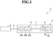
FIG. 1 is a block diagram of a POS system including a thermal printer (printer) according to a first embodiment of the present invention. -
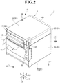
FIG. 2 is a perspective view of the thermal printer illustrated inFIG. 1 when viewed from a front surface side. -
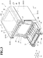
FIG. 3 is a perspective view of the thermal printer in a state in which a printer cover is opened from the state illustrated inFIG. 2 . -
FIG. 4 is a perspective view of the thermal printer illustrated inFIG. 2 when viewed from a back surface side. -
FIG. 5 is a side view of the thermal printer illustrated inFIG. 4 . -
FIG. 6 is a perspective view of the thermal printer illustrated inFIG. 4 when viewed from a bottom surface side. -
FIG. 7 is a perspective view of the thermal printer in a state in which a printer display device is removed from the state illustrated inFIG. 4 . -
FIG. 8 is a perspective view of the thermal printer in a state in which a display portion main body illustrated inFIG. 4 is arranged so as to be overlapped with a fixing portion. -
FIG. 9 is a side view of the thermal printer illustrated inFIG. 8 . -
FIG. 10 is a perspective view of the thermal printer illustrated inFIG. 8 when viewed from the bottom surface side. -
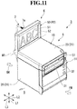
FIG. 11 is a perspective view of the thermal printer in a state in which the display portion main body illustrated inFIG. 8 is rotated upward by 180° with respect to the fixing portion. -
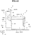
FIG. 12 is a side view of the thermal printer illustrated inFIG. 11 . -
FIG. 13 is a perspective view of the thermal printer illustrated inFIG. 11 when viewed from the bottom surface side. -
FIG. 14 is a perspective view of the printer display device in a state in which the printer display device removed inFIG. 7 is used under a condition of being fixed to a wall. -
FIG. 15 is a perspective view of the printer display device in a state in which the printer display device removed inFIG. 7 is used under a condition of being installed on an installation surface. -
FIG. 16 is a perspective view of the thermal printer in a state in which the printer display device removed inFIG. 7 is used under a condition of being installed on a top surface of a casing. -
FIG. 17 is a perspective view of the thermal printer in a state in which the printer display device removed inFIG. 7 is used under a condition of being installed on the top surface of the casing. -
FIG. 18 is a perspective view of a thermal printer according to a second embodiment of the present invention when viewed from a back surface side. -
FIG. 19 is a side view of the thermal printer illustrated inFIG. 18 . -
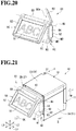
FIG. 20 is a perspective view of a printer display device illustrated inFIG. 18 . -
FIG. 21 is a perspective view of the thermal printer in a state in which the printer display device is rotated upward by 45° from the state illustrated inFIG. 18 . -
FIG. 22 is a side view of the thermal printer illustrated inFIG. 21 . -
FIG. 23 is a perspective view of the thermal printer in a state in which the printer display device is rotated by 45° in an in-plane direction parallel to an installation surface from the state illustrated inFIG. 21 . -
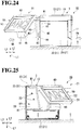
FIG. 24 is a side view of the thermal printer illustrated inFIG. 23 . -
FIG. 25 is a rear view of the thermal printer illustrated inFIG. 23 when viewed from the back surface side. -
FIG. 26 is a top view of the thermal printer illustrated inFIG. 23 . -
FIG. 27 is a perspective view of the thermal printer in a state in which the printer display device is further rotated in the in-plane direction parallel to the installation surface from the state illustrated inFIG. 23 , to thereby direct a display portion to a front side. -
FIG. 28 is a rear view of the thermal printer illustrated inFIG. 27 when viewed from the back surface side. -
FIG. 29 is a perspective view of a modification example of the thermal printer according to the present invention in a state in which the printer display device is removed. -
FIG. 30 is a perspective view of another modification example of the thermal printer according to the present invention in a state in which the printer display device is removed. - Now, a first embodiment of the present invention is described with reference to the drawings. In the first embodiment, description is given of an example of a thermal printer to be used in a POS system.
- As illustrated in
FIG. 1 , a POS system 1 is a system configured to add up sales results of articles and the like on a single item basis, and mainly includes aninformation processing device 2 and athermal printer 3. The POS system 1 is installed in various kinds of stores such as a convenience store, a retail store, and a restaurant. In addition, the POS system 1 is configured to display, to customers, various kinds of information including payment information such as names and prices of articles purchased by the customers at a store. The POS system 1 may further include another peripheral equipment as well as theinformation processing device 2 and thethermal printer 3. - Examples of the
information processing device 2 include a desktop type personal computer and a tablet type personal computer, but are not limited thereto. Theinformation processing device 2 and thethermal printer 3 are directly connected to each other through aconnection cable 4 such as a universal serial bus (USB) cable (wired connection). However, the mode of connection is not limited thereto. For example, theinformation processing device 2 and thethermal printer 3 may be connected to each other by wireless connection through radio communication means or the like, or may be connected to each other through a network. - As illustrated in
FIG. 1 to FIG. 4 , thethermal printer 3 is configured to perform printing on roll-shaped recording paper (heat sensitive paper) P, and the recording paper P can be used as, for example, a ticket or a receipt. Thethermal printer 3 mainly includes a printermain body 5, aprinter display device 6, and a USB cable (connection cable according to the present invention) 7. The printermain body 5 is configured to print various kinds of information on the recording paper P. Theprinter display device 6 is configured to display various kinds of information. TheUSB cable 7 is connected between the printermain body 5 and theprinter display device 6, and is configured to communicate at least data related to various kinds of information. - The
thermal printer 3 is installed, for example, at a store, and the operation thereof is controlled by theinformation processing device 2. Therefore, the printermain body 5 is controlled so as to print various kinds of information sent from theinformation processing device 2 onto the recording paper P and deliver the printed recording paper P. In addition, theprinter display device 6 is controlled so as to display various kinds of information sent from theinformation processing device 2. - As illustrated in
FIG. 2 to FIG. 4 , thethermal printer 3 is installed on an installation surface S at the store, and has a cubic shape as a whole. In the first embodiment, in a state illustrated inFIG. 2 , a direction perpendicular to the installation surface S is referred to as "up-and-down direction L1", and directions orthogonal to each other in a plane parallel to the installation surface S are referred to as "front-and-back direction L2" and "right-and-left direction L3". In the front-and-back direction L2, a front side is indicated by the arrow FW, and a back side is indicated by the arrow BA. Thus, inFIG. 2 , a lower left side on the drawing sheet corresponds to the front side, and an upper right side on the drawing sheet corresponds to the back side. - The printer
main body 5 includes a casing (printer housing according to the present invention) 10, aprinter cover 11, aplaten unit 12, and ahead unit 13, and is a so-called forward delivery type in which the recording paper P is delivered to the front side. - The
casing 10 is formed with a synthetic resin material, a metal material, or an appropriate combination of those materials, has a cubic shape including anopening portion 20 on the front side. Thecasing 10 has a plurality ofouter surfaces 21 including abottom surface 22 opposed to the installation surface S. Of the plurality ofouter surfaces 21, theouter surface 21 opposed to thebottom surface 22 in the up-and-down direction L1 is referred to as "top surface 23". In addition, of the plurality ofouter surfaces 21, theouter surface 21 positioned on the front side is referred to as "front surface 24", and theouter surface 21 positioned on the back side is referred to as "backsurface 25". Thefront surface 24 and theback surface 25 are opposed to each other in the front-and-back direction L2. Further, of the plurality ofouter surfaces 21, theouter surfaces 21 opposed to each other in the right-and-left direction L3 are referred to as "pair of side surfaces 26". - In the
casing 10, there is formed a recordingpaper receiving portion 30 configured to receive the roll-shaped recording paper P through the openingportion 20 formed in thefront surface 24 of thecasing 10. Therefore, the recordingpaper receiving portion 30 is exposed to the front side when theprint cover 11 is opened. With this, the roll-shaped recording paper P can be loaded into the recordingpaper receiving portion 30 from the front side. - The
printer cover 11 is coupled to a lower part of thecasing 10 on thefront surface 24 side through intermediation of a rotary shaft portion (not shown), and is configured to openably cover theopening portion 20. Theprinter cover 11 is coupled to the lower part of thecasing 10 on thefront surface 24 side so as to be rotated about the rotary shaft portion within an angle range of about 90°. As illustrated inFIG. 2 , when theprinter cover 11 is closed, a slight gap is designed to be formed between a distal end of theprinter cover 11 and thecasing 10. The recording paper P is pulled out to the front side to be delivered from an inside of thecasing 10 through the gap. Thus, the gap serves as adelivery slot 31 for the recording paper P. - As illustrated in
FIG. 2 andFIG. 3 , anoperation unit 34 includingoperation buttons 32 and anauxiliary board 33A is provided to theprinter cover 11 having the configuration described above. Theoperation buttons 32 are, for example, a power button and a sheet feeding button, and are arranged under a state of being exposed to an outer surface of theprinter cover 11 so as to be depressed. In the illustrated example, theoperation buttons 32 are arranged below arelease lever 37 described later so as to be arrayed in a row in the up-and-down direction L1. - The
auxiliary board 33A is a board on which a plurality of electronic components (not shown) and switches (for example, a membrane switch) (not shown) that are turned on by pressing theoperation buttons 32 are mounted, and is electrically connected to amain board 33B. As illustrated inFIG. 3 , themain board 33B is provided on an inner side of thetop surface 23 of thecasing 10 in the printermain body 5, and is configured to comprehensively control the operation of thethermal printer 3 based on a control signal from theinformation processing device 2. Theauxiliary board 33A is arranged so as to be positioned on an inner surface side of theprinter cover 11 and on a back side of theoperation buttons 32, and is covered with aprotective cover 35 mounted to the inner surface side of theprinter cover 11. - Further, the
platen unit 12 is mounted on an inner surface on the distal end side of theprinter cover 11. Theplaten unit 12 mainly includes aplaten roller 36 configured to feed the recording paper P to the front side. Theplaten unit 12 is moved in association with an opening and closing operation of theprinter cover 11, and can be combined with thehead unit 13. - The
head unit 13 mainly includes a thermal head (printing head) (not shown), and is mounted in thecasing 10. Specifically, thehead unit 13 is mounted above the recordingpaper receiving portion 30 so as to be close to thefront surface 24 of thecasing 10. The thermal head is formed so as to extend in a width direction of the recording paper P, and is arranged at a position that is opposed to theplaten roller 36 when theprinter cover 11 is closed. The thermal head includes a plurality of heating elements linearly arrayed along the width direction of the recording paper P, and is biased to theplaten roller 36 side. With this, the recording paper P can be held between theplaten roller 36 and thehead unit 13, and the thermal head can be appropriately pressed against the recording paper P fed by theplaten roller 36, with the result that satisfactory printing can be performed. - When the
printer cover 11 is closed, theplaten unit 12 and thehead unit 13 are combined with each other to be integrally coupled to each other. With this, theprinter cover 11 is locked in a closed state. Further, in thecasing 10, therelease lever 37 is provided at a corner part at which thefront surface 24, thetop surface 23, and one of the pair of side surfaces 26 intersect each other. Therelease lever 37 is configured to release a locked state of theprinter cover 11 to perform an opening operation of theprinter cover 11. For example, therelease lever 37 can be operated by being depressed downward, and is configured to release the combination between thehead unit 13 and theplaten unit 12 in association with the depressing operation. With this, the locked state of theprinter cover 11 can be released as illustrated inFIG. 3 . - As illustrated in
FIG. 4 to FIG. 7 , theprinter display device 6 is removably mounted to the printermain body 5. Theprinter display device 6 includes a fixingportion 40, a display portionmain body 50, and ahinge portion 60. The fixingportion 40 is removably mounted to theback surface 25 of thecasing 10 of the printermain body 5. The display portionmain body 50 includes adisplay portion 51 configured to display various kinds of information. Thehinge portion 60 is configured to couple the fixingportion 40 and the display portionmain body 50 to each other so that the display portionmain body 50 can be displaced relative to the fixingportion 40. - The
back surface 25 side of thecasing 10 is briefly described. As illustrated inFIG. 6 andFIG. 7 , on theback surface 25 of thecasing 10, a mountingsurface 70 to which the fixingportion 40 is mounted is formed so as to be positioned in a substantially upper half side of thecasing 10, and a connecting recessedportion 71 in which theUSB cable 7 is pulled out is formed so as to be positioned below the mountingsurface 70. InFIG. 7 , theUSB cable 7 is omitted. - In the first embodiment, the
printer display device 6 is mounted to the mountingsurface 70 through use of a plurality of (four) fixing screws 72. The number of the fixing screws 72 is not limited to four and may be appropriately changed. - As illustrated in
FIG. 7 , a plurality of screw holes 73 into which the plurality of fixingscrews 72 are respectively screwed are formed on the mountingsurface 70. In the illustrated example, fourscrew holes 73 are formed so as to correspond to the fixing screws 72, and are formed so as to be arrayed at intervals in the right-and-left direction L3 and the up-and-down direction L1, respectively. As illustrated inFIG. 6 andFIG. 7 , the connecting recessedportion 71 is formed so as to be recessed toward the front side from the mountingsurface 70 and so as to be opened to the lower side. The connecting recessedportion 71 is defined by afirst wall surface 75 oriented toward the lower side and asecond wall surface 76 oriented toward the back side. Various kinds of connecting connectors configured to connect the peripheral equipment to the printermain body 5 are provided to thefirst wall surface 75 and thesecond wall surface 76. - The
USB cable 7 is connected to theback surface 25 side of thecasing 10 having the configuration described above so as to be pulled out downward from thefirst wall surface 75. However, the mode of connection is not limited thereto, and theUSB cable 7 may be connected to theback surface 25 side of thecasing 10 so as to be pulled out from thesecond wall surface 76. - A
male USB connector 7a is mounted to a distal end part of theUSB cable 7. TheUSB cable 7 can be removably connected to the display portionmain body 50 through intermediation of theUSB connector 7a. With this, theUSB cable 7 connects thecasing 10 and the display portionmain body 50 to each other. A male USB connector (not shown) may be mounted to a proximal end part of theUSB cable 7, and theUSB cable 7 may be removably connected to thefirst wall surface 75 side through intermediation of the USB connector. - The
USB cable 7 is arranged on an inner side of theback surface 25 of thecasing 10. TheUSB cable 7 is configured to electrically connect an external connectingboard 33C and adisplay control board 54 described later to each other. The external connectingboard 33C is electrically connected to themain board 33B, and thedisplay control board 54 is arranged in the display portionmain body 50. TheUSB cable 7 is configured to communicate at least data (communication signal) related to various kinds of information to be displayed on thedisplay portion 51. In the first embodiment, theUSB cable 7 serves also to supply power from the printermain body 5 side to the display portionmain body 50 side. However, the supply of power to the display portion main body 50 (power supply method) is not limited thereto. For example, power may be supplied from the peripheral equipment other than the printermain body 5. Alternatively, a power source portion such as a secondary battery may be built in the display portionmain body 50 so that power is supplied from the power source portion. - Now, the
printer display device 6 is described in detail. As illustrated inFIG. 4 to FIG. 7 , the fixingportion 40 has a plate shape to be overlapped with the mountingsurface 70 from the back side. In the illustrated example, the fixingportion 40 is formed so that a lateral width thereof along the right-and-left direction L3 is smaller than a lateral width of thecasing 10, and has a trapezoidal shape in plan view in which the lateral width is gradually decreased from the upper side toward the lower side. However, the shape of the fixingportion 40 is not limited thereto, and may be appropriately changed. The fixingportion 40 has a plurality of insertion holes (not shown) into which the fixing screws 72 are inserted. The insertion holes are formed so as to correspond to the number and positions of the screw holes 73 formed in the mountingsurface 70. - Thus, the fixing
portion 40 can be fixed to the mountingsurface 70 by screwing the fixing screws 72 into the screw holes 73 through the insertion holes. In addition, the fixingportion 40 can be removed from the mountingsurface 70 by removing the fixing screws 72. Theprinter display device 6 can be removably mounted to theback surface 25 of thecasing 10 of the printermain body 5 through use of the fixing screws 72. In particular, through use of the fixing screws 72, the fixingportion 40 can be firmly fixed to the mountingsurface 70 under a state of being appropriately brought into contact therewith. Thus, theprinter display device 6 can be mounted with reduced backlash, and a stable mounting state can be maintained. - A
relief hole 41 is formed in a lower part of the fixingportion 40. Therelief hole 41 passes through the fixingportion 40 in the front-and-back direction L2 and is opened to the lower side. Therelief hole 41 is formed in a center part of the fixingportion 40 in the right-and-left direction L3, and has a trapezoidal shape in plan view in which an opening width along the right-and-left direction L3 is gradually increased downward. However, the shape of therelief hole 41 is not limited thereto, and may be appropriately changed. - The display portion
main body 50 includes adisplay case 52 having a rectangular shape in plan view having a predetermined thickness. Thedisplay case 52 has a rectangular shape that is longer in the right-and-left direction L3 than in the up-and-down direction L1. In the illustrated example, thedisplay case 52 is formed so that the lateral width thereof along the right-and-left direction L3 is slightly larger than that of the fixingportion 40 and is smaller than that of thecasing 10. Thus, theprinter display device 6 is designed so as to be accommodated within the lateral width size of thecasing 10. - In the
display case 52, there are provided thedisplay portion 51 configured to display various kinds of information and the display control board 54 (not shown) (seeFIG. 1 ) having adisplay control portion 53 configured to control thedisplay portion 51 mounted thereon. Thedisplay control portion 53 is configured to control thedisplay portion 51 to display information, for example, based on data related to various kinds of information sent through theUSB cable 7. - The
display portion 51 is arranged so as to be is exposed in a large area on a front surface side of thedisplay case 52. Examples of thedisplay portion 51 include a color or monochromatic liquid crystal display (LCD) configured to perform segment display, a monochromatic or full-color high-definition liquid crystal display, and an organic EL display. However, the kind of thedisplay portion 51 is not limited thereto, and another kind may be adopted as long as various kinds of information can be displayed. Further, for example, when a liquid crystal display, an organic EL display, or the like is adopted as thedisplay portion 51, thedisplay portion 51 may also include various kinds of functions such as a stereoscopic image display function and a touch panel function. In this case, it is only required that thedisplay portion 51 adaptable to each function be appropriately selected, and various kinds of programs and the like be incorporated into thedisplay control portion 53 so that each function is exhibited. - A female USB connector (not shown) to which the
USB connector 7a of theUSB cable 7 is connected is formed on a back surface (surface opposed to the fixing portion 40) side of thedisplay case 52. The female USB connector is formed at a position that is opposed to therelief hole 41 formed in the fixingportion 40 when thedisplay case 52 is arranged so as to be overlapped with the fixingportion 40. With this, even when thedisplay case 52 is overlapped with the fixingportion 40 under a state in which theUSB connector 7a of theUSB cable 7 is connected to the female USB connector, theUSB cable 7 can be relieved into therelief hole 41. Therefore, the display portionmain body 50 can be overlapped with the fixingportion 40 without being influenced by theUSB cable 7. - An upper end part of the fixing
portion 40 having the configuration described above and an upper end part of thedisplay case 52 of the display portionmain body 50 are coupled to each other through intermediation of thehinge portion 60. Thehinge portion 60 has a rotation axis M1 that extends in parallel to each of the installation surface S and theback surface 25 of thecasing 10, that is, along the right-and-left direction L3. With this, the display portionmain body 50 is coupled to the fixingportion 40 so as to be rotated about the rotation axis M1 through intermediation of thehinge portion 60. - The display portion
main body 50 is configured to be displaced by rotation about the rotation axis M1 between a first position P1 at which the display portionmain body 50 is overlapped with the fixingportion 40 as illustrated inFIG. 8 to FIG. 10 , and a second position P2 at which thedisplay portion 51 is positioned above thetop surface 23 of thecasing 10 as illustrated inFIG. 11 to FIG. 13 . Specifically, the display portionmain body 50 is configured to be rotated within a rotation angle range of 180° about the rotation axis M1 from the first position P1 as illustrated inFIG. 11 to FIG. 13 . The second position P2 is set to be a position at which the display portionmain body 50 is rotated by 135° or more about the rotation axis M1 from the first position P1. - The
hinge portion 60 includes therein a rotation shaft (not shown) that extends along the rotation axis M1. Thehinge portion 60 is configured to rotatably couple the fixingportion 40 and thedisplay case 52 through use of the rotation shaft. Thehinge portion 60 further includes therein an angle adjusting mechanism (not shown) configured to position the display portionmain body 50 at a freely selected rotation angle when the display portionmain body 50 is rotated about the rotation axis M1. Examples of the angle adjusting mechanism include a mechanism, which includes a damper mechanism configured to impart a predetermined rotation resistance force to the rotation shaft, and which is configured to hold the posture of the display portionmain body 50 at a freely selected rotation angle in a non-step manner with the rotation resistance force. Further, other examples of the angle adjusting mechanism include a mechanism configured to hold the posture of the display portionmain body 50 at any rotation angle in a stepwise manner through use of a change in mechanical load or the like. - As described above, the angle adjusting mechanism is provided in the
hinge portion 60. Therefore, when the display portionmain body 50 is set at a freely selected rotation angle by being rotated about the rotation axis M1, the display portionmain body 50 can be maintained at that position. - Next, description is given of the case utilizing the
thermal printer 3 having the configuration described above. As illustrated inFIG. 2 andFIG. 4 , in thethermal printer 3, theprinter cover 11 and thedelivery slot 31 are arranged on thefront surface 24 side of thecasing 10, and theprinter display device 6 is arranged on theback surface 25 side of thecasing 10. Therefore, for example, thethermal printer 3 can be used in the following manner. Thethermal printer 3 is installed at a store under a state in which thedelivery slot 31 is oriented toward the side of a staff of the store, and theprinter display device 6 is oriented toward the side of a customer who uses the store. Thus, the printed recording paper P can be given to the store staff side while various kinds of information is provided to the customer through use of thedisplay portion 51. Therefore, a printer that is convenient and is excellent in operability can be obtained. - Further, the
printer display device 6 is directly mounted to theback surface 25 side of thecasing 10 so as to be separable therefrom. Therefore, theprinter display device 6 can be held without use of the printer stand unlike the related art. Therefore, the installation space corresponding to the printer stand can be omitted, and the entirethermal printer 3 also including theprinter display device 6 can be installed only in the installation space corresponding to thecasing 10. Thus, the space can be saved, and the space at the store can be effectively utilized through efficient use of the space on the periphery of thethermal printer 3. Further, the printer stand is not required unlike the related art. Therefore, cost of components can be saved accordingly, and the cost of the entirethermal printer 3 can be saved. - In particular, in the
printer display device 6, the fixingportion 40 and the display portionmain body 50 having thedisplay portion 51 provided thereon are coupled to each other through intermediation of thehinge portion 60, and the display portionmain body 50 can be displaced relative to the fixingportion 40 through use of thehinge portion 60. With this, an orientation of thedisplay portion 51 can be suitably adjusted as required without changing the installation position of thethermal printer 3. Thus, thedisplay portion 51 can be visually recognized with satisfactory visibility irrespective of the installation position, and for example, a display content (various kinds of information) can be clearly given to a store staff or a customer. - The orientation of the
display portion 51 is described in more detail. The rotation axis M1 extends along the right-and-left direction L3, and hence the display portionmain body 50 can be displaced relative to the fixingportion 40 while the display portionmain body 50 is rotated upward or downward about the rotation axis M1. Accordingly, the angle can be adjusted so that thedisplay portion 51 is oriented toward the upper side while the display portionmain body 50 is rotated so as to be opened to the upper side from the first position P1 illustrated inFIG. 8 to FIG. 10 . As illustrated inFIG. 4 to FIG. 6 , the display portionmain body 50 can be set to a position at which the display portionmain body 50 is rotated by 45° from the first position P1. With this, for example, the store staff can satisfactorily visually recognize thedisplay portion 51 by directing a line of sight downward in a standing posture. Thus, the visibility of theprinter display device 6 can be further enhanced. - Further, when the display portion
main body 50 is further rotated about the rotation axis M1 to be displaced to a position rotated by 135° or more from the first position P1, that is, a position falling within an angle range of from 135° to 180°, the display portionmain body 50 can be displaced to the second position P2 as illustrated inFIG. 11 to FIG. 13. FIG. 11 to FIG. 13 are each a view for illustrating a state in which the display portionmain body 50 is rotated by 180° from the first position P1. - When the display portion
main body 50 is displaced to the second position P2, thedisplay portion 51 can be positioned above thetop surface 23 of thecasing 10. With this, thedisplay portion 51 can be visually recognized from thedelivery slot 31 side. As a result, a person (for example, store staff) who receives the printed recording paper P can visually recognize thedisplay portion 51, and required information can be given to the person who receives the printed recording paper P. Thus, through displacement of the display portionmain body 50 to the second position P2, a variety of methods of use, which cannot be achieved with the related-art printer stand, can be implemented, and thethermal printer 3 excellent in convenience can be obtained. - In particular, the display portion
main body 50 can be rotated by 180° from the first position P1. Therefore, thedisplay portion 51 is likely to be visually recognized more clearly from thedelivery slot 31 side, and visibility can be further enhanced. In the case of the method of use in which the recording paper P printed by thethermal printer 3 is issued as a ticket to be received by a customer, for example, the customer can receive the ticket while visually recognizing thedisplay portion 51. - In addition, it is preferred to provide a function of automatically or suitably switching the vertical direction of a display content (various kinds of information) to be displayed on the
display portion 51 in accordance with the rotation angle of the display portionmain body 50. With this, for example, a display content ("ABC" in each figure) to be displayed on thedisplay portion 51 can be appropriately inverted vertically as illustrated inFIG. 11 . When the vertical direction of the display content is automatically switched, for example, it is only required to have a configuration in which a detection portion configured to detect the rotation angle of thehinge portion 60 is provided, and thedisplay control portion 53 switches the vertical direction of the display content based on the detection result of the detection portion. In addition, when the vertical direction of the display content is suitably switched, for example, it is only required to have a configuration in which a switch and the like capable of performing an external operation are provided to thecasing 10 or thedisplay case 52, and thedisplay control portion 53 switches the vertical direction of the display content based on switch-on or switch-off by the store staff or the like. - As described above, in the
thermal printer 3 and theprinter display device 6 according to the first embodiment, high visibility can be ensured, and space and cost can be saved. - Further, in the
thermal printer 3 according to the first embodiment, theprinter display device 6 can be separated and removed from thecasing 10 by removing the fixing screws 72. With this, theprinter display device 6 can also be installed independently under a state of being separated from thethermal printer 3 within a cable range of theUSB cable 7. - Thus, for example, the
printer display device 6 can be used under a condition of being fixed to a wall as illustrated inFIG. 14 . Alternatively, theprinter display device 6 can be used under a condition of being installed on the installation surface S at a store so as to be adjacent to thethermal printer 3 as illustrated inFIG. 15 . InFIG. 14 and FIG. 15 , thethermal printer 3 and theUSB cable 7 are omitted. - Further, for example, the
printer display device 6 can also be used under a condition of being installed on thetop surface 23 of thecasing 10 under a state in which thedisplay portion 51 is oriented toward thedelivery slot 31 side as illustrated inFIG. 16 . Alternatively, theprinter display device 6 can also be used under a condition of being installed on thetop surface 23 of thecasing 10 under a state in which thedisplay portion 51 is oriented toward theback surface 25 side of thecasing 10 as illustrated inFIG. 17 . InFIG. 16 andFIG. 17 , theUSB cable 7 is omitted. - As described above, the
printer display device 6 can also be used under a state of being removed from thecasing 10. Therefore, theprinter display device 6 can be used by a variety of methods of use in accordance with the situation, and thethermal printer 3, which is convenient and excellent in versatility and has a high degree of freedom in design, can be obtained. - Next, a second embodiment of the present invention is described with reference to the drawings. In the second embodiment, the same components as those in the first embodiment are denoted by the same reference symbols as those therein, and description thereof is omitted.
- As illustrated in
FIG. 18 and FIG. 19 , athermal printer 80 according to the second embodiment includes a fixingportion 82 and aprinter display device 81 including the display portionmain body 50 and thehinge portion 60. In the second embodiment, illustration of theUSB cable 7 is omitted. - As illustrated in
FIG. 18 to FIG. 20 , the fixingportion 82 includes afirst base portion 90, asecond base portion 91, and a coupling plate (coupling member according to the present invention) 94. Thefirst base portion 90 is separably mounted to the mountingsurface 70 on theback surface 25 side of thecasing 10 through use of the fixing screws 72. The display portionmain body 50 is coupled to thesecond base portion 91 through intermediation of thehinge portion 60. Thecoupling plate 94 is configured to couple thefirst base portion 90 and thesecond base portion 91 to each other so that thesecond base portion 91 can be displaced relative to thefirst base portion 90 through intermediation of a first auxiliary hinge portion (auxiliary hinge portion according to the present invention) 92 and a second auxiliary hinge portion (auxiliary hinge portion according to the present invention) 93. - The
first base portion 90 has a plate shape to be overlapped with the mountingsurface 70 from the back side. In the illustrated example, thefirst base portion 90 has a rectangular shape in plan view, which is longer in the right-and-left direction L3 than in the up-and-down direction L1, so that the lateral width along the right-and-left direction L3 is smaller than that of thecasing 10. Thefirst base portion 90 hasinsertion holes 90a (seeFIG. 20 ) into which the fixing screws 72 are inserted. - Thus, the
first base portion 90 can be fixed to the mountingsurface 70 by screwing the fixing screws 72 into the screw holes 73 through theinsertion holes 90a. In addition, thefirst base portion 90 can be removed from the mountingsurface 70 by removing the fixing screws 72. As described above, theprinter display device 81 can be removably mounted to theback surface 25 of thecasing 10 of the printermain body 5 through use of the fixing screws 72. - A first relief hole 95 (see
FIG. 28 ) is formed in a lower part of thefirst base portion 90. Thefirst relief hole 95 passes through thefirst base portion 90 in the front-and-back direction L2 and is opened to the lower side. Thefirst relief hole 95 is formed in a center part of thefirst base portion 90 in the right-and-left direction L3. - The
second base portion 91 is arranged on the back side of thefirst base portion 90 under a state of being distanced from thefirst base portion 90 and has a plate shape having substantially the same size as that of thefirst base portion 90. A second relief hole 96 (seeFIG. 28 ) is formed in a lower part of thesecond base portion 91. Thesecond relief hole 96 passes through thesecond base portion 91 in the front-and-back direction L2 and is opened to the lower side. Thesecond relief hole 96 is formed in a center part of thesecond base portion 91 in the right-and-left direction L3. TheUSB cable 7 can be relieved into thefirst relief hole 95 and thesecond relief hole 96 as required. An upper end part of thesecond base portion 91 and an upper end part of thedisplay case 52 of the display portionmain body 50 are coupled to each other through intermediation of thehinge portion 60. - The
coupling plate 94 has a plate shape that is longer in the up-and-down direction L1 than in the front-and-back direction L2 under a state in which thefirst base portion 90 and thesecond base portion 91 are arranged so as to be opposed to each other. Thecoupling plate 94 is coupled to an end part on one side in the right-and-left direction L3 in thefirst base portion 90 through intermediation of the firstauxiliary hinge portion 92, and is coupled to an end part on one side in the right-and-left direction L3 in thesecond base portion 91 through intermediation of the secondauxiliary hinge portion 93. With this, thecoupling plate 94 couples thefirst base portion 90 and thesecond base portion 91 to each other through intermediation of the firstauxiliary hinge portion 92 and the secondauxiliary hinge portion 93. - The first
auxiliary hinge portion 92 has a rotation axis M2 extending along the up-and-down direction L1. Similarly, the secondauxiliary hinge portion 93 has a rotation axis M3 extending along the up-and-down direction L1. With this, thesecond base portion 91 can be displaced relative to thefirst base portion 90 while being rotated about the two rotation axes M2 and M3 so that thesecond base portion 91 is opened in an in-plane direction parallel to the installation surface S. - Even when the
thermal printer 80 having the configuration described above is used, the same action and effect as those of the first embodiment can be exhibited. In addition, the following action and effect can be further exhibited. - Specifically, the
second base portion 91 can be displaced relative to thefirst base portion 90 through use of the firstauxiliary hinge portion 92, the secondauxiliary hinge portion 93, and thecoupling plate 94, and the display portionmain body 50 can be further displaced relative to the displacedsecond base portion 91 through use of thehinge portion 60. Therefore, the position of the display portionmain body 50 can be further freely adjusted. Thus, the orientation of thedisplay portion 51 can be more finely and freely adjusted, and thedisplay portion 51 can be visually recognized with more satisfactory visibility. - For example, when the display portion
main body 50 is rotated upward about the rotation axis M1 as illustrated inFIG. 21 andFIG. 22 to be set to a position at an upward rotation angle of 45° from the state in which the display portionmain body 50 is positioned at the first position P1 as illustrated inFIG. 18 and FIG. 19 , and then, thesecond base portion 91 is rotated about the rotation axis M2 and the rotation axis M3 as illustrated inFIG. 23 to FIG. 26 , the orientation of thedisplay portion 51 can be set to be diagonally backward at 45°. - Further, when the
second base portion 91 is further rotated about the rotation axis M2 and the rotation axis M3 from the above-mentioned state as illustrated inFIG. 27 and FIG. 28 to be set to a position opened by 180° in an in-plane direction parallel to the installation surface S with respect to thefirst base portion 90, thedisplay portion 51 can be oriented toward the front side while keeping the upward posture at 45°. In particular, thecoupling plate 94 is used, and hence thesecond base portion 91 can be set to be adjacent to thefirst base portion 90 in the right-and-left direction L3. Thus, thedisplay portion 51 can be directed straight to the front side. - The embodiments of the present invention have been described above. However, those embodiments are presented as examples and are not intended to limit the scope of the invention. Those embodiments may be implemented in other various modes, and various kinds of omissions, replacements, and modifications can be made without departing from the scope of the invention. The embodiments and modification examples thereof include, for example, those which can be easily assumed by a person skilled in the art, those which are substantially the same, and those which fall within a scope of equivalence.
- For example, in each of the above-mentioned embodiments, the description has been given of the example of the thermal printer of a forward delivery type in which the recording paper P is delivered to the front side. However, the present invention is not limited thereto, and for example, a thermal printer of an upward delivery type in which the recording paper P is delivered to the upper side may be used. In addition, in each of the above-mentioned embodiments, the description has been given of the example of the thermal printer as one example of a printer. However, the present invention is not limited thereto, and for example, an inkjet printer or the like, in which the recording paper P is printed through use of ink droplets, may be used.
- Further, in each of the above-mentioned embodiments, the description has been given of the case in which the printer display device is mounted to the
back surface 25 side of thecasing 10. However, the present invention is not limited thereto, and it is only required that the printer display device be mounted to theouter surface 21 other than thebottom surface 22. For example, the printer display device may be mounted to thetop surface 23 or theside surface 26 of thecasing 10. - Further, in each of the above-mentioned embodiments, the description has been given of the case in which the
display control board 54 having thedisplay control portion 53 mounted thereon is provided on the display portionmain body 50 side. However, the present invention is not limited thereto. For example, a fixing portion may be formed as a fixing case including, inside thereof, thedisplay control board 54 having thedisplay control portion 53 mounted thereon, and only thedisplay portion 51 may be provided to the display portionmain body 50. In this case, it is only required that theUSB cable 7 be connected to the fixing case side. - Further, in each of the above-mentioned embodiments, the description has been given of the case in which the printer display device is mounted to the mounting
surface 70 on theback surface 25 of thecasing 10 through use of the fixing screws 72. However, the present invention is not limited to the fixing screws 72, and another means may be adopted as long as the printer display device can be separably (removably) mounted to the mountingsurface 70. - For example, as illustrated in
FIG. 29 , a pair of holdingportions 101 arranged at an interval in the right-and-left direction L3 may be formed on the mountingsurface 70 instead of the screw holes 73. The holdingportions 101 each include a holdingpiece 102 that extends along the up-and-down direction L1 and protrudes to the back side and a lockingprotrusion 103 formed at a distal end of the holdingpiece 102, and can be elastically deformed in the right-and-left direction L3. The pair of holdingportions 101 can hold the fixingportion 40 of theprinter display device 6 so as to sandwich the fixingportion 40 from the right-and-left direction L3 through use of an elastic force. - Even in the case of the
thermal printer 100 having the configuration described above, theprinter display device 6 can be separably mounted to the mountingsurface 70, and hence the same action and effect as those in each of the embodiments can be exhibited. In this case, it is preferred that astep 104 configured to support a lower end part of the fixingportion 40 from below be formed on the mountingsurface 70. - Further, as illustrated in
FIG. 30 , astep 111 configured to support the lower end part of the fixingportion 40 from below may be formed on the mountingsurface 70, and a pair ofguide pieces 113, which are each configured to define aslide groove 112 for allowing the fixingportion 40 to be slid and inserted from above between theguide piece 113 and the mountingsurface 70, may be formed so as to extend in the up-and-down direction L1. Even in the case of athermal printer 110 having the configuration described above, theprinter display device 6 can be separably mounted to the mountingsurface 70, and hence the same action and effect as those in each of the embodiments can be exhibited.
Claims (7)
- A printer (3), comprising:a printer housing (10), which includes a plurality of outer surfaces (21) including a bottom surface (22) opposed to an installation surface (S), and has a recording paper receiving portion (30) configured to receive recording paper (P) through an opening portion (20);a printer cover (11), which is coupled to the printer housing (10), and is configured to openably cover the opening portion (20);a printer display device (6), which is removably mounted to the outer surface (21), of the plurality of outer surfaces (21), other than the bottom surface (22), and is configured to display predetermined information; anda connection cable (7), which is connected between the printer housing (10) and the printer display device (6), and is configured to communicate at least data related to the predetermined information,the printer display device (6) including:a fixing portion (40) separably mounted to the outer surface (21);a display portion main body (50) having a display portion (51) configured to display the predetermined information provided thereon; anda hinge portion (60) configured to couple the fixing portion (40) and the display portion main body (50) to each other so that the display portion main body (50) can be displaced relative to the fixing portion (40).
- The printer (3) according to claim 1,
wherein the printer housing (10) includes, as the plurality of outer surfaces (21), at least a front surface (24) and a back surface (25) opposed to each other,
wherein the printer cover (11) is provided on the front surface (24), and
wherein the printer display device (6) is separably mounted to the back surface (25). - The printer (3) according to claim 1 or claim 2,
wherein the hinge portion (60) has a rotation axis (M1) extending in parallel to each of the installation surface (S) and the outer surface (21) to which the printer display device (6) is mounted, and
wherein the display portion main body (50) is coupled to the fixing portion (40) so as to be rotated about the rotation axis (M1) through intermediation of the hinge portion (60). - The printer (3) according to claim 3,
wherein the printer housing (10) further includes, as the plurality of outer surfaces (21), a top surface (23) opposed to the bottom surface (22), and
wherein the display portion main body (50) is configured to be displaced by rotation about the rotation axis (M1) between a first position (PI) at which the display portion main body (50) is overlapped with the fixing portion (40) and a second position (P2) at which the display portion (51) is positioned above the top surface (23). - The printer (3) according to claim 4,
wherein the display portion main body (50) is configured to be rotated within a rotation angle range of 180° about the rotation axis (M1) from the first position (PI), and
wherein the second position (P2) is set to be a position at which the display portion main body (50) is rotated by 135° or more about the rotation axis (M1) from the first position (PI). - The printer (3) according to any one of the preceding claims, wherein the fixing portion (40) includes:a first base portion (90) separably mounted to the outer surface (21);a second base portion (91) having the display portion main body (50) coupled thereto through intermediation of the hinge portion (60); anda coupling member (94) configured to couple the first base portion (90) and the second base portion (91) to each other so that the second base portion (91) is displaced relative to the first base portion (90) through intermediation of at least one auxiliary hinge portion (91, 92).
- A printer display device (6), which is separably mounted to a printer (3), and has at least data related to predetermined information communicated thereto through a connection cable (7) connected between a printer housing (10) and the printer display device (6),
the printer (3) including:the printer housing (10), which includes a plurality of outer surfaces (21) including a bottom surface (22) opposed to an installation surface (S),the printer display device (6) comprising:a fixing portion (40) separably mounted to the outer surface (21), of the plurality of outer surfaces (21), other than the bottom surface (22);a display portion main body (50) having a display portion (51) configured to display the predetermined information provided thereon; anda hinge portion (60) configured to couple the fixing portion (40) and the display portion main body (50) to each other so that the display portion main body (50) is displaced relative to the fixing portion (40).
Applications Claiming Priority (1)
| Application Number | Priority Date | Filing Date | Title |
|---|---|---|---|
| JP2018231684A JP7174613B2 (en) | 2018-12-11 | 2018-12-11 | Printers and display devices for printers |
Publications (2)
| Publication Number | Publication Date |
|---|---|
| EP3666536A1 true EP3666536A1 (en) | 2020-06-17 |
| EP3666536B1 EP3666536B1 (en) | 2024-03-13 |
Family
ID=69147382
Family Applications (1)
| Application Number | Title | Priority Date | Filing Date |
|---|---|---|---|
| EP19215207.2A Active EP3666536B1 (en) | 2018-12-11 | 2019-12-11 | Printer |
Country Status (3)
| Country | Link |
|---|---|
| US (1) | US10899148B2 (en) |
| EP (1) | EP3666536B1 (en) |
| JP (1) | JP7174613B2 (en) |
Families Citing this family (3)
| Publication number | Priority date | Publication date | Assignee | Title |
|---|---|---|---|---|
| JP2023117661A (en) * | 2022-02-14 | 2023-08-24 | 株式会社イシダ | printer and electronic scale |
| CN115179660B (en) * | 2022-07-21 | 2024-04-02 | 珠海柏印自动化设备有限公司 | Bill printer with paper outlet direction matched with display direction |
| KR102605334B1 (en) * | 2023-09-22 | 2023-11-23 | 하나시스 주식회사 | Printer detachable kiosk apparatus |
Citations (9)
| Publication number | Priority date | Publication date | Assignee | Title |
|---|---|---|---|---|
| US20080016650A1 (en) * | 2006-07-12 | 2008-01-24 | Samsung Electro-Mechanics Co., Ltd. | Display rotation apparatus |
| JP2011042125A (en) * | 2009-08-21 | 2011-03-03 | Seiko Epson Corp | Recording apparatus |
| US20110261394A1 (en) * | 2010-04-26 | 2011-10-27 | Atsushi Tanaka | Printer stand |
| JP2015150709A (en) * | 2014-02-10 | 2015-08-24 | 株式会社寺岡精工 | label printer |
| US20150309469A1 (en) * | 2014-04-25 | 2015-10-29 | Canon Kabushiki Kaisha | Image forming apparatus |
| EP3075557A2 (en) * | 2015-03-31 | 2016-10-05 | Brother Kogyo Kabushiki Kaisha | Print device |
| US9467539B2 (en) * | 2014-03-27 | 2016-10-11 | Brother Kogyo Kabushiki Kaisha | Electronic apparatus |
| US20170346968A1 (en) * | 2014-12-11 | 2017-11-30 | Zhuhai Pantum Electronics Co., Ltd. | Operation panel for imaging device and imaging device |
| EP3495152A1 (en) * | 2017-12-08 | 2019-06-12 | Seiko Instruments Inc. | Printer |
Family Cites Families (17)
| Publication number | Priority date | Publication date | Assignee | Title |
|---|---|---|---|---|
| JP2854998B2 (en) * | 1991-04-23 | 1999-02-10 | キヤノン株式会社 | Recording device and information processing device |
| DE4332561A1 (en) * | 1993-09-24 | 1995-03-30 | Esselte Meto Int Gmbh | Printing machine with an operating panel |
| WO2001069358A1 (en) | 2000-03-15 | 2001-09-20 | Yongjoon Kim | Computer having plural monitors |
| JP4588160B2 (en) | 2000-03-31 | 2010-11-24 | パナソニック株式会社 | Terminal device |
| JP2002216243A (en) | 2001-01-18 | 2002-08-02 | Seiko Epson Corp | Peripheral equipment tray |
| JP2003165261A (en) | 2001-11-29 | 2003-06-10 | Brother Ind Ltd | Printer device support device |
| JP2006003678A (en) | 2004-06-18 | 2006-01-05 | Kyocera Mita Corp | Display device and image forming apparatus |
| JP2010025960A (en) | 2008-07-15 | 2010-02-04 | Kyocera Mita Corp | Image forming apparatus |
| JP2012118203A (en) | 2010-11-30 | 2012-06-21 | Canon Inc | Image forming device |
| JP2013154478A (en) | 2012-01-26 | 2013-08-15 | Toshiba Tec Corp | Printer and electronic equipment |
| JP5622765B2 (en) | 2012-02-24 | 2014-11-12 | 東芝テック株式会社 | POS terminal |
| JP5713952B2 (en) | 2012-04-05 | 2015-05-07 | 京セラドキュメントソリューションズ株式会社 | Electronic device and operation display device |
| US9665861B2 (en) * | 2014-01-10 | 2017-05-30 | Elo Touch Solutions, Inc. | Multi-mode point-of-sale device |
| JP6252536B2 (en) | 2015-03-31 | 2017-12-27 | ブラザー工業株式会社 | Printing device |
| JP2018077396A (en) | 2016-11-10 | 2018-05-17 | 株式会社リコー | Image forming apparatus |
| JP2018112559A (en) | 2018-04-04 | 2018-07-19 | 東芝テック株式会社 | Weighing system, merchandise sales data processing apparatus and program |
| JP7166161B2 (en) * | 2018-12-11 | 2022-11-07 | セイコーインスツル株式会社 | Printers and display devices for printers |
-
2018
- 2018-12-11 JP JP2018231684A patent/JP7174613B2/en active Active
-
2019
- 2019-11-27 US US16/697,758 patent/US10899148B2/en active Active
- 2019-12-11 EP EP19215207.2A patent/EP3666536B1/en active Active
Patent Citations (9)
| Publication number | Priority date | Publication date | Assignee | Title |
|---|---|---|---|---|
| US20080016650A1 (en) * | 2006-07-12 | 2008-01-24 | Samsung Electro-Mechanics Co., Ltd. | Display rotation apparatus |
| JP2011042125A (en) * | 2009-08-21 | 2011-03-03 | Seiko Epson Corp | Recording apparatus |
| US20110261394A1 (en) * | 2010-04-26 | 2011-10-27 | Atsushi Tanaka | Printer stand |
| JP2015150709A (en) * | 2014-02-10 | 2015-08-24 | 株式会社寺岡精工 | label printer |
| US9467539B2 (en) * | 2014-03-27 | 2016-10-11 | Brother Kogyo Kabushiki Kaisha | Electronic apparatus |
| US20150309469A1 (en) * | 2014-04-25 | 2015-10-29 | Canon Kabushiki Kaisha | Image forming apparatus |
| US20170346968A1 (en) * | 2014-12-11 | 2017-11-30 | Zhuhai Pantum Electronics Co., Ltd. | Operation panel for imaging device and imaging device |
| EP3075557A2 (en) * | 2015-03-31 | 2016-10-05 | Brother Kogyo Kabushiki Kaisha | Print device |
| EP3495152A1 (en) * | 2017-12-08 | 2019-06-12 | Seiko Instruments Inc. | Printer |
Also Published As
| Publication number | Publication date |
|---|---|
| JP7174613B2 (en) | 2022-11-17 |
| JP2020093432A (en) | 2020-06-18 |
| US20200180331A1 (en) | 2020-06-11 |
| EP3666536B1 (en) | 2024-03-13 |
| US10899148B2 (en) | 2021-01-26 |
Similar Documents
| Publication | Publication Date | Title |
|---|---|---|
| US10967651B2 (en) | Printer and printer display device | |
| US10899148B2 (en) | Printer and printer display device | |
| US7017803B2 (en) | Point-of-sale terminal | |
| US5345403A (en) | Information processing apparatus and printer used for the same | |
| US7545627B1 (en) | Lapdesk dual interface portable-stationary computer | |
| EP3680109B1 (en) | Printer | |
| GB2505867A (en) | Modular point-of-sale terminal | |
| RU2678255C2 (en) | Printing device for application of printing to printing application objects | |
| US12260139B2 (en) | Printing apparatus | |
| US6206593B1 (en) | Computer with attached printer | |
| EP2290627A1 (en) | Integrated point of sale (POS) terminal | |
| CN114801524B (en) | printing device | |
| CN114801525B (en) | printing device | |
| CN114801475B (en) | printing device | |
| JP2005316867A (en) | Information processing device | |
| US11942736B2 (en) | Electronic device | |
| US20230068350A1 (en) | Printing apparatus | |
| US20230061909A1 (en) | Printing apparatus | |
| CN115732951A (en) | Electronic device | |
| US12033437B2 (en) | Electronic voting devices with multiple, fixed viewing angles and methods for configuring such devices for standing and sitting voters | |
| US20230063832A1 (en) | Electronic device | |
| US20160110967A1 (en) | Self-service financial transaction terminal | |
| JP2018032239A (en) | Information processing device | |
| JP2014146157A (en) | Information processing apparatus | |
| HK1119474A (en) | Lottery terminal |
Legal Events
| Date | Code | Title | Description |
|---|---|---|---|
| PUAI | Public reference made under article 153(3) epc to a published international application that has entered the european phase |
Free format text: ORIGINAL CODE: 0009012 |
|
| STAA | Information on the status of an ep patent application or granted ep patent |
Free format text: STATUS: THE APPLICATION HAS BEEN PUBLISHED |
|
| AK | Designated contracting states |
Kind code of ref document: A1 Designated state(s): AL AT BE BG CH CY CZ DE DK EE ES FI FR GB GR HR HU IE IS IT LI LT LU LV MC MK MT NL NO PL PT RO RS SE SI SK SM TR |
|
| AX | Request for extension of the european patent |
Extension state: BA ME |
|
| STAA | Information on the status of an ep patent application or granted ep patent |
Free format text: STATUS: REQUEST FOR EXAMINATION WAS MADE |
|
| 17P | Request for examination filed |
Effective date: 20201217 |
|
| RBV | Designated contracting states (corrected) |
Designated state(s): AL AT BE BG CH CY CZ DE DK EE ES FI FR GB GR HR HU IE IS IT LI LT LU LV MC MK MT NL NO PL PT RO RS SE SI SK SM TR |
|
| STAA | Information on the status of an ep patent application or granted ep patent |
Free format text: STATUS: EXAMINATION IS IN PROGRESS |
|
| 17Q | First examination report despatched |
Effective date: 20220331 |
|
| REG | Reference to a national code |
Ref legal event code: R079 Ipc: F16M0011040000 Ref country code: DE Ref legal event code: R079 Ref document number: 602019048136 Country of ref document: DE Free format text: PREVIOUS MAIN CLASS: B41J0029020000 Ipc: F16M0011040000 |
|
| GRAP | Despatch of communication of intention to grant a patent |
Free format text: ORIGINAL CODE: EPIDOSNIGR1 |
|
| STAA | Information on the status of an ep patent application or granted ep patent |
Free format text: STATUS: GRANT OF PATENT IS INTENDED |
|
| RIC1 | Information provided on ipc code assigned before grant |
Ipc: H04N 1/00 20060101ALI20230915BHEP Ipc: B41J 3/46 20060101ALI20230915BHEP Ipc: B41J 29/13 20060101ALI20230915BHEP Ipc: B41J 29/02 20060101ALI20230915BHEP Ipc: F16M 13/02 20060101ALI20230915BHEP Ipc: F16M 13/00 20060101ALI20230915BHEP Ipc: F16M 11/20 20060101ALI20230915BHEP Ipc: F16M 11/10 20060101ALI20230915BHEP Ipc: F16M 11/04 20060101AFI20230915BHEP |
|
| INTG | Intention to grant announced |
Effective date: 20231011 |
|
| GRAS | Grant fee paid |
Free format text: ORIGINAL CODE: EPIDOSNIGR3 |
|
| GRAA | (expected) grant |
Free format text: ORIGINAL CODE: 0009210 |
|
| STAA | Information on the status of an ep patent application or granted ep patent |
Free format text: STATUS: THE PATENT HAS BEEN GRANTED |
|
| P01 | Opt-out of the competence of the unified patent court (upc) registered |
Effective date: 20240118 |
|
| AK | Designated contracting states |
Kind code of ref document: B1 Designated state(s): AL AT BE BG CH CY CZ DE DK EE ES FI FR GB GR HR HU IE IS IT LI LT LU LV MC MK MT NL NO PL PT RO RS SE SI SK SM TR |
|
| REG | Reference to a national code |
Ref country code: GB Ref legal event code: FG4D |
|
| REG | Reference to a national code |
Ref country code: CH Ref legal event code: EP |
|
| REG | Reference to a national code |
Ref country code: DE Ref legal event code: R096 Ref document number: 602019048136 Country of ref document: DE |
|
| REG | Reference to a national code |
Ref country code: IE Ref legal event code: FG4D |
|
| PG25 | Lapsed in a contracting state [announced via postgrant information from national office to epo] |
Ref country code: LT Free format text: LAPSE BECAUSE OF FAILURE TO SUBMIT A TRANSLATION OF THE DESCRIPTION OR TO PAY THE FEE WITHIN THE PRESCRIBED TIME-LIMIT Effective date: 20240313 |
|
| REG | Reference to a national code |
Ref country code: LT Ref legal event code: MG9D |
|
| PG25 | Lapsed in a contracting state [announced via postgrant information from national office to epo] |
Ref country code: GR Free format text: LAPSE BECAUSE OF FAILURE TO SUBMIT A TRANSLATION OF THE DESCRIPTION OR TO PAY THE FEE WITHIN THE PRESCRIBED TIME-LIMIT Effective date: 20240614 |
|
| REG | Reference to a national code |
Ref country code: NL Ref legal event code: MP Effective date: 20240313 |
|
| PG25 | Lapsed in a contracting state [announced via postgrant information from national office to epo] |
Ref country code: HR Free format text: LAPSE BECAUSE OF FAILURE TO SUBMIT A TRANSLATION OF THE DESCRIPTION OR TO PAY THE FEE WITHIN THE PRESCRIBED TIME-LIMIT Effective date: 20240313 Ref country code: RS Free format text: LAPSE BECAUSE OF FAILURE TO SUBMIT A TRANSLATION OF THE DESCRIPTION OR TO PAY THE FEE WITHIN THE PRESCRIBED TIME-LIMIT Effective date: 20240613 |
|
| PG25 | Lapsed in a contracting state [announced via postgrant information from national office to epo] |
Ref country code: ES Free format text: LAPSE BECAUSE OF FAILURE TO SUBMIT A TRANSLATION OF THE DESCRIPTION OR TO PAY THE FEE WITHIN THE PRESCRIBED TIME-LIMIT Effective date: 20240313 |
|
| PG25 | Lapsed in a contracting state [announced via postgrant information from national office to epo] |
Ref country code: RS Free format text: LAPSE BECAUSE OF FAILURE TO SUBMIT A TRANSLATION OF THE DESCRIPTION OR TO PAY THE FEE WITHIN THE PRESCRIBED TIME-LIMIT Effective date: 20240613 Ref country code: NO Free format text: LAPSE BECAUSE OF FAILURE TO SUBMIT A TRANSLATION OF THE DESCRIPTION OR TO PAY THE FEE WITHIN THE PRESCRIBED TIME-LIMIT Effective date: 20240613 Ref country code: LT Free format text: LAPSE BECAUSE OF FAILURE TO SUBMIT A TRANSLATION OF THE DESCRIPTION OR TO PAY THE FEE WITHIN THE PRESCRIBED TIME-LIMIT Effective date: 20240313 Ref country code: HR Free format text: LAPSE BECAUSE OF FAILURE TO SUBMIT A TRANSLATION OF THE DESCRIPTION OR TO PAY THE FEE WITHIN THE PRESCRIBED TIME-LIMIT Effective date: 20240313 Ref country code: GR Free format text: LAPSE BECAUSE OF FAILURE TO SUBMIT A TRANSLATION OF THE DESCRIPTION OR TO PAY THE FEE WITHIN THE PRESCRIBED TIME-LIMIT Effective date: 20240614 Ref country code: FI Free format text: LAPSE BECAUSE OF FAILURE TO SUBMIT A TRANSLATION OF THE DESCRIPTION OR TO PAY THE FEE WITHIN THE PRESCRIBED TIME-LIMIT Effective date: 20240313 Ref country code: ES Free format text: LAPSE BECAUSE OF FAILURE TO SUBMIT A TRANSLATION OF THE DESCRIPTION OR TO PAY THE FEE WITHIN THE PRESCRIBED TIME-LIMIT Effective date: 20240313 Ref country code: BG Free format text: LAPSE BECAUSE OF FAILURE TO SUBMIT A TRANSLATION OF THE DESCRIPTION OR TO PAY THE FEE WITHIN THE PRESCRIBED TIME-LIMIT Effective date: 20240313 |
|
| REG | Reference to a national code |
Ref country code: AT Ref legal event code: MK05 Ref document number: 1666052 Country of ref document: AT Kind code of ref document: T Effective date: 20240313 |
|
| PG25 | Lapsed in a contracting state [announced via postgrant information from national office to epo] |
Ref country code: SE Free format text: LAPSE BECAUSE OF FAILURE TO SUBMIT A TRANSLATION OF THE DESCRIPTION OR TO PAY THE FEE WITHIN THE PRESCRIBED TIME-LIMIT Effective date: 20240313 Ref country code: LV Free format text: LAPSE BECAUSE OF FAILURE TO SUBMIT A TRANSLATION OF THE DESCRIPTION OR TO PAY THE FEE WITHIN THE PRESCRIBED TIME-LIMIT Effective date: 20240313 |
|
| PG25 | Lapsed in a contracting state [announced via postgrant information from national office to epo] |
Ref country code: NL Free format text: LAPSE BECAUSE OF FAILURE TO SUBMIT A TRANSLATION OF THE DESCRIPTION OR TO PAY THE FEE WITHIN THE PRESCRIBED TIME-LIMIT Effective date: 20240313 |
|
| PG25 | Lapsed in a contracting state [announced via postgrant information from national office to epo] |
Ref country code: NL Free format text: LAPSE BECAUSE OF FAILURE TO SUBMIT A TRANSLATION OF THE DESCRIPTION OR TO PAY THE FEE WITHIN THE PRESCRIBED TIME-LIMIT Effective date: 20240313 |
|
| PG25 | Lapsed in a contracting state [announced via postgrant information from national office to epo] |
Ref country code: IS Free format text: LAPSE BECAUSE OF FAILURE TO SUBMIT A TRANSLATION OF THE DESCRIPTION OR TO PAY THE FEE WITHIN THE PRESCRIBED TIME-LIMIT Effective date: 20240713 |
|
| PG25 | Lapsed in a contracting state [announced via postgrant information from national office to epo] |
Ref country code: PT Free format text: LAPSE BECAUSE OF FAILURE TO SUBMIT A TRANSLATION OF THE DESCRIPTION OR TO PAY THE FEE WITHIN THE PRESCRIBED TIME-LIMIT Effective date: 20240715 Ref country code: SM Free format text: LAPSE BECAUSE OF FAILURE TO SUBMIT A TRANSLATION OF THE DESCRIPTION OR TO PAY THE FEE WITHIN THE PRESCRIBED TIME-LIMIT Effective date: 20240313 |
|
| PG25 | Lapsed in a contracting state [announced via postgrant information from national office to epo] |
Ref country code: EE Free format text: LAPSE BECAUSE OF FAILURE TO SUBMIT A TRANSLATION OF THE DESCRIPTION OR TO PAY THE FEE WITHIN THE PRESCRIBED TIME-LIMIT Effective date: 20240313 Ref country code: CZ Free format text: LAPSE BECAUSE OF FAILURE TO SUBMIT A TRANSLATION OF THE DESCRIPTION OR TO PAY THE FEE WITHIN THE PRESCRIBED TIME-LIMIT Effective date: 20240313 |
|
| PG25 | Lapsed in a contracting state [announced via postgrant information from national office to epo] |
Ref country code: AT Free format text: LAPSE BECAUSE OF FAILURE TO SUBMIT A TRANSLATION OF THE DESCRIPTION OR TO PAY THE FEE WITHIN THE PRESCRIBED TIME-LIMIT Effective date: 20240313 |
|
| PG25 | Lapsed in a contracting state [announced via postgrant information from national office to epo] |
Ref country code: PL Free format text: LAPSE BECAUSE OF FAILURE TO SUBMIT A TRANSLATION OF THE DESCRIPTION OR TO PAY THE FEE WITHIN THE PRESCRIBED TIME-LIMIT Effective date: 20240313 |
|
| PG25 | Lapsed in a contracting state [announced via postgrant information from national office to epo] |
Ref country code: SK Free format text: LAPSE BECAUSE OF FAILURE TO SUBMIT A TRANSLATION OF THE DESCRIPTION OR TO PAY THE FEE WITHIN THE PRESCRIBED TIME-LIMIT Effective date: 20240313 |
|
| PG25 | Lapsed in a contracting state [announced via postgrant information from national office to epo] |
Ref country code: SM Free format text: LAPSE BECAUSE OF FAILURE TO SUBMIT A TRANSLATION OF THE DESCRIPTION OR TO PAY THE FEE WITHIN THE PRESCRIBED TIME-LIMIT Effective date: 20240313 Ref country code: SK Free format text: LAPSE BECAUSE OF FAILURE TO SUBMIT A TRANSLATION OF THE DESCRIPTION OR TO PAY THE FEE WITHIN THE PRESCRIBED TIME-LIMIT Effective date: 20240313 Ref country code: RO Free format text: LAPSE BECAUSE OF FAILURE TO SUBMIT A TRANSLATION OF THE DESCRIPTION OR TO PAY THE FEE WITHIN THE PRESCRIBED TIME-LIMIT Effective date: 20240313 Ref country code: PT Free format text: LAPSE BECAUSE OF FAILURE TO SUBMIT A TRANSLATION OF THE DESCRIPTION OR TO PAY THE FEE WITHIN THE PRESCRIBED TIME-LIMIT Effective date: 20240715 Ref country code: PL Free format text: LAPSE BECAUSE OF FAILURE TO SUBMIT A TRANSLATION OF THE DESCRIPTION OR TO PAY THE FEE WITHIN THE PRESCRIBED TIME-LIMIT Effective date: 20240313 Ref country code: IS Free format text: LAPSE BECAUSE OF FAILURE TO SUBMIT A TRANSLATION OF THE DESCRIPTION OR TO PAY THE FEE WITHIN THE PRESCRIBED TIME-LIMIT Effective date: 20240713 Ref country code: EE Free format text: LAPSE BECAUSE OF FAILURE TO SUBMIT A TRANSLATION OF THE DESCRIPTION OR TO PAY THE FEE WITHIN THE PRESCRIBED TIME-LIMIT Effective date: 20240313 Ref country code: CZ Free format text: LAPSE BECAUSE OF FAILURE TO SUBMIT A TRANSLATION OF THE DESCRIPTION OR TO PAY THE FEE WITHIN THE PRESCRIBED TIME-LIMIT Effective date: 20240313 Ref country code: AT Free format text: LAPSE BECAUSE OF FAILURE TO SUBMIT A TRANSLATION OF THE DESCRIPTION OR TO PAY THE FEE WITHIN THE PRESCRIBED TIME-LIMIT Effective date: 20240313 |
|
| PG25 | Lapsed in a contracting state [announced via postgrant information from national office to epo] |
Ref country code: IT Free format text: LAPSE BECAUSE OF FAILURE TO SUBMIT A TRANSLATION OF THE DESCRIPTION OR TO PAY THE FEE WITHIN THE PRESCRIBED TIME-LIMIT Effective date: 20240313 |
|
| REG | Reference to a national code |
Ref country code: DE Ref legal event code: R097 Ref document number: 602019048136 Country of ref document: DE |
|
| PG25 | Lapsed in a contracting state [announced via postgrant information from national office to epo] |
Ref country code: IT Free format text: LAPSE BECAUSE OF FAILURE TO SUBMIT A TRANSLATION OF THE DESCRIPTION OR TO PAY THE FEE WITHIN THE PRESCRIBED TIME-LIMIT Effective date: 20240313 |
|
| PG25 | Lapsed in a contracting state [announced via postgrant information from national office to epo] |
Ref country code: DK Free format text: LAPSE BECAUSE OF FAILURE TO SUBMIT A TRANSLATION OF THE DESCRIPTION OR TO PAY THE FEE WITHIN THE PRESCRIBED TIME-LIMIT Effective date: 20240313 |
|
| PLBE | No opposition filed within time limit |
Free format text: ORIGINAL CODE: 0009261 |
|
| STAA | Information on the status of an ep patent application or granted ep patent |
Free format text: STATUS: NO OPPOSITION FILED WITHIN TIME LIMIT |
|
| PG25 | Lapsed in a contracting state [announced via postgrant information from national office to epo] |
Ref country code: DK Free format text: LAPSE BECAUSE OF FAILURE TO SUBMIT A TRANSLATION OF THE DESCRIPTION OR TO PAY THE FEE WITHIN THE PRESCRIBED TIME-LIMIT Effective date: 20240313 |
|
| 26N | No opposition filed |
Effective date: 20241216 |
|
| PG25 | Lapsed in a contracting state [announced via postgrant information from national office to epo] |
Ref country code: SI Free format text: LAPSE BECAUSE OF FAILURE TO SUBMIT A TRANSLATION OF THE DESCRIPTION OR TO PAY THE FEE WITHIN THE PRESCRIBED TIME-LIMIT Effective date: 20240313 |
|
| PG25 | Lapsed in a contracting state [announced via postgrant information from national office to epo] |
Ref country code: MC Free format text: LAPSE BECAUSE OF FAILURE TO SUBMIT A TRANSLATION OF THE DESCRIPTION OR TO PAY THE FEE WITHIN THE PRESCRIBED TIME-LIMIT Effective date: 20240313 |
|
| REG | Reference to a national code |
Ref country code: CH Ref legal event code: PL |
|
| PG25 | Lapsed in a contracting state [announced via postgrant information from national office to epo] |
Ref country code: LU Free format text: LAPSE BECAUSE OF NON-PAYMENT OF DUE FEES Effective date: 20241211 |
|
| REG | Reference to a national code |
Ref country code: BE Ref legal event code: MM Effective date: 20241231 |
|
| PG25 | Lapsed in a contracting state [announced via postgrant information from national office to epo] |
Ref country code: BE Free format text: LAPSE BECAUSE OF NON-PAYMENT OF DUE FEES Effective date: 20241231 |
|
| PG25 | Lapsed in a contracting state [announced via postgrant information from national office to epo] |
Ref country code: CH Free format text: LAPSE BECAUSE OF NON-PAYMENT OF DUE FEES Effective date: 20241231 |
|
| PG25 | Lapsed in a contracting state [announced via postgrant information from national office to epo] |
Ref country code: IE Free format text: LAPSE BECAUSE OF NON-PAYMENT OF DUE FEES Effective date: 20241211 |
|
| PGFP | Annual fee paid to national office [announced via postgrant information from national office to epo] |
Ref country code: DE Payment date: 20251028 Year of fee payment: 7 |
|
| PGFP | Annual fee paid to national office [announced via postgrant information from national office to epo] |
Ref country code: GB Payment date: 20251030 Year of fee payment: 7 |
|
| PGFP | Annual fee paid to national office [announced via postgrant information from national office to epo] |
Ref country code: FR Payment date: 20251117 Year of fee payment: 7 |
|
| PG25 | Lapsed in a contracting state [announced via postgrant information from national office to epo] |
Ref country code: CY Free format text: LAPSE BECAUSE OF FAILURE TO SUBMIT A TRANSLATION OF THE DESCRIPTION OR TO PAY THE FEE WITHIN THE PRESCRIBED TIME-LIMIT Effective date: 20240313 |
|
| PG25 | Lapsed in a contracting state [announced via postgrant information from national office to epo] |
Ref country code: TR Free format text: LAPSE BECAUSE OF FAILURE TO SUBMIT A TRANSLATION OF THE DESCRIPTION OR TO PAY THE FEE WITHIN THE PRESCRIBED TIME-LIMIT Effective date: 20240313 |
|
| PG25 | Lapsed in a contracting state [announced via postgrant information from national office to epo] |
Ref country code: HU Free format text: LAPSE BECAUSE OF FAILURE TO SUBMIT A TRANSLATION OF THE DESCRIPTION OR TO PAY THE FEE WITHIN THE PRESCRIBED TIME-LIMIT; INVALID AB INITIO Effective date: 20191211 |