EP3666509A1 - Unit for the spiral application of a sealant fluid inside a tyre - Google Patents
Unit for the spiral application of a sealant fluid inside a tyre Download PDFInfo
- Publication number
- EP3666509A1 EP3666509A1 EP19213655.4A EP19213655A EP3666509A1 EP 3666509 A1 EP3666509 A1 EP 3666509A1 EP 19213655 A EP19213655 A EP 19213655A EP 3666509 A1 EP3666509 A1 EP 3666509A1
- Authority
- EP
- European Patent Office
- Prior art keywords
- application
- aperture
- sealing fluid
- larger sides
- apertures
- Prior art date
- Legal status (The legal status is an assumption and is not a legal conclusion. Google has not performed a legal analysis and makes no representation as to the accuracy of the status listed.)
- Granted
Links
Images



Classifications
-
- B—PERFORMING OPERATIONS; TRANSPORTING
- B29—WORKING OF PLASTICS; WORKING OF SUBSTANCES IN A PLASTIC STATE IN GENERAL
- B29D—PRODUCING PARTICULAR ARTICLES FROM PLASTICS OR FROM SUBSTANCES IN A PLASTIC STATE
- B29D30/00—Producing pneumatic or solid tyres or parts thereof
- B29D30/06—Pneumatic tyres or parts thereof (e.g. produced by casting, moulding, compression moulding, injection moulding, centrifugal casting)
- B29D30/0681—Parts of pneumatic tyres; accessories, auxiliary operations
- B29D30/0685—Incorporating auto-repairing or self-sealing arrangements or agents on or into tyres
-
- B—PERFORMING OPERATIONS; TRANSPORTING
- B29—WORKING OF PLASTICS; WORKING OF SUBSTANCES IN A PLASTIC STATE IN GENERAL
- B29C—SHAPING OR JOINING OF PLASTICS; SHAPING OF MATERIAL IN A PLASTIC STATE, NOT OTHERWISE PROVIDED FOR; AFTER-TREATMENT OF THE SHAPED PRODUCTS, e.g. REPAIRING
- B29C48/00—Extrusion moulding, i.e. expressing the moulding material through a die or nozzle which imparts the desired form; Apparatus therefor
- B29C48/001—Combinations of extrusion moulding with other shaping operations
- B29C48/0013—Extrusion moulding in several steps, i.e. components merging outside the die
- B29C48/0014—Extrusion moulding in several steps, i.e. components merging outside the die producing flat articles having components brought in contact outside the extrusion die
-
- B—PERFORMING OPERATIONS; TRANSPORTING
- B29—WORKING OF PLASTICS; WORKING OF SUBSTANCES IN A PLASTIC STATE IN GENERAL
- B29C—SHAPING OR JOINING OF PLASTICS; SHAPING OF MATERIAL IN A PLASTIC STATE, NOT OTHERWISE PROVIDED FOR; AFTER-TREATMENT OF THE SHAPED PRODUCTS, e.g. REPAIRING
- B29C48/00—Extrusion moulding, i.e. expressing the moulding material through a die or nozzle which imparts the desired form; Apparatus therefor
- B29C48/022—Extrusion moulding, i.e. expressing the moulding material through a die or nozzle which imparts the desired form; Apparatus therefor characterised by the choice of material
-
- B—PERFORMING OPERATIONS; TRANSPORTING
- B29—WORKING OF PLASTICS; WORKING OF SUBSTANCES IN A PLASTIC STATE IN GENERAL
- B29C—SHAPING OR JOINING OF PLASTICS; SHAPING OF MATERIAL IN A PLASTIC STATE, NOT OTHERWISE PROVIDED FOR; AFTER-TREATMENT OF THE SHAPED PRODUCTS, e.g. REPAIRING
- B29C48/00—Extrusion moulding, i.e. expressing the moulding material through a die or nozzle which imparts the desired form; Apparatus therefor
- B29C48/15—Extrusion moulding, i.e. expressing the moulding material through a die or nozzle which imparts the desired form; Apparatus therefor incorporating preformed parts or layers, e.g. extrusion moulding around inserts
- B29C48/154—Coating solid articles, i.e. non-hollow articles
- B29C48/155—Partial coating thereof
-
- B—PERFORMING OPERATIONS; TRANSPORTING
- B29—WORKING OF PLASTICS; WORKING OF SUBSTANCES IN A PLASTIC STATE IN GENERAL
- B29C—SHAPING OR JOINING OF PLASTICS; SHAPING OF MATERIAL IN A PLASTIC STATE, NOT OTHERWISE PROVIDED FOR; AFTER-TREATMENT OF THE SHAPED PRODUCTS, e.g. REPAIRING
- B29C48/00—Extrusion moulding, i.e. expressing the moulding material through a die or nozzle which imparts the desired form; Apparatus therefor
- B29C48/25—Component parts, details or accessories; Auxiliary operations
- B29C48/30—Extrusion nozzles or dies
- B29C48/305—Extrusion nozzles or dies having a wide opening, e.g. for forming sheets
- B29C48/307—Extrusion nozzles or dies having a wide opening, e.g. for forming sheets specially adapted for bringing together components, e.g. melts within the die
-
- B—PERFORMING OPERATIONS; TRANSPORTING
- B29—WORKING OF PLASTICS; WORKING OF SUBSTANCES IN A PLASTIC STATE IN GENERAL
- B29C—SHAPING OR JOINING OF PLASTICS; SHAPING OF MATERIAL IN A PLASTIC STATE, NOT OTHERWISE PROVIDED FOR; AFTER-TREATMENT OF THE SHAPED PRODUCTS, e.g. REPAIRING
- B29C48/00—Extrusion moulding, i.e. expressing the moulding material through a die or nozzle which imparts the desired form; Apparatus therefor
- B29C48/25—Component parts, details or accessories; Auxiliary operations
- B29C48/30—Extrusion nozzles or dies
- B29C48/345—Extrusion nozzles comprising two or more adjacently arranged ports, for simultaneously extruding multiple strands, e.g. for pelletising
-
- B—PERFORMING OPERATIONS; TRANSPORTING
- B29—WORKING OF PLASTICS; WORKING OF SUBSTANCES IN A PLASTIC STATE IN GENERAL
- B29D—PRODUCING PARTICULAR ARTICLES FROM PLASTICS OR FROM SUBSTANCES IN A PLASTIC STATE
- B29D30/00—Producing pneumatic or solid tyres or parts thereof
- B29D30/06—Pneumatic tyres or parts thereof (e.g. produced by casting, moulding, compression moulding, injection moulding, centrifugal casting)
- B29D30/0681—Parts of pneumatic tyres; accessories, auxiliary operations
- B29D30/0685—Incorporating auto-repairing or self-sealing arrangements or agents on or into tyres
- B29D2030/0686—Incorporating sealants on or into tyres not otherwise provided for; auxiliary operations therefore, e.g. preparation of the tyre
- B29D2030/0694—Incorporating sealants on or into tyres not otherwise provided for; auxiliary operations therefore, e.g. preparation of the tyre the sealant being in the form of one or more narrow strips, e.g. applied by winding into the interior of the tyre
Definitions
- the present invention relates to a unit for the spiral application of a sealing fluid on an inner surface of a pneumatic tyre.
- a pneumatic tyre comprises a toroidal carcass which has two annular beads and which supports an annular tread.
- a tread belt is interposed between the carcass and the tread which comprises a number of tread plies.
- the carcass supports a pair of sidewalls arranged between the tread and the beads.
- An innerliner is arranged inside the body ply which is airtight, constitutes an inner lining and has the function of retaining the air inside the pneumatic tyre in order to maintain the inflation pressure of the pneumatic tyre itself over time.
- pneumatic tyre development has been directed towards pneumatic tyres with an inner lining that is manufactured with a sealing fluid that is intended to seal any punctures.
- the sealing fluid has a high viscosity in order to ensure both the sealing action in relation to any holes and the stability thereof within the inner cavity regardless of the conditions of the pneumatic tyre.
- the sealing fluid is applied to the inner surface of a pre-vulcanized pneumatic tyre and preferably in the area of the pneumatic tyre that comes into contact with the road (or the area of the pneumatic tyre wherein punctures can potentially occur).
- the sealing fluid is applied at the tread and partially at the sidewalls.
- the procedure for the application of the sealing fluid includes arranging the already vulcanized pneumatic tyre on a rolling device suitable for making the tyre rotate about a central axis of rotation and along a rolling direction.
- a manipulation device moves an extrusion head (provided with a die suitable for delivering the sealing fluid with a predefined shape) so as to insert it in the inner cavity of the pneumatic tyre in a position directly facing the inner surface.
- the manipulation device is conveniently implemented by means of a mobile arm (for example, an anthropomorphic or Cartesian robot) whereto is connected the die of the extrusion head provided with a nozzle which is intended for the application of a bead having a profile defined by the shape of the extrusion die of the sealing fluid on the inner surface of the pneumatic tyre.
- the nozzle comprises a cavity, wherein the sealing fluid flows, and a single application aperture with an elongated shape, which permits the sealing fluid to flow out of the cavity.
- the manipulation device is intended for the application of a bead of sealing fluid by means of an alternating movement (of the manipulation device and, therefore, of the die) between the two lateral ends of the inner surface of the pneumatic tyre, i.e., moving from one bead to the other of the pneumatic tyre itself. More particularly, the arm moves on a plane orthogonal to the equatorial plane of the pneumatic tyre.
- the pneumatic tyre is brought into rotation by the rolling device by means of motorized rollers; the movement (continuous or stepped) of the arm and the rotation of the pneumatic tyre result in the application of the sealing agent.
- the application of the sealing agent follows a spiral progression made up of multiple parallel and axially offset passes.
- the sealing fluid is a very liquid, elastic and sticky compound; because of the elasticity thereof, it is particularly complex to apply it in a uniform manner insofar as, once it flows from the extrusion head, the sealing fluid tends to assume a form of minimum surface tension in an uncontrolled manner.
- the sealing fluid itself undergoes an elastic retraction that carries the extruded material back from the ends of the aperture toward the center of the aperture.
- the sides of the extrusion tend to retract and the section of the extruded sealing fluid tends to transform from a parallelogram or rectangle into an ellipsoid or oblong shape.
- the overlap is generally equal to half of the width of the bead of sealing fluid applied between one pass of sealing fluid and the next or passing several times over the same zones of the inner surface before being certain that the layer of sealing fluid has at least a minimum predetermined thickness over the entire interior surface to be coated.
- the prior art further involves the layer of sealing fluid inside the pneumatic tyre having, in transversal section, a pseudo-sinusoidal or in any case, periodic (i.e., with peaks and valleys due to the elastic retraction of the sealing fluid) progression with a maximum at the overlap between two successive passes and the resulting creation of extensive ridges, which make for a substantial waste of material.
- US2017305210 discloses a pneumatic tyre with noise reduction properties.
- the pneumatic tyre includes a resonator attached to the inner periphery of the pneumatic tyre.
- the resonator comprises a tube with an aperture and a cavity connected to the tube.
- EP0080968 discloses a continuous strip of sealing material for punctures, which strip is applied on an inner surface of a pneumatic tyre by means of the placement and adhesion of a plurality of adjacent turns of the strip with the various windings connected by angular crossing portions.
- WO2017138265 discloses a layer of sealing material formed on an inner surface of a pneumatic tyre by a sealing agent in strips.
- EP1634690 discloses an apparatus for producing at least two strips of rubber comprising an extruder for extruding the rubber composed of at least two strips of rubber.
- the object of the present invention is to provide a unit for the spiral application of a sealing fluid on an inner surface of a pneumatic tyre which is free of the existing drawbacks described above and, at the same time, is easy and economical to produce.
- a unit is provided for the spiral application of a sealing fluid on an inner surface of a pneumatic tyre according to that claimed within the appended claims.
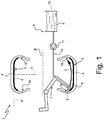
- number 1 indicates, in the entirety thereof, a unit for spiral application, in particular by means of the extrusion, of a sealing fluid 2 on an inner surface 3 of a pneumatic tyre 4.
- the application unit 1 is part of a production line for run-flat pneumatic tyres.
- the application unit 1 comprises a rolling device (schematically illustrated with broken lines) which is suitable for making the pneumatic tyre 4 rotate about a central axis of rotation X and along a rolling direction D (illustrated in figures 5 and 6 ).
- Application unit 1 further comprises an extrusion head 5 provided with a die 6 that is suitable for delivering the sealing fluid 2, and a manipulation device 7, in particular an anthropomorphic or Cartesian robot, which supports the extrusion head 5 and is suitable for arranging the extrusion head 5 inside the pneumatic tyre 4 and for moving the extrusion head 5.
- a manipulation device 7 in particular an anthropomorphic or Cartesian robot, which supports the extrusion head 5 and is suitable for arranging the extrusion head 5 inside the pneumatic tyre 4 and for moving the extrusion head 5.
- the die 6 defines a nozzle 8 and is provided internally with a cavity wherein the sealing fluid 2 flows.
- the extrusion head 5 (provided with the die 6 and carried by the manipulation device 7) is connected to an extrusion system 9 comprising a conduit 10, a pump 11 and a tank 12 containing the sealing fluid 2.
- the manipulation device 7 is suitable for continuously moving the extrusion head 5 from one lateral wall 18 of the pneumatic tyre 4 to the other lateral wall 18 of the pneumatic tyre 4 along a plane orthogonal to the equatorial plane of the pneumatic tyre 4.
- the sealing fluid 2 is a highly viscous polymeric mixture. More particularly, the sealing fluid 2 is a highly viscous and highly adhesive polymeric mixture suitable for closing any punctures that may be created in the tread.
- the die 6 comprises a pair of application apertures 13 and 14 having an elongated shape that are separate and independent therebetween, parallel and adjacent therebetween.
- the application apertures 13 and 14 permit the (simultaneous) outflow of the sealing fluid 2 from the cavity of the die 6; in other words, the sealing fluid 2 flows (simultaneously) from the cavity of the die 6 by means of the two application apertures 13 and 14.
- the bead of sealing fluid 2 applied on the inner surface 3 is subdivided into two adjacent beads, the global disuniformity effect whereof, even if they themselves undergo an elastic retraction, is substantially reduced (cut by half).
- each application aperture 13 or 14 has two larger sides 15 which define a length L13 or L14 of the application aperture 13 or 14 and two smaller sides 16 which define a width W13 or W14 of the application aperture 13 or 14.
- the application apertures 13 and 14 are offset therebetween along a direction parallel to the smaller sides 16.
- offset is intended to mean that the axes of symmetry (or rather the center lines) of the two application apertures 13 and 14 do not coincide (in other words, they are parallel to one another and arranged at a certain distance, not zero, one from the other).
- the two application apertures 13 and 14 are offset therebetween also along a direction parallel to the larger sides 15. This makes it is possible to apply more beads of sealing fluid 2 on the inner surface 3 in a same pass and with the desired overlap.
- the larger sides 15 of the application aperture 13 have the same length as the larger sides 15 of the application aperture 14 (in other words, the length L13 and the length L14 are equal).
- the two application apertures 13 and 14 are offset therebetween along a direction parallel to the larger sides 15 over a quarter of the length L13 and L14 of the larger sides 15; in other words, as illustrated in figure 2 , the two application apertures 13 and 14 face one another half of their length L13 and 14.
- the two application apertures 13 and 14 have a length L13 and L14 substantially equal to 25 mm and are offset with respect to a transversal axis of symmetry over a quarter of such length L13 and L14 along a direction parallel to the larger sides 15, that is, 6.25 mm.
- the larger sides 15 of the application aperture 13 are longer than the larger sides 15 of the application aperture 14; in other words, the length L13 is greater than the length L14.
- the larger sides 15 of the application aperture 13 are more than twice as long as the larger sides 15 of the application aperture 14; in other words, the length L13 is more than twice the length L14.
- the application aperture 14 has a length L14 substantially equal to one third the length L13 of the application aperture 13; in other words, the length L13 of the application aperture 13 is triple the length L14 of the application aperture 14. According to one possible embodiment, the length L14 could be equal to 8.33 mm.
- the two application apertures 13 and 14 are centered with respect to one another along a direction parallel to the larger sides 15; in other words, the transversal axes of symmetry thereof substantially coincide with one another and, in particular, with an axis T of symmetry of the nozzle 8.
- the two application apertures 13 and 14 are offset with respect to one another also along a direction parallel to the larger sides 15; in other words, their transversal axes of symmetry do not coincide with one another, and, in particular, neither coincides with the axis T of symmetry of the nozzle 8.
- the larger sides 15 of the application aperture 13 are three times as long as the larger sides 15 of the application aperture 14 (in other words, the length L13 is substantially 3 times the length L14.
- the two application apertures 13 and 14 are offset therebetween also along a direction parallel to the larger sides 15 over a sixth of the length of the larger sides 15 of the first application aperture 13.
- the two application apertures 13 and 14 have widths that differ therebetween. In other words, according to such embodiments the widths W13 and W14 are different therebetween.
- the width W13 or W14 of at least one application aperture 13 or 14 varies progressively along the extension of the application aperture 13 or 14 itself; in other words, the width W13 or W14 of at least one application aperture 13 or 14 is not constant along the extension of the application aperture 13 or 14 itself.
- the width W13 or W14 of at least one application aperture 13 or 14 can increase from the two ends of the application aperture 13 or 14 up to a maximum at the center of the application aperture 13 or 14 itself.
- the width W13 or W14 of at least one application aperture 13 or 14 varies progressively.
- the width W13 or W14 of at least one application aperture 13 or 14 decreases from the two ends of the application aperture 13 or 14 down to a minimum at the center of the application aperture 13 or 14 itself.
- the bead of sealing fluid 2 deposited on the inner surface 3 of the pneumatic tyre 4 has a sinusoidal section having some maximums corresponding to the ends of the application aperture 13 and some minimums corresponding to the transversal axis of symmetry of the application aperture 13.
- the application aperture 14 is appropriately placed for adding sealing fluid 2, which compensates for the valleys left by the sealing fluid 2 coming out of the application aperture 13.
- the application apertures 13 and 14 are offset therebetween along an axis V perpendicular to the inner surface 3 of the pneumatic tyre 4.
- the application aperture 14 is arranged downstream from the first application aperture 13 along the rolling direction D of the pneumatic tyre 4 and is located at a greater distance from the inner surface 3 than the first application aperture 13. In this way, it is possible to apply the sealing fluid 2 on the inner surface 3 keeping the application apertures 13 and 14 at a minimum distance from the inner surface 3 itself (in other words, from the pneumatic tyre 4), especially in proximity to the overlap zone between the two beads of sealing fluid 2 deposited in a same pass from the extrusion head 5 (as illustrated in figure 5 ).
- the application apertures 13 and 14 are located in the same plane, they must be arranged at a distance from the inner surface 3 at least equal to the sum of the thicknesses of the two beads of sealing fluid 2 deposited in a same pass by the extrusion head 5.
- the application aperture 13 is located at a shorter distance from the inner surface 3 than the application aperture 14, the latter must nevertheless be placed at a distance from the inner surface 3 at least equal to the sum of the thicknesses of the deposited beads of sealing fluid, while the application aperture 13 can be placed at a distance equal to the thickness of only the bead of sealing fluid 2 that flows from the application aperture 13 itself.
- the die 6 comprises a third application aperture 17 with an elongated shape which is separate and independent from the application apertures 13 and 14, is parallel and adjacent to the application apertures 13 and 14, and permits the sealing fluid 2 to flow from the inner cavity of the nozzle 8 in addition to the application apertures 13 and 14.
- the application unit 1 described above is utilized for the application of a sealing fluid 2.
- the unit 1 can be used in other types of machines for the production of pneumatic tyres 4 whereupon the interior or exterior whereof various fluids are applied or in different positions of the pneumatic tyres 4 themselves.
- the feed unit described above has many advantages.
- the application unit 1 described above allows for the application, in a controlled manner, of the sealing fluid inside a pneumatic tyre 4, generating a layer of sealing fluid 2 that is more uniform and less sinusoidal (therefore with peaks and valleys) than the techniques of the prior art.
- the unit 1 makes it possible to utilize a lesser quantity of sealing fluid 2 nevertheless guaranteeing a minimum thickness of the layer of sealing fluid 2.
- the application unit 11 described above makes it possible to reduce the wasting of material and the environmental impact that results from the disposal of the worn-out pneumatic tyres.
- the application unit 11 described above utilizing the possibility of simultaneously creating more passes of sealing fluid in a same cycle of the die 6 inside the pneumatic tyre 4 (ensuring the required overlap between two adjacent passes), makes it possible to consistently reduce the period of time required for the application of the sealing fluid 2 inside the pneumatic tyre 4.
Landscapes
- Engineering & Computer Science (AREA)
- Mechanical Engineering (AREA)
- Manufacturing & Machinery (AREA)
- Extrusion Moulding Of Plastics Or The Like (AREA)
- Tires In General (AREA)
- Coating Apparatus (AREA)
Abstract
Description
- The present invention relates to a unit for the spiral application of a sealing fluid on an inner surface of a pneumatic tyre.
- As is known, a pneumatic tyre comprises a toroidal carcass which has two annular beads and which supports an annular tread. A tread belt is interposed between the carcass and the tread which comprises a number of tread plies. The carcass supports a pair of sidewalls arranged between the tread and the beads. An innerliner is arranged inside the body ply which is airtight, constitutes an inner lining and has the function of retaining the air inside the pneumatic tyre in order to maintain the inflation pressure of the pneumatic tyre itself over time.
- In recent years pneumatic tyre development has been directed towards pneumatic tyres with an inner lining that is manufactured with a sealing fluid that is intended to seal any punctures. Typically, the sealing fluid has a high viscosity in order to ensure both the sealing action in relation to any holes and the stability thereof within the inner cavity regardless of the conditions of the pneumatic tyre.
- Generally speaking, the sealing fluid is applied to the inner surface of a pre-vulcanized pneumatic tyre and preferably in the area of the pneumatic tyre that comes into contact with the road (or the area of the pneumatic tyre wherein punctures can potentially occur). In particular, the sealing fluid is applied at the tread and partially at the sidewalls.
- Typically, the procedure for the application of the sealing fluid includes arranging the already vulcanized pneumatic tyre on a rolling device suitable for making the tyre rotate about a central axis of rotation and along a rolling direction. In response to a command, a manipulation device moves an extrusion head (provided with a die suitable for delivering the sealing fluid with a predefined shape) so as to insert it in the inner cavity of the pneumatic tyre in a position directly facing the inner surface.
- The manipulation device is conveniently implemented by means of a mobile arm (for example, an anthropomorphic or Cartesian robot) whereto is connected the die of the extrusion head provided with a nozzle which is intended for the application of a bead having a profile defined by the shape of the extrusion die of the sealing fluid on the inner surface of the pneumatic tyre.
The nozzle comprises a cavity, wherein the sealing fluid flows, and a single application aperture with an elongated shape, which permits the sealing fluid to flow out of the cavity. - In particular, the manipulation device is intended for the application of a bead of sealing fluid by means of an alternating movement (of the manipulation device and, therefore, of the die) between the two lateral ends of the inner surface of the pneumatic tyre, i.e., moving from one bead to the other of the pneumatic tyre itself. More particularly, the arm moves on a plane orthogonal to the equatorial plane of the pneumatic tyre.
- The pneumatic tyre is brought into rotation by the rolling device by means of motorized rollers; the movement (continuous or stepped) of the arm and the rotation of the pneumatic tyre result in the application of the sealing agent. Advantageously in the case of a continuous movement of the arm, the application of the sealing agent follows a spiral progression made up of multiple parallel and axially offset passes.
- In general, the sealing fluid is a very liquid, elastic and sticky compound; because of the elasticity thereof, it is particularly complex to apply it in a uniform manner insofar as, once it flows from the extrusion head, the sealing fluid tends to assume a form of minimum surface tension in an uncontrolled manner.
- In particular, as soon as the sealing fluid flows from the single aperture of the die, the sealing fluid itself undergoes an elastic retraction that carries the extruded material back from the ends of the aperture toward the center of the aperture. In other words, the sides of the extrusion tend to retract and the section of the extruded sealing fluid tends to transform from a parallelogram or rectangle into an ellipsoid or oblong shape.
- As a result, in order to avoid portions of the layer of sealing fluid inside the pneumatic tyre that are too thin (which would be created in the contact zone between two parallel passes) or having zones wherein the sealing fluid is not applied, it is necessary to create a partial overlap.
- The overlap is generally equal to half of the width of the bead of sealing fluid applied between one pass of sealing fluid and the next or passing several times over the same zones of the inner surface before being certain that the layer of sealing fluid has at least a minimum predetermined thickness over the entire interior surface to be coated.
- The prior art further involves the layer of sealing fluid inside the pneumatic tyre having, in transversal section, a pseudo-sinusoidal or in any case, periodic (i.e., with peaks and valleys due to the elastic retraction of the sealing fluid) progression with a maximum at the overlap between two successive passes and the resulting creation of extensive ridges, which make for a substantial waste of material.
-
US2017305210 discloses a pneumatic tyre with noise reduction properties. The pneumatic tyre includes a resonator attached to the inner periphery of the pneumatic tyre. The resonator comprises a tube with an aperture and a cavity connected to the tube. -
EP0080968 discloses a continuous strip of sealing material for punctures, which strip is applied on an inner surface of a pneumatic tyre by means of the placement and adhesion of a plurality of adjacent turns of the strip with the various windings connected by angular crossing portions. -
WO2017138265 discloses a layer of sealing material formed on an inner surface of a pneumatic tyre by a sealing agent in strips. -
EP1634690 discloses an apparatus for producing at least two strips of rubber comprising an extruder for extruding the rubber composed of at least two strips of rubber. - The object of the present invention is to provide a unit for the spiral application of a sealing fluid on an inner surface of a pneumatic tyre which is free of the existing drawbacks described above and, at the same time, is easy and economical to produce.
- According to the present invention, a unit is provided for the spiral application of a sealing fluid on an inner surface of a pneumatic tyre according to that claimed within the appended claims.
- The claims describe preferred embodiments of the present invention forming an integral part of the present description.
- The present invention is now described in reference to the attached drawings, which illustrate several non-limiting exemplary embodiments, wherein:
-
figure 1 is a frontal and schematic sectional view of a unit for the spiral application of a sealing fluid on an inner surface of a pneumatic tyre produced according to the present invention; -
figure 2 is a frontal and schematic view of a die of an extrusion head of the unit for the spiral application offigure 1 ; -
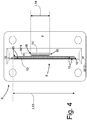
figures 3 and4 are two frontal and schematic views of other variants of the die offigure 2 ; -
figure 5 is a lateral and schematic view of a different embodiment of the die offigure 2 ; and -
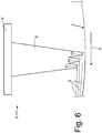
figure 6 is a lateral and schematic view of a further embodiment of the die offigure 2 . - In
figure 1 , number 1 indicates, in the entirety thereof, a unit for spiral application, in particular by means of the extrusion, of asealing fluid 2 on aninner surface 3 of apneumatic tyre 4. - Advantageously, but not necessarily, the application unit 1 is part of a production line for run-flat pneumatic tyres.
- In the embodiment illustrated in
figure 1 , the application unit 1 comprises a rolling device (schematically illustrated with broken lines) which is suitable for making thepneumatic tyre 4 rotate about a central axis of rotation X and along a rolling direction D (illustrated infigures 5 and6 ). - Application unit 1 further comprises an
extrusion head 5 provided with adie 6 that is suitable for delivering thesealing fluid 2, and amanipulation device 7, in particular an anthropomorphic or Cartesian robot, which supports theextrusion head 5 and is suitable for arranging theextrusion head 5 inside thepneumatic tyre 4 and for moving theextrusion head 5. - According to the illustration in
figure 2 , the die 6 defines anozzle 8 and is provided internally with a cavity wherein the sealingfluid 2 flows. - According to the non-limiting embodiment illustrated in
figure 1 , the extrusion head 5 (provided with thedie 6 and carried by the manipulation device 7) is connected to an extrusion system 9 comprising aconduit 10, apump 11 and atank 12 containing thesealing fluid 2. Themanipulation device 7 is suitable for continuously moving theextrusion head 5 from onelateral wall 18 of thepneumatic tyre 4 to the otherlateral wall 18 of thepneumatic tyre 4 along a plane orthogonal to the equatorial plane of thepneumatic tyre 4. - In particular, the sealing
fluid 2 is a highly viscous polymeric mixture. More particularly, the sealingfluid 2 is a highly viscous and highly adhesive polymeric mixture suitable for closing any punctures that may be created in the tread. - According to the illustration in
figure 2 , the die 6 comprises a pair ofapplication apertures application apertures fluid 2 from the cavity of thedie 6; in other words, the sealingfluid 2 flows (simultaneously) from the cavity of thedie 6 by means of the twoapplication apertures fluid 2 applied on theinner surface 3 is subdivided into two adjacent beads, the global disuniformity effect whereof, even if they themselves undergo an elastic retraction, is substantially reduced (cut by half). In fact, in the event the two orifices are offset at a distance equal to half of the application step, this disuniformity would have double the frequency resulting lower magnitude. As a result, it is possible, by increasing the number ofapplication apertures uniform sealing fluid 2. The use of a single aperture would necessitate a greater number of revolutions in order to obtain the same number of passes and the completion of theinner surface 3 of the pneumatic tyre would require a longer period of time for the application thereof. In the case of a bead subdivided into two, this period of time would in fact be doubled. - Advantageously, but not necessarily, each
application aperture larger sides 15 which define a length L13 or L14 of theapplication aperture smaller sides 16 which define a width W13 or W14 of theapplication aperture - Advantageously, but not necessarily, the
application apertures smaller sides 16. - The term "offset" is intended to mean that the axes of symmetry (or rather the center lines) of the two
application apertures - In several possible non-limiting embodiments (illustrated, for example, in
figures 2 and4 ), the twoapplication apertures larger sides 15. This makes it is possible to apply more beads of sealingfluid 2 on theinner surface 3 in a same pass and with the desired overlap. - Advantageously, but not necessarily and as illustrated in the non-limiting embodiment of
figure 2 , thelarger sides 15 of theapplication aperture 13 have the same length as thelarger sides 15 of the application aperture 14 (in other words, the length L13 and the length L14 are equal). Furthermore, advantageously but not necessarily and as illustrated in the non-limiting embodiment offigure 2 , the twoapplication apertures larger sides 15 over a quarter of the length L13 and L14 of thelarger sides 15; in other words, as illustrated infigure 2 , the twoapplication apertures - According to several possible non-limiting embodiments, the two
application apertures larger sides 15, that is, 6.25 mm. - According to the non-limiting embodiments illustrated in
figures 3 and4 , thelarger sides 15 of theapplication aperture 13 are longer than thelarger sides 15 of theapplication aperture 14; in other words, the length L13 is greater than the length L14. - Advantageously, but not necessarily, the
larger sides 15 of theapplication aperture 13 are more than twice as long as thelarger sides 15 of theapplication aperture 14; in other words, the length L13 is more than twice the length L14. - Advantageously, but not necessarily, the
application aperture 14 has a length L14 substantially equal to one third the length L13 of theapplication aperture 13; in other words, the length L13 of theapplication aperture 13 is triple the length L14 of theapplication aperture 14. According to one possible embodiment, the length L14 could be equal to 8.33 mm. - By virtue of the increased instability of the sealing
fluid 2, based on the composition of the sealingfluid 2 itself, it is possible to vary the position and the dimensions of theapplication apertures fluid 2 emitted by theapplication aperture 14 compensates as much as possible for the valleys caused by the elastic retraction of the sealingfluid 2 emitted from theapplication aperture 13 for the purpose of obtaining a uniform layer; for example, it is possible to maintain constant the dimensions of theapplication aperture 13 and to vary the position and the dimensions of theapplication aperture 14. - According to the non-limiting embodiment illustrated in
figure 3 , the twoapplication apertures larger sides 15; in other words, the transversal axes of symmetry thereof substantially coincide with one another and, in particular, with an axis T of symmetry of thenozzle 8. - According to the further and non-limiting embodiment illustrated in
figure 4 , the twoapplication apertures larger sides 15; in other words, their transversal axes of symmetry do not coincide with one another, and, in particular, neither coincides with the axis T of symmetry of thenozzle 8. - According to several non-limiting embodiments, the
larger sides 15 of theapplication aperture 13 are three times as long as thelarger sides 15 of the application aperture 14 (in other words, the length L13 is substantially 3 times the length L14. - According to further non-limiting embodiments, the two
application apertures larger sides 15 over a sixth of the length of thelarger sides 15 of thefirst application aperture 13. - In several non-limiting and unillustrated embodiments, the two
application apertures - In other non-limiting and unillustrated cases, the width W13 or W14 of at least one
application aperture application aperture application aperture application aperture application aperture application aperture application aperture - In further non-limiting and unillustrated cases, the width W13 or W14 of at least one
application aperture application aperture application aperture application aperture fluid 2 deposited on theinner surface 3 of thepneumatic tyre 4 has a sinusoidal section having some maximums corresponding to the ends of theapplication aperture 13 and some minimums corresponding to the transversal axis of symmetry of theapplication aperture 13. As a result, theapplication aperture 14 is appropriately placed for adding sealingfluid 2, which compensates for the valleys left by the sealingfluid 2 coming out of theapplication aperture 13. - Advantageously, but not necessarily and as illustrated in the non-limiting embodiment of
figure 5 , theapplication apertures inner surface 3 of thepneumatic tyre 4. - In particular, the
application aperture 14 is arranged downstream from thefirst application aperture 13 along the rolling direction D of thepneumatic tyre 4 and is located at a greater distance from theinner surface 3 than thefirst application aperture 13. In this way, it is possible to apply the sealingfluid 2 on theinner surface 3 keeping theapplication apertures inner surface 3 itself (in other words, from the pneumatic tyre 4), especially in proximity to the overlap zone between the two beads of sealingfluid 2 deposited in a same pass from the extrusion head 5 (as illustrated infigure 5 ). In other words, in the case wherein theapplication apertures inner surface 3 at least equal to the sum of the thicknesses of the two beads of sealingfluid 2 deposited in a same pass by theextrusion head 5. Instead, if theapplication aperture 13 is located at a shorter distance from theinner surface 3 than theapplication aperture 14, the latter must nevertheless be placed at a distance from theinner surface 3 at least equal to the sum of the thicknesses of the deposited beads of sealing fluid, while theapplication aperture 13 can be placed at a distance equal to the thickness of only the bead of sealingfluid 2 that flows from theapplication aperture 13 itself. This results in being unnecessary but advantageous insofar as during the extrusion the sealingfluid 2 rapidly enters into contact with theinner surface 3 of thepneumatic tyre 4 and, in attaching itself to saidinner surface 3, undergoes an elastic retraction that is less significant than that which it would have if the distance between theapplication aperture 13 and the inner surface were greater. - Advantageously, but not necessarily and as illustrated in the non-limiting embodiment of
figure 6 , thedie 6 comprises athird application aperture 17 with an elongated shape which is separate and independent from theapplication apertures application apertures fluid 2 to flow from the inner cavity of thenozzle 8 in addition to theapplication apertures - That which has been described so far is obviously valid even in the case of three or more apertures.
- In the embodiments illustrated in the attached figures, the application unit 1 described above is utilized for the application of a sealing
fluid 2. According to other unillustrated embodiments, the unit 1 can be used in other types of machines for the production ofpneumatic tyres 4 whereupon the interior or exterior whereof various fluids are applied or in different positions of thepneumatic tyres 4 themselves. - The embodiments described herein may be combined without departing from the scope of protection of the present invention.
- The feed unit described above has many advantages.
- In the first place, the application unit 1 described above allows for the application, in a controlled manner, of the sealing fluid inside a
pneumatic tyre 4, generating a layer of sealingfluid 2 that is more uniform and less sinusoidal (therefore with peaks and valleys) than the techniques of the prior art. - Furthermore, specifically because of the leveling of the layer of sealing
fluid 2 applied, the unit 1 makes it possible to utilize a lesser quantity of sealingfluid 2 nevertheless guaranteeing a minimum thickness of the layer of sealingfluid 2. As a result, theapplication unit 11 described above makes it possible to reduce the wasting of material and the environmental impact that results from the disposal of the worn-out pneumatic tyres. - Lastly, the
application unit 11 described above, utilizing the possibility of simultaneously creating more passes of sealing fluid in a same cycle of thedie 6 inside the pneumatic tyre 4 (ensuring the required overlap between two adjacent passes), makes it possible to consistently reduce the period of time required for the application of the sealingfluid 2 inside thepneumatic tyre 4. -
- 1
- application unit
- 2
- sealing fluid
- 3
- inner surface
- 4
- pneumatic tyre
- 5
- extrusion head
- 6
- die
- 7
- manipulation device
- 8
- nozzle
- 9
- extrusion system
- 10
- conduit
- 11
- valve
- 12
- tank
- 13
- application aperture
- 14
- application aperture
- 15
- larger sides
- 16
- smaller sides
- 17
- third aperture
- 18
- sidewall
- X
- central axis of rotation
- D
- rolling direction
- L13
- length
- L14
- length
- W13
- width
- W14
- width
- T
- transversal axis of symmetry
- V
- axis
Claims (16)
- Spiral application unit (1) of a sealing fluid (2) on an inner surface (3) of a pneumatic tyre (4); the application unit (1) comprises:a rolling device suitable for making the pneumatic tyre (4) rotate about a central axis (X) of rotation and along a rolling direction (D);an extrusion head (5) provided with a die (6) suitable for delivering the sealing fluid (2); anda manipulation device (7) that supports the extrusion head (5) and is suitable for arranging the extrusion head (5) inside the pneumatic tyre (4) and for moving the extrusion head (5) itself;wherein the die (6) comprises a cavity wherein the sealing fluid (2) flows and a first application aperture (13) with an elongated shape which permits the sealing fluid (2) to flow out of the cavity;the application unit (1) is characterized in that the die (6) comprises at least a second application aperture (14) with an elongated shape which is separate and independent from the first application aperture (13), is parallel and adjacent to the first application aperture (13), and permits the sealing fluid (2) to flow out of the cavity in addition to the first application aperture (13).
- Application unit (1) according to claim 1, wherein:each application aperture (13, 14) has two larger sides (15) which define a length (L13, L14) of the application aperture (13, 14) and two smaller sides (16) which define a width (W13, W14) of the application aperture (13, 14); andthe two application apertures (13, 14) are offset therebetween along a direction parallel to the smaller sides (16) .
- Application unit (1) according to claim 2, wherein the two application apertures (13, 14) are offset therebetween also along a direction parallel to the larger sides (15).
- Application unit (1) according to claim 3, wherein:the larger sides (15) of the first application aperture (13) have the same length as the larger sides (15) of the second application aperture (14); andthe two application apertures (13, 14) are offset therebetween along a direction parallel to the larger sides (15) over a quarter of the length (L13, L14) of the larger sides (15).
- Application unit (1) according to claim 2 or 3, wherein the larger sides (15) of the first application aperture (13) are longer than the larger sides (15) of the second application aperture (14).
- Application unit (1) according to claim 5, wherein the larger sides (15) of the first application aperture (13) are more than twice as long as the larger sides (15) of the second application aperture (14).
- Application unit (1) according to claim 5 or 6, wherein the two application apertures (13, 14) are centered with respect to one another along a direction parallel to the larger sides (15).
- Application unit (1) according to claim 5 or 6, wherein the two application apertures (13, 14) are offset therebetween also along a direction parallel to the larger sides (15).
- Application unit (1) according to claim 8, wherein:the larger sides (15) of the first application aperture (13) are three times longer the length of the larger sides (15) of the second application aperture (14); andthe two application apertures (13, 14) are offset therebetween also along a direction parallel to the larger sides (15) over a sixth of the length (L13, L14) of the larger sides (15) of the first application aperture (13).
- Application unit (1) according to any one of claims 1 to 9, wherein the two application apertures (13, 14) have two different widths (W13, W14).
- Application unit (1) according to any one of the claims from 1 to 10, wherein the width (W13, W14) of at least one application aperture (13, 14) varies progressively, in particular it increases from the two ends of the application aperture (13, 14) up to a maximum at the center of the application aperture (13, 14) itself.
- Application unit (1) according to any one of the claims from 1 to 10, wherein the width (W13, W14) of at least one application aperture (13, 14) varies progressively, in particular decreases from the two ends of the application aperture (13, 14) down to a minimum at the center of the application aperture (13, 14) itself.
- Application unit (1) according to any one of the claims from 1 to 12, wherein the application apertures (13, 14) are offset therebetween along an axis (V) perpendicular to the inner surface (3) of the pneumatic tyre (4).
- Application unit (1) according to claim 13, wherein the second application aperture (14) is arranged downstream from the first application aperture (13) along the rolling direction (D) of the pneumatic tyre and is located at a greater distance from the inner surface (3) than the first application aperture (13).
- Application unit (1) according to any one of claims 1 to 14, wherein the die (6) comprises a third application aperture (17) with an elongated shape which is separate and independent from the first and second application apertures (13, 14), is parallel and adjacent to the first and second application apertures (13, 14), and permits the sealing fluid (2) to flow from the cavity in addition to the first and second application apertures (13, 14).
- Application unit (1) according to any one of the claims from 1 to 15, wherein the sealing fluid (2) is a mixture of rubber and polymers.
Priority Applications (2)
| Application Number | Priority Date | Filing Date | Title |
|---|---|---|---|
| SI201930511T SI3666509T1 (en) | 2018-12-11 | 2019-12-04 | Unit for the spiral application of a sealant fluid inside a tyre |
| RS20230270A RS64109B1 (en) | 2018-12-11 | 2019-12-04 | Unit for the spiral application of a sealant fluid inside a tyre |
Applications Claiming Priority (1)
| Application Number | Priority Date | Filing Date | Title |
|---|---|---|---|
| IT201800010961 | 2018-12-11 |
Publications (2)
| Publication Number | Publication Date |
|---|---|
| EP3666509A1 true EP3666509A1 (en) | 2020-06-17 |
| EP3666509B1 EP3666509B1 (en) | 2023-02-01 |
Family
ID=65861549
Family Applications (1)
| Application Number | Title | Priority Date | Filing Date |
|---|---|---|---|
| EP19213655.4A Active EP3666509B1 (en) | 2018-12-11 | 2019-12-04 | Unit for the spiral application of a sealant fluid inside a tyre |
Country Status (7)
| Country | Link |
|---|---|
| EP (1) | EP3666509B1 (en) |
| ES (1) | ES2942023T3 (en) |
| HU (1) | HUE061543T2 (en) |
| PL (1) | PL3666509T3 (en) |
| PT (1) | PT3666509T (en) |
| RS (1) | RS64109B1 (en) |
| SI (1) | SI3666509T1 (en) |
Citations (6)
| Publication number | Priority date | Publication date | Assignee | Title |
|---|---|---|---|---|
| EP0080968A2 (en) | 1981-11-23 | 1983-06-08 | The Goodyear Tire & Rubber Company | Tire and method of applying sealant |
| JP2004230592A (en) * | 2003-01-28 | 2004-08-19 | Yokohama Rubber Co Ltd:The | Tread rubber molding equipment for tires |
| JP2005111826A (en) * | 2003-10-08 | 2005-04-28 | Bridgestone Corp | Extrusion molding apparatus and rubber material extrusion molding method using the same |
| EP1634690A2 (en) | 2004-09-14 | 2006-03-15 | Sumitomo Rubber Industries, Ltd. | Apparatus for producing a rubber strip |
| WO2017138265A1 (en) | 2016-02-08 | 2017-08-17 | 株式会社ブリヂストン | Tire manufacturing method |
| US20170305210A1 (en) | 2014-10-17 | 2017-10-26 | Sumitomo Rubber Industries, Ltd. | Pneumatic tire and method for producing same |
-
2019
- 2019-12-04 ES ES19213655T patent/ES2942023T3/en active Active
- 2019-12-04 RS RS20230270A patent/RS64109B1/en unknown
- 2019-12-04 HU HUE19213655A patent/HUE061543T2/en unknown
- 2019-12-04 SI SI201930511T patent/SI3666509T1/en unknown
- 2019-12-04 PT PT192136554T patent/PT3666509T/en unknown
- 2019-12-04 EP EP19213655.4A patent/EP3666509B1/en active Active
- 2019-12-04 PL PL19213655.4T patent/PL3666509T3/en unknown
Patent Citations (6)
| Publication number | Priority date | Publication date | Assignee | Title |
|---|---|---|---|---|
| EP0080968A2 (en) | 1981-11-23 | 1983-06-08 | The Goodyear Tire & Rubber Company | Tire and method of applying sealant |
| JP2004230592A (en) * | 2003-01-28 | 2004-08-19 | Yokohama Rubber Co Ltd:The | Tread rubber molding equipment for tires |
| JP2005111826A (en) * | 2003-10-08 | 2005-04-28 | Bridgestone Corp | Extrusion molding apparatus and rubber material extrusion molding method using the same |
| EP1634690A2 (en) | 2004-09-14 | 2006-03-15 | Sumitomo Rubber Industries, Ltd. | Apparatus for producing a rubber strip |
| US20170305210A1 (en) | 2014-10-17 | 2017-10-26 | Sumitomo Rubber Industries, Ltd. | Pneumatic tire and method for producing same |
| WO2017138265A1 (en) | 2016-02-08 | 2017-08-17 | 株式会社ブリヂストン | Tire manufacturing method |
Also Published As
| Publication number | Publication date |
|---|---|
| RS64109B1 (en) | 2023-04-28 |
| PT3666509T (en) | 2023-04-11 |
| SI3666509T1 (en) | 2023-05-31 |
| HUE061543T2 (en) | 2023-07-28 |
| PL3666509T3 (en) | 2023-05-29 |
| ES2942023T3 (en) | 2023-05-29 |
| EP3666509B1 (en) | 2023-02-01 |
Similar Documents
| Publication | Publication Date | Title |
|---|---|---|
| CN106794710B (en) | Pneumatic tire and method of making the same | |
| US6666940B2 (en) | Manufacture of a strip by extrusion of a tube then flattening the tube | |
| US10449742B2 (en) | Process and apparatus for building tires for vehicle wheels | |
| KR100991587B1 (en) | How to form annular apex and bead subassemblies | |
| US8617334B2 (en) | Method and apparatus for making a compartmentalized tire sealant strip | |
| US20190061295A1 (en) | Tire manufacturing method | |
| CN103249548A (en) | Adhesive strip, its manufacturing method and manufacturing method of pneumatic tire | |
| US20060090836A1 (en) | Method and apparatus for manufacturing elastomeric material components of a tyre for vehicle wheels | |
| EP3666509B1 (en) | Unit for the spiral application of a sealant fluid inside a tyre | |
| EP1638756B1 (en) | A process for manufacturing elastomeric components of a tyre for vehicle wheels | |
| US8221573B2 (en) | Method and apparatus for building a puncture sealant preassembled component | |
| EP2049324B1 (en) | Process and apparatus for building pneumatic tyres | |
| JP2022076897A (en) | Tire manufacturing equipment | |
| KR20090093936A (en) | Process and Apparatus for Building Pneumatic Tyres | |
| US20080142140A1 (en) | Method and apparatus for building a puncture sealant tire | |
| EP2985136B1 (en) | Method for manufacturing pneumatic tires | |
| EP3655242A1 (en) | Method for controlling a tyre building process, plant for tyre production operating in accordance with said method, processing unit configured for implementing said method, and electronic unit included in said processing unit | |
| US11446853B2 (en) | Tire with variable ribbon size tread and system and method for making same | |
| CN106427000B (en) | Method of forming an elastic belt | |
| EP2646233B1 (en) | Process and plant for building tyres, green tyre and cured tyre obtained thereby. | |
| WO2011077330A1 (en) | Extrusion process and device for producing elastomeric compounds |
Legal Events
| Date | Code | Title | Description |
|---|---|---|---|
| PUAI | Public reference made under article 153(3) epc to a published international application that has entered the european phase |
Free format text: ORIGINAL CODE: 0009012 |
|
| STAA | Information on the status of an ep patent application or granted ep patent |
Free format text: STATUS: THE APPLICATION HAS BEEN PUBLISHED |
|
| AK | Designated contracting states |
Kind code of ref document: A1 Designated state(s): AL AT BE BG CH CY CZ DE DK EE ES FI FR GB GR HR HU IE IS IT LI LT LU LV MC MK MT NL NO PL PT RO RS SE SI SK SM TR |
|
| AX | Request for extension of the european patent |
Extension state: BA ME |
|
| STAA | Information on the status of an ep patent application or granted ep patent |
Free format text: STATUS: REQUEST FOR EXAMINATION WAS MADE |
|
| 17P | Request for examination filed |
Effective date: 20201218 |
|
| RBV | Designated contracting states (corrected) |
Designated state(s): AL AT BE BG CH CY CZ DE DK EE ES FI FR GB GR HR HU IE IS IT LI LT LU LV MC MK MT NL NO PL PT RO RS SE SI SK SM TR |
|
| GRAP | Despatch of communication of intention to grant a patent |
Free format text: ORIGINAL CODE: EPIDOSNIGR1 |
|
| STAA | Information on the status of an ep patent application or granted ep patent |
Free format text: STATUS: GRANT OF PATENT IS INTENDED |
|
| INTG | Intention to grant announced |
Effective date: 20220720 |
|
| GRAS | Grant fee paid |
Free format text: ORIGINAL CODE: EPIDOSNIGR3 |
|
| GRAA | (expected) grant |
Free format text: ORIGINAL CODE: 0009210 |
|
| STAA | Information on the status of an ep patent application or granted ep patent |
Free format text: STATUS: THE PATENT HAS BEEN GRANTED |
|
| AK | Designated contracting states |
Kind code of ref document: B1 Designated state(s): AL AT BE BG CH CY CZ DE DK EE ES FI FR GB GR HR HU IE IS IT LI LT LU LV MC MK MT NL NO PL PT RO RS SE SI SK SM TR |
|
| REG | Reference to a national code |
Ref country code: GB Ref legal event code: FG4D |
|
| REG | Reference to a national code |
Ref country code: CH Ref legal event code: EP Ref country code: AT Ref legal event code: REF Ref document number: 1546824 Country of ref document: AT Kind code of ref document: T Effective date: 20230215 |
|
| REG | Reference to a national code |
Ref country code: DE Ref legal event code: R096 Ref document number: 602019024996 Country of ref document: DE |
|
| REG | Reference to a national code |
Ref country code: IE Ref legal event code: FG4D |
|
| REG | Reference to a national code |
Ref country code: PT Ref legal event code: SC4A Ref document number: 3666509 Country of ref document: PT Date of ref document: 20230411 Kind code of ref document: T Free format text: AVAILABILITY OF NATIONAL TRANSLATION Effective date: 20230404 |
|
| RAP4 | Party data changed (patent owner data changed or rights of a patent transferred) |
Owner name: BRIDGESTONE EUROPE NV/SA |
|
| REG | Reference to a national code |
Ref country code: LT Ref legal event code: MG9D |
|
| REG | Reference to a national code |
Ref country code: ES Ref legal event code: FG2A Ref document number: 2942023 Country of ref document: ES Kind code of ref document: T3 Effective date: 20230529 |
|
| REG | Reference to a national code |
Ref country code: NL Ref legal event code: MP Effective date: 20230201 |
|
| REG | Reference to a national code |
Ref country code: SK Ref legal event code: T3 Ref document number: E 41472 Country of ref document: SK |
|
| REG | Reference to a national code |
Ref country code: AT Ref legal event code: MK05 Ref document number: 1546824 Country of ref document: AT Kind code of ref document: T Effective date: 20230201 |
|
| REG | Reference to a national code |
Ref country code: HU Ref legal event code: AG4A Ref document number: E061543 Country of ref document: HU |
|
| PG25 | Lapsed in a contracting state [announced via postgrant information from national office to epo] |
Ref country code: NO Free format text: LAPSE BECAUSE OF FAILURE TO SUBMIT A TRANSLATION OF THE DESCRIPTION OR TO PAY THE FEE WITHIN THE PRESCRIBED TIME-LIMIT Effective date: 20230501 Ref country code: NL Free format text: LAPSE BECAUSE OF FAILURE TO SUBMIT A TRANSLATION OF THE DESCRIPTION OR TO PAY THE FEE WITHIN THE PRESCRIBED TIME-LIMIT Effective date: 20230201 Ref country code: LV Free format text: LAPSE BECAUSE OF FAILURE TO SUBMIT A TRANSLATION OF THE DESCRIPTION OR TO PAY THE FEE WITHIN THE PRESCRIBED TIME-LIMIT Effective date: 20230201 Ref country code: LT Free format text: LAPSE BECAUSE OF FAILURE TO SUBMIT A TRANSLATION OF THE DESCRIPTION OR TO PAY THE FEE WITHIN THE PRESCRIBED TIME-LIMIT Effective date: 20230201 Ref country code: HR Free format text: LAPSE BECAUSE OF FAILURE TO SUBMIT A TRANSLATION OF THE DESCRIPTION OR TO PAY THE FEE WITHIN THE PRESCRIBED TIME-LIMIT Effective date: 20230201 Ref country code: AT Free format text: LAPSE BECAUSE OF FAILURE TO SUBMIT A TRANSLATION OF THE DESCRIPTION OR TO PAY THE FEE WITHIN THE PRESCRIBED TIME-LIMIT Effective date: 20230201 |
|
| PG25 | Lapsed in a contracting state [announced via postgrant information from national office to epo] |
Ref country code: SE Free format text: LAPSE BECAUSE OF FAILURE TO SUBMIT A TRANSLATION OF THE DESCRIPTION OR TO PAY THE FEE WITHIN THE PRESCRIBED TIME-LIMIT Effective date: 20230201 Ref country code: IS Free format text: LAPSE BECAUSE OF FAILURE TO SUBMIT A TRANSLATION OF THE DESCRIPTION OR TO PAY THE FEE WITHIN THE PRESCRIBED TIME-LIMIT Effective date: 20230601 Ref country code: GR Free format text: LAPSE BECAUSE OF FAILURE TO SUBMIT A TRANSLATION OF THE DESCRIPTION OR TO PAY THE FEE WITHIN THE PRESCRIBED TIME-LIMIT Effective date: 20230502 Ref country code: FI Free format text: LAPSE BECAUSE OF FAILURE TO SUBMIT A TRANSLATION OF THE DESCRIPTION OR TO PAY THE FEE WITHIN THE PRESCRIBED TIME-LIMIT Effective date: 20230201 |
|
| PG25 | Lapsed in a contracting state [announced via postgrant information from national office to epo] |
Ref country code: SM Free format text: LAPSE BECAUSE OF FAILURE TO SUBMIT A TRANSLATION OF THE DESCRIPTION OR TO PAY THE FEE WITHIN THE PRESCRIBED TIME-LIMIT Effective date: 20230201 Ref country code: EE Free format text: LAPSE BECAUSE OF FAILURE TO SUBMIT A TRANSLATION OF THE DESCRIPTION OR TO PAY THE FEE WITHIN THE PRESCRIBED TIME-LIMIT Effective date: 20230201 Ref country code: DK Free format text: LAPSE BECAUSE OF FAILURE TO SUBMIT A TRANSLATION OF THE DESCRIPTION OR TO PAY THE FEE WITHIN THE PRESCRIBED TIME-LIMIT Effective date: 20230201 Ref country code: CZ Free format text: LAPSE BECAUSE OF FAILURE TO SUBMIT A TRANSLATION OF THE DESCRIPTION OR TO PAY THE FEE WITHIN THE PRESCRIBED TIME-LIMIT Effective date: 20230201 |
|
| REG | Reference to a national code |
Ref country code: DE Ref legal event code: R097 Ref document number: 602019024996 Country of ref document: DE |
|
| PLBE | No opposition filed within time limit |
Free format text: ORIGINAL CODE: 0009261 |
|
| STAA | Information on the status of an ep patent application or granted ep patent |
Free format text: STATUS: NO OPPOSITION FILED WITHIN TIME LIMIT |
|
| 26N | No opposition filed |
Effective date: 20231103 |
|
| PG25 | Lapsed in a contracting state [announced via postgrant information from national office to epo] |
Ref country code: IT Free format text: LAPSE BECAUSE OF FAILURE TO SUBMIT A TRANSLATION OF THE DESCRIPTION OR TO PAY THE FEE WITHIN THE PRESCRIBED TIME-LIMIT Effective date: 20230201 |
|
| REG | Reference to a national code |
Ref country code: CH Ref legal event code: PL |
|
| PG25 | Lapsed in a contracting state [announced via postgrant information from national office to epo] |
Ref country code: MC Free format text: LAPSE BECAUSE OF FAILURE TO SUBMIT A TRANSLATION OF THE DESCRIPTION OR TO PAY THE FEE WITHIN THE PRESCRIBED TIME-LIMIT Effective date: 20230201 |
|
| GBPC | Gb: european patent ceased through non-payment of renewal fee |
Effective date: 20231204 |
|
| REG | Reference to a national code |
Ref country code: BE Ref legal event code: MM Effective date: 20231231 |
|
| PG25 | Lapsed in a contracting state [announced via postgrant information from national office to epo] |
Ref country code: MC Free format text: LAPSE BECAUSE OF FAILURE TO SUBMIT A TRANSLATION OF THE DESCRIPTION OR TO PAY THE FEE WITHIN THE PRESCRIBED TIME-LIMIT Effective date: 20230201 |
|
| REG | Reference to a national code |
Ref country code: IE Ref legal event code: MM4A |
|
| PG25 | Lapsed in a contracting state [announced via postgrant information from national office to epo] |
Ref country code: IE Free format text: LAPSE BECAUSE OF NON-PAYMENT OF DUE FEES Effective date: 20231204 |
|
| PG25 | Lapsed in a contracting state [announced via postgrant information from national office to epo] |
Ref country code: GB Free format text: LAPSE BECAUSE OF NON-PAYMENT OF DUE FEES Effective date: 20231204 |
|
| PG25 | Lapsed in a contracting state [announced via postgrant information from national office to epo] |
Ref country code: BE Free format text: LAPSE BECAUSE OF NON-PAYMENT OF DUE FEES Effective date: 20231231 |
|
| PG25 | Lapsed in a contracting state [announced via postgrant information from national office to epo] |
Ref country code: CH Free format text: LAPSE BECAUSE OF NON-PAYMENT OF DUE FEES Effective date: 20231231 |
|
| PG25 | Lapsed in a contracting state [announced via postgrant information from national office to epo] |
Ref country code: IE Free format text: LAPSE BECAUSE OF NON-PAYMENT OF DUE FEES Effective date: 20231204 Ref country code: GB Free format text: LAPSE BECAUSE OF NON-PAYMENT OF DUE FEES Effective date: 20231204 Ref country code: CH Free format text: LAPSE BECAUSE OF NON-PAYMENT OF DUE FEES Effective date: 20231231 Ref country code: BE Free format text: LAPSE BECAUSE OF NON-PAYMENT OF DUE FEES Effective date: 20231231 |
|
| PG25 | Lapsed in a contracting state [announced via postgrant information from national office to epo] |
Ref country code: BG Free format text: LAPSE BECAUSE OF FAILURE TO SUBMIT A TRANSLATION OF THE DESCRIPTION OR TO PAY THE FEE WITHIN THE PRESCRIBED TIME-LIMIT Effective date: 20230201 |
|
| PG25 | Lapsed in a contracting state [announced via postgrant information from national office to epo] |
Ref country code: BG Free format text: LAPSE BECAUSE OF FAILURE TO SUBMIT A TRANSLATION OF THE DESCRIPTION OR TO PAY THE FEE WITHIN THE PRESCRIBED TIME-LIMIT Effective date: 20230201 |
|
| PG25 | Lapsed in a contracting state [announced via postgrant information from national office to epo] |
Ref country code: CY Free format text: LAPSE BECAUSE OF FAILURE TO SUBMIT A TRANSLATION OF THE DESCRIPTION OR TO PAY THE FEE WITHIN THE PRESCRIBED TIME-LIMIT; INVALID AB INITIO Effective date: 20191204 |
|
| PGFP | Annual fee paid to national office [announced via postgrant information from national office to epo] |
Ref country code: PT Payment date: 20251121 Year of fee payment: 7 |
|
| PG25 | Lapsed in a contracting state [announced via postgrant information from national office to epo] |
Ref country code: TR Free format text: LAPSE BECAUSE OF FAILURE TO SUBMIT A TRANSLATION OF THE DESCRIPTION OR TO PAY THE FEE WITHIN THE PRESCRIBED TIME-LIMIT Effective date: 20230201 |
|
| PGFP | Annual fee paid to national office [announced via postgrant information from national office to epo] |
Ref country code: LU Payment date: 20251119 Year of fee payment: 7 |
|
| PGFP | Annual fee paid to national office [announced via postgrant information from national office to epo] |
Ref country code: DE Payment date: 20251126 Year of fee payment: 7 |
|
| PGFP | Annual fee paid to national office [announced via postgrant information from national office to epo] |
Ref country code: HU Payment date: 20251212 Year of fee payment: 7 Ref country code: FR Payment date: 20251120 Year of fee payment: 7 |
|
| PGFP | Annual fee paid to national office [announced via postgrant information from national office to epo] |
Ref country code: PL Payment date: 20251119 Year of fee payment: 7 |
|
| PGFP | Annual fee paid to national office [announced via postgrant information from national office to epo] |
Ref country code: SK Payment date: 20251124 Year of fee payment: 7 Ref country code: RO Payment date: 20251203 Year of fee payment: 7 |
|
| PGFP | Annual fee paid to national office [announced via postgrant information from national office to epo] |
Ref country code: RS Payment date: 20251126 Year of fee payment: 7 |
|
| PGFP | Annual fee paid to national office [announced via postgrant information from national office to epo] |
Ref country code: SI Payment date: 20251125 Year of fee payment: 7 |
|
| PGFP | Annual fee paid to national office [announced via postgrant information from national office to epo] |
Ref country code: ES Payment date: 20260102 Year of fee payment: 7 |