EP3666433A1 - Drilling tool - Google Patents
Drilling tool Download PDFInfo
- Publication number
- EP3666433A1 EP3666433A1 EP18212364.6A EP18212364A EP3666433A1 EP 3666433 A1 EP3666433 A1 EP 3666433A1 EP 18212364 A EP18212364 A EP 18212364A EP 3666433 A1 EP3666433 A1 EP 3666433A1
- Authority
- EP
- European Patent Office
- Prior art keywords
- drilling tool
- chip space
- drill
- flutes
- section
- Prior art date
- Legal status (The legal status is an assumption and is not a legal conclusion. Google has not performed a legal analysis and makes no representation as to the accuracy of the status listed.)
- Granted
Links
- 238000005553 drilling Methods 0.000 title claims abstract description 83
- 238000005520 cutting process Methods 0.000 claims abstract description 28
- 239000002826 coolant Substances 0.000 claims description 24
- 229910052751 metal Inorganic materials 0.000 claims description 3
- 239000002184 metal Substances 0.000 claims description 3
- 238000004519 manufacturing process Methods 0.000 claims description 2
- 239000000314 lubricant Substances 0.000 description 8
- 230000002349 favourable effect Effects 0.000 description 4
- 239000000463 material Substances 0.000 description 4
- 238000011161 development Methods 0.000 description 3
- 230000018109 developmental process Effects 0.000 description 3
- 238000009826 distribution Methods 0.000 description 3
- 239000002131 composite material Substances 0.000 description 2
- 239000011159 matrix material Substances 0.000 description 2
- 238000000034 method Methods 0.000 description 2
- 239000002245 particle Substances 0.000 description 2
- 206010010774 Constipation Diseases 0.000 description 1
- 230000001133 acceleration Effects 0.000 description 1
- 239000000956 alloy Substances 0.000 description 1
- 229910045601 alloy Inorganic materials 0.000 description 1
- 230000009286 beneficial effect Effects 0.000 description 1
- 239000011230 binding agent Substances 0.000 description 1
- 230000015572 biosynthetic process Effects 0.000 description 1
- 229910017052 cobalt Inorganic materials 0.000 description 1
- 239000010941 cobalt Substances 0.000 description 1
- GUTLYIVDDKVIGB-UHFFFAOYSA-N cobalt atom Chemical compound [Co] GUTLYIVDDKVIGB-UHFFFAOYSA-N 0.000 description 1
- 230000001419 dependent effect Effects 0.000 description 1
- 230000000694 effects Effects 0.000 description 1
- 210000001061 forehead Anatomy 0.000 description 1
- 238000000608 laser ablation Methods 0.000 description 1
- 150000001247 metal acetylides Chemical class 0.000 description 1
- 229910052759 nickel Inorganic materials 0.000 description 1
- 230000003287 optical effect Effects 0.000 description 1
- 230000000737 periodic effect Effects 0.000 description 1
- UONOETXJSWQNOL-UHFFFAOYSA-N tungsten carbide Chemical compound [W+]#[C-] UONOETXJSWQNOL-UHFFFAOYSA-N 0.000 description 1
Images


Classifications
-
- B—PERFORMING OPERATIONS; TRANSPORTING
- B23—MACHINE TOOLS; METAL-WORKING NOT OTHERWISE PROVIDED FOR
- B23B—TURNING; BORING
- B23B51/00—Tools for drilling machines
- B23B51/02—Twist drills
-
- B—PERFORMING OPERATIONS; TRANSPORTING
- B23—MACHINE TOOLS; METAL-WORKING NOT OTHERWISE PROVIDED FOR
- B23B—TURNING; BORING
- B23B51/00—Tools for drilling machines
- B23B51/06—Drills with lubricating or cooling equipment
-
- B—PERFORMING OPERATIONS; TRANSPORTING
- B24—GRINDING; POLISHING
- B24B—MACHINES, DEVICES, OR PROCESSES FOR GRINDING OR POLISHING; DRESSING OR CONDITIONING OF ABRADING SURFACES; FEEDING OF GRINDING, POLISHING, OR LAPPING AGENTS
- B24B19/00—Single-purpose machines or devices for particular grinding operations not covered by any other main group
- B24B19/02—Single-purpose machines or devices for particular grinding operations not covered by any other main group for grinding grooves, e.g. on shafts, in casings, in tubes, homokinetic joint elements
- B24B19/022—Single-purpose machines or devices for particular grinding operations not covered by any other main group for grinding grooves, e.g. on shafts, in casings, in tubes, homokinetic joint elements for helicoidal grooves
-
- B—PERFORMING OPERATIONS; TRANSPORTING
- B24—GRINDING; POLISHING
- B24B—MACHINES, DEVICES, OR PROCESSES FOR GRINDING OR POLISHING; DRESSING OR CONDITIONING OF ABRADING SURFACES; FEEDING OF GRINDING, POLISHING, OR LAPPING AGENTS
- B24B19/00—Single-purpose machines or devices for particular grinding operations not covered by any other main group
- B24B19/02—Single-purpose machines or devices for particular grinding operations not covered by any other main group for grinding grooves, e.g. on shafts, in casings, in tubes, homokinetic joint elements
- B24B19/04—Single-purpose machines or devices for particular grinding operations not covered by any other main group for grinding grooves, e.g. on shafts, in casings, in tubes, homokinetic joint elements for fluting drill shanks
-
- B—PERFORMING OPERATIONS; TRANSPORTING
- B23—MACHINE TOOLS; METAL-WORKING NOT OTHERWISE PROVIDED FOR
- B23B—TURNING; BORING
- B23B2251/00—Details of tools for drilling machines
- B23B2251/40—Flutes, i.e. chip conveying grooves
- B23B2251/406—Flutes, i.e. chip conveying grooves of special form not otherwise provided for
-
- B—PERFORMING OPERATIONS; TRANSPORTING
- B23—MACHINE TOOLS; METAL-WORKING NOT OTHERWISE PROVIDED FOR
- B23B—TURNING; BORING
- B23B2251/00—Details of tools for drilling machines
- B23B2251/44—Margins, i.e. the narrow portion of the land which is not cut away to provide clearance on the circumferential surface
- B23B2251/443—Double margin drills
Definitions
- the present invention relates to a drilling tool with the features of the preamble of claim 1.
- Generic drilling tools in particular twist drills, comprise a cylindrical base body on which helical webs and flutes are formed between webs.
- the angle at which the flutes are inclined to a central axis of the twist drill is the twist angle (also referred to as the helix angle) of the twist drill.
- the helix angle can vary over the length of the drill bit.
- twist drills have two helical flutes.
- the flutes allow chips to be removed.
- a chip space extension created in this way creates additional volume for picking up and removing chips.
- broadening of the chip space means that a free cross-section of a flute is enlarged compared to the actual tool grinding.
- the object of the present invention is to provide an improved drilling tool.
- the drilling tool according to the invention is designed in such a way that the chip space widening grips a web, so that a web width in the area of the chip space widening is reduced.
- the chip space of the tool is increased at the expense of the web.
- the web is therefore narrower in the area of the chip space expansion than in a section of the drilling tool in which no chip space expansion is formed.
- Chip space extensions from the prior art are designed as local depressions in chip flutes at the bottom.
- the creation of additional chip space by known chip space extensions is limited when the load-bearing cross-section of the drilling tool, ie the core diameter, is weakened.
- a chip space extension according to the invention extends a flute laterally by reducing a web width.
- additional chip space can be created by deepening the flute at the bottom.
- the expansion of the chip space according to the invention favors the removal of chips. A tendency to constipation is reduced.
- Chip space extensions are preferably formed on all flutes of the drilling tool. Of course, it can also be provided that a chip space extension is formed only on one flute. However, for a uniform mechanical load on the drilling tool, it is cheaper to provide chip space extensions on all flutes.
- the change in shape of the flute due to the expansion of the chip space according to the invention accelerates the chips, which promotes chip breakage.
- Acceleration is understood to mean that the chips experience a change in momentum.
- the change in momentum occurs primarily as a change in the direction of movement of the chips, that is to say through a chip deflection, due to the inventive configuration of the chip space extension.
- a web has a secondary cutting edge on the side lying in the direction of rotation.
- the web width is preferably reduced on the side of the web facing away from the secondary cutting edge, so that the shape of the secondary cutting edge remains unaffected by the expansion of the chip space. This ensures a smooth chip flow.
- the chip space extension is designed such that only the side of a web facing away from a direction of rotation is covered by the chip space extension.
- a further advantage of the invention is that a significant increase in the chip volume can be created within a short path.
- short path it is meant that the broadening of the chip space along a small angular range - based on a course of the helical flutes - or in other words, within a short distance - based on a longitudinal extension of the drilling tool - can be realized.
- the widening of the chip space preferably increases a slot opening angle of a flute.
- the slot opening angle is understood to mean that angle which the opposite flanks of a flute enclose with one another.
- the broadening of the chip space viewed from the drill face in the direction of the shank section, only begins at a distance from the drill face.
- the front part of the cutting section does not have an expansion of the chip space.
- the broadening of the chip space preferably begins at a distance from the drill face of greater than or equal to 1 ⁇ D, with D being the drill diameter.
- guide chamfers are formed on webs at least over part of the cutting section.
- Guide chamfers viewed from the drill face in the direction of the shaft section, are particularly preferred up to a distance from the drill face of less than or equal to 3 ⁇ D.
- two guide chamfers are formed on a web.
- the broadening of the chip space does not begin until after the area of the cutting section on which guide chamfers are formed. This has the advantage that the webs have their original width in the area of the guide chamfers, which is favorable for guiding or supporting the drill.
- the expansion of the chip space achieved by the broadening of the chip space increases along the longitudinal axis of the drill.
- the broadening of the chip space does not have to be constant, but can increase along the longitudinal axis of the drill. For mechanical reasons, it is favorable if the broadening of the chip space increases continuously, that is to say not abruptly.
- the increase in the chip space widening, based on a course of the chip flutes takes place within less than or equal to 360 °. This describes the characteristic already mentioned that the expansion of the chip space reaches the desired dimension within a short distance. At 360 °, the span expansion would increase from a start value to the desired final dimension within one revolution of a helical flute.
- the enlargement of the chip space extension can take place, for example, along a projected distance of less than or equal to 2.5 x the drill diameter D.
- the widening of the chip space increases along a first projected distance in the direction of the shaft section in order then to remain constant along a second projected distance in the direction of the shaft section.
- the broadening of the chip space is preferably designed as a ground joint. This means that the broadening of the chip space is preferably introduced by grinding. Alternatively, material could be removed by other methods, such as laser ablation.
- the flute has a variable depth in the area of the chip space expansion.
- depth is meant a distance from an outer surface of the drilling tool to the base of the flute.
- the depth can preferably increase in the direction of the shaft section. This also means that the depth and the lateral dimension of the chip space extension can be varied independently of one another.
- At least one coolant channel running in the interior of the drilling tool is formed.
- a coolant / lubricant can be delivered to the drill face via a coolant channel. This particularly advantageously supports the function of the drilling tool, since the coolant / lubricant further promotes removal of chips with reduced friction. The measures thus have a particularly advantageous effect on one another.
- the drilling tool is preferably formed from a composite material comprising at least one hard material and at least one binder phase.
- the drilling tool is made of hard metal.
- hard metal is understood to mean a composite material in which hard particles, which can be formed in particular by carbides, carbonitrides and / or oxocarbonitrides of the elements from groups IVb to VIb of the periodic table of the elements, are embedded in a ductile metallic matrix which is composed in particular of Co , Ni, Fe or an alloy of these can be formed.
- the hard particles are at least predominantly formed by tungsten carbide and the metallic matrix consists essentially of cobalt.
- Protection is also sought after for a method of making a drilling tool.
- a rotating grinding tool is moved along the flutes to create a widening of the chip space, a plane of rotation of the grinding tool being inclined at an angle to the longitudinal axis of the drill, which angle is greater than the helix angle of the corresponding flute.
- the grinding tool is guided in such a way that material is removed on those sides of the webs which are at the back with respect to a direction of rotation.
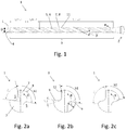
- Figure 1 shows a drilling tool 1 as a spiral drill with an essentially cylindrical base body with a drill diameter D, which has a shank section 2 and a cutting section 3.
- the shaft section 2 is only partially shown.
- the drilling tool 1 rotates in the direction of rotation R with the longitudinal axis L as the axis of rotation.
- the present drilling tool 1 is therefore clockwise.
- the drilling tool 1 has a drill face 4 (also: drill tip) on which main cutting edges are formed.
- Helical flutes 5 are formed along the drilling tool 1. In the present example, there are two diametrically opposite flutes 5. Alternatively, flutes 5 can also be arranged asymmetrically. More than two flutes 5 could also be provided.
- the flutes 5 run at a swirl angle ⁇ to the longitudinal axis L of the drilling tool 1. Both flutes 5 preferably have the same swirl angle.
- the surface of the web 7, which determines a lateral surface of the drilling tool 1, is referred to as the cutting back 8.
- the edge formed by a flute 5 and the web 7 and lying in the direction of rotation R is referred to as secondary cutting edge 11.
- the cutting section 3 is divided into three subsections: no chip space widening 9 is formed along a distance SpErw1 from the drill face 4.
- the length of the first section SpErw1 from the drill face 4 without a chip space extension 9 is preferably greater than or equal to 1 ⁇ D, with D drill diameter.
- a chip space extension 9 begins, which increases along a second projected section SpErw2 in the direction of the shaft section 3, in order then to remain constant along a third projected section SpErw3 in the direction of the shaft section 3.
- the length of the first section SpErw1 is 2.5 x D in the present example
- the length of the section SpErw2 is 2.6 x D in the present example.
- Figure 2a shows a cross section of the drilling tool 1 in the area of the first section SpErw1 without a chip space extension 9.
- the shape and depth of the flutes 5 therefore corresponds to the original tool grinding in this illustration.
- the flute 5 without chip space extension 9 has a slot opening angle of x °, in this example approximately 68 °.
- the groove opening angle is the angle between the legs drawn as dashed auxiliary lines, which connect a center of the drilling tool 1 and an edge between the flute 5 and the cutting back 8.
- auxiliary lines which connect a center of the drilling tool 1 and an edge between the flute 5 and the cutting back 8.
- Figure 2b shows a cross section of the drilling tool 1 at a distance SpErw1 from the drill face 4.
- the enlargement of the slot opening angle is indicated by the dashed line as a measure for the chip space extension 9 along the distance SpErw2 by the angle y °, in this example 18 °.
- the chip space widening 9 consists in a material decrease on the side of a web 7 facing away from the direction of rotation (R), so that a web width b in the area of the chip space widening 9 is reduced.
- the web is therefore narrower in the area of the chip space widening 9 than in a section of the drilling tool 1 in which no chip space widening 9 is formed.
- the web width b can be determined, for example, by an optical measuring method.
- the edge between the cutting back 8 and the flute 5 in the direction of rotation R carries an auxiliary cutting edge 11 of the drilling tool 1 and remains unaffected by the chip space extension 9.
- the chip space extension 9 could capture the webs 7 on both sides of the flute. However, it is more favorable for a smooth chip flow if the secondary cutting edge 11 remains unaffected by the chip space widening 9. A depth t of the flute 5 can also be seen, which remains unchanged in this example.
- Figure 2c shows a cross section of the drilling tool 1 in the region of the third section SpErw3.
- the chip space widening 9 takes place at the expense of the webs 7 on the side facing away from the direction of rotation R.
- the web width b has a difference from the situation in FIG Figure 2a reduced to the value b2.
- a depth t of the flutes 5 remains unchanged in this embodiment. In other words, a core diameter is not reduced. Provision can also be made to increase the depth t of the flutes 5 in addition to the described lateral expansion of the flutes.
- Figure 3 shows a drilling tool 1 according to a further embodiment.
- the reference numerals correspond Figure 1 .
- chamfers 10 are formed here on the webs along the route SpErw1.
- Guide chamfers 10 bring about a favorable guidance and support of the drilling tool 1 with low friction.
- the guide chamfers 10 are realized here by a recess on the cutting back 8, so that there is one guide chamfer 10 on the secondary cutting edge 11 per web 7 and another guide chamfer 10 on the side of the web 7 facing away from the direction of rotation R.
- the chip space widening 9 only begins after the section of the cutting section 3 on which the guide chamfers 10 are formed.
- the support by the guide chamfers 10 thus takes place over a larger angular range in comparison to guide chamfers 10 on a web 7 with a reduced web width b.
- Figure 4a shows a cross section of the drilling tool 1 in the region of the line SpErw1, on which the guide chamfers 10 are formed. It can be seen that the guide chamfers 10 are formed by a recess on the cutting back 8. The guide chamfers 10 are distributed at angular intervals of approximately 90 ° along the circumference of the drilling tool 1, whereby uniform support and guidance of the drilling tool 1 is achieved.
- the length of the path SpErw1, on which the guide chamfers 10 are formed is 3.5 x the drill diameter D in the present example.
- FIG 4b shows a section in section SpErw2, in which the chip space extension 9 begins.
- the chip space widening 9 is designed such that the web width b on a web 7 is reduced on the side facing away from the direction of rotation 7.
- the secondary cutting edge 11 remains unaffected by the chip space extension 9.
- the web 7 is therefore not reduced in its web width b from both sides.
- the web width b is reduced along the section SpErw2 from the original value b1 to the value b2. In the SpErw2 section, no guide chamfers are formed on the webs 7.
- Figure 4c shows a cross section of the drilling tool 1 in the region of the third section SpErw3.
- the web width b has a difference from the situation in FIG Figure 4a reduced to the value b2.
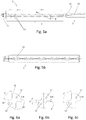
- FIG. 5a shows a drilling tool 1 according to a further embodiment. Coolant channels 12 running inside the drilling tool 1 are provided here. Guide chamfers 10 are formed in the area of the line 14.
- a coolant / lubricant can be conveyed to the drill face 4 through the coolant channels 12.
- the coolant channels 12 are twisted at a spiral angle to the longitudinal axis L.
- the function of the inventive drilling tool 1 is particularly advantageously supported by the coolant / lubricant which can be conveyed to the drill face 4 via coolant channels 12, since the coolant / lubricant further promotes the removal of chips.
- a distributor chamber 13 for the coolant / lubricant is provided in the shaft section 2. Via the distribution chamber 13, the coolant / lubricant can advantageously be clamped (not shown) to the Drilling tool 1 are handed over.
- This embodiment with a distributor chamber 13 is particularly interesting for particularly long tools and / or tools with small diameters in order to keep a flow resistance for the coolant / lubricant low.
- Figure 5b shows a detail of a drilling tool 1 according to a further embodiment. Here is in contrast to the embodiment of
- FIGS 6a to 6c show cross sections of drilling tools 1 with coolant channels 12.
- Figure 6a shows a cross section of the drilling tool 1 in the region of the line 14 along which the guide chamfers 10 are formed.
- the internal coolant channels 12 can be seen in the cross section of the drilling tool 1.
- the coolant channels 12 have a circular cross section.
- Figure 6b shows a section in section SpErw2, in which the chip space extension 9 begins.
- the chip space widening 9 is designed such that the web width b on a web 7 is reduced on the side facing away from the direction of rotation 7.
- coolant channels 12 are arranged such that there is a sufficient distance from the chip space widening 9 in order not to weaken the web 7 in the area of the coolant channels 12.
- Figure 6c shows a cross section of the drilling tool 1 in the region of the third section SpErw3.
- coolant channels 12 are independent of the presence of guide chamfers 10. Drilling tools 1 with coolant channels 12 without guide chamfers 10 can therefore exist.
- Figure 7 shows a photograph of a drilling tool 1 according to the invention.
- the chip space widening 9 is emphasized, which is formed at the expense of the webs 7 on the side facing away from the direction of rotation R.
- Grinding grooves are indicated by arrows, which are generated by an engagement of a rotating grinding tool (not shown), in particular a profile grinding wheel.
- the chip space widening 9 produced by the engagement of the grinding tool has a main direction of extension X, which extends at an angle ⁇ to the longitudinal axis L of the drill, the angle ⁇ being greater than the helix angle ⁇ of the corresponding flute 5.
- the chip space extension 9 is preferably produced by an engagement of the grinding tool such that a plane of rotation of the grinding tool is set at an angle ⁇ to the longitudinal axis L of the drilling tool 1 and then the flute 5 is moved relative to the drilling tool 1, so that webs 7 on the Direction of rotation R side are partially removed.
- Figure 8 shows a further photograph of a drilling tool 1 according to the invention. It can be seen that in the region of the chip space widening 9 a web width b2 of the web 7 is reduced compared to a region in the longitudinal direction in front of it with a web width b1.
Abstract
Bohrwerkzeug (1), insbesondere Spiralbohrer, mit einem im Wesentlichen zylindrischen Grundkörper, umfassend einen Schaftabschnitt (2), einen Schneidenabschnitt (3) mit einem Bohrerdurchmesser (D),
eine Bohrerstirn (4), eine Bohrerlängsachse (L) um welche das Bohrwerkzeug in einer Drehrichtung (R) drehbar ist,
mit wenigstens zwei entlang der Bohrerlängsachse (L) in wenigstens einem Drallwinkel (β) geneigten, verdrallt verlaufenden Spannuten (5), welche Spannuten (5) einen Spanraum (6) bilden,
zwischen den Spannuten (5) ausgebildeten Stegen (7) mit einer Stegbreite (b), wobei in wenigstens eine der Spannuten (5) wenigstens abschnittsweise eine Spanraumerweiterung (9) zur Vergrößerung des Spanraums (6) eingebracht ist, wobei die Stegbreite (b) im Bereich der Spanraumerweiterung (9) reduziert ist.

a drill face (4), a drill longitudinal axis (L) about which the drilling tool can be rotated in a direction of rotation (R),
with at least two twisted flutes (5) which are inclined and twisted along the longitudinal axis (L) of the drill at at least one twist angle (β) and which flutes (5) form a chip space (6),
webs (7) with a web width (b) formed between the flutes (5), a chip space widening (9) for enlarging the chip space (6) being introduced at least in sections into at least one of the flutes (5), the web width (b) is reduced in the area of the chip space extension (9).
Description
Die vorliegende Erfindung betrifft ein Bohrwerkzeug mit den Merkmalen des Oberbegriffs von Anspruch 1.The present invention relates to a drilling tool with the features of the preamble of
Gattungsgemäße Bohrwerkzeuge, insbesondere Spiralbohrer, umfassen einen zylindrischen Grundkörper, an welchem wendelförmig Stege und zwischen Stegen Spannuten ausgebildet sind. Der Winkel, in welchem die Spannuten zu einer Mittelachse des Spiralbohrers geneigt verläuft, ist der Drallwinkel (auch als Spiralwinkel bezeichnet) des Spiralbohrers. Der Drallwinkel kann über die Länge des Spiralbohrers veränderlich sein.Generic drilling tools, in particular twist drills, comprise a cylindrical base body on which helical webs and flutes are formed between webs. The angle at which the flutes are inclined to a central axis of the twist drill is the twist angle (also referred to as the helix angle) of the twist drill. The helix angle can vary over the length of the drill bit.
In der Regel weisen Spiralbohrer zwei wendelförmige Spannuten auf.As a rule, twist drills have two helical flutes.
Die Spannuten ermöglichen einen Abtransport von Spänen.The flutes allow chips to be removed.
Aus dem Stand der Technik ist es bekannt, die Spannuten eines Bohrwerkzeugs durch Aufschleifen zu vergrößern.It is known from the prior art to enlarge the flutes of a drilling tool by grinding.
Eine so geschaffene Spanraumerweiterung schafft zusätzliches Volumen zur Aufnahme und Abtransport von Spänen. Spanraumerweiterung bedeutet allgemein, dass ein freier Querschnitt einer Spannut gegenüber dem eigentlichen Werkzeugschliff vergrößert wird.A chip space extension created in this way creates additional volume for picking up and removing chips. In general, broadening of the chip space means that a free cross-section of a flute is enlarged compared to the actual tool grinding.
Aufgabe der vorliegenden Erfindung ist es, ein verbessertes Bohrwerkzeug anzugeben.The object of the present invention is to provide an improved drilling tool.
Die Aufgabe wird erfüllt durch ein Bohrwerkzeug mit den Merkmalen von Anspruch 1. Bevorzugte Weiterbildungen sind in den abhängigen Ansprüchen angegeben.The object is achieved by a drilling tool with the features of
Das erfindungsgemäße Bohrwerkzeug ist so ausgebildet, dass die Spanraumerweiterung einen Steg erfasst, sodass eine Stegbreite im Bereich der Spanraumerweiterung reduziert ist. In anderen Worten wird der Spanraum des Werkzeugs auf Kosten des Steges vergrößert. Der Steg ist also im Bereich der Spanraumerweiterung schmäler als in einem Abschnitt des Bohrwerkzeugs, in dem keine Spanraumerweiterung ausgebildet ist.The drilling tool according to the invention is designed in such a way that the chip space widening grips a web, so that a web width in the area of the chip space widening is reduced. In other words, the chip space of the tool is increased at the expense of the web. The web is therefore narrower in the area of the chip space expansion than in a section of the drilling tool in which no chip space expansion is formed.
Spanraumerweiterungen aus dem Stand der Technik sind als lokale Vertiefungen von Spannuten an deren Grund ausgebildet. Die Schaffung zusätzlichen Spanraums durch bekannte Spanraumerweiterungen ist dadurch limitiert, als der tragende Querschnitt des Bohrwerkzeugs, also der Kerndurchmesser, geschwächt wird.Chip space extensions from the prior art are designed as local depressions in chip flutes at the bottom. The creation of additional chip space by known chip space extensions is limited when the load-bearing cross-section of the drilling tool, ie the core diameter, is weakened.
Eine erfindungsgemäße Spanraumerweiterung erweitert eine Spannut hingegen lateral, indem eine Stegbreite reduziert wird. Zusätzlich kann natürlich auch weiterer Spanraum durch Vertiefung der Spannut an deren Grund erzeugt werden.By contrast, a chip space extension according to the invention extends a flute laterally by reducing a web width. In addition, of course, additional chip space can be created by deepening the flute at the bottom.
Die erfindungsgemäße Spanraumerweiterung begünstigt einen Abtransport von Spänen. Eine Verstopfungsneigung wird reduziert.The expansion of the chip space according to the invention favors the removal of chips. A tendency to constipation is reduced.
Bevorzugt sind Spanraumerweiterungen an allen Spannuten des Bohrwerkzeugs ausgebildet. Es kann natürlich auch vorgesehen sein, eine Spanraumerweiterung nur an einer Spannut auszubilden. Für eine gleichmäßige mechanische Belastung des Bohrwerkzeugs ist es aber günstiger, Spanraumerweiterungen an allen Spannuten vorzusehen.Chip space extensions are preferably formed on all flutes of the drilling tool. Of course, it can also be provided that a chip space extension is formed only on one flute. However, for a uniform mechanical load on the drilling tool, it is cheaper to provide chip space extensions on all flutes.
Durch die Formänderung der Spannut durch die erfindungsgemäße Spanraumerweiterung erfahren die Späne eine Beschleunigung, was einen Spanbruch begünstigt.The change in shape of the flute due to the expansion of the chip space according to the invention accelerates the chips, which promotes chip breakage.
Beschleunigung ist so zu verstehen, dass die Späne eine Impulsänderung erfahren. Die Impulsänderung tritt durch die erfindungsgemäße Ausgestaltung der Spanraumerweiterung vorwiegend als Veränderung der Bewegungsrichtung der Späne, also durch eine Spanumlenkung auf.Acceleration is understood to mean that the chips experience a change in momentum. The change in momentum occurs primarily as a change in the direction of movement of the chips, that is to say through a chip deflection, due to the inventive configuration of the chip space extension.
Ein Steg weist auf der in Drehrichtung liegenden Seite eine Nebenschneide auf. Die Verringerung der Stegbreite erfolgt bevorzugt auf der der Nebenschneide abgewandten Seite des Steges, damit die Form der Nebenschneide von der Spanraumerweiterung unbeeinflusst bleibt. Auf diese Weise ist ein sanfter Spanablauf gegeben.A web has a secondary cutting edge on the side lying in the direction of rotation. The web width is preferably reduced on the side of the web facing away from the secondary cutting edge, so that the shape of the secondary cutting edge remains unaffected by the expansion of the chip space. This ensures a smooth chip flow.
In anderen Worten ist die gemäß dieser Weiterbildung die Spanraumerweiterung so ausgebildet, dass nur die einer Drehrichtung abgewandte Seite eines Steges von der Spanraumerweiterung erfasst ist.In other words, according to this development, the chip space extension is designed such that only the side of a web facing away from a direction of rotation is covered by the chip space extension.
Neben der erwähnten Spanumlenkung besteht ein weiterer Vorteil der Erfindung auch darin, dass eine deutliche Vergrößerung des Spanvolumens innerhalb eines kurzen Wegs geschaffen werden kann. Mit kurzem Weg ist gemeint, dass die Spanraumerweiterung entlang eines kleinen Winkelbereichs - bezogen auf einen Verlauf der wendelförmigen Spannuten - oder anders ausgedrückt, innerhalb einer kurzen Strecke - bezogen auf eine Längserstreckung des Bohrwerkzeugs - realisiert werden kann.In addition to the chip deflection mentioned, a further advantage of the invention is that a significant increase in the chip volume can be created within a short path. By short path it is meant that the broadening of the chip space along a small angular range - based on a course of the helical flutes - or in other words, within a short distance - based on a longitudinal extension of the drilling tool - can be realized.
Besonders interessant ist das für Mikrobohrer, da hier die Spanräume entsprechend klein und kurz sind.This is particularly interesting for micro drills, since the chip spaces here are correspondingly small and short.
Bevorzugt vergrößert sich durch die Spanraumerweiterung ein Nutöffnungswinkel einer Spannut. Unter Nutöffnungswinkel wird im Rahmen dieser Anmeldung jener Winkel verstanden, den die gegenüberliegenden Flanken einer Spannut miteinander einschließen.The widening of the chip space preferably increases a slot opening angle of a flute. In the context of this application, the slot opening angle is understood to mean that angle which the opposite flanks of a flute enclose with one another.
Bevorzugt ist vorgesehen, dass die Spanraumerweiterung, von der Bohrerstirn in Richtung Schaftabschnitt betrachtet, erst bei einem Abstand von der Bohrerstirn einsetzt. In anderen Worten kann also vorgesehen sein, dass der vordere Teil des Schneidenabschnitts keine Spanraumerweiterung aufweist. Bevorzugt beginnt die Spanraumerweiterung erst bei einem Abstand von der Bohrerstirn von größer oder gleich 1 x D, mit D ist der Bohrerdurchmesser. Der Vorteil dieser Weiterbildung ist, dass im besagten Teil des Schneidenabschnitts ohne Spanraumerweiterung die volle Stegbreite erhalten ist und das Bohrwerkzeug dadurch im Spanbildungsbereich robuster ist. Es hat sich gezeigt, dass der Abschnitt ohne Spanraumerweiterung nicht zu lang sein soll, da sonst die günstigen Effekte der daran anschließenden Spanraumerweiterung nicht zur vollen Entfaltung kommen. Als Richtwert konnte festgestellt werden, dass die Spanraumerweiterung höchstens bei einem Abstand von der Bohrerstirn von 8 x D einsetzen soll, da ansonsten die Späne zu lang werden.It is preferably provided that the broadening of the chip space, viewed from the drill face in the direction of the shank section, only begins at a distance from the drill face. In other words, it can be provided that the front part of the cutting section does not have an expansion of the chip space. The broadening of the chip space preferably begins at a distance from the drill face of greater than or equal to 1 × D, with D being the drill diameter. The advantage of this development is that the full web width is obtained in the part of the cutting section without widening the chip space, and the drilling tool is therefore more robust in the area of chip formation. It has been shown that the section without the expansion of the span should not be too long, since otherwise the beneficial effects of the subsequent expansion of the span will not be fully developed. As a guideline it could be determined that the chip space expansion should start at a distance of 8 x D from the drill face, otherwise the chips would become too long.
Bevorzugt ist vorgesehen, dass zumindest über einen Teil des Schneidenabschnitts Führungsfasen an Stegen ausgebildet sind. Insbesondere bevorzugt sind Führungsfasen, von der Bohrerstirn in Richtung Schaftabschnitt betrachtet, bis zu einem Abstand von der Bohrerstirn von kleiner oder gleich 3 x D ausgebildet.It is preferably provided that guide chamfers are formed on webs at least over part of the cutting section. Guide chamfers, viewed from the drill face in the direction of the shaft section, are particularly preferred up to a distance from the drill face of less than or equal to 3 × D.
Insbesondere bevorzugt sind an einem Steg zwei Führungsfasen ausgebildet.Particularly preferably, two guide chamfers are formed on a web.
Weiter bevorzugt ist vorgesehen, dass die Spanraumerweiterung, von der Bohrerstirn in Richtung Schaftabschnitt betrachtet, erst nach dem Bereich des Schneidenabschnitts einsetzen, an dem Führungsfasen ausgebildet sind. Dies hat den Vorteil, dass die Stege im Bereich der Führungsfasen ihre ursprüngliche Breite aufweisen, was günstig für eine Führung bzw. Abstützung des Bohrers ist.It is further preferably provided that the broadening of the chip space, viewed from the drill face in the direction of the shank section, does not begin until after the area of the cutting section on which guide chamfers are formed. This has the advantage that the webs have their original width in the area of the guide chamfers, which is favorable for guiding or supporting the drill.
Bevorzugt ist vorgesehen, dass die von der Spanraumerweiterung erzielte Erweiterung des Spanraums entlang der Bohrerlängsachse zunimmt.It is preferably provided that the expansion of the chip space achieved by the broadening of the chip space increases along the longitudinal axis of the drill.
Die Spanraumerweiterung muss also nicht konstant sein, sondern kann entlang der Bohrerlängsachse zunehmen. Aus mechanischen Gründen günstig ist es, wenn die Spanraumerweiterung kontinuierlich, also nicht sprunghaft zunimmt.The broadening of the chip space does not have to be constant, but can increase along the longitudinal axis of the drill. For mechanical reasons, it is favorable if the broadening of the chip space increases continuously, that is to say not abruptly.
Bevorzugt ist vorgesehen, dass wobei die Zunahme der Spanraumerweiterung, bezogen auf einen Verlauf der Spannuten, innerhalb von kleiner oder gleich 360° erfolgt. Dies beschreibt die bereits erwähnte Ausprägung, dass die Spanraumerweiterung innerhalb eines kurzen Weges das gewünschte Maß erreicht. Bei 360° würde also innerhalb einer Umdrehung einer wendelförmigen Spannut die Spanraumerweiterung von einem Startwert auf das gewünschte Endmaß anwachsen.It is preferably provided that the increase in the chip space widening, based on a course of the chip flutes, takes place within less than or equal to 360 °. This describes the characteristic already mentioned that the expansion of the chip space reaches the desired dimension within a short distance. At 360 °, the span expansion would increase from a start value to the desired final dimension within one revolution of a helical flute.
Bezogen auf die Bohrerlängsachse kann die Vergrößerung der Spanraumerweiterung beispielsweise entlang einer projizierten Strecke von kleiner oder gleich 2,5 x dem Bohrerdurchmesser D erfolgen.In relation to the longitudinal axis of the drill, the enlargement of the chip space extension can take place, for example, along a projected distance of less than or equal to 2.5 x the drill diameter D.
Bevorzugt ist vorgesehen, dass die Spanraumerweiterung entlang einer ersten projizierten Strecke in Richtung Schaftabschnitt zunimmt, um danach entlang einer zweiten projizierten Strecke in Richtung Schaftabschnitt konstant zu bleiben.It is preferably provided that the widening of the chip space increases along a first projected distance in the direction of the shaft section in order then to remain constant along a second projected distance in the direction of the shaft section.
Bevorzugt ist die Spanraumerweiterung als Einschliff ausgebildet. Das heißt, die Spanraumerweiterung ist bevorzugt durch Schleifen eingebracht. Alternativ könnte Material durch andere Verfahren, wie etwa Laserablation, abgetragen werden.The broadening of the chip space is preferably designed as a ground joint. This means that the broadening of the chip space is preferably introduced by grinding. Alternatively, material could be removed by other methods, such as laser ablation.
Bevorzugt ist vorgesehen, dass die Spannut im Bereich der Spanraumerweiterung eine veränderliche Tiefe aufweist. Mit Tiefe ist ein Abstand von einer Mantelfläche des Bohrwerkzeugs zum Grund der Spannut gemeint. Bevorzugt kann die Tiefe in Richtung Schaftabschnitt zunehmen. Damit wird auch zum Ausdruck gebracht, dass die Tiefe und die laterale Abmessung der Spanraumerweiterung unabhängig voneinander variierbar sind.It is preferably provided that the flute has a variable depth in the area of the chip space expansion. By depth is meant a distance from an outer surface of the drilling tool to the base of the flute. The depth can preferably increase in the direction of the shaft section. This also means that the depth and the lateral dimension of the chip space extension can be varied independently of one another.
Bevorzugt ist vorgesehen, dass wenigstens ein im Inneren des Bohrwerkzeugs verlaufender Kühlmittelkanal ausbildet ist. Über einen Kühlmittelkanal kann ein Kühl- / Schmiermittel an die Bohrerstirn gefördert werden. Damit wird die Funktion des Bohrwerkzeugs besonders vorteilhaft unterstützt, da das Kühl- / Schmiermittel einen Abtransport von Spänen bei verringerter Reibung weiter begünstigt. Somit wirken die Maßnahmen besonders vorteilhaft miteinander.It is preferably provided that at least one coolant channel running in the interior of the drilling tool is formed. A coolant / lubricant can be delivered to the drill face via a coolant channel. This particularly advantageously supports the function of the drilling tool, since the coolant / lubricant further promotes removal of chips with reduced friction. The measures thus have a particularly advantageous effect on one another.
Bevorzugt ist das Bohrwerkzeug aus einem Verbundwerkstoff umfassend wenigstens einen Hartstoff und wenigstens eine Binderphase ausgebildet. Insbesondere ist das Bohrwerkzeug aus Hartmetall gefertigt. Unter Hartmetall wird vorliegend ein Verbundwerkstoff verstanden, bei dem harte Teilchen, die insbesondere durch Karbide, Karbonitride und/oder Oxokarbonitride der Elemente der Gruppen IVb bis VIb des Periodensystems der Elemente gebildet sein können, in einer duktilen metallischen Matrix eingebettet sind, die insbesondere aus Co, Ni, Fe oder einer Legierung von diesen gebildet sein kann. In den meisten Fällen sind die harten Teilchen dabei zumindest überwiegend durch Wolframkarbid gebildet und die metallische Matrix besteht im Wesentlichen aus Kobalt.The drilling tool is preferably formed from a composite material comprising at least one hard material and at least one binder phase. In particular, the drilling tool is made of hard metal. In the present case, hard metal is understood to mean a composite material in which hard particles, which can be formed in particular by carbides, carbonitrides and / or oxocarbonitrides of the elements from groups IVb to VIb of the periodic table of the elements, are embedded in a ductile metallic matrix which is composed in particular of Co , Ni, Fe or an alloy of these can be formed. In most cases, the hard particles are at least predominantly formed by tungsten carbide and the metallic matrix consists essentially of cobalt.
Schutz wird auch begehrt für ein Verfahren zur Herstellung eines Bohrwerkzeugs. Dazu ist vorgesehen, dass ein rotierendes Schleifwerkzeug zu Schaffung einer Spanraumerweiterung entlang der Spannuten bewegt wird, wobei eine Rotationsebene des Schleifwerkzeugs in einem Winkel zur Bohrerlängsachse geneigt ist, welcher Winkel größer ist als der Drallwinkel der entsprechenden Spannut. Das Schleifwerkzeug wird dabei so geführt, dass ein Materialabtrag an jenen Seiten der Stege erfolgt, die bezüglich einer Drehrichtung hinten liegen.Protection is also sought after for a method of making a drilling tool. For this purpose, it is provided that a rotating grinding tool is moved along the flutes to create a widening of the chip space, a plane of rotation of the grinding tool being inclined at an angle to the longitudinal axis of the drill, which angle is greater than the helix angle of the corresponding flute. The grinding tool is guided in such a way that material is removed on those sides of the webs which are at the back with respect to a direction of rotation.
Die Erfindung wird anhand der Figuren näher erläutert. Darin zeigt:
- Fig. 1
- ein Ausführungsbeispiel der Erfindung
- Fig. 2a-c
- Querschnitte des
Bohrwerkzeugs von Figur 1 an verschiedenen Stellen entlang der Längsachse - Fig. 3
- ein Bohrwerkzeug in einem weiteren Ausführungsbeispiel
- Fig. 4a-c
- Querschnitte des
Bohrwerkzeugs von Figur 3 an verschiedenen Stellen entlang der Längsachse - Fig. 5a, 5b
- Bohrwerkzeuge in weiteren Ausführungsbeispielen
- Fig. 6a-c
- Querschnitte des
Bohrwerkzeugs von Figur 5 an verschiedenen Stellen entlang der Längsachse - Fig. 7, 8
- fotografische Aufnahmen eines erfindungsgemäßen Bohrwerkzeugs
- Fig. 1
- an embodiment of the invention
- 2a-c
- Cross sections of the drilling tool from
Figure 1 at various points along the longitudinal axis - Fig. 3
- a drilling tool in a further embodiment
- 4a-c
- Cross sections of the drilling tool from
Figure 3 at various points along the longitudinal axis - 5a, 5b
- Drilling tools in other embodiments
- 6a-c
- Cross sections of the drilling tool from
Figure 5 at various points along the longitudinal axis - 7, 8
- photographic recordings of a drilling tool according to the invention
Das Bohrwerkzeug 1 weist eine Bohrerstirn 4 (auch: Bohrerspitze) auf, an welcher Hauptschneiden ausgebildet sind.The
Entlang des Bohrwerkzeugs 1 sind wendelförmig verlaufende Spannuten 5 eingeformt. Im vorliegenden Beispiel sind es zwei sich diametral gegenüberliegende Spannuten 5. Alternativ können Spannuten 5 auch asymmetrisch angeordnet sein. Es könnten auch mehr als zwei Spannuten 5 vorgesehen sein.
Die Spannuten 5 verlaufen in einem Drallwinkel β zur Längsachse L des Bohrwerkzeugs 1. Bevorzugt weisen beide Spannuten 5 den gleichen Drallwinkel auf.The
Zwischen den Spannuten 5 besteht ein Steg 7. Die Oberfläche des Stegs 7, welche eine Mantelfläche des Bohrwerkzeugs 1 bestimmt, wird als Schneidrücken 8 bezeichnet.There is a
Die von einer Spannut 5 und dem Steg 7 gebildete, in Drehrichtung R liegende Kante wird als Nebenschneide 11 bezeichnet.The edge formed by a
Der Schneidenabschnitt 3 ist zur Erläuterung in drei Unterabschnitte eingeteilt: Entlang einer Strecke SpErw1 von der Bohrerstirn 4 ist keine Spanraumerweiterung 9 ausgebildet. Die Länge der ersten Strecke SpErw1 von der Bohrerstirn 4 ohne Spanraumerweiterung 9 ist bevorzugt größer gleich 1 x D, mit D Bohrerdurchmesser.For explanation purposes, the
Nach der ersten Strecke SpErw1 beginnt eine Spanraumerweiterung 9, die entlang einer zweiten projizierten Strecke SpErw2 in Richtung Schaftabschnitt 3 zunimmt, um danach entlang einer dritten projizierten Strecke SpErw3 in Richtung Schaftabschnitt 3 konstant zu bleiben. Die Länge ersten Strecke SpErw1 beträgt im vorliegenden Beispiel 2,5 x D, die Länge der Strecke SpErw2 beträgt im vorliegenden Beispiel 2,6 x D.After the first section SpErw1, a
In den
Die Spannut 5 ohne Spanraumerweiterung 9 weist einen Nutöffnungswinkel von x°, in diesem Beispiel etwa 68° auf. Als Nutöffnungswinkel wird der Winkel zwischen den als strichlierte Hilfslinien eingezeichneten Schenkeln bezeichnet, welche ein Zentrum des Bohrwerkzeugs 1 und eine Kante zwischen der Spannut 5 und Schneidrücken 8 verbinden. Die Bezugszeichen sind in den nachfolgenden Figuren der Übersichtlichkeit halber nicht wiederholt.The
Die Spanraumerweiterung 9 besteht in einer Materialabnahme an der der Drehrichtung (R) abgewandten Seite eines Steges 7, sodass eine Stegbreite b im Bereich der Spanraumerweiterung 9 reduziert ist. Der Steg ist also im Bereich der Spanraumerweiterung 9 schmäler als in einem Abschnitt des Bohrwerkzeugs 1, in dem keine Spanraumerweiterung 9 eingeformt ist.The chip space widening 9 consists in a material decrease on the side of a
Die Stegbreite b kann beispielsweise durch ein optisches Messverfahren ermittelt werden.The web width b can be determined, for example, by an optical measuring method.
Die Kante zwischen dem Schneidrücken 8 und der Spannut 5 in Drehrichtung R trägt bildet eine Nebenschneide 11 des Bohrwerkzeugs 1 und bleibt von der Spanraumerweiterung 9 unbeeinflusst.The edge between the cutting back 8 and the
Alternativ könnte die Spanraumerweiterung 9 die Stege 7 auf beiden Seiten der Spannut erfassen. Allerdings ist es für einen sanften Spanablauf günstiger, wenn die Nebenschneide 11 von der Spanraumerweiterung 9 unberührt bleibt. Weiters ersichtlich ist eine Tiefe t der Spannut 5, die in diesem Beispiel unverändert bleibt.Alternatively, the
Man erkennt weiters, dass die Spanraumerweiterung 9 auf Kosten der Stege 7 auf der der Drehrichtung R abgewandten Seite erfolgt. Die Stegbreite b hat sich gegenüber dem Wert b1 von der Situation in
Eine Tiefe t der Spannuten 5 bleibt in diesem Ausführungsbeispiel unverändert. In anderen Worten reduziert sich ein Kerndurchmesser nicht. Es kann auch vorgesehen sein, zusätzlich zur beschriebenen lateralen Erweiterung der Spannuten auch noch die Tiefe t der Spannuten 5 zu vergrößern.A depth t of the
Die Führungsfasen 10 sind hier durch eine Ausnehmung am Schneidrücken 8 realisiert, sodass pro Steg 7 eine Führungsfase 10 an der Nebenschneide 11 und eine weitere Führungsfase 10 an der bezüglich der Drehrichtung R abgewandten Seite des Steges 7 vorliegt.The guide chamfers 10 are realized here by a recess on the cutting back 8, so that there is one
In diesem bevorzugten Ausführungsbeispiel setzt die Spanraumerweiterung 9 erst nach dem Abschnitt des Schneidenabschnitts 3 ein, an welchem die Führungsfasen 10 ausgebildet sind. Dies hat den Vorteil, dass die Stegbreite b im Bereich der Führungsfasen 10 unverändert breit ist, wodurch eine günstige Abstützung des Bohrwerkzeugs 1 erzielt wird. So erfolgt die Abstützung durch die Führungsfasen 10 über einen größeren Winkelbereich im Vergleich zu Führungsfasen 10 an einem Steg 7 mit verringerter Stegbreite b.In this preferred exemplary embodiment, the chip space widening 9 only begins after the section of the
Aus
Die Länge der Strecke SpErw1, an der die Führungsfasen 10 ausgebildet sind, beträgt im vorliegen Beispiel 3,5 x dem Bohrerdurchmesser D.The length of the path SpErw1, on which the guide chamfers 10 are formed, is 3.5 x the drill diameter D in the present example.
Für die Nutöffnungswinkel gilt das anhand der
Bezüglich der übrigen Bezugszeichen gilt das für die vorherigen Ausführungsbeispiele gesagte.With regard to the remaining reference numerals, what has been said for the previous exemplary embodiments applies.
Durch die Kühlmittelkanäle 12 kann ein Kühl- / Schmiermittel an die Bohrerstirn 4 gefördert werden. Die Kühlmittelkanäle 12 verlaufen verdrallt in einem Spiralwinkel zur Längsachse L.A coolant / lubricant can be conveyed to the
Durch das über Kühlmittelkanäle 12 an die Bohrerstirn 4 förderbare Kühl- / Schmiermittel wird die Funktion des erfinderischen Bohrwerkzeugs 1 besonders vorteilhaft unterstützt, da das Kühl- / Schmiermittel einen Abtransport von Spänen weiter begünstigt.The function of the
Ferner ist im Schaftabschnitt 2 eine Verteilerkammer 13 für das Kühl- / Schmiermittel vorgesehen. Über die Verteilerkammer 13 kann das Kühl- / Schmiermittel von einer Einspannung (nicht gezeigt) vorteilhaft an das Bohrwerkzeug 1 übergeben werden. Diese Ausführungsform mit einer Verteilerkammer 13 ist insbesondere für besonders lange Werkzeuge und / oder Werkzeuge mit geringen Durchmessern interessant, um einen Strömungswiderstand für das Kühl- / Schmiermittel gering zu halten.Furthermore, a
Günstig ist es, wenn die Kühlmittelkanäle 12 so angeordnet sind, dass ein ausreichender Abstand zur Spanraumerweiterung 9 bestehen bleibt, um den Steg 7 im Bereich der Kühlmittelkanäle 12 nicht zu schwächen.It is expedient if the
Das Vorhandensein von Kühlmittelkanälen 12 ist unabhängig von einem Vorhandensein von Führungsfasen 10. Es können also Bohrwerkzeuge 1 mit Kühlmittelkanälen 12 ohne Führungsfasen 10 bestehen.The presence of
Durch Pfeile kenntlich gemacht sind Schleifriefen, welche durch einen Eingriff eines rotierenden Schleifwerkzeugs (nicht gezeigt), insbesondere einer Profilschleifscheibe erzeugt sind. Die durch den Eingriff des Schleifwerkzeugs erzeugte Spanraumerweiterung 9 weist eine Haupterstreckungsrichtung X auf, die in einem Winkel γ zur Bohrerlängsachse L verläuft, wobei der Winkel γ größer ist als der Drallwinkel β der entsprechenden Spannut 5.Grinding grooves are indicated by arrows, which are generated by an engagement of a rotating grinding tool (not shown), in particular a profile grinding wheel. The chip space widening 9 produced by the engagement of the grinding tool has a main direction of extension X, which extends at an angle γ to the longitudinal axis L of the drill, the angle γ being greater than the helix angle β of the
Die Herstellung der Spanraumerweiterung 9 erfolgt bevorzugt durch einen Eingriff des Schleifwerkzeugs derart, dass eine Rotationsebene des Schleifwerkzeugs in einem Winkel γ zur Längsachse L des Bohrwerkzeugs 1 angestellt wird und dann der Spannut 5 folgend gegenüber dem Bohrwerkzeug 1 bewegt wird, sodass Stege 7 auf der der Drehrichtung R abgewandten Seite teilweise abgetragen werden.The
- 11
- BohrwerkzeugDrilling tool
- 22nd
- SchaftabschnittShaft section
- 33rd
- SchneidenabschnittCutting section
- 44th
- BohrerstirnForehead
- 55
- SpannutFlute
- 66
- SpanraumChip space
- 77
- Stegweb
- 88th
- SchneidrückenCutting back
- 99
- SpanraumerweiterungSpan expansion
- 1010th
- FührungsfaseLeadership
- 1111
- NebenschneideMinor cutting edge
- 1212
- KühlmittelkanalCoolant channel
- 1313
- VerteilerkammerDistribution chamber
- DD
- BohrerdurchmesserDrill diameter
- LL
- LängsachseLongitudinal axis
- RR
- DrehrichtungDirection of rotation
- bb
- StegbreiteWeb width
- tt
- Tiefe der SpanraumerweiterungDepth of the broadening
- ββ
- DrallwinkelSwirl angle
- γγ
- Winkel der Haupterstreckungsrichtung der SpanraumerweiterungAngle of the main direction of extension of the chip space extension
Claims (15)
eine Bohrerstirn (4), eine Bohrerlängsachse (L) um welche das Bohrwerkzeug in einer Drehrichtung (R) drehbar ist,
wenigstens zwei entlang der Bohrerlängsachse (L) in wenigstens einem Drallwinkel (β) geneigte, verdrallt verlaufende Spannuten (5), welche Spannuten (5) einen Spanraum (6) bilden,
zwischen den Spannuten (5) ausgebildete Stege (7) mit einer Stegbreite (b),
wobei in wenigstens eine der Spannuten (5) wenigstens abschnittsweise eine Spanraumerweiterung (9) zur Vergrößerung des Spanraums (6) eingebracht ist,
dadurch gekennzeichnet, dass die Stegbreite (b) im Bereich der Spanraumerweiterung (9) reduziert ist.Drilling tool (1), in particular twist drill, with an essentially cylindrical base body, comprising a shank section (2), a cutting section (3) with a drill diameter (D),
a drill face (4), a drill longitudinal axis (L) about which the drilling tool can be rotated in a direction of rotation (R),
at least two twisted flutes (5) which are inclined and twisted along the longitudinal axis (L) of the drill at at least one twist angle (β) and which flutes (5) form a chip space (6),
webs (7) with a web width (b) formed between the flutes (5),
wherein a chip space extension (9) for enlarging the chip space (6) is introduced at least in sections in at least one of the flutes (5),
characterized in that the web width (b) is reduced in the region of the chip space extension (9).
Priority Applications (6)
| Application Number | Priority Date | Filing Date | Title |
|---|---|---|---|
| EP18212364.6A EP3666433B1 (en) | 2018-12-13 | 2018-12-13 | Drilling tool |
| JP2021533210A JP2022512198A (en) | 2018-12-13 | 2019-11-27 | Drilling tool |
| PCT/EP2019/082747 WO2020120138A1 (en) | 2018-12-13 | 2019-11-27 | Drilling tool |
| US17/413,644 US20220072629A1 (en) | 2018-12-13 | 2019-11-27 | Drilling tool |
| KR1020217015147A KR20210097701A (en) | 2018-12-13 | 2019-11-27 | drilling tools |
| CN201980079646.4A CN113165088A (en) | 2018-12-13 | 2019-11-27 | Drilling tool |
Applications Claiming Priority (1)
| Application Number | Priority Date | Filing Date | Title |
|---|---|---|---|
| EP18212364.6A EP3666433B1 (en) | 2018-12-13 | 2018-12-13 | Drilling tool |
Publications (3)
| Publication Number | Publication Date |
|---|---|
| EP3666433A1 true EP3666433A1 (en) | 2020-06-17 |
| EP3666433C0 EP3666433C0 (en) | 2023-09-27 |
| EP3666433B1 EP3666433B1 (en) | 2023-09-27 |
Family
ID=64665452
Family Applications (1)
| Application Number | Title | Priority Date | Filing Date |
|---|---|---|---|
| EP18212364.6A Active EP3666433B1 (en) | 2018-12-13 | 2018-12-13 | Drilling tool |
Country Status (6)
| Country | Link |
|---|---|
| US (1) | US20220072629A1 (en) |
| EP (1) | EP3666433B1 (en) |
| JP (1) | JP2022512198A (en) |
| KR (1) | KR20210097701A (en) |
| CN (1) | CN113165088A (en) |
| WO (1) | WO2020120138A1 (en) |
Citations (4)
| Publication number | Priority date | Publication date | Assignee | Title |
|---|---|---|---|---|
| WO1995004624A1 (en) * | 1993-08-06 | 1995-02-16 | Kennametal Hertel Ag Werkzeuge + Hartstoffe | Twist drill |
| DE69209034T2 (en) * | 1991-12-16 | 1996-07-25 | Sandvik Ab | drill |
| DE69709966T2 (en) * | 1996-02-14 | 2002-10-02 | Sumitomo Electric Industries | drill |
| EP1396303A2 (en) * | 2002-09-03 | 2004-03-10 | Mitsubishi Materials Corporation | Drill and production method thereof |
Family Cites Families (6)
| Publication number | Priority date | Publication date | Assignee | Title |
|---|---|---|---|---|
| US5350261A (en) * | 1992-03-12 | 1994-09-27 | Mitsubishi Materials Corporation | Twist drill |
| US6315504B1 (en) * | 1998-10-27 | 2001-11-13 | Nachi-Fujikoshi Corporation | Twist Drill |
| JP3720010B2 (en) * | 2002-10-02 | 2005-11-24 | オーエスジー株式会社 | Deep hole drill |
| EP1512476B1 (en) * | 2003-09-08 | 2013-10-09 | Black & Decker Inc. | Self-centering drill bit with pilot tip |
| SE531188C2 (en) * | 2007-05-29 | 2009-01-13 | Sandvik Intellectual Property | Drill body for chip separating machining |
| IL211236A0 (en) * | 2011-02-15 | 2011-04-28 | Vladimir Volokh | Rotary cutter |
-
2018
- 2018-12-13 EP EP18212364.6A patent/EP3666433B1/en active Active
-
2019
- 2019-11-27 JP JP2021533210A patent/JP2022512198A/en active Pending
- 2019-11-27 WO PCT/EP2019/082747 patent/WO2020120138A1/en active Application Filing
- 2019-11-27 US US17/413,644 patent/US20220072629A1/en active Pending
- 2019-11-27 CN CN201980079646.4A patent/CN113165088A/en active Pending
- 2019-11-27 KR KR1020217015147A patent/KR20210097701A/en not_active Application Discontinuation
Patent Citations (4)
| Publication number | Priority date | Publication date | Assignee | Title |
|---|---|---|---|---|
| DE69209034T2 (en) * | 1991-12-16 | 1996-07-25 | Sandvik Ab | drill |
| WO1995004624A1 (en) * | 1993-08-06 | 1995-02-16 | Kennametal Hertel Ag Werkzeuge + Hartstoffe | Twist drill |
| DE69709966T2 (en) * | 1996-02-14 | 2002-10-02 | Sumitomo Electric Industries | drill |
| EP1396303A2 (en) * | 2002-09-03 | 2004-03-10 | Mitsubishi Materials Corporation | Drill and production method thereof |
Also Published As
| Publication number | Publication date |
|---|---|
| EP3666433C0 (en) | 2023-09-27 |
| US20220072629A1 (en) | 2022-03-10 |
| KR20210097701A (en) | 2021-08-09 |
| WO2020120138A1 (en) | 2020-06-18 |
| EP3666433B1 (en) | 2023-09-27 |
| CN113165088A (en) | 2021-07-23 |
| JP2022512198A (en) | 2022-02-02 |
Similar Documents
| Publication | Publication Date | Title |
|---|---|---|
| EP2237913B9 (en) | Drilling tool having point thinning | |
| DE69729467T2 (en) | CALIBLE MOLDING DRILL WITH INNER DIAMETER FINE MACHINING INSERT AND ITS MANUFACTURING METHOD | |
| EP2185306B1 (en) | Drilling tool for machine tools and method for the production thereof | |
| DE60131158T2 (en) | DRILL WITH IMPROVED CUTTING INSERT INFORMATION | |
| EP1294515B1 (en) | Bit for a twist drill and method for producing a flute in the area of a bit for a twist drill | |
| DE4307553B4 (en) | twist drill | |
| EP1846186B1 (en) | Deep hole drill | |
| EP1340573B1 (en) | Manufacturing method for a drill bit or for a milling tool | |
| DE102004033772A1 (en) | Tool, in particular Gewindefurcher, designed and intended for non-cutting finished production of a vorerzeugten thread, method for producing such a tool and method for producing a thread | |
| DE2917811A1 (en) | THREAD FORMING SCREW | |
| DE10204105A1 (en) | Rotary cutting tool | |
| EP1669149A1 (en) | Tool and method for making a thread in a workpiece | |
| DE102010006796A1 (en) | Method of making a drill, and drills | |
| DE4339032C2 (en) | Tool for cutting disks from a workpiece | |
| DE2064024A1 (en) | Drill bit and method of making the bit | |
| EP2470321A1 (en) | Tool | |
| DE102019102726A1 (en) | Drilling tool and method for producing a hole | |
| DE10009732A1 (en) | Rock drill has drill head, spiral conveyor with main and subsidiary webs, conveyor edges, main and subsidiary cutter-blades. | |
| WO2008080748A1 (en) | Deep hole drill with supporting ring and method for producing said drill | |
| AT16076U1 (en) | Tool body and a method of manufacture | |
| DE102008052743A1 (en) | Tool i.e. twist drill, for machining workpiece, has regions provided along axial extension of tool, geometrically defined cutting edge and center axis, where regions are alternately made of ductile and hard materials | |
| EP4076812A1 (en) | Twist drill bit having a cutting tip with a stepped structure | |
| EP3666433B1 (en) | Drilling tool | |
| WO2018065550A1 (en) | Metal drilling tool | |
| DE102020112808A1 (en) | Cutting tool and method of making a cutting tool |
Legal Events
| Date | Code | Title | Description |
|---|---|---|---|
| PUAI | Public reference made under article 153(3) epc to a published international application that has entered the european phase |
Free format text: ORIGINAL CODE: 0009012 |
|
| STAA | Information on the status of an ep patent application or granted ep patent |
Free format text: STATUS: THE APPLICATION HAS BEEN PUBLISHED |
|
| AK | Designated contracting states |
Kind code of ref document: A1 Designated state(s): AL AT BE BG CH CY CZ DE DK EE ES FI FR GB GR HR HU IE IS IT LI LT LU LV MC MK MT NL NO PL PT RO RS SE SI SK SM TR |
|
| AX | Request for extension of the european patent |
Extension state: BA ME |
|
| STAA | Information on the status of an ep patent application or granted ep patent |
Free format text: STATUS: REQUEST FOR EXAMINATION WAS MADE |
|
| 17P | Request for examination filed |
Effective date: 20201209 |
|
| RBV | Designated contracting states (corrected) |
Designated state(s): AL AT BE BG CH CY CZ DE DK EE ES FI FR GB GR HR HU IE IS IT LI LT LU LV MC MK MT NL NO PL PT RO RS SE SI SK SM TR |
|
| RIC1 | Information provided on ipc code assigned before grant |
Ipc: B23B 51/06 20060101ALN20230509BHEP Ipc: B24B 19/02 20060101ALI20230509BHEP Ipc: B24B 19/04 20060101ALI20230509BHEP Ipc: B23B 51/02 20060101AFI20230509BHEP |
|
| GRAP | Despatch of communication of intention to grant a patent |
Free format text: ORIGINAL CODE: EPIDOSNIGR1 |
|
| STAA | Information on the status of an ep patent application or granted ep patent |
Free format text: STATUS: GRANT OF PATENT IS INTENDED |
|
| INTG | Intention to grant announced |
Effective date: 20230620 |
|
| GRAS | Grant fee paid |
Free format text: ORIGINAL CODE: EPIDOSNIGR3 |
|
| GRAA | (expected) grant |
Free format text: ORIGINAL CODE: 0009210 |
|
| STAA | Information on the status of an ep patent application or granted ep patent |
Free format text: STATUS: THE PATENT HAS BEEN GRANTED |
|
| AK | Designated contracting states |
Kind code of ref document: B1 Designated state(s): AL AT BE BG CH CY CZ DE DK EE ES FI FR GB GR HR HU IE IS IT LI LT LU LV MC MK MT NL NO PL PT RO RS SE SI SK SM TR |
|
| REG | Reference to a national code |
Ref country code: GB Ref legal event code: FG4D Free format text: NOT ENGLISH |
|
| REG | Reference to a national code |
Ref country code: CH Ref legal event code: EP |
|
| REG | Reference to a national code |
Ref country code: DE Ref legal event code: R096 Ref document number: 502018013321 Country of ref document: DE |
|
| REG | Reference to a national code |
Ref country code: IE Ref legal event code: FG4D Free format text: LANGUAGE OF EP DOCUMENT: GERMAN |
|
| U01 | Request for unitary effect filed |
Effective date: 20231026 |
|
| U07 | Unitary effect registered |
Designated state(s): AT BE BG DE DK EE FI FR IT LT LU LV MT NL PT SE SI Effective date: 20231102 |
|
| PG25 | Lapsed in a contracting state [announced via postgrant information from national office to epo] |
Ref country code: GR Free format text: LAPSE BECAUSE OF FAILURE TO SUBMIT A TRANSLATION OF THE DESCRIPTION OR TO PAY THE FEE WITHIN THE PRESCRIBED TIME-LIMIT Effective date: 20231228 |
|
| PG25 | Lapsed in a contracting state [announced via postgrant information from national office to epo] |
Ref country code: RS Free format text: LAPSE BECAUSE OF FAILURE TO SUBMIT A TRANSLATION OF THE DESCRIPTION OR TO PAY THE FEE WITHIN THE PRESCRIBED TIME-LIMIT Effective date: 20230927 Ref country code: NO Free format text: LAPSE BECAUSE OF FAILURE TO SUBMIT A TRANSLATION OF THE DESCRIPTION OR TO PAY THE FEE WITHIN THE PRESCRIBED TIME-LIMIT Effective date: 20231227 Ref country code: HR Free format text: LAPSE BECAUSE OF FAILURE TO SUBMIT A TRANSLATION OF THE DESCRIPTION OR TO PAY THE FEE WITHIN THE PRESCRIBED TIME-LIMIT Effective date: 20230927 Ref country code: GR Free format text: LAPSE BECAUSE OF FAILURE TO SUBMIT A TRANSLATION OF THE DESCRIPTION OR TO PAY THE FEE WITHIN THE PRESCRIBED TIME-LIMIT Effective date: 20231228 |
|
| U20 | Renewal fee paid [unitary effect] |
Year of fee payment: 6 Effective date: 20240124 |
|
| PG25 | Lapsed in a contracting state [announced via postgrant information from national office to epo] |
Ref country code: IS Free format text: LAPSE BECAUSE OF FAILURE TO SUBMIT A TRANSLATION OF THE DESCRIPTION OR TO PAY THE FEE WITHIN THE PRESCRIBED TIME-LIMIT Effective date: 20240127 |