EP3666378B1 - Ion exchanger - Google Patents
Ion exchanger Download PDFInfo
- Publication number
- EP3666378B1 EP3666378B1 EP19213422.9A EP19213422A EP3666378B1 EP 3666378 B1 EP3666378 B1 EP 3666378B1 EP 19213422 A EP19213422 A EP 19213422A EP 3666378 B1 EP3666378 B1 EP 3666378B1
- Authority
- EP
- European Patent Office
- Prior art keywords
- cartridge
- case
- cap
- discharge hole
- coolant
- Prior art date
- Legal status (The legal status is an assumption and is not a legal conclusion. Google has not performed a legal analysis and makes no representation as to the accuracy of the status listed.)
- Active
Links
Images


Classifications
-
- B—PERFORMING OPERATIONS; TRANSPORTING
- B01—PHYSICAL OR CHEMICAL PROCESSES OR APPARATUS IN GENERAL
- B01J—CHEMICAL OR PHYSICAL PROCESSES, e.g. CATALYSIS OR COLLOID CHEMISTRY; THEIR RELEVANT APPARATUS
- B01J47/00—Ion-exchange processes in general; Apparatus therefor
- B01J47/02—Column or bed processes
- B01J47/022—Column or bed processes characterised by the construction of the column or container
- B01J47/024—Column or bed processes characterised by the construction of the column or container where the ion-exchangers are in a removable cartridge
-
- B—PERFORMING OPERATIONS; TRANSPORTING
- B01—PHYSICAL OR CHEMICAL PROCESSES OR APPARATUS IN GENERAL
- B01D—SEPARATION
- B01D15/00—Separating processes involving the treatment of liquids with solid sorbents; Apparatus therefor
- B01D15/08—Selective adsorption, e.g. chromatography
- B01D15/10—Selective adsorption, e.g. chromatography characterised by constructional or operational features
- B01D15/22—Selective adsorption, e.g. chromatography characterised by constructional or operational features relating to the construction of the column
-
- B—PERFORMING OPERATIONS; TRANSPORTING
- B01—PHYSICAL OR CHEMICAL PROCESSES OR APPARATUS IN GENERAL
- B01D—SEPARATION
- B01D15/00—Separating processes involving the treatment of liquids with solid sorbents; Apparatus therefor
- B01D15/08—Selective adsorption, e.g. chromatography
- B01D15/26—Selective adsorption, e.g. chromatography characterised by the separation mechanism
- B01D15/36—Selective adsorption, e.g. chromatography characterised by the separation mechanism involving ionic interaction, e.g. ion-exchange, ion-pair, ion-suppression or ion-exclusion
- B01D15/361—Ion-exchange
-
- G—PHYSICS
- G01—MEASURING; TESTING
- G01N—INVESTIGATING OR ANALYSING MATERIALS BY DETERMINING THEIR CHEMICAL OR PHYSICAL PROPERTIES
- G01N30/00—Investigating or analysing materials by separation into components using adsorption, absorption or similar phenomena or using ion-exchange, e.g. chromatography or field flow fractionation
- G01N30/02—Column chromatography
- G01N30/60—Construction of the column
-
- G—PHYSICS
- G01—MEASURING; TESTING
- G01N—INVESTIGATING OR ANALYSING MATERIALS BY DETERMINING THEIR CHEMICAL OR PHYSICAL PROPERTIES
- G01N30/00—Investigating or analysing materials by separation into components using adsorption, absorption or similar phenomena or using ion-exchange, e.g. chromatography or field flow fractionation
- G01N30/02—Column chromatography
- G01N30/60—Construction of the column
- G01N30/6091—Cartridges
-
- G—PHYSICS
- G01—MEASURING; TESTING
- G01N—INVESTIGATING OR ANALYSING MATERIALS BY DETERMINING THEIR CHEMICAL OR PHYSICAL PROPERTIES
- G01N30/00—Investigating or analysing materials by separation into components using adsorption, absorption or similar phenomena or using ion-exchange, e.g. chromatography or field flow fractionation
- G01N30/96—Investigating or analysing materials by separation into components using adsorption, absorption or similar phenomena or using ion-exchange, e.g. chromatography or field flow fractionation using ion-exchange
-
- H—ELECTRICITY
- H01—ELECTRIC ELEMENTS
- H01M—PROCESSES OR MEANS, e.g. BATTERIES, FOR THE DIRECT CONVERSION OF CHEMICAL ENERGY INTO ELECTRICAL ENERGY
- H01M8/00—Fuel cells; Manufacture thereof
- H01M8/04—Auxiliary arrangements, e.g. for control of pressure or for circulation of fluids
- H01M8/04007—Auxiliary arrangements, e.g. for control of pressure or for circulation of fluids related to heat exchange
- H01M8/04029—Heat exchange using liquids
-
- H—ELECTRICITY
- H01—ELECTRIC ELEMENTS
- H01M—PROCESSES OR MEANS, e.g. BATTERIES, FOR THE DIRECT CONVERSION OF CHEMICAL ENERGY INTO ELECTRICAL ENERGY
- H01M8/00—Fuel cells; Manufacture thereof
- H01M8/04—Auxiliary arrangements, e.g. for control of pressure or for circulation of fluids
- H01M8/04007—Auxiliary arrangements, e.g. for control of pressure or for circulation of fluids related to heat exchange
- H01M8/04044—Purification of heat exchange media
-
- Y—GENERAL TAGGING OF NEW TECHNOLOGICAL DEVELOPMENTS; GENERAL TAGGING OF CROSS-SECTIONAL TECHNOLOGIES SPANNING OVER SEVERAL SECTIONS OF THE IPC; TECHNICAL SUBJECTS COVERED BY FORMER USPC CROSS-REFERENCE ART COLLECTIONS [XRACs] AND DIGESTS
- Y02—TECHNOLOGIES OR APPLICATIONS FOR MITIGATION OR ADAPTATION AGAINST CLIMATE CHANGE
- Y02E—REDUCTION OF GREENHOUSE GAS [GHG] EMISSIONS, RELATED TO ENERGY GENERATION, TRANSMISSION OR DISTRIBUTION
- Y02E60/00—Enabling technologies; Technologies with a potential or indirect contribution to GHG emissions mitigation
- Y02E60/30—Hydrogen technology
- Y02E60/50—Fuel cells
Definitions
- the present disclosure relates to an ion exchanger according to the preamble of claim 1.
- a fuel cell includes a cooling circuit that circulates coolant for cooling a fuel cell stack in order to restrict rise in the temperature of the fuel cell stack at the time of power generation.
- the coolant may contain, for example, ethylene glycol as a major component.
- the cooling circuit includes an ion exchanger that adsorbs ions contained in coolant and removes ions from the coolant.
- JP 2017- 159 235 B2 describes an ion exchanger including a cylindrical case that has an opening open upward and a cap that closes the opening of the case.
- the case includes, at the lower portion, an inflow hole, through which coolant flows in, and an outflow hole, through which the coolant flows out.
- the cap has an open portion that opens downward, and the cap is detachably attached to the case.
- the cap accommodates a tube member that is open upward and downward.
- the cap and the tube member define a toroidal storage space that is filled with ion exchange resin. A part of the open portion of the cap that is connected to the storage space is closed by a mesh member.
- coolant flowing into the lower portion of the case through the inflow hole flows into the storage space through pores of the mesh member.
- ions contained in the coolant are adsorbed by the ion exchange resin.
- the coolant that has gone through the storage space flows into the tube member from an upper opening of the tube member, is discharged out of the cap from the lower opening of the tube member, and flows out of the outflow hole formed in the lower portion of the case.
- the cap, the tube member, the ion exchange resin, and the mesh member form a cartridge detachable from the case.
- Such an ion exchanger may cause inconvenience as described below when a cartridge filled with new ion exchange resin is attached to the case. Specifically, when the cartridge is detached from the case, coolant in the case has a liquid level. Accordingly, when the cartridge is pushed into the case, the liquid level of the coolant will rise so that the coolant may leak out of the opening of the case through a space between the inner circumferential surface of the case and the outer circumferential surface of the cap.
- Exemplary embodiments may have different forms, and are not limited to the examples described. However, the examples described are thorough and complete, and convey the full scope of the disclosure to one of ordinary skill in the art.
- a cooling circuit of a fuel cell includes the ion exchanger 10 that removes ions from coolant.
- the ion exchanger 10 includes a case 50 and a cartridge 20.
- the case 50 includes a substantially cylindrical case body 51 having a closed end, and the case body 51 has an opening 52 open upward.
- the cartridge 20 is detachably attached to the case 50 through the opening 52 and accommodates ion exchange resin R.
- the case 50 includes, at the lower portion, an inflow portion 53, through which coolant flows into the case body 51, and an outflow portion 54, through which the coolant flows out of the case body 51.
- a throttle portion 55 connected to the inflow portion 53 and the outflow portion 54 is arranged between the inflow portion 53 and the outflow portion 54.
- the cartridge 20 includes a substantially cylindrical cap 21 having a closed end, where the cap 21 has a lower opening 24, and a tubular member 30 that is coaxial with the cap 21 inside the cap 21.
- the cap 21 includes a cylindrical circumferential wall 22 and a top wall 23.
- the top wall 23 includes a first reduced diameter portion 25 that is cylindrical and reduced in diameter from the circumferential wall 22 and a second reduced diameter portion 26 that is upwardly adjacent to the first reduced diameter portion 25 and further reduced in diameter than the first reduced diameter portion 25.
- an external thread 27 is provided on the upper portion of the outer circumferential surface of the circumferential wall 22.
- the external thread 27 is threaded into an internal thread 56 provided on the inner circumferential surface of the case body 51.
- the external thread 27 of the cap 21 is threaded into the internal thread 56 of the case body 51 so that the cartridge 20 is detachably attached to the case 50.
- the external thread 27 and the internal thread 56 form an annular sealing portion 60 that seals a portion between the inner circumferential surface of the case body 51 and the outer circumferential surface of the circumferential wall 22 of the cap 21 (cartridge 20).
- the circumferential wall 22 of the cap 21 has a discharge hole 28 at a lower side of the external thread 27, more specifically, a portion that is opposed to the inner circumferential surface of the case body 51 when the cartridge 20 is attached to the case 50.
- the discharge hole 28 is closed at the radially inner side of the circumferential wall 22 by a porous member 29 having multiple pores that are smaller than the discharge hole 28.
- the pores of the porous member 29 have sizes that allow coolant to pass through while not allowing the ion exchange resin R to pass through.
- the tubular member 30 has, at the upper outer circumferential surface, a support portion 33 including projections 34 and an annular portion 35.
- the projections 34 project outward from the upper outer circumferential surface of the tubular member 30 and are spaced apart from each other in the circumferential direction.
- the annular portion 35 connects radially outer ends of the projections 34 together.
- the annular portion 35 is joined to the inner circumferential surface of the first reduced diameter portion 25 of the cap 21.
- the tubular member 30 is fixed to the cap 21.
- the upper end of the tubular member 30 is spaced downward from the top wall 23.
- a first annular porous body 36 that has a central hole is attached by a gasket (not shown) in a space between the lower outer circumferential surface of the tubular member 30 and the inner circumferential surface of the lower opening 24 of the cap 21.
- the first porous body 36 allows coolant to pass through while not allowing the ion exchange resin R to pass through.
- a second annular porous body 37 that has a central hole is attached by a gasket (not shown) in a space between the upper outer circumferential surface of the tubular member 30 and the inner circumferential surface of the first reduced diameter portion 25 of the cap 21.
- the second porous body 37 allows coolant to pass through while not allowing the ion exchange resin R to pass through.
- the second porous body 37 is vertically adjacent to the support portion 33.
- a support member 38 is detachably attached to the lower opening 24 of the cap 21.
- the support member 38 includes an inner annular portion 39, projections 40, and an outer annular portion 41.
- the inner annular portion 39 is fitted onto the tubular member 30.
- the projections 40 project outward from the inner annular portion 39 and are spaced apart from each other in the circumferential direction.
- the outer annular portion 41 connects the radially outer ends of the projections 40 together.
- the circumferential wall 22 of the cap 21, the tubular member 30, the first porous body 36, and the second porous body 37 define a toroidal storage space in which the ion exchange resin R is accommodated.
- the ion exchanger 10 which has the above-described configuration, as shown by arrows in Fig. 1A , when coolant flowing in the cooling circuit flows into the case body 51 from the inflow portion 53, some of the coolant flows through the first porous body 36, the ion exchange resin R, and the second porous body 37 in this order and then flows into the tubular member 30 from an upper opening 32.
- the coolant that has flowed into the tubular member 30 flows downward inside the tubular member 30, is discharged out of the cartridge 20 from a lower opening 31, and flows out in the outflow portion 54.
- the coolant passes through the ion exchange resin R, ions in the coolant are exchanged and removed.
- the discharge hole 28 is formed at a lower side of the external thread 27 (sealing portion 60) in the circumferential wall 22 of the cartridge 20.
- the discharge hole 28 is closed by the porous member 29 so that the ion exchange resin R is prevented from leaking out of the discharge hole 28 even if the size of the discharge hole 28 is not reduced. This simplifies the structure of the cap 21.
- Plural discharge holes 28 may be formed.
- the discharge hole 28 may be replaced with plural pores formed in the circumferential wall 22 of the cap 21.
- the pores serve as a discharge hole and have sizes that do not allow the ion exchange resin R to pass through. Such a structure eliminates the porous member 29.
- the sealing portion 60 formed by the internal thread 56 of the case body 51 and the external thread 27 of the cap 21 may be replaced with a sealing member such as an O-ring that serves as a sealing portion.
- a discharge hole may preferably be located below the sealing portion in the circumferential wall 22 of the cap 21.
- the discharge hole 28 may be replaced with a discharge hole 281 that is formed in the top wall 23 of the cap 21 (cartridge 20).
- the discharge hole 281 may be open when the cartridge 20 is attached to the case 50.
- the discharge hole 281 may be closed by a cover 282 that is a separate member of the cap 21.
- the circumferential wall 22 of the cartridge 20 may have a discharge hole at the portion that is opposed to the inner circumferential surface of the case body 51, and the top wall 23 of the cartridge 20 may have a discharge hole.
- An ion exchanger includes a case and a cartridge.
- the case has an opening open upward.
- the cartridge is detachably attached to the case through the opening and includes a circumferential wall, a top wall, a lower opening, and a porous body.
- the cartridge accommodates an ion exchange resin.
- the porous body closes the lower opening of the cartridge and allows coolant to pass through while not allowing the ion exchange resin to pass through.
- a discharge hole that allows air inside the cartridge to be discharged out of the cartridge is formed in at least one of the top wall of the cartridge or a portion of the circumferential wall of the cartridge that is opposed to the inner circumferential surface of the case body.
Landscapes
- Chemical & Material Sciences (AREA)
- Chemical Kinetics & Catalysis (AREA)
- Life Sciences & Earth Sciences (AREA)
- Analytical Chemistry (AREA)
- Health & Medical Sciences (AREA)
- Biochemistry (AREA)
- General Health & Medical Sciences (AREA)
- General Physics & Mathematics (AREA)
- Immunology (AREA)
- Pathology (AREA)
- Physics & Mathematics (AREA)
- Engineering & Computer Science (AREA)
- Sustainable Development (AREA)
- Sustainable Energy (AREA)
- Manufacturing & Machinery (AREA)
- Electrochemistry (AREA)
- General Chemical & Material Sciences (AREA)
- Organic Chemistry (AREA)
- Fuel Cell (AREA)
- Treatment Of Water By Ion Exchange (AREA)
Description
- The present disclosure relates to an ion exchanger according to the preamble of
claim 1. - A fuel cell includes a cooling circuit that circulates coolant for cooling a fuel cell stack in order to restrict rise in the temperature of the fuel cell stack at the time of power generation. The coolant may contain, for example, ethylene glycol as a major component. When the coolant is thermally decomposed in the fuel cell at the time of power generation, this will generate ions and raise the ionic concentration of the coolant so that the ions may lead to metal corrosion and decline in functionality of the fuel cell. In view of this, the cooling circuit includes an ion exchanger that adsorbs ions contained in coolant and removes ions from the coolant.
-
JP 2017- 159 235 B2 - In the ion exchanger described in the above publication, the cap, the tube member, the ion exchange resin, and the mesh member form a cartridge detachable from the case.
- Such an ion exchanger may cause inconvenience as described below when a cartridge filled with new ion exchange resin is attached to the case. Specifically, when the cartridge is detached from the case, coolant in the case has a liquid level. Accordingly, when the cartridge is pushed into the case, the liquid level of the coolant will rise so that the coolant may leak out of the opening of the case through a space between the inner circumferential surface of the case and the outer circumferential surface of the cap.
- It is an objective of the present disclosure to further develop an ion exchanger according to the preamble of
claim 1 such that it prevents coolant from leaking out of a case when a cartridge is replaced. - This Summary is provided to introduce a selection of concepts in a simplified form that are further described below in the Detailed Description. This Summary is not intended to identify key features or essential features of the claimed subject matter, nor is it intended to be used as an aid in determining the scope of the claimed subject matter.
- This object is achieved by an ion exchanger having the features of
claim 1. Advantageous further developments are defined in the dependent claims. - Other features and aspects will be apparent from the following detailed description, the drawings, and the claims.
-
-
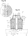
Fig. 1A is a cross-sectional view of the structure of a cartridge in an ion exchanger according to one embodiment. -
Fig. 1B is an enlarged cross-sectional view of section 1B ofFig. 1A . -
Fig. 2A is a cross-sectional view corresponding toFig. 1A , illustrating a state in which a cartridge is in the process of being attached to a case. -
Fig. 2B is a cross-sectional view corresponding toFig. 1A , illustrating a state in which the cartridge is attached to the case. -
Fig. 3A is a cross-sectional view corresponding toFig. 1A , illustrating a state in which a cartridge of a variation is in the process of being attached to a case. -
Fig. 3B is a cross-sectional view corresponding toFig. 1A , illustrating a state in which the cartridge ofFig. 3A is attached to the case. - Throughout the drawings and the detailed description, the same reference numerals refer to the same elements. The drawings may not be to scale, and the relative size, proportions, and depiction of elements in the drawings may be exaggerated for clarity, illustration, and convenience.
- This description provides a comprehensive understanding of the methods, apparatuses, and/or systems described. Modifications and equivalents of the methods, apparatuses, and/or systems described are apparent to one of ordinary skill in the art. Sequences of operations are exemplary, and may be changed as apparent to one of ordinary skill in the art, with the exception of operations necessarily occurring in a certain order. Descriptions of functions and constructions that are well known to one of ordinary skill in the art may be omitted.
- Exemplary embodiments may have different forms, and are not limited to the examples described. However, the examples described are thorough and complete, and convey the full scope of the disclosure to one of ordinary skill in the art.
- An
ion exchanger 10 according to one embodiment will now be described with reference toFigs. 1A to 2B . - As shown in
Fig. 1A , a cooling circuit of a fuel cell includes theion exchanger 10 that removes ions from coolant. - The
ion exchanger 10 includes acase 50 and acartridge 20. Thecase 50 includes a substantiallycylindrical case body 51 having a closed end, and thecase body 51 has an opening 52 open upward. Thecartridge 20 is detachably attached to thecase 50 through the opening 52 and accommodates ion exchange resin R. - The
case 50 includes, at the lower portion, aninflow portion 53, through which coolant flows into thecase body 51, and anoutflow portion 54, through which the coolant flows out of thecase body 51. Athrottle portion 55 connected to theinflow portion 53 and theoutflow portion 54 is arranged between theinflow portion 53 and theoutflow portion 54. - The
cartridge 20 includes a substantiallycylindrical cap 21 having a closed end, where thecap 21 has alower opening 24, and atubular member 30 that is coaxial with thecap 21 inside thecap 21. - The
cap 21 includes a cylindricalcircumferential wall 22 and atop wall 23. Thetop wall 23 includes a first reduceddiameter portion 25 that is cylindrical and reduced in diameter from thecircumferential wall 22 and a second reduceddiameter portion 26 that is upwardly adjacent to the first reduceddiameter portion 25 and further reduced in diameter than the first reduceddiameter portion 25. - As shown in
Figs. 1A and 1B , anexternal thread 27 is provided on the upper portion of the outer circumferential surface of thecircumferential wall 22. Theexternal thread 27 is threaded into aninternal thread 56 provided on the inner circumferential surface of thecase body 51. Theexternal thread 27 of thecap 21 is threaded into theinternal thread 56 of thecase body 51 so that thecartridge 20 is detachably attached to thecase 50. Theexternal thread 27 and theinternal thread 56 form anannular sealing portion 60 that seals a portion between the inner circumferential surface of thecase body 51 and the outer circumferential surface of thecircumferential wall 22 of the cap 21 (cartridge 20). - The
circumferential wall 22 of thecap 21 has adischarge hole 28 at a lower side of theexternal thread 27, more specifically, a portion that is opposed to the inner circumferential surface of thecase body 51 when thecartridge 20 is attached to thecase 50. Thedischarge hole 28 is closed at the radially inner side of thecircumferential wall 22 by aporous member 29 having multiple pores that are smaller than thedischarge hole 28. - The pores of the
porous member 29 have sizes that allow coolant to pass through while not allowing the ion exchange resin R to pass through. - The
tubular member 30 has, at the upper outer circumferential surface, asupport portion 33 includingprojections 34 and anannular portion 35. Theprojections 34 project outward from the upper outer circumferential surface of thetubular member 30 and are spaced apart from each other in the circumferential direction. Theannular portion 35 connects radially outer ends of theprojections 34 together. Theannular portion 35 is joined to the inner circumferential surface of the first reduceddiameter portion 25 of thecap 21. Thetubular member 30 is fixed to thecap 21. The upper end of thetubular member 30 is spaced downward from thetop wall 23. - A first annular
porous body 36 that has a central hole is attached by a gasket (not shown) in a space between the lower outer circumferential surface of thetubular member 30 and the inner circumferential surface of thelower opening 24 of thecap 21. The firstporous body 36 allows coolant to pass through while not allowing the ion exchange resin R to pass through. - A second annular
porous body 37 that has a central hole is attached by a gasket (not shown) in a space between the upper outer circumferential surface of thetubular member 30 and the inner circumferential surface of the first reduceddiameter portion 25 of thecap 21. The secondporous body 37 allows coolant to pass through while not allowing the ion exchange resin R to pass through. The secondporous body 37 is vertically adjacent to thesupport portion 33. - A support member 38 is detachably attached to the
lower opening 24 of thecap 21. The support member 38 includes an inner annular portion 39, projections 40, and an outer annular portion 41. The inner annular portion 39 is fitted onto thetubular member 30. The projections 40 project outward from the inner annular portion 39 and are spaced apart from each other in the circumferential direction. The outer annular portion 41 connects the radially outer ends of the projections 40 together. - In the
cartridge 20, thecircumferential wall 22 of thecap 21, thetubular member 30, the firstporous body 36, and the secondporous body 37 define a toroidal storage space in which the ion exchange resin R is accommodated. - In the
ion exchanger 10, which has the above-described configuration, as shown by arrows inFig. 1A , when coolant flowing in the cooling circuit flows into thecase body 51 from theinflow portion 53, some of the coolant flows through the firstporous body 36, the ion exchange resin R, and the secondporous body 37 in this order and then flows into thetubular member 30 from anupper opening 32. The coolant that has flowed into thetubular member 30 flows downward inside thetubular member 30, is discharged out of thecartridge 20 from alower opening 31, and flows out in theoutflow portion 54. When the coolant passes through the ion exchange resin R, ions in the coolant are exchanged and removed. - An operation of the present embodiment will now be described.
- As shown in
Fig. 2A , when thecartridge 20 is attached to thecase 50, coolant that is present inside thecase body 51 tries to enter thecartridge 20 from the lower portion of thecartridge 20 as shown by a solid-line arrow inFig. 2A . This raises the air pressure of thecartridge 20. - However, as shown by a broken-line arrow in
Fig. 2A , air inside thecartridge 20 is discharged out of thecartridge 20 through thedischarge hole 28 so that the coolant enters thecartridge 20. This restricts rise in the liquid level of the coolant inside thecase body 51 in comparison with a case in which thedischarge hole 28 is not formed (Operation 1). - Further, as shown in
Fig. 2B , thedischarge hole 28 is formed at a lower side of the external thread 27 (sealing portion 60) in thecircumferential wall 22 of thecartridge 20. Thus, when thecartridge 20 is attached to thecase 50, coolant inside thecartridge 20 does not leak out of thecase 50 through the discharge hole 28 (Operation 2). - The advantages of the present embodiment will now be described.
- (1) The
circumferential wall 22 of thecartridge 20 has thedischarge hole 28 at the portion that is opposed to the inner circumferential surface of thecase body 51. Thedischarge hole 28 allows air inside thecartridge 20 to be discharged out of thecartridge 20.
Operation 1 above provided by such a structure prevents coolant from leaking out of thecase 50 when thecartridge 20 is replaced. - (2) The annular
external thread 27 and theinternal thread 56, which form the sealingportion 60, are arranged between the inner circumferential surface of thecase body 51 and the outer circumferential surface of thecircumferential wall 22 of thecartridge 20. Thedischarge hole 28 is formed at the lower side of theexternal thread 27 on thecircumferential wall 22.
Thedischarge hole 28 formed at the upper end such as thetop wall 23 of thecartridge 20 requires an additional member that closes thedischarge hole 28 in order to prevent the ion exchange resin R and coolant from leaking out.
However, Operation 2 provided by the above structure eliminates the necessity of such a member that closes thedischarge hole 28. This simplifies the structure of theion exchanger 10. - (3) The
discharge hole 28 is closed by theporous member 29 having multiple pores that are smaller than thedischarge hole 28. - With such a structure, the
discharge hole 28 is closed by theporous member 29 so that the ion exchange resin R is prevented from leaking out of thedischarge hole 28 even if the size of thedischarge hole 28 is not reduced. This simplifies the structure of thecap 21. - The above-described embodiment may be modified as follows. The above-described embodiment and the following modifications can be combined as long as the combined modifications remain technically consistent with each other.
- Plural discharge holes 28 may be formed.
- The
discharge hole 28 may be replaced with plural pores formed in thecircumferential wall 22 of thecap 21. The pores serve as a discharge hole and have sizes that do not allow the ion exchange resin R to pass through. Such a structure eliminates theporous member 29. - The sealing
portion 60 formed by theinternal thread 56 of thecase body 51 and theexternal thread 27 of thecap 21 may be replaced with a sealing member such as an O-ring that serves as a sealing portion. In this case, a discharge hole may preferably be located below the sealing portion in thecircumferential wall 22 of thecap 21. - As shown in
Figs. 3A and 3B , thedischarge hole 28 may be replaced with adischarge hole 281 that is formed in thetop wall 23 of the cap 21 (cartridge 20). In this case, as shown inFig. 3A , thedischarge hole 281 may be open when thecartridge 20 is attached to thecase 50. Further, as shown inFig. 3B , after thecartridge 20 is attached, thedischarge hole 281 may be closed by acover 282 that is a separate member of thecap 21. Such a structure prevents coolant from leaking out of thecase 50 when thecartridge 20 is replaced and also prevents coolant from leaking out of thedischarge hole 281 when thecartridge 20 is attached to thecase 50. - The
circumferential wall 22 of thecartridge 20 may have a discharge hole at the portion that is opposed to the inner circumferential surface of thecase body 51, and thetop wall 23 of thecartridge 20 may have a discharge hole. - Various changes in form and details may be made to the examples above without departing from the spirit and scope of the claims and their equivalents. The examples are for the sake of description only, and not for purposes of limitation. Descriptions of features in each example are to be considered as being applicable to similar features or aspects in other examples. Suitable results may be achieved if sequences are performed in a different order, and/or if components in a described system, architecture, device, or circuit are combined differently, and/or replaced or supplemented by other components or their equivalents. The scope of the disclosure is not defined by the detailed description, but by the claims and their equivalents. All variations within the scope of the claims and their equivalents are included in the disclosure.
- An ion exchanger includes a case and a cartridge. The case has an opening open upward. The cartridge is detachably attached to the case through the opening and includes a circumferential wall, a top wall, a lower opening, and a porous body. The cartridge accommodates an ion exchange resin. The porous body closes the lower opening of the cartridge and allows coolant to pass through while not allowing the ion exchange resin to pass through. A discharge hole that allows air inside the cartridge to be discharged out of the cartridge is formed in at least one of the top wall of the cartridge or a portion of the circumferential wall of the cartridge that is opposed to the inner circumferential surface of the case body.
Claims (3)
- An ion exchanger comprising:a case (50) including a case body (51) that has an opening (52) open upward and further including, at a lower portion, an inflow portion (53), through which coolant flows into the case body (51), and an outflow portion (54), through which the coolant flows out of the case body (51); anda cartridge (20) detachably attached to the case (50) through the opening (52), wherein the cartridge (20) includes a cap (21), the cap (21) including a circumferential wall (22), a top wall (23) and a lower opening (24), a tubular member (30) that is coaxial with the cap (21) inside the cap (21) and fixed to the cap (21) and a porous body (36) and accommodates an ion exchange resin (R), whereinthe porous body (36) closes the lower opening (24) of the cartridge (20) and allows the coolant to pass through while not allowing the ion exchange resin (R) to pass through, whereinan upper end of the tubular member (30) is spaced downward from the top wall (23), and whereina lower opening (31) of the tubular member (30) is connected to the outflow portion (54),the ion exchanger being characterized in that a discharge hole (28, 281) that allows air inside the cartridge (20) to be discharged out of the cartridge (20) is formed in at least one of the top wall (23) of the cartridge (20) or a portion of the circumferential wall (22) of the cartridge (20) that is opposed to an inner circumferential surface of the case body (51).
- The ion exchanger according to claim 1, characterized in that
an annular sealing portion (60) is arranged between the inner circumferential surface of the case body (51) and an outer circumferential surface of the circumferential wall (22) of the cartridge (20), and
the discharge hole (28) is located below the sealing portion (60) in the circumferential wall (22). - The ion exchanger according to claim 1 or 2, characterized in that the discharge hole (28, 281) is closed by a porous member (29) having multiple pores that are smaller than the discharge hole (28, 281).
Applications Claiming Priority (1)
| Application Number | Priority Date | Filing Date | Title |
|---|---|---|---|
| JP2018232247A JP7139927B2 (en) | 2018-12-12 | 2018-12-12 | ion exchanger |
Publications (2)
| Publication Number | Publication Date |
|---|---|
| EP3666378A1 EP3666378A1 (en) | 2020-06-17 |
| EP3666378B1 true EP3666378B1 (en) | 2021-04-21 |
Family
ID=68771429
Family Applications (1)
| Application Number | Title | Priority Date | Filing Date |
|---|---|---|---|
| EP19213422.9A Active EP3666378B1 (en) | 2018-12-12 | 2019-12-04 | Ion exchanger |
Country Status (4)
| Country | Link |
|---|---|
| US (1) | US11311819B2 (en) |
| EP (1) | EP3666378B1 (en) |
| JP (1) | JP7139927B2 (en) |
| CN (1) | CN111298848B (en) |
Families Citing this family (1)
| Publication number | Priority date | Publication date | Assignee | Title |
|---|---|---|---|---|
| JP7647442B2 (en) * | 2021-08-24 | 2025-03-18 | トヨタ紡織株式会社 | Ion Exchanger |
Family Cites Families (13)
| Publication number | Priority date | Publication date | Assignee | Title |
|---|---|---|---|---|
| US6193689B1 (en) * | 1997-11-19 | 2001-02-27 | Robert W. Woodard | Intravenous liquid flow regulator |
| JP4007725B2 (en) * | 1999-07-15 | 2007-11-14 | オルガノ株式会社 | Cooling water circulation device for fuel cell |
| US6649048B2 (en) * | 2001-11-20 | 2003-11-18 | Stormwater Management | Filter cartridge with regulated surface cleaning mechanism |
| JP4569096B2 (en) * | 2003-11-13 | 2010-10-27 | 日産自動車株式会社 | Fuel cell cooling system |
| US8512555B1 (en) * | 2006-08-23 | 2013-08-20 | Contech Engineered Solutions LLC | Filter assembly, system and method |
| US7396473B1 (en) * | 2007-09-06 | 2008-07-08 | Guynn Stacy D | Engine oil filter |
| US8007948B2 (en) * | 2008-03-14 | 2011-08-30 | GM Global Technology Operations LLC | Ion exchange cartridge for fuel cell applications |
| CA2780159A1 (en) | 2009-08-13 | 2011-02-17 | Mann+Hummel Gmbh | Cooling device for a functional system |
| KR101326509B1 (en) * | 2011-09-06 | 2013-11-08 | 기아자동차주식회사 | Air bubble exhausting device mounted in the ion filter for fuel cell system |
| US20130199986A1 (en) * | 2012-02-03 | 2013-08-08 | Mann+Hummel Gmbh | Ion exchange exoskeleton and filter assembly |
| JP2013233499A (en) * | 2012-05-08 | 2013-11-21 | Toyota Motor Corp | Ion exchanger, and fuel cell system containing the same |
| KR101394795B1 (en) * | 2012-11-01 | 2014-05-15 | 기아자동차주식회사 | Ion filter for fuel cell system |
| JP6579001B2 (en) * | 2016-03-09 | 2019-09-25 | トヨタ紡織株式会社 | Ion exchanger |
-
2018
- 2018-12-12 JP JP2018232247A patent/JP7139927B2/en active Active
-
2019
- 2019-12-02 US US16/700,143 patent/US11311819B2/en active Active
- 2019-12-04 EP EP19213422.9A patent/EP3666378B1/en active Active
- 2019-12-04 CN CN201911225332.9A patent/CN111298848B/en active Active
Also Published As
| Publication number | Publication date |
|---|---|
| CN111298848A (en) | 2020-06-19 |
| CN111298848B (en) | 2023-05-02 |
| US11311819B2 (en) | 2022-04-26 |
| JP2020093212A (en) | 2020-06-18 |
| EP3666378A1 (en) | 2020-06-17 |
| US20200188813A1 (en) | 2020-06-18 |
| JP7139927B2 (en) | 2022-09-21 |
Similar Documents
| Publication | Publication Date | Title |
|---|---|---|
| CN101533919B (en) | Ion exchange cartridge for fuel cell applications | |
| JP6579001B2 (en) | Ion exchanger | |
| US9873066B2 (en) | Ion-exchanger | |
| US9620801B2 (en) | Ion exchanger and cooler having ion exchanger | |
| EP3666378B1 (en) | Ion exchanger | |
| US20130199986A1 (en) | Ion exchange exoskeleton and filter assembly | |
| JP4613125B2 (en) | Ion exchange filter | |
| EP3741440B1 (en) | Filtration device | |
| JP2020021667A (en) | Ion exchanger | |
| CN111630707B (en) | Coolant distribution connection for battery module housing | |
| CN113990551B (en) | Irradiation device and reactor | |
| US20130224617A1 (en) | Coolant Circuit for a Fuel Cell System and Method for Changing out Ion Exchanger Material | |
| CN115175763A (en) | Ion exchanger filter device and ion exchanger box | |
| KR20200094328A (en) | Filter for hydrogen pressure regulation regulator for vehicle | |
| EP4635626A1 (en) | Ion exchanger filter device and ion exchanger cartridge | |
| CN212669205U (en) | Hydrogen production system | |
| JP7092011B2 (en) | Ion exchange resin filling device and ion exchange resin filling method | |
| US20190252083A1 (en) | Cooling water reservoir and passive cooling system comprising same for reactor containment building | |
| CN219267706U (en) | Deionization device for fuel cell | |
| CN207335241U (en) | Drier receiver and on-board air conditioner | |
| CN219778925U (en) | Filtering heat exchange device and flow battery system applicable to same | |
| JP2012161740A (en) | Cartridge housing for ion exchange resin | |
| CN218740527U (en) | Filter equipment, water cooling system and vehicle | |
| JP2025187667A (en) | ion exchanger | |
| CN220125621U (en) | A filtering device for power transformer oil |
Legal Events
| Date | Code | Title | Description |
|---|---|---|---|
| PUAI | Public reference made under article 153(3) epc to a published international application that has entered the european phase |
Free format text: ORIGINAL CODE: 0009012 |
|
| STAA | Information on the status of an ep patent application or granted ep patent |
Free format text: STATUS: REQUEST FOR EXAMINATION WAS MADE |
|
| 17P | Request for examination filed |
Effective date: 20191204 |
|
| AK | Designated contracting states |
Kind code of ref document: A1 Designated state(s): AL AT BE BG CH CY CZ DE DK EE ES FI FR GB GR HR HU IE IS IT LI LT LU LV MC MK MT NL NO PL PT RO RS SE SI SK SM TR |
|
| AX | Request for extension of the european patent |
Extension state: BA ME |
|
| GRAP | Despatch of communication of intention to grant a patent |
Free format text: ORIGINAL CODE: EPIDOSNIGR1 |
|
| STAA | Information on the status of an ep patent application or granted ep patent |
Free format text: STATUS: GRANT OF PATENT IS INTENDED |
|
| RIC1 | Information provided on ipc code assigned before grant |
Ipc: B01J 47/024 20170101AFI20201120BHEP Ipc: H01M 8/04044 20160101ALI20201120BHEP |
|
| INTG | Intention to grant announced |
Effective date: 20201221 |
|
| GRAS | Grant fee paid |
Free format text: ORIGINAL CODE: EPIDOSNIGR3 |
|
| GRAA | (expected) grant |
Free format text: ORIGINAL CODE: 0009210 |
|
| STAA | Information on the status of an ep patent application or granted ep patent |
Free format text: STATUS: THE PATENT HAS BEEN GRANTED |
|
| AK | Designated contracting states |
Kind code of ref document: B1 Designated state(s): AL AT BE BG CH CY CZ DE DK EE ES FI FR GB GR HR HU IE IS IT LI LT LU LV MC MK MT NL NO PL PT RO RS SE SI SK SM TR |
|
| REG | Reference to a national code |
Ref country code: GB Ref legal event code: FG4D |
|
| REG | Reference to a national code |
Ref country code: CH Ref legal event code: EP |
|
| REG | Reference to a national code |
Ref country code: DE Ref legal event code: R096 Ref document number: 602019004077 Country of ref document: DE Ref country code: IE Ref legal event code: FG4D |
|
| REG | Reference to a national code |
Ref country code: AT Ref legal event code: REF Ref document number: 1384058 Country of ref document: AT Kind code of ref document: T Effective date: 20210515 |
|
| REG | Reference to a national code |
Ref country code: LT Ref legal event code: MG9D |
|
| REG | Reference to a national code |
Ref country code: AT Ref legal event code: MK05 Ref document number: 1384058 Country of ref document: AT Kind code of ref document: T Effective date: 20210421 |
|
| REG | Reference to a national code |
Ref country code: NL Ref legal event code: MP Effective date: 20210421 |
|
| PG25 | Lapsed in a contracting state [announced via postgrant information from national office to epo] |
Ref country code: FI Free format text: LAPSE BECAUSE OF FAILURE TO SUBMIT A TRANSLATION OF THE DESCRIPTION OR TO PAY THE FEE WITHIN THE PRESCRIBED TIME-LIMIT Effective date: 20210421 Ref country code: HR Free format text: LAPSE BECAUSE OF FAILURE TO SUBMIT A TRANSLATION OF THE DESCRIPTION OR TO PAY THE FEE WITHIN THE PRESCRIBED TIME-LIMIT Effective date: 20210421 Ref country code: LT Free format text: LAPSE BECAUSE OF FAILURE TO SUBMIT A TRANSLATION OF THE DESCRIPTION OR TO PAY THE FEE WITHIN THE PRESCRIBED TIME-LIMIT Effective date: 20210421 Ref country code: NL Free format text: LAPSE BECAUSE OF FAILURE TO SUBMIT A TRANSLATION OF THE DESCRIPTION OR TO PAY THE FEE WITHIN THE PRESCRIBED TIME-LIMIT Effective date: 20210421 Ref country code: AT Free format text: LAPSE BECAUSE OF FAILURE TO SUBMIT A TRANSLATION OF THE DESCRIPTION OR TO PAY THE FEE WITHIN THE PRESCRIBED TIME-LIMIT Effective date: 20210421 Ref country code: BG Free format text: LAPSE BECAUSE OF FAILURE TO SUBMIT A TRANSLATION OF THE DESCRIPTION OR TO PAY THE FEE WITHIN THE PRESCRIBED TIME-LIMIT Effective date: 20210721 |
|
| PG25 | Lapsed in a contracting state [announced via postgrant information from national office to epo] |
Ref country code: IS Free format text: LAPSE BECAUSE OF FAILURE TO SUBMIT A TRANSLATION OF THE DESCRIPTION OR TO PAY THE FEE WITHIN THE PRESCRIBED TIME-LIMIT Effective date: 20210821 Ref country code: GR Free format text: LAPSE BECAUSE OF FAILURE TO SUBMIT A TRANSLATION OF THE DESCRIPTION OR TO PAY THE FEE WITHIN THE PRESCRIBED TIME-LIMIT Effective date: 20210722 Ref country code: SE Free format text: LAPSE BECAUSE OF FAILURE TO SUBMIT A TRANSLATION OF THE DESCRIPTION OR TO PAY THE FEE WITHIN THE PRESCRIBED TIME-LIMIT Effective date: 20210421 Ref country code: PT Free format text: LAPSE BECAUSE OF FAILURE TO SUBMIT A TRANSLATION OF THE DESCRIPTION OR TO PAY THE FEE WITHIN THE PRESCRIBED TIME-LIMIT Effective date: 20210823 Ref country code: RS Free format text: LAPSE BECAUSE OF FAILURE TO SUBMIT A TRANSLATION OF THE DESCRIPTION OR TO PAY THE FEE WITHIN THE PRESCRIBED TIME-LIMIT Effective date: 20210421 Ref country code: LV Free format text: LAPSE BECAUSE OF FAILURE TO SUBMIT A TRANSLATION OF THE DESCRIPTION OR TO PAY THE FEE WITHIN THE PRESCRIBED TIME-LIMIT Effective date: 20210421 Ref country code: NO Free format text: LAPSE BECAUSE OF FAILURE TO SUBMIT A TRANSLATION OF THE DESCRIPTION OR TO PAY THE FEE WITHIN THE PRESCRIBED TIME-LIMIT Effective date: 20210721 Ref country code: PL Free format text: LAPSE BECAUSE OF FAILURE TO SUBMIT A TRANSLATION OF THE DESCRIPTION OR TO PAY THE FEE WITHIN THE PRESCRIBED TIME-LIMIT Effective date: 20210421 |
|
| REG | Reference to a national code |
Ref country code: DE Ref legal event code: R097 Ref document number: 602019004077 Country of ref document: DE |
|
| PG25 | Lapsed in a contracting state [announced via postgrant information from national office to epo] |
Ref country code: SK Free format text: LAPSE BECAUSE OF FAILURE TO SUBMIT A TRANSLATION OF THE DESCRIPTION OR TO PAY THE FEE WITHIN THE PRESCRIBED TIME-LIMIT Effective date: 20210421 Ref country code: ES Free format text: LAPSE BECAUSE OF FAILURE TO SUBMIT A TRANSLATION OF THE DESCRIPTION OR TO PAY THE FEE WITHIN THE PRESCRIBED TIME-LIMIT Effective date: 20210421 Ref country code: EE Free format text: LAPSE BECAUSE OF FAILURE TO SUBMIT A TRANSLATION OF THE DESCRIPTION OR TO PAY THE FEE WITHIN THE PRESCRIBED TIME-LIMIT Effective date: 20210421 Ref country code: SM Free format text: LAPSE BECAUSE OF FAILURE TO SUBMIT A TRANSLATION OF THE DESCRIPTION OR TO PAY THE FEE WITHIN THE PRESCRIBED TIME-LIMIT Effective date: 20210421 Ref country code: RO Free format text: LAPSE BECAUSE OF FAILURE TO SUBMIT A TRANSLATION OF THE DESCRIPTION OR TO PAY THE FEE WITHIN THE PRESCRIBED TIME-LIMIT Effective date: 20210421 Ref country code: DK Free format text: LAPSE BECAUSE OF FAILURE TO SUBMIT A TRANSLATION OF THE DESCRIPTION OR TO PAY THE FEE WITHIN THE PRESCRIBED TIME-LIMIT Effective date: 20210421 Ref country code: CZ Free format text: LAPSE BECAUSE OF FAILURE TO SUBMIT A TRANSLATION OF THE DESCRIPTION OR TO PAY THE FEE WITHIN THE PRESCRIBED TIME-LIMIT Effective date: 20210421 |
|
| PLBE | No opposition filed within time limit |
Free format text: ORIGINAL CODE: 0009261 |
|
| STAA | Information on the status of an ep patent application or granted ep patent |
Free format text: STATUS: NO OPPOSITION FILED WITHIN TIME LIMIT |
|
| 26N | No opposition filed |
Effective date: 20220124 |
|
| PG25 | Lapsed in a contracting state [announced via postgrant information from national office to epo] |
Ref country code: IS Free format text: LAPSE BECAUSE OF FAILURE TO SUBMIT A TRANSLATION OF THE DESCRIPTION OR TO PAY THE FEE WITHIN THE PRESCRIBED TIME-LIMIT Effective date: 20210821 Ref country code: AL Free format text: LAPSE BECAUSE OF FAILURE TO SUBMIT A TRANSLATION OF THE DESCRIPTION OR TO PAY THE FEE WITHIN THE PRESCRIBED TIME-LIMIT Effective date: 20210421 |
|
| PG25 | Lapsed in a contracting state [announced via postgrant information from national office to epo] |
Ref country code: MC Free format text: LAPSE BECAUSE OF FAILURE TO SUBMIT A TRANSLATION OF THE DESCRIPTION OR TO PAY THE FEE WITHIN THE PRESCRIBED TIME-LIMIT Effective date: 20210421 Ref country code: IT Free format text: LAPSE BECAUSE OF FAILURE TO SUBMIT A TRANSLATION OF THE DESCRIPTION OR TO PAY THE FEE WITHIN THE PRESCRIBED TIME-LIMIT Effective date: 20210421 |
|
| REG | Reference to a national code |
Ref country code: BE Ref legal event code: MM Effective date: 20211231 |
|
| PG25 | Lapsed in a contracting state [announced via postgrant information from national office to epo] |
Ref country code: LU Free format text: LAPSE BECAUSE OF NON-PAYMENT OF DUE FEES Effective date: 20211204 Ref country code: IE Free format text: LAPSE BECAUSE OF NON-PAYMENT OF DUE FEES Effective date: 20211204 |
|
| PG25 | Lapsed in a contracting state [announced via postgrant information from national office to epo] |
Ref country code: FR Free format text: LAPSE BECAUSE OF NON-PAYMENT OF DUE FEES Effective date: 20211231 Ref country code: BE Free format text: LAPSE BECAUSE OF NON-PAYMENT OF DUE FEES Effective date: 20211231 |
|
| PG25 | Lapsed in a contracting state [announced via postgrant information from national office to epo] |
Ref country code: CY Free format text: LAPSE BECAUSE OF FAILURE TO SUBMIT A TRANSLATION OF THE DESCRIPTION OR TO PAY THE FEE WITHIN THE PRESCRIBED TIME-LIMIT Effective date: 20210421 |
|
| PG25 | Lapsed in a contracting state [announced via postgrant information from national office to epo] |
Ref country code: HU Free format text: LAPSE BECAUSE OF FAILURE TO SUBMIT A TRANSLATION OF THE DESCRIPTION OR TO PAY THE FEE WITHIN THE PRESCRIBED TIME-LIMIT; INVALID AB INITIO Effective date: 20191204 |
|
| REG | Reference to a national code |
Ref country code: CH Ref legal event code: PL |
|
| PG25 | Lapsed in a contracting state [announced via postgrant information from national office to epo] |
Ref country code: LI Free format text: LAPSE BECAUSE OF NON-PAYMENT OF DUE FEES Effective date: 20221231 Ref country code: CH Free format text: LAPSE BECAUSE OF NON-PAYMENT OF DUE FEES Effective date: 20221231 |
|
| PG25 | Lapsed in a contracting state [announced via postgrant information from national office to epo] |
Ref country code: MK Free format text: LAPSE BECAUSE OF FAILURE TO SUBMIT A TRANSLATION OF THE DESCRIPTION OR TO PAY THE FEE WITHIN THE PRESCRIBED TIME-LIMIT Effective date: 20210421 |
|
| PG25 | Lapsed in a contracting state [announced via postgrant information from national office to epo] |
Ref country code: TR Free format text: LAPSE BECAUSE OF FAILURE TO SUBMIT A TRANSLATION OF THE DESCRIPTION OR TO PAY THE FEE WITHIN THE PRESCRIBED TIME-LIMIT Effective date: 20210421 |
|
| GBPC | Gb: european patent ceased through non-payment of renewal fee |
Effective date: 20231204 |
|
| PG25 | Lapsed in a contracting state [announced via postgrant information from national office to epo] |
Ref country code: MT Free format text: LAPSE BECAUSE OF FAILURE TO SUBMIT A TRANSLATION OF THE DESCRIPTION OR TO PAY THE FEE WITHIN THE PRESCRIBED TIME-LIMIT Effective date: 20210421 |
|
| PG25 | Lapsed in a contracting state [announced via postgrant information from national office to epo] |
Ref country code: GB Free format text: LAPSE BECAUSE OF NON-PAYMENT OF DUE FEES Effective date: 20231204 |
|
| PG25 | Lapsed in a contracting state [announced via postgrant information from national office to epo] |
Ref country code: GB Free format text: LAPSE BECAUSE OF NON-PAYMENT OF DUE FEES Effective date: 20231204 |
|
| PGFP | Annual fee paid to national office [announced via postgrant information from national office to epo] |
Ref country code: DE Payment date: 20251028 Year of fee payment: 7 |