EP3666201A1 - Aneurysm occluding device for use with coagulating agents - Google Patents
Aneurysm occluding device for use with coagulating agents Download PDFInfo
- Publication number
- EP3666201A1 EP3666201A1 EP19215277.5A EP19215277A EP3666201A1 EP 3666201 A1 EP3666201 A1 EP 3666201A1 EP 19215277 A EP19215277 A EP 19215277A EP 3666201 A1 EP3666201 A1 EP 3666201A1
- Authority
- EP
- European Patent Office
- Prior art keywords
- aneurysm
- channel
- agent
- fan portion
- treatment device
- Prior art date
- Legal status (The legal status is an assumption and is not a legal conclusion. Google has not performed a legal analysis and makes no representation as to the accuracy of the status listed.)
- Withdrawn
Links
- 206010002329 Aneurysm Diseases 0.000 title claims abstract description 188
- 239000000701 coagulant Substances 0.000 title claims abstract description 90
- 239000003795 chemical substances by application Substances 0.000 claims abstract description 86
- 238000002347 injection Methods 0.000 claims abstract description 9
- 239000007924 injection Substances 0.000 claims abstract description 9
- 238000011282 treatment Methods 0.000 claims description 84
- 238000000034 method Methods 0.000 claims description 42
- 238000000605 extraction Methods 0.000 claims description 23
- 210000004204 blood vessel Anatomy 0.000 claims description 20
- 230000007246 mechanism Effects 0.000 claims description 20
- 230000004888 barrier function Effects 0.000 claims description 13
- 239000008280 blood Substances 0.000 claims description 10
- 210000004369 blood Anatomy 0.000 claims description 10
- 238000004891 communication Methods 0.000 claims description 9
- 230000014759 maintenance of location Effects 0.000 claims 1
- 230000015271 coagulation Effects 0.000 abstract description 3
- 238000005345 coagulation Methods 0.000 abstract description 3
- 239000000463 material Substances 0.000 description 13
- 238000010586 diagram Methods 0.000 description 8
- 230000017531 blood circulation Effects 0.000 description 7
- 230000003073 embolic effect Effects 0.000 description 6
- 238000013459 approach Methods 0.000 description 4
- 239000003814 drug Substances 0.000 description 4
- 229940079593 drug Drugs 0.000 description 4
- 230000003213 activating effect Effects 0.000 description 3
- 150000001875 compounds Chemical class 0.000 description 3
- 230000006870 function Effects 0.000 description 3
- 239000002245 particle Substances 0.000 description 3
- 238000012986 modification Methods 0.000 description 2
- 230000004048 modification Effects 0.000 description 2
- HLXZNVUGXRDIFK-UHFFFAOYSA-N nickel titanium Chemical compound [Ti].[Ti].[Ti].[Ti].[Ti].[Ti].[Ti].[Ti].[Ti].[Ti].[Ti].[Ni].[Ni].[Ni].[Ni].[Ni].[Ni].[Ni].[Ni].[Ni].[Ni].[Ni].[Ni].[Ni].[Ni] HLXZNVUGXRDIFK-UHFFFAOYSA-N 0.000 description 2
- 229910001000 nickel titanium Inorganic materials 0.000 description 2
- 238000012856 packing Methods 0.000 description 2
- 238000001356 surgical procedure Methods 0.000 description 2
- 238000002560 therapeutic procedure Methods 0.000 description 2
- 230000001732 thrombotic effect Effects 0.000 description 2
- 238000012546 transfer Methods 0.000 description 2
- 210000005166 vasculature Anatomy 0.000 description 2
- 239000005995 Aluminium silicate Substances 0.000 description 1
- 229920001661 Chitosan Polymers 0.000 description 1
- 206010053567 Coagulopathies Diseases 0.000 description 1
- 102000008186 Collagen Human genes 0.000 description 1
- 108010035532 Collagen Proteins 0.000 description 1
- 238000012276 Endovascular treatment Methods 0.000 description 1
- FAPWRFPIFSIZLT-UHFFFAOYSA-M Sodium chloride Chemical compound [Na+].[Cl-] FAPWRFPIFSIZLT-UHFFFAOYSA-M 0.000 description 1
- 208000007536 Thrombosis Diseases 0.000 description 1
- 229930003448 Vitamin K Natural products 0.000 description 1
- 229910021536 Zeolite Inorganic materials 0.000 description 1
- 229910045601 alloy Inorganic materials 0.000 description 1
- 239000000956 alloy Substances 0.000 description 1
- 235000012211 aluminium silicate Nutrition 0.000 description 1
- 238000013176 antiplatelet therapy Methods 0.000 description 1
- 230000008321 arterial blood flow Effects 0.000 description 1
- 230000004872 arterial blood pressure Effects 0.000 description 1
- 230000023555 blood coagulation Effects 0.000 description 1
- 238000009954 braiding Methods 0.000 description 1
- 210000004556 brain Anatomy 0.000 description 1
- 210000005013 brain tissue Anatomy 0.000 description 1
- 230000035602 clotting Effects 0.000 description 1
- 230000001112 coagulating effect Effects 0.000 description 1
- 229920001436 collagen Polymers 0.000 description 1
- 238000005056 compaction Methods 0.000 description 1
- 230000006835 compression Effects 0.000 description 1
- 238000007906 compression Methods 0.000 description 1
- HNPSIPDUKPIQMN-UHFFFAOYSA-N dioxosilane;oxo(oxoalumanyloxy)alumane Chemical compound O=[Si]=O.O=[Al]O[Al]=O HNPSIPDUKPIQMN-UHFFFAOYSA-N 0.000 description 1
- 238000011977 dual antiplatelet therapy Methods 0.000 description 1
- 230000000694 effects Effects 0.000 description 1
- 238000005516 engineering process Methods 0.000 description 1
- 210000001105 femoral artery Anatomy 0.000 description 1
- 210000004013 groin Anatomy 0.000 description 1
- 230000035876 healing Effects 0.000 description 1
- 238000002513 implantation Methods 0.000 description 1
- 238000000338 in vitro Methods 0.000 description 1
- 230000002401 inhibitory effect Effects 0.000 description 1
- NLYAJNPCOHFWQQ-UHFFFAOYSA-N kaolin Chemical compound O.O.O=[Al]O[Si](=O)O[Si](=O)O[Al]=O NLYAJNPCOHFWQQ-UHFFFAOYSA-N 0.000 description 1
- 238000009940 knitting Methods 0.000 description 1
- 239000000203 mixture Substances 0.000 description 1
- 210000005036 nerve Anatomy 0.000 description 1
- SHUZOJHMOBOZST-UHFFFAOYSA-N phylloquinone Natural products CC(C)CCCCC(C)CCC(C)CCCC(=CCC1=C(C)C(=O)c2ccccc2C1=O)C SHUZOJHMOBOZST-UHFFFAOYSA-N 0.000 description 1
- 229920000642 polymer Polymers 0.000 description 1
- 229920002635 polyurethane Polymers 0.000 description 1
- 239000004814 polyurethane Substances 0.000 description 1
- 238000011084 recovery Methods 0.000 description 1
- 229910052710 silicon Inorganic materials 0.000 description 1
- 239000010703 silicon Substances 0.000 description 1
- 239000011780 sodium chloride Substances 0.000 description 1
- 239000000243 solution Substances 0.000 description 1
- 238000012360 testing method Methods 0.000 description 1
- 235000019168 vitamin K Nutrition 0.000 description 1
- 239000011712 vitamin K Substances 0.000 description 1
- 150000003721 vitamin K derivatives Chemical class 0.000 description 1
- 229940046010 vitamin k Drugs 0.000 description 1
- 238000009941 weaving Methods 0.000 description 1
- 239000010457 zeolite Substances 0.000 description 1
Images










Classifications
-
- A—HUMAN NECESSITIES
- A61—MEDICAL OR VETERINARY SCIENCE; HYGIENE
- A61B—DIAGNOSIS; SURGERY; IDENTIFICATION
- A61B17/00—Surgical instruments, devices or methods
- A61B17/12—Surgical instruments, devices or methods for ligaturing or otherwise compressing tubular parts of the body, e.g. blood vessels or umbilical cord
- A61B17/12022—Occluding by internal devices, e.g. balloons or releasable wires
- A61B17/12099—Occluding by internal devices, e.g. balloons or releasable wires characterised by the location of the occluder
- A61B17/12109—Occluding by internal devices, e.g. balloons or releasable wires characterised by the location of the occluder in a blood vessel
- A61B17/12113—Occluding by internal devices, e.g. balloons or releasable wires characterised by the location of the occluder in a blood vessel within an aneurysm
-
- A—HUMAN NECESSITIES
- A61—MEDICAL OR VETERINARY SCIENCE; HYGIENE
- A61B—DIAGNOSIS; SURGERY; IDENTIFICATION
- A61B17/00—Surgical instruments, devices or methods
- A61B17/12—Surgical instruments, devices or methods for ligaturing or otherwise compressing tubular parts of the body, e.g. blood vessels or umbilical cord
- A61B17/12022—Occluding by internal devices, e.g. balloons or releasable wires
- A61B17/12027—Type of occlusion
- A61B17/12031—Type of occlusion complete occlusion
-
- A—HUMAN NECESSITIES
- A61—MEDICAL OR VETERINARY SCIENCE; HYGIENE
- A61B—DIAGNOSIS; SURGERY; IDENTIFICATION
- A61B17/00—Surgical instruments, devices or methods
- A61B17/12—Surgical instruments, devices or methods for ligaturing or otherwise compressing tubular parts of the body, e.g. blood vessels or umbilical cord
- A61B17/12022—Occluding by internal devices, e.g. balloons or releasable wires
- A61B17/12131—Occluding by internal devices, e.g. balloons or releasable wires characterised by the type of occluding device
- A61B17/12136—Balloons
-
- A—HUMAN NECESSITIES
- A61—MEDICAL OR VETERINARY SCIENCE; HYGIENE
- A61B—DIAGNOSIS; SURGERY; IDENTIFICATION
- A61B17/00—Surgical instruments, devices or methods
- A61B17/12—Surgical instruments, devices or methods for ligaturing or otherwise compressing tubular parts of the body, e.g. blood vessels or umbilical cord
- A61B17/12022—Occluding by internal devices, e.g. balloons or releasable wires
- A61B17/12131—Occluding by internal devices, e.g. balloons or releasable wires characterised by the type of occluding device
- A61B17/1214—Coils or wires
- A61B17/1215—Coils or wires comprising additional materials, e.g. thrombogenic, having filaments, having fibers, being coated
-
- A—HUMAN NECESSITIES
- A61—MEDICAL OR VETERINARY SCIENCE; HYGIENE
- A61B—DIAGNOSIS; SURGERY; IDENTIFICATION
- A61B17/00—Surgical instruments, devices or methods
- A61B17/12—Surgical instruments, devices or methods for ligaturing or otherwise compressing tubular parts of the body, e.g. blood vessels or umbilical cord
- A61B17/12022—Occluding by internal devices, e.g. balloons or releasable wires
- A61B17/12131—Occluding by internal devices, e.g. balloons or releasable wires characterised by the type of occluding device
- A61B17/12181—Occluding by internal devices, e.g. balloons or releasable wires characterised by the type of occluding device formed by fluidized, gelatinous or cellular remodelable materials, e.g. embolic liquids, foams or extracellular matrices
-
- A—HUMAN NECESSITIES
- A61—MEDICAL OR VETERINARY SCIENCE; HYGIENE
- A61B—DIAGNOSIS; SURGERY; IDENTIFICATION
- A61B17/00—Surgical instruments, devices or methods
- A61B17/12—Surgical instruments, devices or methods for ligaturing or otherwise compressing tubular parts of the body, e.g. blood vessels or umbilical cord
- A61B17/12022—Occluding by internal devices, e.g. balloons or releasable wires
- A61B17/12131—Occluding by internal devices, e.g. balloons or releasable wires characterised by the type of occluding device
- A61B17/12181—Occluding by internal devices, e.g. balloons or releasable wires characterised by the type of occluding device formed by fluidized, gelatinous or cellular remodelable materials, e.g. embolic liquids, foams or extracellular matrices
- A61B17/12186—Occluding by internal devices, e.g. balloons or releasable wires characterised by the type of occluding device formed by fluidized, gelatinous or cellular remodelable materials, e.g. embolic liquids, foams or extracellular matrices liquid materials adapted to be injected
-
- A—HUMAN NECESSITIES
- A61—MEDICAL OR VETERINARY SCIENCE; HYGIENE
- A61B—DIAGNOSIS; SURGERY; IDENTIFICATION
- A61B17/00—Surgical instruments, devices or methods
- A61B17/12—Surgical instruments, devices or methods for ligaturing or otherwise compressing tubular parts of the body, e.g. blood vessels or umbilical cord
- A61B17/12022—Occluding by internal devices, e.g. balloons or releasable wires
- A61B17/12131—Occluding by internal devices, e.g. balloons or releasable wires characterised by the type of occluding device
- A61B17/12181—Occluding by internal devices, e.g. balloons or releasable wires characterised by the type of occluding device formed by fluidized, gelatinous or cellular remodelable materials, e.g. embolic liquids, foams or extracellular matrices
- A61B17/12195—Occluding by internal devices, e.g. balloons or releasable wires characterised by the type of occluding device formed by fluidized, gelatinous or cellular remodelable materials, e.g. embolic liquids, foams or extracellular matrices comprising a curable material
-
- A—HUMAN NECESSITIES
- A61—MEDICAL OR VETERINARY SCIENCE; HYGIENE
- A61M—DEVICES FOR INTRODUCING MEDIA INTO, OR ONTO, THE BODY; DEVICES FOR TRANSDUCING BODY MEDIA OR FOR TAKING MEDIA FROM THE BODY; DEVICES FOR PRODUCING OR ENDING SLEEP OR STUPOR
- A61M25/00—Catheters; Hollow probes
- A61M25/0067—Catheters; Hollow probes characterised by the distal end, e.g. tips
- A61M25/0082—Catheter tip comprising a tool
-
- A—HUMAN NECESSITIES
- A61—MEDICAL OR VETERINARY SCIENCE; HYGIENE
- A61B—DIAGNOSIS; SURGERY; IDENTIFICATION
- A61B17/00—Surgical instruments, devices or methods
- A61B2017/00743—Type of operation; Specification of treatment sites
- A61B2017/00778—Operations on blood vessels
-
- A—HUMAN NECESSITIES
- A61—MEDICAL OR VETERINARY SCIENCE; HYGIENE
- A61B—DIAGNOSIS; SURGERY; IDENTIFICATION
- A61B17/00—Surgical instruments, devices or methods
- A61B2017/00831—Material properties
- A61B2017/00867—Material properties shape memory effect
-
- A—HUMAN NECESSITIES
- A61—MEDICAL OR VETERINARY SCIENCE; HYGIENE
- A61B—DIAGNOSIS; SURGERY; IDENTIFICATION
- A61B17/00—Surgical instruments, devices or methods
- A61B2017/00831—Material properties
- A61B2017/00867—Material properties shape memory effect
- A61B2017/00871—Material properties shape memory effect polymeric
-
- A—HUMAN NECESSITIES
- A61—MEDICAL OR VETERINARY SCIENCE; HYGIENE
- A61B—DIAGNOSIS; SURGERY; IDENTIFICATION
- A61B17/00—Surgical instruments, devices or methods
- A61B2017/00831—Material properties
- A61B2017/00893—Material properties pharmaceutically effective
-
- A—HUMAN NECESSITIES
- A61—MEDICAL OR VETERINARY SCIENCE; HYGIENE
- A61B—DIAGNOSIS; SURGERY; IDENTIFICATION
- A61B17/00—Surgical instruments, devices or methods
- A61B17/12—Surgical instruments, devices or methods for ligaturing or otherwise compressing tubular parts of the body, e.g. blood vessels or umbilical cord
- A61B17/12022—Occluding by internal devices, e.g. balloons or releasable wires
- A61B2017/1205—Introduction devices
Definitions
- the present invention generally relates to medical instruments, and more particularly, to treatment devices for aneurysm therapy.
- Aneurysms can be complicated and difficult to treat. For example, treatment access can be limited or unavailable when an aneurysm is located proximate critical tissues. Such factors are of particular concern with cranial aneurysms due to the brain tissue surrounding cranial vessels and the corresponding limited treatment access.
- occlusive devices can include occlusive devices.
- Such devices have typically incorporated multiple embolic coils that are delivered to the vasculature using microcatheter delivery systems.
- embolic coils are delivered to the vasculature using microcatheter delivery systems.
- a delivery catheter with embolic coils is typically first inserted into non-cranial vasculature through a femoral artery in the hip or groin area. Thereafter, the catheter is guided to a location of interest within the cranium. The sac of the aneurysm can then be filled with the embolic material to create a thrombotic mass that protects the arterial walls from blood flow and related pressure.
- embolic coil packing density sufficient to either occlude the aneurysm neck or fill the aneurysm sac is difficult and time consuming.
- aneurysm morphology e.g. wide neck, bifurcation, etc.
- ancillary devices such as stents or balloons to support the coil mass and obtain the desired packing density.
- the coils and accompanying ancillary devices can remain in patients for their entire lives.
- embolic coils do not always effectively treat aneurysms as re-canalization of the aneurysm and/or coil compaction can occur over time. Many people who undergo aneurysm coil procedures also require a long period of dual antiplatelet therapy while the patient recovers post-procedure.
- One particular type of occlusive approach endeavors to deliver and treat the entrance or "neck" of the aneurysm as opposed to the volume of the aneurysm by implanting a device in the parent vessel of the aneurysm.
- neck approaches, by minimizing blood flow across the neck, a cessation of flow into the aneurysm can be achieved.
- a thrombotic mass can naturally form without having to deliver embolic materials into the aneurysm sac, as previously described.
- this approach also has its drawbacks, as the aneurysm does not undergo thromboses immediately, and there is still a risk of rupture post-surgery. Therefore, there is a need for a device capable of simplified and shortened implantation procedures that can quickly inhibit blood flow in an aneurysm to increase patient safety, reduce the length of the patient recovery period, and reduce the length of antiplatelet therapy administration.
- the devices can generally include a fan portion for occluding an aneurysm neck, a channel orifice opening in the fan portion, and an agent channel for delivering a coagulating agent through the orifice into the aneurysm.
- Devices can be delivered through a catheter to the aneurysm, the fan portion can expand to occlude the aneurysm neck, and the coagulating agent can be injected into the aneurysm.
- the fan portion can create a barrier to inhibit the coagulating agent from exiting the aneurysm.
- the fan portion can collapse and the device can be extracted from the patient.
- An example device for occluding an aneurysm can include a fan portion that is expandable from a collapsed configuration to an occluding configuration, a channel orifice, and an agent channel.
- the fan portion in the occluding configuration can occlude an aneurysm neck to create a barrier between the aneurysm and a blood vessel. This barrier can prevent the coagulating agent from leaking into the blood vessel during and/or after delivery of the agent into the aneurysm sac.
- the fan portion can extend across and occlude at least a portion of the aneurysm neck or can completely occlude the aneurysm neck in the occluding configuration.
- the channel orifice can define an opening in the fan portion through which the coagulating agent can be injected.
- the agent channel can be in communication with the channel orifice and can deliver the coagulating agent through the channel orifice into the aneurysm sac.
- the example device can be delivered to the aneurysm using a microcatheter.
- the fan portion can detach from its position near the aneurysm neck after the coagulating agent has been delivered to the aneurysm sac.
- the fan portion can be collapsed from the occluding configuration to an extraction configuration. This extraction configuration can be sized to fit inside a retrieval catheter.
- the fan portion can consist of at least one elongated support.
- the elongated support can be connected to an occluding element.
- the elongated support can have a first end and a second end. The first end of the elongated support can be positioned near the channel orifice in the fan portion.
- the second end of the elongated support can extend towards a wall of the aneurysm across at least a portion of the aneurysm neck to occlude the neck when the fan portion is expanded to the occluding configuration.
- the fan portion can also be inflated to reach the occluding configuration.
- the device can include an inflation tube to inflate the fan portion to the occluding configuration.
- the inflation tube can have a distal end connected to the fan portion.
- the agent channel can have a proximal end and a distal end.
- the distal end of the agent channel can communicate with the channel orifice to transfer the coagulating agent into the aneurysm sac.
- the proximal end of the agent channel can receive the coagulating agent.
- the channel orifice can also be an opening in the distal end of the agent channel, whereby a single opening functions as both the channel orifice and the distal end of the agent channel.
- the example device can further have a trigger mechanism in communication with the proximal end of the agent channel.
- the trigger mechanism can communicate with the proximal end of the agent channel to receive the coagulating agent or introduce the coagulating agent into the agent channel.
- the trigger mechanism can facilitate delivery of the coagulating agent from the proximal end to the distal end of the agent channel, and then through the channel orifice into the aneurysm sac.
- a delivery apparatus for treating an aneurysm can have an agent channel that can deliver a coagulating agent to an aneurysm sac.
- the agent channel can have a distal end and a proximal end.
- the proximal end of the agent channel can receive the coagulating agent and deliver the coagulating agent from the proximal end to the distal end of the agent channel.
- the distal end of the agent channel can communicate with a channel orifice in a fan portion and deliver the coagulating agent through the channel orifice into the aneurysm.
- the channel orifice can also be an opening in the distal end of the agent channel.
- the fan portion can expand from a collapsed configuration to an occluding configuration.
- the fan portion in the occluding configuration can extend across and occlude a portion of an aneurysm neck to create a barrier between a blood vessel and the aneurysm. This barrier can prevent the delivered coagulating agent from entering the blood vessel and help retain the coagulating agent inside the aneurysm sac.
- the fan portion can detach from its position near the aneurysm neck after the coagulating agent has been delivered to the aneurysm sac.
- the fan portion can collapse from the occluding configuration to an extraction configuration.
- This extraction configuration can be sized to fit inside a retrieval catheter.
- the example apparatus can further comprise a trigger mechanism in communication with the proximal end of the agent channel for receiving the coagulating agent or introducing the coagulating agent into the agent channel.
- An example method for treating an aneurysm can include providing an exemplary treatment device which can include a fan portion, a channel orifice defining an opening in the fan portion, and an agent channel; joining the agent channel to the channel orifice; delivering the exemplary treatment device to an aneurysm treatment site; expanding the fan portion to an occluding configuration approximate a center of an aneurysm neck wherein the expanded fan portion occludes at least a portion of the aneurysm neck; injecting a coagulating agent through the agent channel, through the channel orifice, and into the aneurysm sac to coagulate the blood present in the aneurysm; and collapsing the treatment device from the occluding configuration to an extraction configuration for extraction of the device after the injection of the coagulating agent.
- the method can include the step of creating a barrier with the fan portion between a blood vessel and the aneurysm to prevent the coagulating agent from entering the blood vessel.
- the method can include removing the treatment device through a microcatheter or through a retrieval deployment system.
- the method can include treating an aneurysm with only a single implementation step.
- the method can further include providing a trigger mechanism and triggering the delivery of the agent by activating the trigger mechanism at a proximal end of the agent channel to deliver the agent from the proximal end of the agent channel to a distal end of the agent channel.
- example devices described herein describe a treatment device that can be placed over the neck of an aneurysm to create a barrier between a vessel and the aneurysm. At least one coagulating agent can then delivered into the aneurysm sac. Delivery can be activated via trigger mechanism on the proximal end of the delivery system. The device can be held approximate the aneurysm neck at least until the coagulating agent is injected, and then can be retracted or detached from the aneurysm. The rapid coagulating agents can coagulate the blood in the aneurysm instantly. In some examples, the device can be removed via a microcatheter or deployed via a retrieval deployment system.
- the example devices can include a fan portion that can expand from a collapsed configuration to an occluding configuration in which the fan portion in the occluding configuration is shaped to occlude an aneurysm neck from within an aneurysm sac.
- the fan portion can generally have a channel orifice working in connection with an agent channel that delivers a coagulating agent through the channel orifice and into the aneurysm sac.
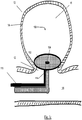
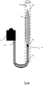
- FIG. 1 an example treatment device 100 is shown with the fan portion 102 in an occluding configuration approximate the neck 12 of an aneurysm 10.
- the fan portion 102 can occlude the aneurysm 10 from inside the aneurysm sac 16.
- the fan portion 102 in the occluding configuration can be sized to occlude at least a portion of the aneurysm neck 12.
- the fan portion 102 in the occluding configuration can completely occlude the aneurysm neck 12 as depicted in FIG. 1 .
- the fan portion 102 in the occluding configuration can occlude the neck 12 to create a barrier between a blood vessel 106 and the aneurysm 10.
- the fan portion 102 can contain a channel orifice 104. As illustrated, the channel orifice 104 can be located in the fan portion 102 such that the channel orifice 104 opens up to the aneurysm 10. The channel orifice 104 can be centrally located in the fan portion 102. The channel orifice can work in connection with an agent channel 112.
- FIGs. 2a through 2f are illustrations of stages or steps that can occur during a treatment sequence of an exemplary treatment device 100 and delivery of a coagulating agent 114 to an aneurysm 10.
- the coagulating agent 114 can be a drug based on replacement factors, vitamin K, antiplasmins or any other drugs known to those of skill in the art that can affect blood clotting.
- a rapidly clotting drug can be effective.
- the drug needs to be deliverable through a torturous agent channel 112.
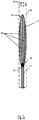
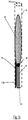
- FIG. 2a is an illustration of an example treatment device 100 wherein the fan portion 102 is shown in a collapsed delivery configuration inside a delivery catheter 400, a channel orifice 104 positioned on a proximal end of the collapsed fan portion 102, and an agent channel 112 attached to the channel orifice 104.
- the fan portion 102 can be sized to fit within the lumen of a delivery catheter 400 when the fan portion 102 is in the collapsed configuration.
- the treatment device 100 in its entirety can be sized to fit within the lumen of a delivery catheter 400 when the fan portion 102 is in the collapsed configuration.
- the fan portion 102 When the fan portion 102 is in the collapsed configuration, the fan portion 102 can have sufficient flexibility to be delivered through the delivery catheter 400, navigating torturous anatomical geometries, to be delivered to an aneurysm 10 (not shown).
- the agent channel 112 can have sufficient length to be accessible outside of the patient when the fan portion 102 reaches a treatment site.
- the fan portion 102 in the collapsed configuration can have a substantially tubular shape.
- the fan portion 102 can be comprised of at least one elongated support 108.
- the example in FIG. 2a shows three elongated supports 108 comprising the fan portion 102.
- An occluding element 110 can be attached to the one or more elongated supports 108.
- the treatment device 100 can be delivered to an aneurysm 10 by sliding the device 100 distally when the fan portion 102 is in a collapsed configuration through a delivery catheter 400.
- the treatment device 100 can be delivered to a treatment site through a blood vessel 106.
- FIG. 2b illustrates the treatment device 100 inside the delivery catheter 400 located near an aneurysm neck 12.
- FIG. 2b further shows the fan portion 102 pushed partially out of the delivery catheter 400 for deployment inside the aneurysm sac 16.
- the fan portion 102 can expand as it exits the delivery catheter 400.
- the fan portion 102 can include a memory shape material such as Nitinol, a Nitinol alloy, a polymer memory shape material, or other memory shape material having properties for reshaping as described herein.
- the fan portion 102 can be in a deformed shape in the collapsed configuration and reshape based on a predetermined shape after exiting the delivery catheter 400.
- each elongated support 108 of the fan portion 102 can have a first end 108a positioned approximate the channel orifice 104, and a second end 108b extending from the first end 108a across at least a portion of the aneurysm neck 12 towards an aneurysm wall 14.
- the second end 108b can extend towards the interior wall 14 of the aneurysm 10 upon expansion of the fan portion 102.
- the elongated support 108 can in turn expand the connected occluding element 110 to occlude at least a portion of the aneurysm neck 12.
- the occluding element 110 can expand upon discharge from the delivery catheter 400 and cause the second end 108b of each connected elongated support 108 to move towards the aneurysm wall 14.
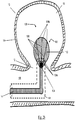
- FIG. 2c illustrates the example treatment device 100 wherein the fan portion 102 is in an occluding configuration in the aneurysm 10.
- the fan portion 102 in the occluding configuration can be sized to occlude at least a portion of an aneurysm neck 12.
- the fan portion 102 in the occluding configuration can completely occlude the aneurysm neck 12 as depicted in FIG. 2c .
- the fan portion 102 in the occluding configuration can occlude the neck 12 to create a barrier between a blood vessel 106 and the aneurysm 10. As illustrated in FIG.
- the second end 108b of the elongated support 108 can be in contact with the aneurysm wall 14 when the fan portion 102 is in the occluding configuration.
- the fan portion 102 can be capable of deflecting a blood flow from the aneurysm 10, diverting a blood flow from the aneurysm 10, slowing a blood flow into the aneurysm 10, or any combination thereof.
- the fan portion 102 can extend to the aneurysm wall 14, and the fan portion 102 can provide a force against the aneurysm wall 14 to maintain the expanded position of the fan portion 102 such that the treatment device 100 doesn't become dislodged and become ineffective at inhibiting blood flow into the aneurysm.
- the force of the fan portion 102 to the aneurysm wall 14 can be sufficient to maintain the position of the treatment device 100 within the aneurysm 10.
- the fan portion 102 can be made of a memory shape material having a first, predetermined shape and a second, collapsed shape in the collapsed configuration.
- the fan portion 102 When the fan portion 102 is in an occluding configuration within the aneurysm 10, the fan portion 102 can move to a third, deployed shape that is based at least in part on the first, predetermined shape and the anatomical geometry of the aneurysm 10.
- the first, predetermined shape can be sized larger than the wall 14 within the aneurysm sac 16; the fan portion 102 can move to extend to the wall 14; and the fan portion 102 can provide a force against the wall 14 as the properties of the memory shape material cause the fan portion 102 to attempt to open to the predetermined shape.
- the fan portion 102 in the occluding configuration can take the shape of the aneurysm neck 12 and/or interior walls 14 of the aneurysm near the aneurysm neck 12.
- FIG. 2d is an illustration of a cross-sectional view looking distally into the aneurysm 10 of an example treatment device 100 where the fan portion 102 is in the occluding configuration, such as the treatment device 100 depicted in FIG. 2c .
- FIG. 2e illustrates the treatment device 100 wherein the fan portion 102 is in the occluding configuration.
- the channel orifice 104 in the fan portion 102 can work in connection with an agent channel 112.
- the agent channel 112 can allow for the transfer of one or more coagulating agents 114 through the channel 112 to the channel orifice 104.
- the coagulating agent 114 can include rapid coagulating agents, such as collagen, chitosan, kaolin, zeolite, or other agents having properties for coagulating as described herein.
- the agent channel 112 can have a distal end 112a a proximal end (not shown). The distal end 112a of the agent channel 112 can connect to the channel orifice 104.
- the proximal end can receive the coagulating agent 114 into the agent channel 112 and deliver the coagulating agent 114 from the proximal end to the distal end 112a connected to the channel orifice 104.
- the proximal end can be accessible outside of the patient for injection of the coagulating agent 114 into the patient.
- Coagulating agent 114 passing through the lumen of the agent channel 112 to the distal end 112a can subsequently pass through the channel orifice 104 and into the aneurysm sac 16 upon reaching the distal end 112a of the agent channel 112.
- the distal end 112a of the agent channel 112 can also be the channel orifice 104 of the fan portion 102.
- the coagulating agent 114 can coagulate the blood inside the aneurysm 10.
- the coagulating agent 114 can coagulate the blood inside the aneurysm 10 virtually instantaneously upon contacting the blood inside the aneurysm 10 according to the coagulation properties of the coagulating agent 114.
- the treatment device 100 can be removed from the aneurysm 10.
- the treatment device 100 can be removed once the coagulating agent 114 has coagulated the blood in the aneurysm 10.
- the treatment device 100 can detach from its location approximate the aneurysm neck 12 after delivery of the coagulating agent 114.
- the occluding element 110, the elongated supports 108, or both the occluding element 110 and the elongated supports 108 can detach from their location approximate the aneurysm neck 12 after delivery of the coagulating agent 114.
- the treatment device 100 can be removed via a retrieval deployment system.
- the fan portion 102 (not shown) can collapse from the occluding configuration to an extraction configuration after the coagulating agent 114 has been delivered to the aneurysm sac 16.
- the extraction configuration can be sized to traverse through a lumen of a catheter (not shown).
- the aneurysm 10, now filled with the coagulating agent 114 can now start to be reabsorbed into the blood vessel 106 through the body's natural healing process. This can avoid the need for permanently implanted elements in the patient.
- FIGs. 3a to 3e are illustrations of stages or steps that can occur during another example implementation sequence of an exemplary treatment device 100.
- FIG. 3a illustrates an example treatment device 100 comprising a fan portion 102 having a channel orifice 104, an agent channel 112 connected to the channel orifice 104 at a distal end 112a of the agent channel 112, and an inflation tube 118 connected to the fan portion 102.
- the fan portion 102 is shown in a collapsed delivery configuration inside a delivery catheter 400.
- the fan portion 102 can be in connection with the inflation tube 118 which can inflate the fan portion 102.
- the fan portion 102 can include at least one material used in neurovascular balloons, such as polyurethane or silicon.
- the inflation tube 118 can have a distal end 118a connected to the fan portion 102.
- FIG. 3b illustrates the treatment device 100 inside the delivery catheter 400 with the fan portion 102 exiting the delivery catheter 104 for deployment inside a sac 16 of an aneurysm 10.
- the fan portion 102 can be inflated to expand using the inflation tube 118 as it exits the delivery catheter 400.
- the fan portion 102 can be completely removed from the delivery catheter 400 before inflation begins.
- inflation of the fan portion 102 can begin while the fan portion 102 is still entirely or partially inside the delivery catheter 400.
- Inflation of the fan portion 102 can occur using saline or a variety of other elements known in the art with respect to inflating neurovascular balloons.
- the outer surface of the fan portion 102 can expand towards the aneurysm wall 14.
- FIG. 3c illustrates the treatment device 100 wherein the fan portion 102 is in an occluding configuration in the aneurysm 10. As illustrated in FIG. 3c , fan portion 102 can inflate to the extent that the fan portion 102 can be in contact with the aneurysm wall 14 when the fan portion 102 is in the occluding configuration. FIG. 3c illustrates the delivery of a coagulating agent 114 to the aneurysm sac 16 in the same manner as described in FIG. 2e .
- FIG. 3d illustrates coagulation agent 114 delivered into the aneurysm sac 16 and a retrieval catheter 500 in place to extract the device 100.
- the fan portion 102 can collapse from the occluding configuration to an extraction configuration after the coagulating agent 114 has been delivered to the aneurysm sac 16.
- the extraction configuration can be sized to traverse through a lumen of the retrieval catheter 500.
- the treatment device 100 can be extracted using the retrieval catheter 500 or a deployment and retrieval device.
- the delivery catheter 400 can also be the retrieval catheter 500.
- FIG. 3e illustrates the aneurysm following extraction of the retrieval catheter 500 and the treatment device 100.
- the fan portion 102 can detach from its location approximate the aneurysm neck 12.
- the fan portion 102 can deflate from the occluding configuration to an extraction configuration after the coagulating agent 114 has been delivered to the aneurysm sac 16.
- FIGs. 4a to 4e are illustrations of stages or steps that can occur during another example implementation sequence of an exemplary treatment device 100.
- FIG. 4a is an illustration of an example treatment device 100 including a fan portion 102, a channel orifice 104, an agent channel 112, and a trigger mechanism 116.
- the fan portion 102 is shown in a collapsed delivery configuration inside a delivery catheter 400.
- the fan portion 102 can contain the channel orifice 104 that can be in communication with an agent channel 112.
- the agent channel 112 can have a proximal end 112b in communication with the trigger mechanism 116.
- the proximal end 112b of the agent channel 112 can receive the coagulating agent 114 into the agent channel 112 for delivery.
- the trigger mechanism 116 can facilitate the delivery of the coagulating agent to an aneurysm sac 16 (not shown).
- FIG. 4b illustrates the treatment device 100 inside the delivery catheter 400 with the fan portion 102 exiting the delivery catheter 400 for deployment inside the aneurysm sac 16.
- the treatment site can include an aneurysm 10 positioned adjacent bifurcated blood vessel branches and the treatment device 100 can be delivered to the aneurysm 10 through a stem branch 106 feeding the bifurcated blood vessel branches.
- FIG. 4c illustrates the treatment device 100 wherein the fan portion 102 is in an occluding configuration in the aneurysm 10.
- the trigger mechanism 116 can facilitate the delivery of the coagulating agent 114 through the agent channel 112 to the aneurysm sac 16.
- the trigger mechanism 116 can be operated to release the coagulating agent 114 by a physician, nurse, or other medical professional.
- FIG. 4d illustrates the delivery of a coagulating agent 114 to the aneurysm sac 16 in the same manner as described in FIG. 2e .
- FIG. 4e illustrates the aneurysm following extraction of the retrieval catheter 500 and the treatment device 100.
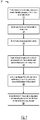
- FIG. 5 is a flow diagram outlining example method steps that can be carried out during the administration of a treatment device 100.
- the method steps can be implemented by any of the example means described herein or by any means that would be known to one of ordinary skill in the art.
- the treatment device having a fan portion, a channel orifice defining an opening in the fan portion, and an agent channel can be provided for administration to a patient.
- the agent channel can be joined to communicate with the channel orifice.
- the treatment device can be delivered to an aneurysm treatment site.
- the fan portion can be expanded to the occluding configuration approximate a center of an aneurysm neck. When the fan portion is expanded to the occluding configuration in step 540, the fan portion can occlude at least a portion of an aneurysm neck.
- Step 540 can also create a barrier between a blood vessel and the aneurysm to prevent the coagulating agent from entering the blood vessel.
- the coagulating agent can be injected through the agent channel and the channel orifice into the aneurysm sac to coagulate the blood present in the aneurysm.
- the treatment device can be collapsed from the occluding configuration to the extraction configuration for extraction of the device after the injection of the coagulating agent.
- Method 500 can further comprise the step of treating an aneurysm with only a single implementation step.
- FIG. 6 is a flow diagram outlining further steps of method 500.
- Method 500 can further comprise step 562 of removing the treatment device through a microcatheter.
- FIG. 7 is a flow diagram outlining further steps of method 500.
- Method 500 can further comprise step 564 of removing the treatment device through a retrieval system.
- FIG. 8 is a flow diagram outlining further steps of method 500.
- Method 500 can further comprise the steps of providing a trigger mechanism (step 542) and triggering the delivery of the agent by activating the trigger mechanism at a proximal end of the agent channel to deliver the agent from the proximal end of the agent channel to a distal end of the agent channel (step 544).
- the present teachings apply equally to the delivery apparatus 100 and treatment device 100 claimed herein.
- the descriptions contained herein are examples of the invention and are not intended in any way to limit the scope of the invention.
- the invention contemplates many variations and modifications of the device for occluding an aneurysm, including alternative geometries of elements and components described herein, utilizing any number of known means for braiding, knitting, weaving, or otherwise forming the fan portion as is known in the art, utilizing any of numerous materials for each component or element (e.g.
- radiopaque materials utilizing additional components including components to deliver a treatment device to an aneurysm or eject an treatment device from a delivery catheter, or utilizing additional components to perform functions not described herein, such as coagulating agents and deployment devices, for example.
- additional components including components to deliver a treatment device to an aneurysm or eject an treatment device from a delivery catheter, or utilizing additional components to perform functions not described herein, such as coagulating agents and deployment devices, for example.
- the methods described herein may be not methods for the treatment of the human or animal body by surgery or therapy.
- the methods may be ex vivo and/or in vitro methods e.g. methods taking place in a laboratory and/or for testing.
Landscapes
- Health & Medical Sciences (AREA)
- Life Sciences & Earth Sciences (AREA)
- Surgery (AREA)
- General Health & Medical Sciences (AREA)
- Engineering & Computer Science (AREA)
- Veterinary Medicine (AREA)
- Biomedical Technology (AREA)
- Heart & Thoracic Surgery (AREA)
- Public Health (AREA)
- Animal Behavior & Ethology (AREA)
- Vascular Medicine (AREA)
- Reproductive Health (AREA)
- Nuclear Medicine, Radiotherapy & Molecular Imaging (AREA)
- Medical Informatics (AREA)
- Molecular Biology (AREA)
- Neurosurgery (AREA)
- Hematology (AREA)
- Anesthesiology (AREA)
- Pulmonology (AREA)
- Biophysics (AREA)
- Surgical Instruments (AREA)
- Media Introduction/Drainage Providing Device (AREA)
Abstract
Description
- The present invention generally relates to medical instruments, and more particularly, to treatment devices for aneurysm therapy.
- Aneurysms can be complicated and difficult to treat. For example, treatment access can be limited or unavailable when an aneurysm is located proximate critical tissues. Such factors are of particular concern with cranial aneurysms due to the brain tissue surrounding cranial vessels and the corresponding limited treatment access.
- Prior solutions have included endovascular treatment access whereby an internal volume of the aneurysm sac is removed or excluded from arterial blood pressure and flow. In this respect, because the interior walls of the aneurysm can continue being subjected to flow of blood and related pressure, aneurysm rupture remains possible.
- Alternatives to endovascular or other surgical approaches can include occlusive devices. Such devices have typically incorporated multiple embolic coils that are delivered to the vasculature using microcatheter delivery systems. For example, when treating cranial aneurysms, a delivery catheter with embolic coils is typically first inserted into non-cranial vasculature through a femoral artery in the hip or groin area. Thereafter, the catheter is guided to a location of interest within the cranium. The sac of the aneurysm can then be filled with the embolic material to create a thrombotic mass that protects the arterial walls from blood flow and related pressure. However, such occlusive devices do have certain shortcomings, including mass effect, which can cause compression on the brain and its nerves. Obtaining an embolic coil packing density sufficient to either occlude the aneurysm neck or fill the aneurysm sac is difficult and time consuming. Further, aneurysm morphology (e.g. wide neck, bifurcation, etc.) can require ancillary devices such as stents or balloons to support the coil mass and obtain the desired packing density. The coils and accompanying ancillary devices can remain in patients for their entire lives. Additionally, embolic coils do not always effectively treat aneurysms as re-canalization of the aneurysm and/or coil compaction can occur over time. Many people who undergo aneurysm coil procedures also require a long period of dual antiplatelet therapy while the patient recovers post-procedure.
- One particular type of occlusive approach endeavors to deliver and treat the entrance or "neck" of the aneurysm as opposed to the volume of the aneurysm by implanting a device in the parent vessel of the aneurysm. In such "neck" approaches, by minimizing blood flow across the neck, a cessation of flow into the aneurysm can be achieved. In turn, a thrombotic mass can naturally form without having to deliver embolic materials into the aneurysm sac, as previously described. However, this approach also has its drawbacks, as the aneurysm does not undergo thromboses immediately, and there is still a risk of rupture post-surgery. Therefore, there is a need for a device capable of simplified and shortened implantation procedures that can quickly inhibit blood flow in an aneurysm to increase patient safety, reduce the length of the patient recovery period, and reduce the length of antiplatelet therapy administration.
- It is an aim of this invention to resolve these and other issues of the art.
- Disclosed herein are various exemplary devices for treating an aneurysm with a coagulating agent. The devices can generally include a fan portion for occluding an aneurysm neck, a channel orifice opening in the fan portion, and an agent channel for delivering a coagulating agent through the orifice into the aneurysm. Devices can be delivered through a catheter to the aneurysm, the fan portion can expand to occlude the aneurysm neck, and the coagulating agent can be injected into the aneurysm. During injection of the coagulating agent, the fan portion can create a barrier to inhibit the coagulating agent from exiting the aneurysm. After injection of the coagulating agent, the fan portion can collapse and the device can be extracted from the patient.
- An example device for occluding an aneurysm can include a fan portion that is expandable from a collapsed configuration to an occluding configuration, a channel orifice, and an agent channel. The fan portion in the occluding configuration can occlude an aneurysm neck to create a barrier between the aneurysm and a blood vessel. This barrier can prevent the coagulating agent from leaking into the blood vessel during and/or after delivery of the agent into the aneurysm sac. The fan portion can extend across and occlude at least a portion of the aneurysm neck or can completely occlude the aneurysm neck in the occluding configuration. The channel orifice can define an opening in the fan portion through which the coagulating agent can be injected. The agent channel can be in communication with the channel orifice and can deliver the coagulating agent through the channel orifice into the aneurysm sac.
- The example device can be delivered to the aneurysm using a microcatheter. The fan portion can detach from its position near the aneurysm neck after the coagulating agent has been delivered to the aneurysm sac. In another example, the fan portion can be collapsed from the occluding configuration to an extraction configuration. This extraction configuration can be sized to fit inside a retrieval catheter.
- The fan portion can consist of at least one elongated support. The elongated support can be connected to an occluding element. In some examples, the elongated support can have a first end and a second end. The first end of the elongated support can be positioned near the channel orifice in the fan portion. The second end of the elongated support can extend towards a wall of the aneurysm across at least a portion of the aneurysm neck to occlude the neck when the fan portion is expanded to the occluding configuration.
- The fan portion can also be inflated to reach the occluding configuration. The device can include an inflation tube to inflate the fan portion to the occluding configuration. The inflation tube can have a distal end connected to the fan portion.
- The agent channel can have a proximal end and a distal end. The distal end of the agent channel can communicate with the channel orifice to transfer the coagulating agent into the aneurysm sac. The proximal end of the agent channel can receive the coagulating agent. The channel orifice can also be an opening in the distal end of the agent channel, whereby a single opening functions as both the channel orifice and the distal end of the agent channel.
- The example device can further have a trigger mechanism in communication with the proximal end of the agent channel. The trigger mechanism can communicate with the proximal end of the agent channel to receive the coagulating agent or introduce the coagulating agent into the agent channel. The trigger mechanism can facilitate delivery of the coagulating agent from the proximal end to the distal end of the agent channel, and then through the channel orifice into the aneurysm sac.
- In another example, a delivery apparatus for treating an aneurysm can have an agent channel that can deliver a coagulating agent to an aneurysm sac. The agent channel can have a distal end and a proximal end. The proximal end of the agent channel can receive the coagulating agent and deliver the coagulating agent from the proximal end to the distal end of the agent channel. The distal end of the agent channel can communicate with a channel orifice in a fan portion and deliver the coagulating agent through the channel orifice into the aneurysm. The channel orifice can also be an opening in the distal end of the agent channel.
- In the example apparatus, the fan portion can expand from a collapsed configuration to an occluding configuration. The fan portion in the occluding configuration can extend across and occlude a portion of an aneurysm neck to create a barrier between a blood vessel and the aneurysm. This barrier can prevent the delivered coagulating agent from entering the blood vessel and help retain the coagulating agent inside the aneurysm sac.
- The fan portion can detach from its position near the aneurysm neck after the coagulating agent has been delivered to the aneurysm sac. The fan portion can collapse from the occluding configuration to an extraction configuration. This extraction configuration can be sized to fit inside a retrieval catheter.
- The example apparatus can further comprise a trigger mechanism in communication with the proximal end of the agent channel for receiving the coagulating agent or introducing the coagulating agent into the agent channel.
- An example method for treating an aneurysm can include providing an exemplary treatment device which can include a fan portion, a channel orifice defining an opening in the fan portion, and an agent channel; joining the agent channel to the channel orifice; delivering the exemplary treatment device to an aneurysm treatment site; expanding the fan portion to an occluding configuration approximate a center of an aneurysm neck wherein the expanded fan portion occludes at least a portion of the aneurysm neck; injecting a coagulating agent through the agent channel, through the channel orifice, and into the aneurysm sac to coagulate the blood present in the aneurysm; and collapsing the treatment device from the occluding configuration to an extraction configuration for extraction of the device after the injection of the coagulating agent.
- The method can include the step of creating a barrier with the fan portion between a blood vessel and the aneurysm to prevent the coagulating agent from entering the blood vessel. The method can include removing the treatment device through a microcatheter or through a retrieval deployment system. The method can include treating an aneurysm with only a single implementation step.
- The method can further include providing a trigger mechanism and triggering the delivery of the agent by activating the trigger mechanism at a proximal end of the agent channel to deliver the agent from the proximal end of the agent channel to a distal end of the agent channel.
- The above and further aspects of this invention are further discussed with reference to the following description in conjunction with the accompanying drawings, in which like numerals indicate like structural elements and features in various figures. The drawings are not necessarily to scale, emphasis instead being placed upon illustrating principles of the invention. The figures depict one or more implementations of the inventive devices, by way of example only, not by way of limitation.
-
FIG. 1 is an illustration of an exemplary treatment device positioned to occlude an aneurysm neck according to aspects of the present invention; -
FIGs. 2a to 2f are illustrations of a treatment sequence of an exemplary treatment device and delivery of a coagulating agent to an aneurysm according to aspects of the present invention; -
FIGs. 3a to 3e are illustrations of a treatment sequence of an exemplary inflatable treatment device and delivery of a coagulating agent to an aneurysm according to aspects of the present invention; -
FIGs. 4a to 4e are illustrations of a treatment sequence of an exemplary treatment device in connection with a trigger mechanism and delivery of a coagulating agent to an aneurysm according to aspects of the present invention; and -
FIG. 5 is a flow diagram outlining example method steps that can be carried out during delivery and use of a treatment device according to aspects of the present invention. -
FIG. 6 is a flow diagram outlining example method steps that can be carried out during delivery and use of a treatment device according to aspects of the present invention. -
FIG. 7 is a flow diagram outlining example method steps that can be carried out during delivery and use of a treatment device according to aspects of the present invention. -
FIG. 8 is a flow diagram outlining example method steps that can be carried out during delivery and use of a treatment device according to aspects of the present invention. - The descriptions contained herein are examples of the invention and are not intended in any way to limit the scope of the invention. In general, example devices described herein describe a treatment device that can be placed over the neck of an aneurysm to create a barrier between a vessel and the aneurysm. At least one coagulating agent can then delivered into the aneurysm sac. Delivery can be activated via trigger mechanism on the proximal end of the delivery system. The device can be held approximate the aneurysm neck at least until the coagulating agent is injected, and then can be retracted or detached from the aneurysm. The rapid coagulating agents can coagulate the blood in the aneurysm instantly. In some examples, the device can be removed via a microcatheter or deployed via a retrieval deployment system.
- The example devices can include a fan portion that can expand from a collapsed configuration to an occluding configuration in which the fan portion in the occluding configuration is shaped to occlude an aneurysm neck from within an aneurysm sac. In the occluding configuration, the fan portion can generally have a channel orifice working in connection with an agent channel that delivers a coagulating agent through the channel orifice and into the aneurysm sac.
- It must be noted that, as used in the specification and the appended claims, the singular forms "a," "an" and "the" include plural referents unless the context clearly dictates otherwise. By "comprising" or "containing" or "including" it is meant that at least the named compound, element, particle, or method step is present in the composition or article or method, but does not exclude the presence of other compounds, materials, particles, method steps, even if the other such compounds, material, particles, method steps have the same function as what is named.
- In describing examples, terminology will be resorted to for the sake of clarity. It is intended that each term contemplates its broadest meaning as understood by those skilled in the art and includes all technical equivalents that operate in a similar manner to accomplish a similar purpose. It is also to be understood that the mention of one or more steps of a method does not preclude the presence of additional method steps or intervening method steps between those steps expressly identified. Steps of a method can be performed in a different order than those described herein without departing from the scope of the disclosed technology. Similarly, it is also to be understood that the mention of one or more components in a device or system does not preclude the presence of additional components or intervening components between those components expressly identified.
- Turning to
FIG. 1 , anexample treatment device 100 is shown with thefan portion 102 in an occluding configuration approximate theneck 12 of ananeurysm 10. Thefan portion 102 can occlude theaneurysm 10 from inside theaneurysm sac 16. Thefan portion 102 in the occluding configuration can be sized to occlude at least a portion of theaneurysm neck 12. Thefan portion 102 in the occluding configuration can completely occlude theaneurysm neck 12 as depicted inFIG. 1 . Thefan portion 102 in the occluding configuration can occlude theneck 12 to create a barrier between ablood vessel 106 and theaneurysm 10. Thefan portion 102 can contain achannel orifice 104. As illustrated, thechannel orifice 104 can be located in thefan portion 102 such that thechannel orifice 104 opens up to theaneurysm 10. Thechannel orifice 104 can be centrally located in thefan portion 102. The channel orifice can work in connection with anagent channel 112. -
FIGs. 2a through 2f are illustrations of stages or steps that can occur during a treatment sequence of anexemplary treatment device 100 and delivery of a coagulatingagent 114 to ananeurysm 10. The coagulatingagent 114 can be a drug based on replacement factors, vitamin K, antiplasmins or any other drugs known to those of skill in the art that can affect blood clotting. In some examples, a rapidly clotting drug can be effective. In addition, the drug needs to be deliverable through atorturous agent channel 112. -
FIG. 2a is an illustration of anexample treatment device 100 wherein thefan portion 102 is shown in a collapsed delivery configuration inside adelivery catheter 400, achannel orifice 104 positioned on a proximal end of thecollapsed fan portion 102, and anagent channel 112 attached to thechannel orifice 104. Thefan portion 102 can be sized to fit within the lumen of adelivery catheter 400 when thefan portion 102 is in the collapsed configuration. Thetreatment device 100 in its entirety can be sized to fit within the lumen of adelivery catheter 400 when thefan portion 102 is in the collapsed configuration. When thefan portion 102 is in the collapsed configuration, thefan portion 102 can have sufficient flexibility to be delivered through thedelivery catheter 400, navigating torturous anatomical geometries, to be delivered to an aneurysm 10 (not shown). Theagent channel 112 can have sufficient length to be accessible outside of the patient when thefan portion 102 reaches a treatment site. Thefan portion 102 in the collapsed configuration can have a substantially tubular shape. Thefan portion 102 can be comprised of at least oneelongated support 108. The example inFIG. 2a shows threeelongated supports 108 comprising thefan portion 102. An occludingelement 110 can be attached to the one or moreelongated supports 108. - Moving on to
FIG. 2b , thetreatment device 100 can be delivered to ananeurysm 10 by sliding thedevice 100 distally when thefan portion 102 is in a collapsed configuration through adelivery catheter 400. Thetreatment device 100 can be delivered to a treatment site through ablood vessel 106.FIG. 2b illustrates thetreatment device 100 inside thedelivery catheter 400 located near ananeurysm neck 12.FIG. 2b further shows thefan portion 102 pushed partially out of thedelivery catheter 400 for deployment inside theaneurysm sac 16. Thefan portion 102 can expand as it exits thedelivery catheter 400. Thefan portion 102 can include a memory shape material such as Nitinol, a Nitinol alloy, a polymer memory shape material, or other memory shape material having properties for reshaping as described herein. Thefan portion 102 can be in a deformed shape in the collapsed configuration and reshape based on a predetermined shape after exiting thedelivery catheter 400. As illustrated inFIG. 2b , eachelongated support 108 of thefan portion 102 can have afirst end 108a positioned approximate thechannel orifice 104, and asecond end 108b extending from thefirst end 108a across at least a portion of theaneurysm neck 12 towards ananeurysm wall 14. Thesecond end 108b can extend towards theinterior wall 14 of theaneurysm 10 upon expansion of thefan portion 102. When eachelongated support 108 expands, theelongated support 108 can in turn expand the connected occludingelement 110 to occlude at least a portion of theaneurysm neck 12. In another example, the occludingelement 110 can expand upon discharge from thedelivery catheter 400 and cause thesecond end 108b of each connectedelongated support 108 to move towards theaneurysm wall 14. -
FIG. 2c illustrates theexample treatment device 100 wherein thefan portion 102 is in an occluding configuration in theaneurysm 10. Thefan portion 102 in the occluding configuration can be sized to occlude at least a portion of ananeurysm neck 12. Thefan portion 102 in the occluding configuration can completely occlude theaneurysm neck 12 as depicted inFIG. 2c . Thefan portion 102 in the occluding configuration can occlude theneck 12 to create a barrier between ablood vessel 106 and theaneurysm 10. As illustrated inFIG. 2c , thesecond end 108b of theelongated support 108 can be in contact with theaneurysm wall 14 when thefan portion 102 is in the occluding configuration. In occluding configuration, thefan portion 102 can be capable of deflecting a blood flow from theaneurysm 10, diverting a blood flow from theaneurysm 10, slowing a blood flow into theaneurysm 10, or any combination thereof. - In the occluding configuration, the
fan portion 102 can extend to theaneurysm wall 14, and thefan portion 102 can provide a force against theaneurysm wall 14 to maintain the expanded position of thefan portion 102 such that thetreatment device 100 doesn't become dislodged and become ineffective at inhibiting blood flow into the aneurysm. The force of thefan portion 102 to theaneurysm wall 14 can be sufficient to maintain the position of thetreatment device 100 within theaneurysm 10. For example, thefan portion 102 can be made of a memory shape material having a first, predetermined shape and a second, collapsed shape in the collapsed configuration. When thefan portion 102 is in an occluding configuration within theaneurysm 10, thefan portion 102 can move to a third, deployed shape that is based at least in part on the first, predetermined shape and the anatomical geometry of theaneurysm 10. In the example, the first, predetermined shape can be sized larger than thewall 14 within theaneurysm sac 16; thefan portion 102 can move to extend to thewall 14; and thefan portion 102 can provide a force against thewall 14 as the properties of the memory shape material cause thefan portion 102 to attempt to open to the predetermined shape. Thefan portion 102 in the occluding configuration can take the shape of theaneurysm neck 12 and/orinterior walls 14 of the aneurysm near theaneurysm neck 12. -
FIG. 2d is an illustration of a cross-sectional view looking distally into theaneurysm 10 of anexample treatment device 100 where thefan portion 102 is in the occluding configuration, such as thetreatment device 100 depicted inFIG. 2c . -
FIG. 2e illustrates thetreatment device 100 wherein thefan portion 102 is in the occluding configuration. Thechannel orifice 104 in thefan portion 102 can work in connection with anagent channel 112. Theagent channel 112 can allow for the transfer of one ormore coagulating agents 114 through thechannel 112 to thechannel orifice 104. The coagulatingagent 114 can include rapid coagulating agents, such as collagen, chitosan, kaolin, zeolite, or other agents having properties for coagulating as described herein. Theagent channel 112 can have adistal end 112a a proximal end (not shown). Thedistal end 112a of theagent channel 112 can connect to thechannel orifice 104. The proximal end can receive the coagulatingagent 114 into theagent channel 112 and deliver the coagulatingagent 114 from the proximal end to thedistal end 112a connected to thechannel orifice 104. The proximal end can be accessible outside of the patient for injection of the coagulatingagent 114 into the patient.Coagulating agent 114 passing through the lumen of theagent channel 112 to thedistal end 112a can subsequently pass through thechannel orifice 104 and into theaneurysm sac 16 upon reaching thedistal end 112a of theagent channel 112. Thedistal end 112a of theagent channel 112 can also be thechannel orifice 104 of thefan portion 102. The coagulatingagent 114 can coagulate the blood inside theaneurysm 10. The coagulatingagent 114 can coagulate the blood inside theaneurysm 10 virtually instantaneously upon contacting the blood inside theaneurysm 10 according to the coagulation properties of the coagulatingagent 114. - As shown in
FIG. 2f , once the coagulatingagent 114 has been pumped into theaneurysm sac 16, thetreatment device 100 can be removed from theaneurysm 10. Thetreatment device 100 can be removed once the coagulatingagent 114 has coagulated the blood in theaneurysm 10. Thetreatment device 100 can detach from its location approximate theaneurysm neck 12 after delivery of the coagulatingagent 114. As in the device shown inFIG. 2e , the occludingelement 110, theelongated supports 108, or both the occludingelement 110 and theelongated supports 108 can detach from their location approximate theaneurysm neck 12 after delivery of the coagulatingagent 114. In another example, thetreatment device 100 can be removed via a retrieval deployment system. In another example, the fan portion 102 (not shown) can collapse from the occluding configuration to an extraction configuration after the coagulatingagent 114 has been delivered to theaneurysm sac 16. The extraction configuration can be sized to traverse through a lumen of a catheter (not shown). Theaneurysm 10, now filled with the coagulatingagent 114 can now start to be reabsorbed into theblood vessel 106 through the body's natural healing process. This can avoid the need for permanently implanted elements in the patient. -
FIGs. 3a to 3e are illustrations of stages or steps that can occur during another example implementation sequence of anexemplary treatment device 100.FIG. 3a illustrates anexample treatment device 100 comprising afan portion 102 having achannel orifice 104, anagent channel 112 connected to thechannel orifice 104 at adistal end 112a of theagent channel 112, and aninflation tube 118 connected to thefan portion 102. Thefan portion 102 is shown in a collapsed delivery configuration inside adelivery catheter 400. Thefan portion 102 can be in connection with theinflation tube 118 which can inflate thefan portion 102. Thefan portion 102 can include at least one material used in neurovascular balloons, such as polyurethane or silicon. Theinflation tube 118 can have adistal end 118a connected to thefan portion 102. -
FIG. 3b illustrates thetreatment device 100 inside thedelivery catheter 400 with thefan portion 102 exiting thedelivery catheter 104 for deployment inside asac 16 of ananeurysm 10. As shown inFIG. 3b , thefan portion 102 can be inflated to expand using theinflation tube 118 as it exits thedelivery catheter 400. Thefan portion 102 can be completely removed from thedelivery catheter 400 before inflation begins. Alternatively, inflation of thefan portion 102 can begin while thefan portion 102 is still entirely or partially inside thedelivery catheter 400. Inflation of thefan portion 102 can occur using saline or a variety of other elements known in the art with respect to inflating neurovascular balloons. As thefan portion 102 inflates, the outer surface of thefan portion 102 can expand towards theaneurysm wall 14. -
FIG. 3c illustrates thetreatment device 100 wherein thefan portion 102 is in an occluding configuration in theaneurysm 10. As illustrated inFIG. 3c ,fan portion 102 can inflate to the extent that thefan portion 102 can be in contact with theaneurysm wall 14 when thefan portion 102 is in the occluding configuration.FIG. 3c illustrates the delivery of a coagulatingagent 114 to theaneurysm sac 16 in the same manner as described inFIG. 2e . -
FIG. 3d illustratescoagulation agent 114 delivered into theaneurysm sac 16 and aretrieval catheter 500 in place to extract thedevice 100. Thefan portion 102 can collapse from the occluding configuration to an extraction configuration after the coagulatingagent 114 has been delivered to theaneurysm sac 16. The extraction configuration can be sized to traverse through a lumen of theretrieval catheter 500. Thetreatment device 100 can be extracted using theretrieval catheter 500 or a deployment and retrieval device. Thedelivery catheter 400 can also be theretrieval catheter 500.FIG. 3e illustrates the aneurysm following extraction of theretrieval catheter 500 and thetreatment device 100. Once the coagulatingagent 114 has been pumped into theaneurysm sac 16, thefan portion 102 can detach from its location approximate theaneurysm neck 12. Thefan portion 102 can deflate from the occluding configuration to an extraction configuration after the coagulatingagent 114 has been delivered to theaneurysm sac 16. -
FIGs. 4a to 4e are illustrations of stages or steps that can occur during another example implementation sequence of anexemplary treatment device 100.FIG. 4a is an illustration of anexample treatment device 100 including afan portion 102, achannel orifice 104, anagent channel 112, and atrigger mechanism 116. Thefan portion 102 is shown in a collapsed delivery configuration inside adelivery catheter 400. Thefan portion 102 can contain thechannel orifice 104 that can be in communication with anagent channel 112. Theagent channel 112 can have aproximal end 112b in communication with thetrigger mechanism 116. Theproximal end 112b of theagent channel 112 can receive the coagulatingagent 114 into theagent channel 112 for delivery. Thetrigger mechanism 116 can facilitate the delivery of the coagulating agent to an aneurysm sac 16 (not shown). -
FIG. 4b illustrates thetreatment device 100 inside thedelivery catheter 400 with thefan portion 102 exiting thedelivery catheter 400 for deployment inside theaneurysm sac 16. As illustrated inFIGs. 4b to 4d , the treatment site can include ananeurysm 10 positioned adjacent bifurcated blood vessel branches and thetreatment device 100 can be delivered to theaneurysm 10 through astem branch 106 feeding the bifurcated blood vessel branches. -
FIG. 4c illustrates thetreatment device 100 wherein thefan portion 102 is in an occluding configuration in theaneurysm 10. Upon the fan portion reaching the occluding configuration, thetrigger mechanism 116 can facilitate the delivery of the coagulatingagent 114 through theagent channel 112 to theaneurysm sac 16. Thetrigger mechanism 116 can be operated to release the coagulatingagent 114 by a physician, nurse, or other medical professional.FIG. 4d illustrates the delivery of a coagulatingagent 114 to theaneurysm sac 16 in the same manner as described inFIG. 2e .FIG. 4e illustrates the aneurysm following extraction of theretrieval catheter 500 and thetreatment device 100. -
FIG. 5 is a flow diagram outlining example method steps that can be carried out during the administration of atreatment device 100. The method steps can be implemented by any of the example means described herein or by any means that would be known to one of ordinary skill in the art. - Referring to a
method 500 outlined inFIG. 5 , instep 510 the treatment device having a fan portion, a channel orifice defining an opening in the fan portion, and an agent channel can be provided for administration to a patient. Instep 520, the agent channel can be joined to communicate with the channel orifice. Instep 530, the treatment device can be delivered to an aneurysm treatment site. Instep 540, the fan portion can be expanded to the occluding configuration approximate a center of an aneurysm neck. When the fan portion is expanded to the occluding configuration instep 540, the fan portion can occlude at least a portion of an aneurysm neck. Step 540 can also create a barrier between a blood vessel and the aneurysm to prevent the coagulating agent from entering the blood vessel. Instep 550, the coagulating agent can be injected through the agent channel and the channel orifice into the aneurysm sac to coagulate the blood present in the aneurysm. Instep 560, the treatment device can be collapsed from the occluding configuration to the extraction configuration for extraction of the device after the injection of the coagulating agent.Method 500 can further comprise the step of treating an aneurysm with only a single implementation step. -
FIG. 6 is a flow diagram outlining further steps ofmethod 500.Method 500 can further comprisestep 562 of removing the treatment device through a microcatheter.FIG. 7 is a flow diagram outlining further steps ofmethod 500.Method 500 can further comprisestep 564 of removing the treatment device through a retrieval system.FIG. 8 is a flow diagram outlining further steps ofmethod 500.Method 500 can further comprise the steps of providing a trigger mechanism (step 542) and triggering the delivery of the agent by activating the trigger mechanism at a proximal end of the agent channel to deliver the agent from the proximal end of the agent channel to a distal end of the agent channel (step 544). - It should be apparent to those skilled in the art that the present teachings apply equally to the
delivery apparatus 100 andtreatment device 100 claimed herein. The descriptions contained herein are examples of the invention and are not intended in any way to limit the scope of the invention. As described herein, the invention contemplates many variations and modifications of the device for occluding an aneurysm, including alternative geometries of elements and components described herein, utilizing any number of known means for braiding, knitting, weaving, or otherwise forming the fan portion as is known in the art, utilizing any of numerous materials for each component or element (e.g. radiopaque materials, memory shape materials, etc.), utilizing additional components including components to deliver a treatment device to an aneurysm or eject an treatment device from a delivery catheter, or utilizing additional components to perform functions not described herein, such as coagulating agents and deployment devices, for example. These modifications would be apparent to those having ordinary skill in the art to which this invention relates and are intended to be within the scope of the claims which follow. - The methods described herein may be not methods for the treatment of the human or animal body by surgery or therapy. For example, the methods may be ex vivo and/or in vitro methods e.g. methods taking place in a laboratory and/or for testing.
-
- 1. A method for treating an aneurysm comprising:
- providing a treatment device comprising a fan portion, a channel orifice defining an opening in the fan portion, and an agent channel;
- joining the agent channel to communicate with the channel orifice;
- delivering the treatment device to an aneurysm treatment site;
- expanding the fan portion to an occluding configuration approximate a center of an aneurysm neck, wherein the expanded fan portion occludes at least a portion of the aneurysm neck;
- injecting a coagulating agent through the agent channel and the channel orifice into the aneurysm sac to coagulate the blood present in the aneurysm; and
- collapsing the treatment device from the occluding configuration to an extraction configuration for extraction of the device after the injection of the coagulating agent.
- 2. The method of embodiment 1 wherein the step of expanding the fan portion to an occluding configuration approximate a center of an aneurysm neck further comprises the step of creating a barrier between a blood vessel and the aneurysm to prevent the coagulating agent from entering the blood vessel.
- 3. The method of embodiment 1 or embodiment 2 further comprising the step of removing the treatment device through a retrieval catheter.
- 4. The method of any one of embodiments 1 to 3 further comprising the step of removing the treatment device through a retrieval deployment system.
- 5. The method of any one of embodiments 1 to 4 further comprising the step of treating an aneurysm with only a single implementation step.
- 6. The method of any one of embodiments 1 to 5 further comprising the steps of:
- providing a trigger mechanism; and
- triggering the delivery of the agent by activating the trigger mechanism at a proximal end of the agent channel to deliver the agent from the proximal end of the agent channel to a distal end of the agent channel.
Claims (15)
- A treatment device for treating an aneurysm comprising:a fan portion expandable from a collapsed configuration to an occluding configuration, the occluding configuration sized to extend across and occlude at least a portion of a neck of the aneurysm;a channel orifice defining an opening in the fan portion, wherein in the occluding configuration the channel orifice is open to the aneurysm; andan agent channel in communication with the channel orifice for delivering a coagulating agent to the aneurysm sac through the channel orifice.
- The treatment device of claim 1 wherein the occluding configuration occludes the neck to create a barrier between a blood vessel and the aneurysm to prevent the coagulating agent from entering the blood vessel.
- The treatment device of claim 1 or claim 2wherein the fan portion is further collapsible from the occluding configuration to an extraction configuration following delivery of the coagulating agent to the aneurysm sac, the extraction configuration sized to traverse through a lumen of a retrieval catheter.
- The treatment device of any one of the preceding claims wherein the fan portion comprises at least one elongated support and an occluding element affixed to each elongated support, each elongated support comprising:a first end positioned approximate the channel orifice; anda second end extending from the first end across at least a portion of the aneurysm neck towards an aneurysm wall.
- The treatment device of any one of the preceding claims wherein the fan portion is detachable from the aneurysm neck after the coagulating agent is injected into the aneurysm sac.
- The treatment device of any one of the preceding claims wherein the fan portion in the occluding configuration completely occludes the aneurysm neck.
- The treatment device of any one of the preceding claims wherein the fan portion is inflatable.
- The treatment device of claim 7 further comprising an inflation tube for inflating the fan portion, the inflation tube comprising a distal end connected to the fan portion.
- The treatment device of any one of the preceding claims further comprising:a trigger mechanism for introducing the coagulating agent into the agent channel;wherein the agent channel comprises a proximal end in communication with the trigger mechanism to receive the coagulating agent into the agent channel and a distal end in communication with the channel orifice; andwherein the agent channel delivers the coagulating agent from the proximal end to the distal end and through the channel orifice into the sac of the aneurysm.
- The treatment device of claim 9 wherein the channel orifice is an opening in the distal end of the agent channel.
- A delivery apparatus for treating an aneurysm comprising:an agent channel delivering a coagulating agent to an aneurysm sac;wherein the agent channel comprises a distal end and a proximal end to receive the coagulating agent into the agent channel and delivers the coagulating agent from the proximal end to the distal end;a channel orifice defining an opening in a fan portion, wherein the distal end of the agent channel communicates with channel orifice to deliver the coagulating agent through the fan portion; andwherein the fan portion is expandable from a collapsed configuration to an occluding configuration, the occluding configuration sized to extend across and occlude at least a portion of a neck of the aneurysm to create a barrier between a blood vessel and the aneurysm preventing the delivered coagulating agent from entering the blood vessel and facilitating the retention of the coagulating agent in the aneurysm sac.
- The delivery apparatus of claim 11 wherein the fan portion is further collapsible from the occluding configuration to an extraction configuration following delivery of the coagulating agent to the aneurysm sac, the extraction configuration sized to traverse through a lumen of a retrieval catheter.
- The delivery apparatus of claim 11 or claim 12 further comprising a trigger mechanism in communication with the proximal end of the agent channel for introducing the coagulating agent into the agent channel.
- The delivery apparatus of any one of claims 11 to 13 wherein the channel orifice is an opening in the distal end of the agent channel.
- A method for treating an aneurysm comprising:providing a treatment device comprising a fan portion, a channel orifice defining an opening in the fan portion, and an agent channel;joining the agent channel to communicate with the channel orifice;delivering the treatment device to an aneurysm treatment site;expanding the fan portion to an occluding configuration approximate a center of an aneurysm neck, wherein the expanded fan portion occludes at least a portion of the aneurysm neck;injecting a coagulating agent through the agent channel and the channel orifice into the aneurysm sac to coagulate the blood present in the aneurysm; andcollapsing the treatment device from the occluding configuration to an extraction configuration for extraction of the device after the injection of the coagulating agent.
Applications Claiming Priority (1)
| Application Number | Priority Date | Filing Date | Title |
|---|---|---|---|
| US16/218,129 US11406392B2 (en) | 2018-12-12 | 2018-12-12 | Aneurysm occluding device for use with coagulating agents |
Publications (1)
| Publication Number | Publication Date |
|---|---|
| EP3666201A1 true EP3666201A1 (en) | 2020-06-17 |
Family
ID=68886859
Family Applications (1)
| Application Number | Title | Priority Date | Filing Date |
|---|---|---|---|
| EP19215277.5A Withdrawn EP3666201A1 (en) | 2018-12-12 | 2019-12-11 | Aneurysm occluding device for use with coagulating agents |
Country Status (5)
| Country | Link |
|---|---|
| US (2) | US11406392B2 (en) |
| EP (1) | EP3666201A1 (en) |
| JP (1) | JP2020093100A (en) |
| KR (1) | KR20200072434A (en) |
| CN (1) | CN111297429B (en) |
Families Citing this family (1)
| Publication number | Priority date | Publication date | Assignee | Title |
|---|---|---|---|---|
| CN112656477B (en) * | 2020-12-31 | 2023-06-20 | 杭州德诺脑神经医疗科技有限公司 | Aneurysm occlusion device and its microcatheter |
Citations (4)
| Publication number | Priority date | Publication date | Assignee | Title |
|---|---|---|---|---|
| US6454780B1 (en) * | 2001-06-21 | 2002-09-24 | Scimed Life Systems, Inc. | Aneurysm neck obstruction device |
| US20040153120A1 (en) * | 2003-02-03 | 2004-08-05 | Seifert Paul S. | Systems and methods of de-endothelialization |
| WO2007076480A2 (en) * | 2005-12-23 | 2007-07-05 | Levy Elad I | Bifurcated aneurysm treatment arrangement |
| DE102013106031A1 (en) * | 2013-06-11 | 2014-12-11 | Acandis Gmbh & Co. Kg | Medical implant and system with such an implant |
Family Cites Families (400)
| Publication number | Priority date | Publication date | Assignee | Title |
|---|---|---|---|---|
| US2849002A (en) | 1956-03-12 | 1958-08-26 | Vincent J Oddo | Haemostatic catheter |
| US3480017A (en) | 1966-04-27 | 1969-11-25 | Wallace B Shute | Cervical dilator |
| US4085757A (en) | 1976-04-29 | 1978-04-25 | P Pevsner | Miniature balloon catheter method and apparatus |
| US4282875A (en) | 1979-01-24 | 1981-08-11 | Serbinenko Fedor A | Occlusive device |
| US4395806A (en) | 1980-05-08 | 1983-08-02 | Sorenson Research Co., Inc. | Method of manufacturing a detachable balloon catheter assembly |
| US4364392A (en) | 1980-12-04 | 1982-12-21 | Wisconsin Alumni Research Foundation | Detachable balloon catheter |
| US4545367A (en) | 1982-07-16 | 1985-10-08 | Cordis Corporation | Detachable balloon catheter and method of use |
| US4517979A (en) | 1983-07-14 | 1985-05-21 | Cordis Corporation | Detachable balloon catheter |
| EP0375775B1 (en) | 1986-11-29 | 1994-08-31 | Terumo Kabushiki Kaisha | Catheter equipped with balloon |
| US4836204A (en) | 1987-07-06 | 1989-06-06 | Landymore Roderick W | Method for effecting closure of a perforation in the septum of the heart |
| US5067489A (en) | 1988-08-16 | 1991-11-26 | Flexmedics Corporation | Flexible guide with safety tip |
| FR2641692A1 (en) | 1989-01-17 | 1990-07-20 | Nippon Zeon Co | Plug for closing an opening for a medical application, and device for the closure plug making use thereof |
| US4991602A (en) | 1989-06-27 | 1991-02-12 | Flexmedics Corporation | Flexible guide wire with safety tip |
| US5065772A (en) | 1989-10-13 | 1991-11-19 | Inamed Corporation | Inflatable cerivical pessary |
| US6425893B1 (en) | 1990-03-13 | 2002-07-30 | The Regents Of The University Of California | Method and apparatus for fast electrolytic detachment of an implant |
| US5122136A (en) | 1990-03-13 | 1992-06-16 | The Regents Of The University Of California | Endovascular electrolytically detachable guidewire tip for the electroformation of thrombus in arteries, veins, aneurysms, vascular malformations and arteriovenous fistulas |
| JPH0546421Y2 (en) | 1990-08-23 | 1993-12-06 | ||
| US5025060A (en) | 1990-10-15 | 1991-06-18 | Kansai Paint Co., Ltd. | Dispersion of fine particles of a polymer |
| CA2380683C (en) | 1991-10-28 | 2006-08-08 | Advanced Cardiovascular Systems, Inc. | Expandable stents and method for making same |
| US5261916A (en) | 1991-12-12 | 1993-11-16 | Target Therapeutics | Detachable pusher-vasoocclusive coil assembly with interlocking ball and keyway coupling |
| DK0791333T3 (en) | 1991-12-12 | 2000-05-01 | Target Therapeutics Inc | Several extruder-carocclusion coil construction with interlocking coupling |
| US5342387A (en) | 1992-06-18 | 1994-08-30 | American Biomed, Inc. | Artificial support for a blood vessel |
| US5350397A (en) | 1992-11-13 | 1994-09-27 | Target Therapeutics, Inc. | Axially detachable embolic coil assembly |
| US5334210A (en) | 1993-04-09 | 1994-08-02 | Cook Incorporated | Vascular occlusion assembly |
| US5624449A (en) | 1993-11-03 | 1997-04-29 | Target Therapeutics | Electrolytically severable joint for endovascular embolic devices |
| US5423829A (en) | 1993-11-03 | 1995-06-13 | Target Therapeutics, Inc. | Electrolytically severable joint for endovascular embolic devices |
| JP2605559Y2 (en) | 1993-12-21 | 2000-07-24 | 株式会社パイオラックス | Treatment device for tubular organs |
| EP1221307B1 (en) | 1994-07-08 | 2010-02-17 | ev3 Inc. | System for performing an intravascular procedure |
| US5846261A (en) | 1994-07-08 | 1998-12-08 | Aga Medical Corp. | Percutaneous catheter directed occlusion devices |
| US5814062A (en) | 1994-12-22 | 1998-09-29 | Target Therapeutics, Inc. | Implant delivery assembly with expandable coupling/decoupling mechanism |
| IL116561A0 (en) | 1994-12-30 | 1996-03-31 | Target Therapeutics Inc | Severable joint for detachable devices placed within the body |
| US5634936A (en) | 1995-02-06 | 1997-06-03 | Scimed Life Systems, Inc. | Device for closing a septal defect |
| US5645558A (en) | 1995-04-20 | 1997-07-08 | Medical University Of South Carolina | Anatomically shaped vasoocclusive device and method of making the same |
| RU2157146C2 (en) | 1995-06-13 | 2000-10-10 | ВИЛЬЯМ КУК Европа, A/S | Device for performing implantation in blood vessels and hollow organs |
| US6168622B1 (en) | 1996-01-24 | 2001-01-02 | Microvena Corporation | Method and apparatus for occluding aneurysms |
| US5733294A (en) | 1996-02-28 | 1998-03-31 | B. Braun Medical, Inc. | Self expanding cardiovascular occlusion device, method of using and method of making the same |
| US5853422A (en) | 1996-03-22 | 1998-12-29 | Scimed Life Systems, Inc. | Apparatus and method for closing a septal defect |
| US6949116B2 (en) | 1996-05-08 | 2005-09-27 | Carag Ag | Device for plugging an opening such as in a wall of a hollow or tubular organ including biodegradable elements |
| US5964797A (en) | 1996-08-30 | 1999-10-12 | Target Therapeutics, Inc. | Electrolytically deployable braided vaso-occlusion device |
| US5941249A (en) | 1996-09-05 | 1999-08-24 | Maynard; Ronald S. | Distributed activator for a two-dimensional shape memory alloy |
| US6007573A (en) | 1996-09-18 | 1999-12-28 | Microtherapeutics, Inc. | Intracranial stent and method of use |
| US6254628B1 (en) | 1996-12-09 | 2001-07-03 | Micro Therapeutics, Inc. | Intracranial stent |
| US5951599A (en) | 1997-07-09 | 1999-09-14 | Scimed Life Systems, Inc. | Occlusion system for endovascular treatment of an aneurysm |
| US5928260A (en) | 1997-07-10 | 1999-07-27 | Scimed Life Systems, Inc. | Removable occlusion system for aneurysm neck |
| US7569066B2 (en) * | 1997-07-10 | 2009-08-04 | Boston Scientific Scimed, Inc. | Methods and devices for the treatment of aneurysms |
| JP4060528B2 (en) | 1997-08-04 | 2008-03-12 | ボストン サイエンティフィック コーポレーション | Occlusion system for aneurysm treatment |
| WO1999008607A1 (en) | 1997-08-05 | 1999-02-25 | Boston Scientific Limited | Detachable aneurysm neck bridge |
| US6063070A (en) | 1997-08-05 | 2000-05-16 | Target Therapeutics, Inc. | Detachable aneurysm neck bridge (II) |
| GB9716497D0 (en) | 1997-08-05 | 1997-10-08 | Bridport Gundry Plc | Occlusion device |
| US6086577A (en) | 1997-08-13 | 2000-07-11 | Scimed Life Systems, Inc. | Detachable aneurysm neck bridge (III) |
| US5916235A (en) | 1997-08-13 | 1999-06-29 | The Regents Of The University Of California | Apparatus and method for the use of detachable coils in vascular aneurysms and body cavities |
| US6146373A (en) * | 1997-10-17 | 2000-11-14 | Micro Therapeutics, Inc. | Catheter system and method for injection of a liquid embolic composition and a solidification agent |
| US6036720A (en) | 1997-12-15 | 2000-03-14 | Target Therapeutics, Inc. | Sheet metal aneurysm neck bridge |
| JP2003522550A (en) | 1998-02-10 | 2003-07-29 | アーテミス・メディカル・インコーポレイテッド | Occlusion, fixation, tensioning, and diverting devices and methods of use |
| US6379374B1 (en) | 1998-10-22 | 2002-04-30 | Cordis Neurovascular, Inc. | Small diameter embolic coil hydraulic deployment system |
| US6063100A (en) | 1998-03-10 | 2000-05-16 | Cordis Corporation | Embolic coil deployment system with improved embolic coil |
| US5925060A (en) | 1998-03-13 | 1999-07-20 | B. Braun Celsa | Covered self-expanding vascular occlusion device |
| CA2326504A1 (en) | 1998-03-30 | 1999-10-07 | David Forest Kallmes | Flow arrest, double balloon technique for occluding aneurysms or blood vessels |
| US6168615B1 (en) | 1998-05-04 | 2001-01-02 | Micrus Corporation | Method and apparatus for occlusion and reinforcement of aneurysms |
| SE514546C2 (en) | 1998-05-18 | 2001-03-12 | Allgon Ab | An antenna system and a radio communication device comprising an antenna system |
| US6463317B1 (en) | 1998-05-19 | 2002-10-08 | Regents Of The University Of Minnesota | Device and method for the endovascular treatment of aneurysms |
| US6113609A (en) | 1998-05-26 | 2000-09-05 | Scimed Life Systems, Inc. | Implantable tissue fastener and system for treating gastroesophageal reflux disease |
| US5935148A (en) | 1998-06-24 | 1999-08-10 | Target Therapeutics, Inc. | Detachable, varying flexibility, aneurysm neck bridge |
| US6096175A (en) | 1998-07-17 | 2000-08-01 | Micro Therapeutics, Inc. | Thin film stent |
| EP1109499B1 (en) | 1998-09-04 | 2007-08-15 | Boston Scientific Limited | Detachable aneurysm neck closure patch |
| US7410482B2 (en) | 1998-09-04 | 2008-08-12 | Boston Scientific-Scimed, Inc. | Detachable aneurysm neck bridge |
| AU6288799A (en) | 1998-10-09 | 2000-05-01 | Cook Incorporated | Vasoocclusion coil device having a core therein |
| US7044134B2 (en) | 1999-11-08 | 2006-05-16 | Ev3 Sunnyvale, Inc | Method of implanting a device in the left atrial appendage |
| US7128073B1 (en) | 1998-11-06 | 2006-10-31 | Ev3 Endovascular, Inc. | Method and device for left atrial appendage occlusion |
| US6569179B2 (en) | 1998-11-10 | 2003-05-27 | Scimed Life Systems, Inc. | Bioactive three loop coil |
| US8016852B2 (en) | 1998-11-10 | 2011-09-13 | Stryker Corporation | Bioactive components for incorporation with vaso-occlusive members |
| US6080183A (en) | 1998-11-24 | 2000-06-27 | Embol-X, Inc. | Sutureless vessel plug and methods of use |
| EP1582178B1 (en) | 1999-02-01 | 2012-09-26 | Board Of Regents, The University Of Texas System | Woven intravascular devices and methods for making the same and apparatus for delivery of the same |
| US6428558B1 (en) | 1999-03-10 | 2002-08-06 | Cordis Corporation | Aneurysm embolization device |
| US6375606B1 (en) | 1999-03-17 | 2002-04-23 | Stereotaxis, Inc. | Methods of and apparatus for treating vascular defects |
| US6858034B1 (en) | 1999-05-20 | 2005-02-22 | Scimed Life Systems, Inc. | Stent delivery system for prevention of kinking, and method of loading and using same |
| US6375668B1 (en) | 1999-06-02 | 2002-04-23 | Hanson S. Gifford | Devices and methods for treating vascular malformations |
| US6379329B1 (en) | 1999-06-02 | 2002-04-30 | Cordis Neurovascular, Inc. | Detachable balloon embolization device and method |
| US6551303B1 (en) | 1999-10-27 | 2003-04-22 | Atritech, Inc. | Barrier device for ostium of left atrial appendage |
| US6689150B1 (en) | 1999-10-27 | 2004-02-10 | Atritech, Inc. | Filter apparatus for ostium of left atrial appendage |
| US6994092B2 (en) | 1999-11-08 | 2006-02-07 | Ev3 Sunnyvale, Inc. | Device for containing embolic material in the LAA having a plurality of tissue retention structures |
| US6331184B1 (en) | 1999-12-10 | 2001-12-18 | Scimed Life Systems, Inc. | Detachable covering for an implantable medical device |
| US6350270B1 (en) | 2000-01-24 | 2002-02-26 | Scimed Life Systems, Inc. | Aneurysm liner |
| US6346117B1 (en) | 2000-03-02 | 2002-02-12 | Prodesco, Inc. | Bag for use in the intravascular treatment of saccular aneurysms |
| US6391037B1 (en) | 2000-03-02 | 2002-05-21 | Prodesco, Inc. | Bag for use in the intravascular treatment of saccular aneurysms |
| US7153323B1 (en) | 2000-06-30 | 2006-12-26 | Boston Scientific Scimed, Inc. | Aneurysm liner with multi-segment extender |
| US20020068974A1 (en) | 2000-07-21 | 2002-06-06 | Kuslich Stephen D. | Expandable porous mesh bag device and methods of use for reduction, filling, fixation and supporting of bone |
| US6855154B2 (en) | 2000-08-11 | 2005-02-15 | University Of Louisville Research Foundation, Inc. | Endovascular aneurysm treatment device and method |
| EP1399213A4 (en) | 2000-10-11 | 2008-03-19 | Micro Therapeutics Inc | Methods for treating aneurysms |
| WO2002069783A2 (en) | 2000-10-24 | 2002-09-12 | Concentric Medical, Inc. | Device and methods for treating vascular malformations |
| US6547804B2 (en) | 2000-12-27 | 2003-04-15 | Scimed Life Systems, Inc. | Selectively permeable highly distensible occlusion balloon |
| US6866677B2 (en) | 2001-04-03 | 2005-03-15 | Medtronic Ave, Inc. | Temporary intraluminal filter guidewire and methods of use |
| US20020147497A1 (en) | 2001-04-06 | 2002-10-10 | Integrated Vascular Systems, Inc. | Methods for treating spinal discs |
| WO2002087416A2 (en) * | 2001-04-26 | 2002-11-07 | Porter Christopher H | Method and apparatus for delivering materials to the body |
| US20020188314A1 (en) | 2001-06-07 | 2002-12-12 | Microvena Corporation | Radiopaque distal embolic protection device |
| US20030181927A1 (en) * | 2001-06-21 | 2003-09-25 | Wallace Michael P. | Aneurysm neck obstruction device |
| US6572628B2 (en) | 2001-06-28 | 2003-06-03 | Cordis Neurovascular, Inc. | Method and apparatus for placing a medical agent into a vessel of the body |
| US6964671B2 (en) | 2001-06-28 | 2005-11-15 | Cordis Neurovascular, Inc. | Method and apparatus for placing a medical agent into a vessel of the body |
| US7572288B2 (en) | 2001-07-20 | 2009-08-11 | Microvention, Inc. | Aneurysm treatment device and method of use |
| US8715312B2 (en) | 2001-07-20 | 2014-05-06 | Microvention, Inc. | Aneurysm treatment device and method of use |
| US8252040B2 (en) | 2001-07-20 | 2012-08-28 | Microvention, Inc. | Aneurysm treatment device and method of use |
| US20030028209A1 (en) * | 2001-07-31 | 2003-02-06 | Clifford Teoh | Expandable body cavity liner device |
| US6811560B2 (en) | 2001-09-20 | 2004-11-02 | Cordis Neurovascular, Inc. | Stent aneurysm embolization method and device |
| US6802851B2 (en) | 2001-09-20 | 2004-10-12 | Gordia Neurovascular, Inc. | Stent aneurysm embolization method using collapsible member and embolic coils |
| AU2002352628B2 (en) | 2001-11-09 | 2006-06-29 | Rubicon Medical, Inc. | Stent delivery device with embolic protection |
| JP4429589B2 (en) | 2001-11-15 | 2010-03-10 | コーディス・ニューロバスキュラー・インコーポレイテッド | Aneurysm embolization device using an occluding member |
| JP2003190175A (en) | 2001-11-15 | 2003-07-08 | Cordis Neurovascular Inc | Aneurysm neck cover for sealing aneurysm |
| US20060292206A1 (en) | 2001-11-26 | 2006-12-28 | Kim Steven W | Devices and methods for treatment of vascular aneurysms |
| DE60317474T2 (en) | 2002-03-05 | 2008-10-02 | Salviac Ltd. | SYSTEM OF EMBOLIC FILTER AND REAR PULLER |
| US6773448B2 (en) | 2002-03-08 | 2004-08-10 | Ev3 Inc. | Distal protection devices having controllable wire motion |
| US20030176884A1 (en) | 2002-03-12 | 2003-09-18 | Marwane Berrada | Everted filter device |
| JP4465192B2 (en) | 2002-03-15 | 2010-05-19 | エヌエムティー メディカル, インコーポレイティッド | A binding system useful in implant placement |
| US7695488B2 (en) | 2002-03-27 | 2010-04-13 | Boston Scientific Scimed, Inc. | Expandable body cavity liner device |
| US20030195553A1 (en) | 2002-04-12 | 2003-10-16 | Scimed Life Systems, Inc. | System and method for retaining vaso-occlusive devices within an aneurysm |
| US6833003B2 (en) | 2002-06-24 | 2004-12-21 | Cordis Neurovascular | Expandable stent and delivery system |
| US20040172056A1 (en) * | 2002-07-12 | 2004-09-02 | Guterman Lee R. | Bifurcated aneurysm buttress arrangement |
| US20040034386A1 (en) | 2002-08-19 | 2004-02-19 | Michael Fulton | Aneurysm stent |
| US20040044391A1 (en) | 2002-08-29 | 2004-03-04 | Stephen Porter | Device for closure of a vascular defect and method of treating the same |
| US8075585B2 (en) | 2002-08-29 | 2011-12-13 | Stryker Corporation | Device and method for treatment of a vascular defect |
| US7229454B2 (en) | 2003-01-07 | 2007-06-12 | Boston Scientific Scimed, Inc. | Occlusive cinching devices and methods of use |
| US20040254594A1 (en) | 2003-01-24 | 2004-12-16 | Arthur Alfaro | Cardiac defect occlusion device |
| US7293562B2 (en) | 2003-03-27 | 2007-11-13 | Cierra, Inc. | Energy based devices and methods for treatment of anatomic tissue defects |
| US7001369B2 (en) | 2003-03-27 | 2006-02-21 | Scimed Life Systems, Inc. | Medical device |
| TWI221091B (en) | 2003-04-18 | 2004-09-21 | A Spine Holding Group Corp | Spine filling device |
| US7597704B2 (en) | 2003-04-28 | 2009-10-06 | Atritech, Inc. | Left atrial appendage occlusion device with active expansion |
| US7803395B2 (en) | 2003-05-15 | 2010-09-28 | Biomerix Corporation | Reticulated elastomeric matrices, their manufacture and use in implantable devices |
| US7093527B2 (en) | 2003-06-10 | 2006-08-22 | Surpass Medical Ltd. | Method and apparatus for making intraluminal implants and construction particularly useful in such method and apparatus |
| US7309345B2 (en) | 2003-07-25 | 2007-12-18 | Boston Scientific-Scimed, Inc. | Method and system for delivering an implant utilizing a lumen reducing member |
| US7735493B2 (en) | 2003-08-15 | 2010-06-15 | Atritech, Inc. | System and method for delivering a left atrial appendage containment device |
| DE10338702B9 (en) | 2003-08-22 | 2007-04-26 | Occlutech Gmbh | Occlusioninstrument |
| US7371228B2 (en) | 2003-09-19 | 2008-05-13 | Medtronic Vascular, Inc. | Delivery of therapeutics to treat aneurysms |
| US7232461B2 (en) | 2003-10-29 | 2007-06-19 | Cordis Neurovascular, Inc. | Neck covering device for an aneurysm |
| WO2005044142A2 (en) | 2003-11-10 | 2005-05-19 | Angiotech International Ag | Intravascular devices and fibrosis-inducing agents |
| US8231649B2 (en) | 2004-01-20 | 2012-07-31 | Boston Scientific Scimed, Inc. | Retrievable blood clot filter with retractable anchoring members |
| WO2005074517A2 (en) | 2004-01-30 | 2005-08-18 | Nmt Medical, Inc. | Welding systems for closure of cardiac openings |
| US8777974B2 (en) | 2004-03-19 | 2014-07-15 | Aga Medical Corporation | Multi-layer braided structures for occluding vascular defects |
| US20050228434A1 (en) | 2004-03-19 | 2005-10-13 | Aga Medical Corporation | Multi-layer braided structures for occluding vascular defects |
| US7678129B1 (en) | 2004-03-19 | 2010-03-16 | Advanced Cardiovascular Systems, Inc. | Locking component for an embolic filter assembly |
| US9039724B2 (en) | 2004-03-19 | 2015-05-26 | Aga Medical Corporation | Device for occluding vascular defects |
| ATE445362T1 (en) * | 2004-03-22 | 2009-10-15 | Accessclosure Inc | DEVICE FOR CLOSING A VESSEL PUNCTURE |
| BE1016067A3 (en) | 2004-06-03 | 2006-02-07 | Frid Noureddine | Luminal endoprosthesis FOR OBSTRUCTION OF ANEURYSM AND METHOD OF MANUFACTURING SUCH STENT. |
| US9308382B2 (en) | 2004-06-10 | 2016-04-12 | Medtronic Urinary Solutions, Inc. | Implantable pulse generator systems and methods for providing functional and/or therapeutic stimulation of muscles and/or nerves and/or central nervous system tissue |
| US8048145B2 (en) | 2004-07-22 | 2011-11-01 | Endologix, Inc. | Graft systems having filling structures supported by scaffolds and methods for their use |
| US20060052816A1 (en) | 2004-08-31 | 2006-03-09 | Cook Incorporated | Device for treating an aneurysm |
| US9655633B2 (en) | 2004-09-10 | 2017-05-23 | Penumbra, Inc. | System and method for treating ischemic stroke |
| US7244270B2 (en) | 2004-09-16 | 2007-07-17 | Evera Medical | Systems and devices for soft tissue augmentation |
| JP2008513141A (en) | 2004-09-17 | 2008-05-01 | コーディス・ニューロバスキュラー・インコーポレイテッド | Thin-film metal instrument for plugging an aneurysm or blood vessel |
| US8444668B2 (en) | 2004-09-17 | 2013-05-21 | DePuy Synthes Products, LLC | Expandable vascular occlusion device |
| WO2006034153A2 (en) | 2004-09-17 | 2006-03-30 | Cordis Neurovascular, Inc. | Thin film metallic devices for plugging aneurysms or vessels |
| CA2581272A1 (en) | 2004-09-22 | 2006-05-18 | Lee R. Guterman | Cranial aneurysm treatment arrangement |
| US20060089637A1 (en) | 2004-10-14 | 2006-04-27 | Werneth Randell L | Ablation catheter |
| JP2008519613A (en) | 2004-11-09 | 2008-06-12 | ボストン サイエンティフィック リミテッド | Vascular occlusion device with composite shaped proximal portion and smaller diameter distal |
| US20060106421A1 (en) | 2004-11-16 | 2006-05-18 | Clifford Teoh | Expansible neck bridge |
| US8562672B2 (en) | 2004-11-19 | 2013-10-22 | Medtronic, Inc. | Apparatus for treatment of cardiac valves and method of its manufacture |
| US9545300B2 (en) | 2004-12-22 | 2017-01-17 | W. L. Gore & Associates, Inc. | Filament-wound implantable devices |
| US20060155367A1 (en) | 2005-01-07 | 2006-07-13 | Hines Richard A | Micro-pleated stent assembly |
| US20060155323A1 (en) | 2005-01-07 | 2006-07-13 | Porter Stephen C | Intra-aneurysm devices |
| WO2006078988A2 (en) | 2005-01-21 | 2006-07-27 | Loubert Suddaby | Aneurysm repair method and apparatus |
| US8025668B2 (en) | 2005-04-28 | 2011-09-27 | C. R. Bard, Inc. | Medical device removal system |
| US7985238B2 (en) | 2005-06-02 | 2011-07-26 | Codman & Shurtleff, Inc. | Embolic coil delivery system with spring wire release mechanism |
| US9636115B2 (en) | 2005-06-14 | 2017-05-02 | Stryker Corporation | Vaso-occlusive delivery device with kink resistant, flexible distal end |
| CN101309651B (en) | 2005-06-20 | 2011-12-07 | 麦德托尼克消融前沿有限公司 | Ablation catheter |
| KR101334502B1 (en) | 2005-10-19 | 2013-12-05 | 펄사 배스큘러, 아이엔씨. | Method and systems for endovascularly clipping and repairing lumen and tissue defects |
| US8545530B2 (en) | 2005-10-19 | 2013-10-01 | Pulsar Vascular, Inc. | Implantable aneurysm closure systems and methods |
| CA2630021C (en) | 2005-11-17 | 2013-08-13 | Microvention, Inc. | Three-dimensional complex coil |
| US20070167876A1 (en) | 2006-01-17 | 2007-07-19 | Euteneuer Charles L | Occluding guidewire and methods |
| US20070186933A1 (en) | 2006-01-17 | 2007-08-16 | Pulmonx | Systems and methods for delivering flow restrictive element to airway in lungs |
| US7744652B2 (en) | 2006-01-23 | 2010-06-29 | Hesham Morsi | Aneurysm sealing device |
| CN101049266B (en) | 2006-04-03 | 2010-11-17 | 孟坚 | Medical occlusion device and manufacturing method thereof |
| US8221447B2 (en) | 2006-03-14 | 2012-07-17 | Thermopeutix, Inc. | Aneurysm coil delivery system |
| CN101431963A (en) | 2006-03-24 | 2009-05-13 | 比奥米瑞斯公司 | Self-expandable endovascular device for aneurysm occlusion |
| US9757260B2 (en) | 2006-03-30 | 2017-09-12 | Medtronic Vascular, Inc. | Prosthesis with guide lumen |
| US7763036B2 (en) | 2006-03-31 | 2010-07-27 | Ethicon Endo-Surgery, Inc. | Endoscopic instrument with secondary vacuum source |
| US9615832B2 (en) | 2006-04-07 | 2017-04-11 | Penumbra, Inc. | Aneurysm occlusion system and method |
| US20070288083A1 (en) | 2006-05-12 | 2007-12-13 | Hines Richard A | Exclusion Device and System For Delivery |
| JP2010500917A (en) | 2006-06-15 | 2010-01-14 | マイクロベンション, インコーポレイテッド | Embolization device composed of expandable polymer |
| US8062325B2 (en) | 2006-07-31 | 2011-11-22 | Codman & Shurtleff, Inc. | Implantable medical device detachment system and methods of using the same |
| US20080097401A1 (en) | 2006-09-22 | 2008-04-24 | Trapp Benjamin M | Cerebral vasculature device |
| DE102006050385A1 (en) | 2006-10-05 | 2008-04-10 | pfm Produkte für die Medizin AG | Implantable mechanism for use in human and/or animal body for e.g. closing atrium septum defect, has partial piece that is folded back on another partial piece from primary form into secondary form of carrying structure |
| US20080103505A1 (en) | 2006-10-26 | 2008-05-01 | Hendrik Raoul Andre Fransen | Containment device for site-specific delivery of a therapeutic material and methods of use |
| WO2008063455A1 (en) | 2006-11-13 | 2008-05-29 | Hines Richard A | Over-the wire exclusion device and system for delivery |
| ATE485013T1 (en) | 2006-11-20 | 2010-11-15 | Septrx Inc | DEVICE FOR PREVENTING THE UNDESIRABLE FLOW OF EMBOLIS FROM THE VEINS INTO THE ARTERIES |
| US20080281350A1 (en) | 2006-12-13 | 2008-11-13 | Biomerix Corporation | Aneurysm Occlusion Devices |
| US11166703B2 (en) | 2007-01-23 | 2021-11-09 | Cvdevices, Llc | Devices, systems, and methods for atrial appendage occlusion using light cure |
| EP2460476B1 (en) | 2007-04-16 | 2020-11-25 | Occlutech Holding AG | Occluder for closing a cardiac auricle and manufacturing method therefor |
| AU2008254770A1 (en) | 2007-05-18 | 2008-11-27 | Stryker Corporation | Medical implant detachment systems |
| AU2008260629A1 (en) | 2007-05-31 | 2008-12-11 | Rex Medical, L.P. | Closure device for left atrial appendage |
| WO2008151204A1 (en) | 2007-06-04 | 2008-12-11 | Sequent Medical Inc. | Methods and devices for treatment of vascular defects |
| US8034061B2 (en) | 2007-07-12 | 2011-10-11 | Aga Medical Corporation | Percutaneous catheter directed intravascular occlusion devices |
| US8361138B2 (en) | 2007-07-25 | 2013-01-29 | Aga Medical Corporation | Braided occlusion device having repeating expanded volume segments separated by articulation segments |
| US8500773B2 (en) | 2007-08-01 | 2013-08-06 | Boston Scientific Scimed, Inc. | Spring detach joint for delivering a detachable implantable device |
| US9084589B2 (en) | 2007-08-02 | 2015-07-21 | Occlutech Holding Ag | Method of producing a medical implantable device and medical implantable device |
| US20090082803A1 (en) | 2007-09-26 | 2009-03-26 | Aga Medical Corporation | Braided vascular devices having no end clamps |
| US9414842B2 (en) | 2007-10-12 | 2016-08-16 | St. Jude Medical, Cardiology Division, Inc. | Multi-component vascular device |
| US8066757B2 (en) | 2007-10-17 | 2011-11-29 | Mindframe, Inc. | Blood flow restoration and thrombus management methods |
| AU2008345590B2 (en) | 2007-12-21 | 2014-10-30 | Microvention, Inc. | Hydrogel filaments for biomedical uses |
| US9259225B2 (en) | 2008-02-19 | 2016-02-16 | St. Jude Medical, Cardiology Division, Inc. | Medical devices for treating a target site and associated method |
| US9138213B2 (en) | 2008-03-07 | 2015-09-22 | W.L. Gore & Associates, Inc. | Heart occlusion devices |
| JP4719757B2 (en) | 2008-03-19 | 2011-07-06 | シスメックス株式会社 | Biological component analyzer, reaction cartridge of biological component analyzer, and extraction cartridge of biological component analyzer |
| US8974518B2 (en) | 2008-03-25 | 2015-03-10 | Medtronic Vascular, Inc. | Eversible branch stent-graft and deployment method |
| DE102008015781B4 (en) | 2008-03-26 | 2011-09-29 | Malte Neuss | Device for sealing defects in the vascular system |
| JP5610542B2 (en) | 2008-04-21 | 2014-10-22 | コヴィディエン リミテッド パートナーシップ | Blade ball embolization device and delivery system |
| EP2192947A1 (en) | 2008-04-30 | 2010-06-09 | Medtronic, Inc. | Techniques for placing medical leads for electrical stimulation of nerve tissue |
| US10716573B2 (en) | 2008-05-01 | 2020-07-21 | Aneuclose | Janjua aneurysm net with a resilient neck-bridging portion for occluding a cerebral aneurysm |
| WO2009134337A1 (en) | 2008-05-01 | 2009-11-05 | Aneuclose Llc | Aneurysm occlusion device |
| WO2009135166A2 (en) | 2008-05-02 | 2009-11-05 | Sequent Medical Inc. | Filamentary devices for treatment of vascular defects |
| US8454632B2 (en) | 2008-05-12 | 2013-06-04 | Xlumena, Inc. | Tissue anchor for securing tissue layers |
| US8070694B2 (en) | 2008-07-14 | 2011-12-06 | Medtronic Vascular, Inc. | Fiber based medical devices and aspiration catheters |
| US8333796B2 (en) | 2008-07-15 | 2012-12-18 | Penumbra, Inc. | Embolic coil implant system and implantation method |
| US9351715B2 (en) | 2008-07-24 | 2016-05-31 | St. Jude Medical, Cardiology Division, Inc. | Multi-layered medical device for treating a target site and associated method |
| US9232992B2 (en) | 2008-07-24 | 2016-01-12 | Aga Medical Corporation | Multi-layered medical device for treating a target site and associated method |
| US8262692B2 (en) | 2008-09-05 | 2012-09-11 | Merlin Md Pte Ltd | Endovascular device |
| US20100069948A1 (en) | 2008-09-12 | 2010-03-18 | Micrus Endovascular Corporation | Self-expandable aneurysm filling device, system and method of placement |
| US8721714B2 (en) | 2008-09-17 | 2014-05-13 | Medtronic Corevalve Llc | Delivery system for deployment of medical devices |
| US8992568B2 (en) | 2008-10-20 | 2015-03-31 | Neil Duggal | Systems and methods for cerebrospinal fluid repair |
| US8523902B2 (en) | 2009-01-30 | 2013-09-03 | Kfx Medical Corporation | System and method for attaching soft tissue to bone |
| US9717500B2 (en) | 2009-04-15 | 2017-08-01 | Microvention, Inc. | Implant delivery system |
| US8398671B2 (en) | 2009-04-16 | 2013-03-19 | Stryker Corporation | Electrical contact for occlusive device delivery system |
| WO2010134914A1 (en) | 2009-05-20 | 2010-11-25 | University Of Miami | Spherical helix embolic coils for the treatment of cerebral aneurysms |
| US8758423B2 (en) | 2009-06-18 | 2014-06-24 | Graftcraft I Goteborg Ab | Device and method for treating ruptured aneurysms |
| US20120010644A1 (en) | 2009-07-09 | 2012-01-12 | Sideris Eleftherios B | Method and apparatus for occluding a physiological opening |
| EP2453940A2 (en) | 2009-07-13 | 2012-05-23 | Yissum Research Development Company of The Hebrew University of Jerusalem | Intraluminal polymeric devices for the treatment of aneurysms |
| WO2011038017A1 (en) | 2009-09-22 | 2011-03-31 | Penumbra, Inc. | Manual actuation system for deployment of implant |
| CA2778639A1 (en) | 2009-11-05 | 2011-05-12 | Sequent Medical Inc. | Multiple layer filamentary devices or treatment of vascular defects |
| US9814562B2 (en) | 2009-11-09 | 2017-11-14 | Covidien Lp | Interference-relief type delivery detachment systems |
| US9095342B2 (en) | 2009-11-09 | 2015-08-04 | Covidien Lp | Braid ball embolic device features |
| US8226657B2 (en) | 2009-11-10 | 2012-07-24 | Carefusion 207, Inc. | Systems and methods for vertebral or other bone structure height restoration and stabilization |
| US8734458B2 (en) | 2009-12-07 | 2014-05-27 | Globus Medical, Inc. | Methods and apparatus for treating vertebral fractures |
| DE102009058132B4 (en) | 2009-12-12 | 2014-07-24 | Bentley Surgical Gmbh | Cylindrical occluder for sealing hollow cylindrical body vessels |
| CN102188300B (en) | 2010-03-02 | 2014-05-28 | 上海微创医疗器械(集团)有限公司 | Aneurismal surgical device |
| KR20130054952A (en) | 2010-04-14 | 2013-05-27 | 마이크로벤션, 인코포레이티드 | Implant delivery device |
| US8764811B2 (en) | 2010-04-20 | 2014-07-01 | Medtronic Vascular, Inc. | Controlled tip release stent graft delivery system and method |
| ES2403009T3 (en) | 2010-05-23 | 2013-05-13 | Occlutech Holding Ag | Braided medical device and method for its manufacture |
| WO2011163596A1 (en) | 2010-06-25 | 2011-12-29 | Fort Wayne Metals Research Products Corporation | Biodegradable composite wire for medical devices |
| US8876878B2 (en) | 2010-07-23 | 2014-11-04 | Medtronic, Inc. | Attachment mechanism for stent release |
| AU2011298843A1 (en) | 2010-09-06 | 2013-04-04 | Nonwotecc Medical Gmbh | Device for closing openings or cavities in blood vessels |
| US8998947B2 (en) | 2010-09-10 | 2015-04-07 | Medina Medical, Inc. | Devices and methods for the treatment of vascular defects |
| US20130066357A1 (en) | 2010-09-10 | 2013-03-14 | Maria Aboytes | Devices and methods for the treatment of vascular defects |
| US8974512B2 (en) | 2010-09-10 | 2015-03-10 | Medina Medical, Inc. | Devices and methods for the treatment of vascular defects |
| CN101933850B (en) | 2010-09-16 | 2012-07-18 | 先健科技(深圳)有限公司 | Stopper and manufacturing method thereof |
| US8616040B2 (en) | 2010-09-17 | 2013-12-31 | Medtronic Vascular, Inc. | Method of forming a drug-eluting medical device |
| DE102010053111B4 (en) | 2010-12-01 | 2012-10-25 | Acandis Gmbh & Co. Kg | Arrangement with a device for supplying a medical functional element |
| KR20140004679A (en) | 2010-12-20 | 2014-01-13 | 마이크로벤션, 인코포레이티드 | Polymer stents and methods of manufacture |
| US20120165732A1 (en) | 2010-12-23 | 2012-06-28 | Synthes Usa, Llc | Balloon catheter comprising a zero-profile tip |
| US11484318B2 (en) | 2011-01-17 | 2022-11-01 | Artio Medical, Inc. | Expandable body device and method of use |
| AU2012207387B2 (en) | 2011-01-17 | 2017-02-16 | Artio Medical, Inc. | Ballstent device and methods of use |
| US8647358B2 (en) | 2011-01-21 | 2014-02-11 | Obalon Therapeutics Inc. | Intragastric device |
| DE102011011869A1 (en) | 2011-02-22 | 2012-08-23 | Phenox Gmbh | implant |
| CA2828960A1 (en) | 2011-03-02 | 2012-09-07 | Joe Michael Eskridge | Endovascular closure system |
| US20120283768A1 (en) | 2011-05-05 | 2012-11-08 | Sequent Medical Inc. | Method and apparatus for the treatment of large and giant vascular defects |
| US9486604B2 (en) | 2011-05-12 | 2016-11-08 | Medtronic, Inc. | Packaging and preparation tray for a delivery system |
| WO2012158668A1 (en) | 2011-05-17 | 2012-11-22 | Stryker Corporation | Method of fabricating an implantable medical device that includes one or more thin film polymer support layers |
| CN103841905B (en) | 2011-05-23 | 2017-04-12 | 柯惠有限合伙公司 | Take out the system and how to use it |
| WO2012166467A1 (en) | 2011-05-27 | 2012-12-06 | Stryker Corporation | Assembly for percutaneously inserting an implantable medical device, steering the device to a target location and deploying the device |
| DE102011102955B4 (en) | 2011-05-31 | 2018-05-03 | Acandis Gmbh & Co. Kg | Medical implant for arranging a hollow body, in particular an aneurysm, and method for producing a medical implant |
| KR102019025B1 (en) | 2011-06-03 | 2019-09-06 | 펄사 배스큘라, 아이엔씨. | Systems and methods for enclosing an anatomical opening, including shock absorbing aneurysm devices |
| US8764787B2 (en) | 2011-06-17 | 2014-07-01 | Aga Medical Corporation | Occlusion device and associated deployment method |
| US20120330341A1 (en) | 2011-06-22 | 2012-12-27 | Becking Frank P | Folded-Flat Aneurysm Embolization Devices |
| US9161837B2 (en) | 2011-07-27 | 2015-10-20 | The Cleveland Clinic Foundation | Apparatus, system, and method for treating a regurgitant heart valve |
| US9198668B2 (en) | 2011-08-04 | 2015-12-01 | Cook Medical Technologies Llc | Cerebral aneurysm closure device |
| US20130035665A1 (en) | 2011-08-05 | 2013-02-07 | W. L. Gore & Associates, Inc. | Polymer-Based Occlusion Devices, Systems and Methods |
| EP2567663A1 (en) | 2011-09-09 | 2013-03-13 | Occlutech Holding AG | A collapsible medical closing device, a method and a medical system for delivering an object |
| US8734500B2 (en) | 2011-09-27 | 2014-05-27 | DePuy Synthes Products, LLC | Distal detachment mechanisms for vascular devices |
| US9750565B2 (en) | 2011-09-30 | 2017-09-05 | Medtronic Advanced Energy Llc | Electrosurgical balloons |
| US8261648B1 (en) | 2011-10-17 | 2012-09-11 | Sequent Medical Inc. | Braiding mechanism and methods of use |
| US8993831B2 (en) | 2011-11-01 | 2015-03-31 | Arsenal Medical, Inc. | Foam and delivery system for treatment of postpartum hemorrhage |
| US9579104B2 (en) | 2011-11-30 | 2017-02-28 | Covidien Lp | Positioning and detaching implants |
| IN2014DN05897A (en) | 2012-01-06 | 2015-06-05 | Inceptus Medical LLC | |
| JP6356612B2 (en) | 2012-01-17 | 2018-07-11 | メタクティブ・メディカル・インコーポレイテッドMetactive Medical, Inc. | Expandable device and usage |
| EP2809262A4 (en) | 2012-02-02 | 2015-10-07 | Inceptus Medical LLC | DEVICES AND METHODS FOR ANEVISM GRAFT |
| EP3156006B1 (en) | 2012-03-16 | 2022-05-18 | Terumo Corporation | Stent and stent delivery device |
| US9833625B2 (en) | 2012-03-26 | 2017-12-05 | Medtronic, Inc. | Implantable medical device delivery with inner and outer sheaths |
| US9717421B2 (en) | 2012-03-26 | 2017-08-01 | Medtronic, Inc. | Implantable medical device delivery catheter with tether |
| US9808255B2 (en) | 2012-03-30 | 2017-11-07 | DePuy Synthes Products, Inc. | Embolic coil detachment mechanism with flexible distal member, resistive electrical heating element and shape memory polymer element |
| DE102012102844B4 (en) | 2012-04-02 | 2020-03-19 | Acandis Gmbh | Occlusion device for implantation within an aneurysm and arrangement with such an occlusion device |
| US9242290B2 (en) | 2012-04-03 | 2016-01-26 | Medtronic Vascular, Inc. | Method and apparatus for creating formed elements used to make wound stents |
| EP2838444A4 (en) | 2012-04-20 | 2016-02-24 | Inceptus Medical LLC | EXPANDABLE OCCLUSION DEVICES AND METHODS OF USE |
| US9078659B2 (en) | 2012-04-23 | 2015-07-14 | Covidien Lp | Delivery system with hooks for resheathability |
| US9549832B2 (en) | 2012-04-26 | 2017-01-24 | Medtronic Vascular, Inc. | Apparatus and methods for filling a drug eluting medical device via capillary action |
| US9700399B2 (en) | 2012-04-26 | 2017-07-11 | Medtronic Vascular, Inc. | Stopper to prevent graft material slippage in a closed web stent-graft |
| BR112014030123A8 (en) | 2012-06-04 | 2019-12-10 | Penumbra Inc | intravascular device; intracranial aneurysm treatment system; method for manufacturing an intravascular device; method for treating an aneurysm located in an individual's blood vessel |
| US9149190B2 (en) | 2012-07-17 | 2015-10-06 | Stryker Corporation | Notification system of deviation from predefined conditions |
| US9770251B2 (en) | 2012-08-13 | 2017-09-26 | Microvention, Inc. | Shaped removal device |
| AU2013304936B2 (en) | 2012-08-22 | 2017-11-30 | Phenox Gmbh | Implant |
| US9504476B2 (en) | 2012-10-01 | 2016-11-29 | Microvention, Inc. | Catheter markers |
| WO2014062696A1 (en) | 2012-10-15 | 2014-04-24 | Microvention, Inc. | Polymeric treatment compositions |
| US20140135811A1 (en) | 2012-11-13 | 2014-05-15 | Covidien Lp | Occlusive devices |
| US10039536B2 (en) | 2012-11-16 | 2018-08-07 | W. L. Gore & Associates, Inc. | Implantable medical device deployment system |
| US9539022B2 (en) | 2012-11-28 | 2017-01-10 | Microvention, Inc. | Matter conveyance system |
| US9826963B2 (en) | 2012-12-07 | 2017-11-28 | Medtronic, Inc. | Minimally invasive implantable neurostimulation system |
| US10342546B2 (en) | 2013-01-14 | 2019-07-09 | Microvention, Inc. | Occlusive device |
| US10716549B2 (en) | 2013-03-05 | 2020-07-21 | St. Jude Medical, Cardiology Division, Inc. | Medical device for treating a target site |
| US10973523B2 (en) | 2013-03-08 | 2021-04-13 | Aga Medical Corporation | Medical device for treating a target site |
| US9681861B2 (en) | 2013-03-11 | 2017-06-20 | St. Jude Medical, Cardiology Division, Inc. | Percutaneous catheter directed collapsible medical closure device |
| US9539382B2 (en) | 2013-03-12 | 2017-01-10 | Medtronic, Inc. | Stepped catheters with flow restrictors and infusion systems using the same |
| US9451964B2 (en) | 2013-03-14 | 2016-09-27 | Stryker Corporation | Vaso-occlusive device delivery system |
| EP2967573B1 (en) | 2013-03-14 | 2021-04-21 | Stryker Corporation | Vaso-occlusive device delivery system |
| WO2014159584A2 (en) | 2013-03-14 | 2014-10-02 | Stryker Corporation | Vaso-occlusive device delivery system |
| CA2901443A1 (en) | 2013-03-15 | 2014-09-25 | Insera Therapeutics, Inc. | Vascular treatment devices and methods |
| CN105377184B (en) | 2013-03-15 | 2017-06-30 | 微仙美国有限公司 | embolic protection device |
| US9398966B2 (en) | 2013-03-15 | 2016-07-26 | Medtronic Vascular, Inc. | Welded stent and stent delivery system |
| WO2014151123A1 (en) | 2013-03-15 | 2014-09-25 | Microvention, Inc. | Multi-component obstruction removal system and method |
| WO2014144980A1 (en) | 2013-03-15 | 2014-09-18 | Covidien Lp | Occlusive device |
| WO2014174437A1 (en) | 2013-04-22 | 2014-10-30 | Sandvik Intellectual Property Ab | Method for drug loading hydroxyapatite coated implant surfaces |
| US9445928B2 (en) | 2013-05-30 | 2016-09-20 | Medtronic Vascular, Inc. | Delivery system having a single handed deployment handle for a retractable outer sheath |
| US9078658B2 (en) | 2013-08-16 | 2015-07-14 | Sequent Medical, Inc. | Filamentary devices for treatment of vascular defects |
| US9955976B2 (en) | 2013-08-16 | 2018-05-01 | Sequent Medical, Inc. | Filamentary devices for treatment of vascular defects |
| EP4706730A3 (en) | 2013-08-20 | 2026-04-08 | Boston Scientific Scimed, Inc. | Braided hemostasis shaft for improved torsional response |
| US10076399B2 (en) | 2013-09-13 | 2018-09-18 | Covidien Lp | Endovascular device engagement |
| US9675782B2 (en) | 2013-10-10 | 2017-06-13 | Medtronic Vascular, Inc. | Catheter pull wire actuation mechanism |
| US9955978B2 (en) | 2013-10-25 | 2018-05-01 | Medtronic Vascular, Inc. | Tissue compression device with multi-chamber bladder |
| US9795400B2 (en) | 2013-11-13 | 2017-10-24 | Covidien Lp | Galvanically assisted attachment of medical devices to thrombus |
| JP6412137B2 (en) | 2013-12-20 | 2018-10-24 | マイクロベンション インコーポレイテッドMicrovention, Inc. | Discharge adapter |
| US9808599B2 (en) | 2013-12-20 | 2017-11-07 | Microvention, Inc. | Device delivery system |
| US11076860B2 (en) | 2014-03-31 | 2021-08-03 | DePuy Synthes Products, Inc. | Aneurysm occlusion device |
| US11154302B2 (en) | 2014-03-31 | 2021-10-26 | DePuy Synthes Products, Inc. | Aneurysm occlusion device |
| CN106163459B (en) | 2014-04-08 | 2018-05-29 | 斯瑞克公司 | Implantation material delivery system |
| US9629635B2 (en) | 2014-04-14 | 2017-04-25 | Sequent Medical, Inc. | Devices for therapeutic vascular procedures |
| WO2015160721A1 (en) | 2014-04-14 | 2015-10-22 | Sequent Medical Inc. | Devices for therapeutic vascular procedures |
| WO2015167997A1 (en) | 2014-04-30 | 2015-11-05 | Stryker Corporation | Implant delivery system and method of use |
| CA2946078C (en) | 2014-04-30 | 2023-03-14 | Cerus Endovascular Limited | Occlusion device |
| PL3142586T3 (en) | 2014-05-14 | 2021-05-31 | President And Fellows Of Harvard College | Catheter device for transmitting and reflecting light |
| JP6241969B2 (en) | 2014-05-28 | 2017-12-06 | ストライカー ヨーロピアン ホールディングス I,エルエルシーStryker European Holdings I,Llc | Vascular occlusion device and method of use thereof |
| US9060777B1 (en) | 2014-05-28 | 2015-06-23 | Tw Medical Technologies, Llc | Vaso-occlusive devices and methods of use |
| CN105792879A (en) | 2014-06-04 | 2016-07-20 | 恩菲纽姆血管技术有限公司 | Low radial force vascular device and method of occlusion |
| BR102014014407A2 (en) | 2014-06-12 | 2016-04-19 | Biocelere Agroindustrial Ltda | expression cassette to transform eukaryotic cell, genetically modified micro-organism with efficient xylose consumption, process for biofuel and biochemical production and biofuel and / or biochemical thus produced |
| US8900304B1 (en) | 2014-06-17 | 2014-12-02 | Abdulrazzaq Alobaid | Kyphoplasty cement encapsulation balloon |
| US9668898B2 (en) | 2014-07-24 | 2017-06-06 | Medtronic Vascular, Inc. | Stent delivery system having dynamic deployment and methods of manufacturing same |
| US9770577B2 (en) | 2014-09-15 | 2017-09-26 | Medtronic Xomed, Inc. | Pressure relief for a catheter balloon device |
| RU2721288C2 (en) | 2014-09-17 | 2020-05-18 | Метэктив Медикал, Инк. | Medical device for saccular aneurysm treatment |
| US9579484B2 (en) | 2014-09-19 | 2017-02-28 | Medtronic Vascular, Inc. | Sterile molded dispenser |
| CN104605909A (en) | 2014-12-30 | 2015-05-13 | 先健科技(深圳)有限公司 | Plugging device, manufacturing method for plugging device and woven mesh pipe for manufacturing plugging device |
| EP3247285B1 (en) | 2015-01-20 | 2021-08-11 | Neurogami Medical, Inc. | Micrograft for the treatment of intracranial aneurysms |
| US9692557B2 (en) | 2015-02-04 | 2017-06-27 | Stryker European Holdings I, Llc | Apparatus and methods for administering treatment within a bodily duct of a patient |
| JP7001476B2 (en) | 2015-02-25 | 2022-02-03 | ギャラクシー セラピューティクス インコーポレイテッド | A device for treating an aneurysm |
| CN204683687U (en) | 2015-04-15 | 2015-10-07 | 中国人民解放军第二军医大学 | A kind of intracranial aneurysm neck reconstructing device |
| US10154905B2 (en) | 2015-08-07 | 2018-12-18 | Medtronic Vascular, Inc. | System and method for deflecting a delivery catheter |
| US10307168B2 (en) | 2015-08-07 | 2019-06-04 | Terumo Corporation | Complex coil and manufacturing techniques |
| US10492938B2 (en) | 2015-08-11 | 2019-12-03 | Terumo Corporation | System and method for implant delivery |
| WO2017049312A1 (en) | 2015-09-18 | 2017-03-23 | Microvention, Inc. | Releasable delivery system |
| EP3349689B1 (en) | 2015-09-18 | 2023-12-27 | Microvention, Inc. | Implant retention, detachment, and delivery system |
| WO2017049212A1 (en) | 2015-09-18 | 2017-03-23 | Microvention, Inc. | Vessel prosthesis |
| EP3349671B1 (en) | 2015-09-18 | 2024-01-24 | Terumo Corporation | Pushable implant delivery system |
| EP3352689B1 (en) | 2015-09-21 | 2018-12-26 | Stryker Corporation | Embolectomy devices |
| CN108135626B (en) | 2015-09-21 | 2021-02-12 | 斯瑞克公司 | Thrombus taking device |
| US10172632B2 (en) | 2015-09-22 | 2019-01-08 | Medtronic Vascular, Inc. | Occlusion bypassing apparatus with a re-entry needle and a stabilization tube |
| US10314593B2 (en) | 2015-09-23 | 2019-06-11 | Covidien Lp | Occlusive devices |
| US10478194B2 (en) | 2015-09-23 | 2019-11-19 | Covidien Lp | Occlusive devices |
| US20170100143A1 (en) | 2015-10-07 | 2017-04-13 | Stryker Corporation | Multiple barrel clot removal devices |
| US10327791B2 (en) | 2015-10-07 | 2019-06-25 | Medtronic Vascular, Inc. | Occlusion bypassing apparatus with a re-entry needle and a distal stabilization balloon |
| US10786302B2 (en) | 2015-10-09 | 2020-09-29 | Medtronic, Inc. | Method for closure and ablation of atrial appendage |
| US10271873B2 (en) | 2015-10-26 | 2019-04-30 | Medtronic Vascular, Inc. | Sheathless guide catheter assembly |
| WO2017087816A1 (en) | 2015-11-19 | 2017-05-26 | Penumbra, Inc. | Systems and methods for treatment of stroke |
| US10631946B2 (en) | 2015-11-30 | 2020-04-28 | Penumbra, Inc. | System for endoscopic intracranial procedures |
| EP3386580B1 (en) | 2015-12-09 | 2023-11-01 | Medtronic Vascular Inc. | Catheter with a lumen shaped as an identification symbol |
| US10159568B2 (en) | 2015-12-14 | 2018-12-25 | Medtronic, Inc. | Delivery system having retractable wires as a coupling mechanism and a deployment mechanism for a self-expanding prosthesis |
| US10500046B2 (en) | 2015-12-14 | 2019-12-10 | Medtronic, Inc. | Delivery system having retractable wires as a coupling mechanism and a deployment mechanism for a self-expanding prosthesis |
| CN108472043B (en) | 2015-12-30 | 2022-05-31 | 斯瑞克公司 | Embolization device and method of making same |
| US20170189033A1 (en) | 2016-01-06 | 2017-07-06 | Microvention, Inc. | Occlusive Embolic Coil |
| US10070950B2 (en) | 2016-02-09 | 2018-09-11 | Medtronic Vascular, Inc. | Endoluminal prosthetic assemblies, and associated systems and methods for percutaneous repair of a vascular tissue defect |
| AU2017218115B2 (en) | 2016-02-10 | 2020-03-05 | Microvention, Inc. | Devices for vascular occlusion |
| CN109069796B (en) | 2016-02-10 | 2021-07-30 | 微仙美国有限公司 | Intravascular treatment site entry |
| US10188500B2 (en) | 2016-02-12 | 2019-01-29 | Medtronic Vascular, Inc. | Stent graft with external scaffolding and method |
| EP3416568A4 (en) | 2016-02-16 | 2019-10-16 | Insera Therapeutics, Inc. | Aspiration devices and anchored flow diverting devices |
| EP3429479A4 (en) | 2016-03-17 | 2019-10-23 | Swaminathan Jayaraman | Occluding anatomical structures |
| WO2017172735A1 (en) | 2016-03-31 | 2017-10-05 | 1/1Medtronic Vascular Inc. | Endoluminal prosthetic devices having fluid-absorbable compositions for repair of a vascular tissue defect |
| AU2017240507B2 (en) | 2016-03-31 | 2020-01-30 | Medtronic Vascular Inc. | Expandable introducer sheath having a steering mechanism |
| US10695542B2 (en) | 2016-04-04 | 2020-06-30 | Medtronic Vascular, Inc. | Drug coated balloon |
| US10252024B2 (en) | 2016-04-05 | 2019-04-09 | Stryker Corporation | Medical devices and methods of manufacturing same |
| US10441407B2 (en) | 2016-04-12 | 2019-10-15 | Medtronic Vascular, Inc. | Gutter filling stent-graft and method |
| US9987122B2 (en) | 2016-04-13 | 2018-06-05 | Medtronic Vascular, Inc. | Iliac branch device and method |
| US10010403B2 (en) | 2016-04-18 | 2018-07-03 | Medtronic Vascular, Inc. | Stent-graft prosthesis and method of manufacture |
| US20170304097A1 (en) | 2016-04-21 | 2017-10-26 | Medtronic Vascular, Inc. | Stent-graft delivery system having an inner shaft component with a loading pad or covering on a distal segment thereof for stent retention |
| WO2017189591A1 (en) | 2016-04-25 | 2017-11-02 | Stryker Corporation | Inverting mechanical thrombectomy apparatuses and methods of use in the vasculature |
| US10517711B2 (en) | 2016-04-25 | 2019-12-31 | Medtronic Vascular, Inc. | Dissection prosthesis system and method |
| CN109890304B (en) | 2016-04-25 | 2021-11-09 | 斯瑞克公司 | Anti-blocking and macerating thrombus removal device and method |
| WO2017189615A1 (en) | 2016-04-25 | 2017-11-02 | Stryker Corporation | Clot-engulfing mechanical thrombectomy apparatuses |
| US10940294B2 (en) | 2016-04-25 | 2021-03-09 | Medtronic Vascular, Inc. | Balloon catheter including a drug delivery sheath |
| US11147952B2 (en) | 2016-04-28 | 2021-10-19 | Medtronic Vascular, Inc. | Drug coated inflatable balloon having a thermal dependent release layer |
| US10191615B2 (en) | 2016-04-28 | 2019-01-29 | Medtronic Navigation, Inc. | Method and apparatus for image-based navigation |
| US10406011B2 (en) | 2016-04-28 | 2019-09-10 | Medtronic Vascular, Inc. | Implantable medical device delivery system |
| US10292844B2 (en) | 2016-05-17 | 2019-05-21 | Medtronic Vascular, Inc. | Method for compressing a stented prosthesis |
| US10786659B2 (en) | 2016-06-01 | 2020-09-29 | Microvention, Inc. | Reinforced balloon catheter |
| ES2924974T3 (en) | 2016-06-03 | 2022-10-13 | Stryker Corp | Reversal Thrombectomy Apparatus |
| EP3512459A4 (en) | 2016-09-14 | 2020-09-09 | Medinol Ltd. | ANEURYSM CLOSURE DEVICE |
| US10543015B2 (en) * | 2016-12-05 | 2020-01-28 | Daniel Ezra Walzman | Mesh disc for saccular aneurysms and cover for saccular out-pouching |
| CN110545739A (en) | 2017-02-23 | 2019-12-06 | 德普伊新特斯产品公司 | aneurysm devices and delivery systems |
| US20180303531A1 (en) * | 2017-04-24 | 2018-10-25 | Baxter International Inc. | Single-handed applicator |
| US10952740B2 (en) | 2017-05-25 | 2021-03-23 | Terumo Corporation | Adhesive occlusion systems |
| CA3073232C (en) | 2017-08-21 | 2023-08-29 | Cerus Endovascular Limited | Occlusion device |
| US10806462B2 (en) | 2017-12-21 | 2020-10-20 | DePuy Synthes Products, Inc. | Implantable medical device detachment system with split tube and cylindrical coupling |
| US10716574B2 (en) | 2017-12-22 | 2020-07-21 | DePuy Synthes Products, Inc. | Aneurysm device and delivery method |
| US10751065B2 (en) | 2017-12-22 | 2020-08-25 | DePuy Synthes Products, Inc. | Aneurysm device and delivery system |
| US11103252B2 (en) | 2018-01-23 | 2021-08-31 | Swaminathan Jayaraman | Device to treat vascular defect and method of making the same |
| US10905430B2 (en) | 2018-01-24 | 2021-02-02 | DePuy Synthes Products, Inc. | Aneurysm device and delivery system |
| US10806461B2 (en) | 2018-04-27 | 2020-10-20 | DePuy Synthes Products, Inc. | Implantable medical device detachment system with split tube |
| US11058430B2 (en) | 2018-05-25 | 2021-07-13 | DePuy Synthes Products, Inc. | Aneurysm device and delivery system |
| US11596412B2 (en) | 2018-05-25 | 2023-03-07 | DePuy Synthes Products, Inc. | Aneurysm device and delivery system |
| US10939915B2 (en) | 2018-05-31 | 2021-03-09 | DePuy Synthes Products, Inc. | Aneurysm device and delivery system |
| US10653425B1 (en) | 2019-05-21 | 2020-05-19 | DePuy Synthes Products, Inc. | Layered braided aneurysm treatment device |
-
2018
- 2018-12-12 US US16/218,129 patent/US11406392B2/en active Active
-
2019
- 2019-12-11 KR KR1020190164903A patent/KR20200072434A/en not_active Ceased
- 2019-12-11 JP JP2019223481A patent/JP2020093100A/en active Pending
- 2019-12-11 EP EP19215277.5A patent/EP3666201A1/en not_active Withdrawn
- 2019-12-12 CN CN201911274780.8A patent/CN111297429B/en active Active
-
2022
- 2022-07-14 US US17/865,018 patent/US20220361890A1/en not_active Abandoned
Patent Citations (4)
| Publication number | Priority date | Publication date | Assignee | Title |
|---|---|---|---|---|
| US6454780B1 (en) * | 2001-06-21 | 2002-09-24 | Scimed Life Systems, Inc. | Aneurysm neck obstruction device |
| US20040153120A1 (en) * | 2003-02-03 | 2004-08-05 | Seifert Paul S. | Systems and methods of de-endothelialization |
| WO2007076480A2 (en) * | 2005-12-23 | 2007-07-05 | Levy Elad I | Bifurcated aneurysm treatment arrangement |
| DE102013106031A1 (en) * | 2013-06-11 | 2014-12-11 | Acandis Gmbh & Co. Kg | Medical implant and system with such an implant |
Also Published As
| Publication number | Publication date |
|---|---|
| US20200187950A1 (en) | 2020-06-18 |
| CN111297429A (en) | 2020-06-19 |
| US20220361890A1 (en) | 2022-11-17 |
| US11406392B2 (en) | 2022-08-09 |
| JP2020093100A (en) | 2020-06-18 |
| KR20200072434A (en) | 2020-06-22 |
| CN111297429B (en) | 2024-10-25 |
Similar Documents
| Publication | Publication Date | Title |
|---|---|---|
| JP7282514B2 (en) | Aneurysm device and delivery system | |
| JP7139346B2 (en) | Aneurysm device and delivery system | |
| EP4233744B1 (en) | Device for intravascular treatment of vascular occlusion | |
| JP4698111B2 (en) | Aneurysm closure device | |
| US6855153B2 (en) | Embolic balloon | |
| US20220225997A1 (en) | Aneurysm treatment device | |
| TWI833784B (en) | System for releasing implant in aneurysm and device for treating aneurysm | |
| JP2019126734A5 (en) | ||
| CN110786907A (en) | Helical delivery system for embolic braids | |
| JP2020049216A (en) | Intrasaccular device positioning and deployment system | |
| CN111743593A (en) | Aneurysm treatment device | |
| EP3621528B1 (en) | A percutaneous vascular surgical system | |
| CN113795293A (en) | Catheter containing an expandable member | |
| CN111000616A (en) | Reverse blood flow blocking flushing device | |
| JP2021176512A (en) | Double layer braid | |
| US20220361890A1 (en) | Aneurysm occluding device for use with coagulating agents | |
| US20210401441A1 (en) | Adhesive cover occluding device for aneurysm treatment | |
| CN113856001A (en) | Isolated stent implantation with a distal balloon | |
| CN112823818A (en) | Isolated endovascular therapy with perfusion bypass |
Legal Events
| Date | Code | Title | Description |
|---|---|---|---|
| PUAI | Public reference made under article 153(3) epc to a published international application that has entered the european phase |
Free format text: ORIGINAL CODE: 0009012 |
|
| STAA | Information on the status of an ep patent application or granted ep patent |
Free format text: STATUS: THE APPLICATION HAS BEEN PUBLISHED |
|
| AK | Designated contracting states |
Kind code of ref document: A1 Designated state(s): AL AT BE BG CH CY CZ DE DK EE ES FI FR GB GR HR HU IE IS IT LI LT LU LV MC MK MT NL NO PL PT RO RS SE SI SK SM TR |
|
| AX | Request for extension of the european patent |
Extension state: BA ME |
|
| STAA | Information on the status of an ep patent application or granted ep patent |
Free format text: STATUS: REQUEST FOR EXAMINATION WAS MADE |
|
| 17P | Request for examination filed |
Effective date: 20201217 |
|
| RBV | Designated contracting states (corrected) |
Designated state(s): AL AT BE BG CH CY CZ DE DK EE ES FI FR GB GR HR HU IE IS IT LI LT LU LV MC MK MT NL NO PL PT RO RS SE SI SK SM TR |
|
| STAA | Information on the status of an ep patent application or granted ep patent |
Free format text: STATUS: THE APPLICATION HAS BEEN WITHDRAWN |
|
| 18W | Application withdrawn |
Effective date: 20211112 |