EP3666052B1 - Hopper for a sowing machine and sowing machine - Google Patents
Hopper for a sowing machine and sowing machine Download PDFInfo
- Publication number
- EP3666052B1 EP3666052B1 EP18212549.2A EP18212549A EP3666052B1 EP 3666052 B1 EP3666052 B1 EP 3666052B1 EP 18212549 A EP18212549 A EP 18212549A EP 3666052 B1 EP3666052 B1 EP 3666052B1
- Authority
- EP
- European Patent Office
- Prior art keywords
- hopper
- wall
- opening
- volume
- closure member
- Prior art date
- Legal status (The legal status is an assumption and is not a legal conclusion. Google has not performed a legal analysis and makes no representation as to the accuracy of the status listed.)
- Active
Links
- 238000009331 sowing Methods 0.000 title description 5
- 239000008187 granular material Substances 0.000 claims description 18
- 238000005192 partition Methods 0.000 claims description 12
- 238000006073 displacement reaction Methods 0.000 claims description 6
- 239000003337 fertilizer Substances 0.000 claims description 4
- 238000007599 discharging Methods 0.000 claims 2
- 239000000463 material Substances 0.000 description 4
- 238000007789 sealing Methods 0.000 description 2
- -1 seeds Substances 0.000 description 2
- 230000001419 dependent effect Effects 0.000 description 1
- 238000005553 drilling Methods 0.000 description 1
- 239000002184 metal Substances 0.000 description 1
- 239000002245 particle Substances 0.000 description 1
- 230000007704 transition Effects 0.000 description 1
Images


Classifications
-
- A—HUMAN NECESSITIES
- A01—AGRICULTURE; FORESTRY; ANIMAL HUSBANDRY; HUNTING; TRAPPING; FISHING
- A01C—PLANTING; SOWING; FERTILISING
- A01C15/00—Fertiliser distributors
- A01C15/005—Undercarriages, tanks, hoppers, stirrers specially adapted for seeders or fertiliser distributors
- A01C15/006—Hoppers
-
- A—HUMAN NECESSITIES
- A01—AGRICULTURE; FORESTRY; ANIMAL HUSBANDRY; HUNTING; TRAPPING; FISHING
- A01C—PLANTING; SOWING; FERTILISING
- A01C7/00—Sowing
- A01C7/06—Seeders combined with fertilising apparatus
Definitions
- the invention relates to a tank or central container for a seed drill and a seed drill.
- a central or tank container for a seed drill is from the document DE 26 52 911 A1 known.
- the tank container is used to receive a seed, which is then distributed from this central container to different sowing devices in order to then sow the seeds.
- the seeds contained therein are dispensed via a container sump which is arranged in the bottom of the central or tank container.
- the document US 2005/0241070 A1 describes a pneumatic seeder with two tanks for picking up seeds or other particles. Each tank has a metering device at the bottom to dispense the contents of the tanks in a metered manner.
- a plate is positioned to cover and expose a hole between the two tanks so that it can channel the contents of one tank into the other and also block the metering device of one tank.
- the plate is connected to a handle that extends out of the tank so that the operator can move the plate without stepping on the tank.
- the object of the invention is to provide a tank container for a seed drill and a seed drill in which the tank container can be flexibly adapted for use in different work tasks.
- a tank container for a seed drill according to independent claim 1 is created. Furthermore, a seed drill according to the independent claim 10 is created. Refinements are the subject of dependent subclaims.
- a tank container for a seed drill which has a container wall that surrounds a container volume on several sides, and a partition wall which is arranged in the container volume dividing it into partial volumes, such that a first and a second partial volume are formed by means of the partition wall from each other are separated and set up to receive a granular material such as seeds, fertilizers or the like.
- a first container sump is assigned to a first bottom opening in the area of the first partial volume and is set up to discharge the granular material in the first partial volume from the container volume.
- a second container sump is assigned to a second bottom opening in the region of the second partial volume and is set up to discharge the granular material in the second partial volume from the container volume.
- a wall opening is provided in the dividing wall, through which the granular material can pass from the first into the second partial volume and vice versa when the wall opening is opened or released.
- the tank container has a closure component which can be displaced between a first and a second position, such that the closure component opens the first bottom opening and closes the wall opening when it is moved from the first to the second position and the wall opening when it is moved from the second to the first position Wall opening opens and the first floor opening closes.
- the tank container is used in the seed drill as a central container for receiving granular material, which is regularly transported from the central container to several rows of seeds, each of which is used to spread the granular material on and into the ground, especially in a seed furrow.
- the tank container has partial container volumes which can be filled with the same or different granular material.
- the granular material can be discharged from the partial volume via a respectively assigned container sump.
- the first and the second partial volume can accommodate different seeds.
- the first partial volume receives seeds
- the second partial volume contains a fertilizer which is to be applied in a metered manner together with the seeds.
- the tank container can be arranged on a seed drill which is designed as a trailer vehicle.
- the tank or central container can be carried by a tractor.
- the intended displaceability of the closure component makes it possible to prepare the tank container for different operating modes of the seed drill. If the closure component is arranged in such a way that this closes the first bottom opening in the first partial volume, the wall opening in the dividing wall is thereby released, so that the first and second partial volumes are connected to one another in such a way that the granular material is transferred from one to the other can reach other partial volumes. The granular material can then be discharged through the second opening in the bottom. If the closure component closes the wall opening, the first and second partial volumes are completely separated from one another, so that a granulate-like material, in particular different materials, can be received therein. The delivery of the granular materials can then take place from the first partial volume via the first base opening and from the second partial volume via the second base opening.
- the closure component can be displaced by pivoting between the first and the second position.
- the closure component can be displaced at least between a first and a second pivot position in which the closure component itself closes either the wall opening or the first bottom opening.
- the closure component is pivotably mounted in a corner area in which the dividing wall abuts a bottom of the container wall.
- the pivot axis for pivoting the closure component is arranged in the corner area.
- wall sections that delimit the first and the second container sump can abut one another.
- extensions of such wall sections of the first and the second container sump can be arranged in abutting relationship in the corner area.
- the first floor opening and the wall opening can be arranged adjacent to one another.
- the wall opening can extend as far as the corner area in this or other embodiments, so that when the wall opening is open, a transition of the granular material between the first and the second partial volume is facilitated.
- the wall opening can be arranged in an upright wall section of the dividing wall.
- the upright wall section can be oriented vertically.
- the first bottom opening and the wall opening can be designed to be the same, at least with regard to one opening parameter from the following group: circumferential shape and opening area.
- a similar design of the openings supports the closing of the respective opening as tightly as possible by the closure component.
- the closure component can be designed according to at least one of the following configurations: In the first position, the closure component overlaps on several sides with an edge surrounding the first base opening for sealing around the first base opening; and in the second position the closure member overlaps to seal around the wall opening around several sides with an edge surrounding the wall opening.
- a flat section of the closure component In the edge-side overlapping area, a flat section of the closure component can rest flat on a flat support surface in the area of the surrounding edge of the respective opening.
- a sealing device can be provided in the overlapping area, for example in the form of a seal that encircles multiple or all sides, for example a plastic or rubber seal.
- flat metal surfaces of the closure component on the one hand and the surrounding edge of the respective opening on the other hand lie flat on top of one another.
- the closure component is at least partially made of a plastic material.
- the closure component can be formed with a closure plate.
- a safety device can be assigned to the locking component, with which the locking component is secured in the first and / or the second position against unintentional release from the respective position.
- the securing device can, for example, comprise screws, in particular wing screws, with which the closure component can be secured against unintentional displacement in the respective position.
- a magnetic securing mechanism can also be provided in order to hold the locking component in the respective position.
- a handle device can be arranged on the closure component.
- the handle device can be gripped by a user in order to displace the closure component between the first and the second position, in particular to pivot it.
- the dividing wall has a displaceable wall section, by means of which displacement between a first and a second displacement position a volume ratio between the first and the second partial volume can be changed.
- the displaceable wall section can be pivoted between the first and the second displacement position.
- the displaceable wall section forms an upper part of the dividing wall, which is arranged adjacent to the opening on the top of the tank or central container. More than two displacement positions can be provided for the displaceable wall section in order to set further volume ratios between the first and the second partial volume. More than one wall section of the dividing wall can be displaceable for setting the volume ratios.
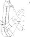
- Fig. 1 shows a schematic perspective illustration of a tank or central container 1 for a seed drill with a container wall 2 which surrounds a container volume 3.
- the container wall 2 is constructed in several pieces, with partial walls 2a, 2b, 2c.
- the partial walls 2a, 2b, 2c are assembled with one another, be it detachable or non-detachable, in order to provide the container volume 3, which is used to hold one or more granular materials such as seeds, fertilizers or the like, which are to be spread with the aid of a sowing or drilling machine .
- the container volume 3 is subdivided into a first partial volume 5 and a second partial volume 6 with the aid of a partition wall 4, which in the embodiment shown is constructed in several pieces.
- a first and a second container sump 7, 8 are assigned to the first and second sub-volumes 5, 6, via which the granular material received in the respective sub-volume can be applied, in particular to one or more sowing rows (not shown) via which the Material is then applied to the field.
- the first and the second container sump 7, 8 close to a first and a second base opening 9, 10, which are assigned to the first and the second partial volume 5, 6, respectively.
- the dividing wall 4 has a wall opening 11 which, in the exemplary embodiment shown, is arranged in an upright wall section 12 of the dividing wall 4 in such a way that the wall opening 11 extends as far as a kink area 13 on the bottom, in which a pivot axis 14 of a closure component 15 is formed, which in the in Fig. 1
- the illustration shown closes the first bottom opening 9.
- the closure component 15 can be pivoted about the pivot axis 14 in order to close the wall opening 11 and thereby expose the first bottom opening 9, as this Fig. 2 shows.
- a securing device 16 is provided which, in the embodiment shown, comprises wing screws by way of example.
- a displaceable wall section 4a of the dividing wall 4 is pivotably mounted, so that the volume ratio between the first and the second partial volume 5, 6 can be changed by pivoting the displaceable wall section 4a.
- a holding component 17 is provided (cf. Fig. 3 ).
Description
Die Erfindung betrifft einen Tank- oder Zentralbehälter für eine Sämaschine sowie eine Sämaschine.The invention relates to a tank or central container for a seed drill and a seed drill.
Ein Zentral- oder Tankbehälter für eine Sämaschine ist aus dem Dokument
Das Dokument
Aufgabe der Erfindung ist es, einen Tankbehälter für eine Sämaschine sowie eine Sämaschine anzugeben, bei denen der Tankbehälter für die Nutzung bei unterschiedlichen Arbeitsaufgaben flexibel anpassbar ist.The object of the invention is to provide a tank container for a seed drill and a seed drill in which the tank container can be flexibly adapted for use in different work tasks.
Zur Lösung ist ein Tankbehälter für eine Sämaschine nach dem unabhängigen Anspruch 1 geschaffen. Weiterhin ist eine Sämaschine nach dem nebengeordneten Anspruch 10 geschaffen. Ausgestaltungen sind Gegenstand von abhängigen Unteransprüchen.To solve this, a tank container for a seed drill according to independent claim 1 is created. Furthermore, a seed drill according to the
Nach einem Aspekt ist ein Tankbehälter für eine Sämaschine geschaffen, welcher eine Behälterwand, die ein Behältervolumen mehrseitig umgibt, und eine Teilungswand aufweist, die in dem Behältervolumen dieses in Teilvolumen aufteilend angeordnet ist, derart, dass ein erstes und ein zweites Teilvolumen gebildet sind, welche mittels der Teilungswand voneinander getrennt und eingerichtet sind, jeweils ein granulatartiges Material wie Saatkörner, Düngemittel oder dergleichen aufzunehmen. Ein erster Behältersumpf ist einer ersten Bodenöffnung im Bereich des ersten Teilvolumens zugeordnet und eingerichtet, das granulatartige Material in dem ersten Teilvolumen aus dem Behältervolumen auszubringen. Ein zweiter Behältersumpf ist einer zweiten Bodenöffnung im Bereich des zweiten Teilvolumens zugeordnet und eingerichtet, das granulatartige Material in dem zweiten Teilvolumen aus dem Behältervolumen auszubringen. In der Teilungswand ist eine Wandöffnung vorgesehen, durch welche hindurch das granulatartige Material von dem ersten in das zweite Teilvolumen und umgekehrt gelangen kann, wenn die Wandöffnung geöffnet oder freigegeben ist. Der Tankbehälter weist ein Verschlussbauteil auf, welches zwischen einer ersten und einer zweiten Stellung verlagerbar ist, derart, dass das Verschlussbauteil beim Verlagern von der ersten in die zweite Stellung die erste Bodenöffnung öffnet und die Wandöffnung verschließt und beim Verlagern von der zweiten in die erste Stellung die Wandöffnung öffnet und die erste Bodenöffnung verschließt.According to one aspect, a tank container for a seed drill is provided, which has a container wall that surrounds a container volume on several sides, and a partition wall which is arranged in the container volume dividing it into partial volumes, such that a first and a second partial volume are formed by means of the partition wall from each other are separated and set up to receive a granular material such as seeds, fertilizers or the like. A first container sump is assigned to a first bottom opening in the area of the first partial volume and is set up to discharge the granular material in the first partial volume from the container volume. A second container sump is assigned to a second bottom opening in the region of the second partial volume and is set up to discharge the granular material in the second partial volume from the container volume. A wall opening is provided in the dividing wall, through which the granular material can pass from the first into the second partial volume and vice versa when the wall opening is opened or released. Of the The tank container has a closure component which can be displaced between a first and a second position, such that the closure component opens the first bottom opening and closes the wall opening when it is moved from the first to the second position and the wall opening when it is moved from the second to the first position Wall opening opens and the first floor opening closes.
Weiterhin ist eine Sämaschine mit einem solchen Tankbehälter geschaffen.Furthermore, a seed drill with such a tank container is created.
Der Tankbehälter dient bei der Sämaschine als zentraler Behälter zur Aufnahme granulatartigen Materials, welches aus dem Zentralbehälter regelmäßig zu mehreren Säreihen transportiert wird, die jeweils dazu dienen, das granulatartige Material auf und in den Erdboden auszubringen, insbesondere in eine Saatfurche. Der Tankbehälter verfügt mit dem ersten und dem zweiten Teilvolumen über Behälterteilvolumen, die mit dem gleichen oder unterschiedlichen granulatartigen Material befüllt werden können. Über einen jeweils zugeordneten Behältersumpf kann das granulatartige Material aus den Teilvolumen ausgebracht werden. Beispielsweise können das erste und das zweite Teilvolumen unterschiedliche Saatkörner aufnehmen. In einer anderen Betriebsart nimmt das erste Teilvolumen Saatkörner auf, wohingegen in dem zweiten Teilvolumen ein Düngemittel aufgenommen ist, welches zusammen mit den Saatkörnern dosiert auszubringen ist.The tank container is used in the seed drill as a central container for receiving granular material, which is regularly transported from the central container to several rows of seeds, each of which is used to spread the granular material on and into the ground, especially in a seed furrow. With the first and second partial volumes, the tank container has partial container volumes which can be filled with the same or different granular material. The granular material can be discharged from the partial volume via a respectively assigned container sump. For example, the first and the second partial volume can accommodate different seeds. In another operating mode, the first partial volume receives seeds, whereas the second partial volume contains a fertilizer which is to be applied in a metered manner together with the seeds.
Der Tankbehälter kann auf einer Sämaschine angeordnet sein, die als Anhängefahrzeug ausgestaltet ist. In einer alternativen Ausgestaltung kann der Tank- oder Zentralbehälter von einem Traktor getragen werden.The tank container can be arranged on a seed drill which is designed as a trailer vehicle. In an alternative embodiment, the tank or central container can be carried by a tractor.
Die vorgesehen Verlagerbarkeit des Verschlussbauteils ermöglicht es, den Tankbehälter für unterschiedliche Betriebsarten der Sämaschine herzurichten. Ist das Verschlussbauteil so angeordnet, dass hiermit die erste Bodenöffnung in dem ersten Teilvolumen geschlossen ist, ist hierdurch die Wandöffnung in der Teilungswand freigegeben, sodass das erste und das zweite Teilvolumen hierüber miteinander verbunden sind, derart, dass das granulatartige Material von dem einen in das andere Teilvolumen gelangen kann. Das Ausbringen des granulatartigen Materials kann dann über die zweite Bodenöffnung erfolgen. Verschließt das Verschlussbauteil die Wandöffnung, sind das erste und das zweite Teilvolumen vollständig voneinander getrennt, sodass hierin jeweils ein granulatartiges Material aufgenommen werden kann, insbesondere unterschiedliche Materialien. Die Abgabe der granulatartigen Materialien kann dann aus dem ersten Teilvolumen über die erste Bodenöffnung und aus dem zweiten Teilvolumen über die zweite Bodenöffnung erfolgen.The intended displaceability of the closure component makes it possible to prepare the tank container for different operating modes of the seed drill. If the closure component is arranged in such a way that this closes the first bottom opening in the first partial volume, the wall opening in the dividing wall is thereby released, so that the first and second partial volumes are connected to one another in such a way that the granular material is transferred from one to the other can reach other partial volumes. The granular material can then be discharged through the second opening in the bottom. If the closure component closes the wall opening, the first and second partial volumes are completely separated from one another, so that a granulate-like material, in particular different materials, can be received therein. The delivery of the granular materials can then take place from the first partial volume via the first base opening and from the second partial volume via the second base opening.
Das Verschlussbauteil ist mittels Schwenken zwischen der ersten und der zweiten Stellung verlagerbar. Das Verschlussbauteil ist hierbei mindestens zwischen einer ersten und einer zweiten Schwenkstellung verlagerbar, in denen das Verschlussbauteil selbst entweder die Wandöffnung oder die erste Bodenöffnung verschließt.The closure component can be displaced by pivoting between the first and the second position. The closure component can be displaced at least between a first and a second pivot position in which the closure component itself closes either the wall opening or the first bottom opening.
Das Verschlussbauteil ist in einem Eckbereich schwenkbar gelagert , in welchem die Teilungswand an einen Boden der Behälterwand stößt. Hierbei ist die Schwenkachse fürs Schwenken des Verschlussbauteils in dem Eckbereich angeordnet.The closure component is pivotably mounted in a corner area in which the dividing wall abuts a bottom of the container wall. Here, the pivot axis for pivoting the closure component is arranged in the corner area.
In dem Eckbereich können Wandabschnitte aneinanderstoßen, die den ersten und den zweiten Behältersumpf begrenzen. Alternativ können Verlängerungen solcher Wandabschnitte des ersten und des zweiten Behältersumpfes in dem Eckbereich aneinander stoßend angeordnet sein.In the corner area, wall sections that delimit the first and the second container sump can abut one another. Alternatively, extensions of such wall sections of the first and the second container sump can be arranged in abutting relationship in the corner area.
In dem Eckbereich können die erste Bodenöffnung und die Wandöffnung benachbart zueinander angeordnet sein. Insbesondere die Wandöffnung kann sich bei dieser oder anderen Ausführungsformen bis zum Eckbereich erstrecken, sodass bei offener Wandöffnung ein Übergang des granulatartigen Materials zwischen dem ersten und dem zweiten Teilvolumen erleichtert ist.In the corner area, the first floor opening and the wall opening can be arranged adjacent to one another. In particular, the wall opening can extend as far as the corner area in this or other embodiments, so that when the wall opening is open, a transition of the granular material between the first and the second partial volume is facilitated.
Die Wandöffnung kann in einem aufrechtstehenden Wandabschnitt der Teilungswand angeordnet sein. Der aufrecht stehende Wandabschnitt kann vertikal ausgerichtet sein.The wall opening can be arranged in an upright wall section of the dividing wall. The upright wall section can be oriented vertically.
Die erste Bodenöffnung und die Wandöffnung können wenigstens hinsichtlich eines Öffnungsparameters aus der folgende Gruppe gleich ausgebildet sein: Umfangsform und Öffnungsfläche. Eine gleichartige Ausbildung der Öffnungen unterstützt ein möglichst dichtes Abschließen der jeweiligen Öffnung durch das Verschlussbauteil.The first bottom opening and the wall opening can be designed to be the same, at least with regard to one opening parameter from the following group: circumferential shape and opening area. A similar design of the openings supports the closing of the respective opening as tightly as possible by the closure component.
Das Verschlussbauteil kann wenigstens einer der folgenden Ausgestaltungen entsprechend ausgeführt sein: In der ersten Stellung überlappt das Verschlussbauteil zum Dichten um die erste Bodenöffnung herum mehrseitig mit einem die erste Bodenöffnung umgebenden Rand; und in der zweiten Stellung überlappt das Verschlussbauteil zum Dichten um die Wandöffnung herum mehrseitig mit einem die Wandöffnung umgebenden Rand. In dem randseitigen Überlappungsbereich kann ein Flachabschnitt des Verschlussbauteils eben auf einer ebenen Auflagefläche im Bereich des umgebenden Rands der jeweiligen Öffnung aufliegen. Im Überlappungsbereich kann eine Dichtungseinrichtung vorgesehen sein, beispielweise in Form einer mehrseitig oder allseitig umlaufenden Dichtung, zum Beispiel einer Kunststoff- oder Gummidichtung. In einer alternativen Ausführungsform liegen ebene Metallflächen des Verschlussbauteils einerseits und des umgebenen Rands der jeweiligen Öffnung andererseits eben aufeinander. In einer Ausgestaltung ist das Verschlussbauteil zumindest stückweise aus einem Kunststoffmaterial.The closure component can be designed according to at least one of the following configurations: In the first position, the closure component overlaps on several sides with an edge surrounding the first base opening for sealing around the first base opening; and in the second position the closure member overlaps to seal around the wall opening around several sides with an edge surrounding the wall opening. In the edge-side overlapping area, a flat section of the closure component can rest flat on a flat support surface in the area of the surrounding edge of the respective opening. A sealing device can be provided in the overlapping area, for example in the form of a seal that encircles multiple or all sides, for example a plastic or rubber seal. In an alternative embodiment, flat metal surfaces of the closure component on the one hand and the surrounding edge of the respective opening on the other hand lie flat on top of one another. In one embodiment, the closure component is at least partially made of a plastic material.
Das Verschlussbauteil kann mit einer Verschlussplatte gebildet sein.The closure component can be formed with a closure plate.
Dem Verschlussbauteil kann eine Sicherungseinrichtung zugeordnet sein, mit der das Verschlussbauteil in der ersten und / oder der zweiten Stellung gegen ein unbeabsichtigtes Lösen aus der jeweiligen Stellung gesichert ist. Die Sicherungseinrichtung kann beispielweise Schrauben umfassen, insbesondere Flügelschrauben, mit denen das Verschlussbauteil in der jeweiligen Stellung gegen ein unbeabsichtigtes Verlagern gesichert werden kann. Auch ein magnetischer Sicherungsmechanismus kann vorgesehen sein, um das Verschlussbauteil in der jeweiligen Stellung zu halten.A safety device can be assigned to the locking component, with which the locking component is secured in the first and / or the second position against unintentional release from the respective position. The securing device can, for example, comprise screws, in particular wing screws, with which the closure component can be secured against unintentional displacement in the respective position. A magnetic securing mechanism can also be provided in order to hold the locking component in the respective position.
An dem Verschlussbauteil kann eine Griffeinrichtung angeordnet sein. Die Griffeinrichtung kann von einem Nutzer gegriffen werden, um das Verschlussbauteil zwischen der ersten und der zweiten Stellung zu verlagern, insbesondere zu schwenken.A handle device can be arranged on the closure component. The handle device can be gripped by a user in order to displace the closure component between the first and the second position, in particular to pivot it.
Die Teilungswand weist einen verlagerbaren Wandabschnitt auf, mittels dessen Verlagerung zwischen einer ersten und einer zweiten Verlagerungsstellung ein Volumenverhältnis zwischen dem ersten und dem zweiten Teilvolumen veränderbar ist. Der verlagerbare Wandabschnitt kann zwischen der ersten und der zweiten Verlagerungsstellung verschwenkbar sein. Der verlagerbare Wandabschnitt bildet einen oberen Teil der Teilungswand , welcher benachbart zur deckseitigen Öffnung des Tank- oder Zentralbehälters angeordnet ist. Es können mehr als zwei Verlagerungsstellungen für den verlagerbaren Wandabschnitt vorgesehen sein, um weitere Volumenverhältnisse zwischen ersten und dem zweiten Teilvolumen einzustellen. Mehr als ein Wandabschnitt der Teilungswand können zum Einstellen der Volumenverhältnisse verlagerbar sein.The dividing wall has a displaceable wall section, by means of which displacement between a first and a second displacement position a volume ratio between the first and the second partial volume can be changed. The displaceable wall section can be pivoted between the first and the second displacement position. The displaceable wall section forms an upper part of the dividing wall, which is arranged adjacent to the opening on the top of the tank or central container. More than two displacement positions can be provided for the displaceable wall section in order to set further volume ratios between the first and the second partial volume. More than one wall section of the dividing wall can be displaceable for setting the volume ratios.
Im Folgenden werden weitere Ausführungsbeispiele unter Bezugnahme auf Figuren einer Zeichnung näher erläutert. Hierbei zeigen:
- Fig. 1
- eine schematische perspektivische Darstellung eines Tank- oder Zentralbehälters für eine Sämaschine im Schnitt, wobei mittels eines Verschlussbauteils eine erste Bodenöffnung zu einem ersten Behältersumpf hin verschlossen ist;
- Fig. 2
- eine schematische perspektivische Darstellung des Tankbehälters aus
Fig. 1 im Schnitt, wobei mittels des Verschlussbauteils nun eine Wandöffnung in einer Teilungswand verschlossen ist; und - Fig. 3
- eine schematische perspektivische Darstellung des Tankbehälters aus
Fig. 1 im Schnitt, wobei bei geschlossener Bodenöffnung ein verlagerbarer Wandabschnitt der Teilungswand verlagert ist.
- Fig. 1
- a schematic perspective illustration of a tank or central container for a seed drill in section, with a first bottom opening being closed to a first container sump by means of a closure component;
- Fig. 2
- a schematic perspective view of the tank container from
Fig. 1 in section, with a wall opening in a partition wall now being closed by means of the closing component; and - Fig. 3
- a schematic perspective view of the tank container from
Fig. 1 in section, with a displaceable wall section of the partition wall being displaced when the bottom opening is closed.
Das Behältervolumen 3 wird mit Hilfe einer Teilungswand 4, die in der gezeigten Ausführungsform mehrstückig ausgeführt ist, in ein erstes Teilvolumen 5 und ein zweites Teilvolumen 6 unterteilt. Dem ersten und dem zweiten Teilvolumen 5, 6 ist ein erster und ein zweiter Behältersumpf 7, 8 zugeordnet, über den das in dem jeweiligen Teilvolumen aufgenommen granulatartige Material ausgebracht werden kann, insbesondere hin zu einer oder mehreren Säreihen (nicht dargestellt), über die das Material dann auf das Feld ausgebracht wird. Hierzu schließen der erste und der zweite Behältersumpf 7, 8 an eine erste und eine zweite Bodenöffnung 9, 10, die dem ersten beziehungsweise dem zweiten Teilvolumen 5, 6 zugeordnet sind.The
Die Teilungswand 4 weist eine Wandöffnung 11 auf, die bei dem gezeigten Ausführungsbeispiel in einem aufrecht stehenden Wandabschnitt 12 der Teilungswand 4 angeordnet ist, derart, dass sich die Wandöffnung 11 bis zu einem bodenseitigen Knickbereich 13 erstreckt, in welchem eine Schwenkachse 14 eines Verschlussbauteils 15 ausgebildet ist, welches in der in
Gemäß
Die in der vorstehenden Beschreibung, den Ansprüchen und der Zeichnung offenbarten Merkmale können sowohl einzeln als auch in beliebiger Kombination für die Verwirklichung der verschiedenen Ausführungen von Bedeutung sein.The features disclosed in the above description, the claims and the drawing can be important both individually and in any combination for the implementation of the various embodiments.
Claims (10)
- A hopper (1) for a seed drill, having:- a hopper wall (2) surrounding a hopper volume (3) on multiple sides;- a partition wall (4), which is arranged in the hopper volume (3), separating it into partial volumes, such that a first and a second partial volume (5, 6) are formed, which are separated from each other by means of the partition wall (4), and are each configured for receiving a granular material such as seed grains, fertilizers or the like;- a first sump (7), which is associated with a first bottom opening (9) in the region of the first partial volume (5) and is configured for discharging the granular material in the first partial volume (5) from the hopper volume;- a second sump (8), which is associated with a second bottom opening (10) in the region of the second partial volume (6) and is configured for discharging the granular material in the second partial volume (6) from the hopper volume (3);- a wall opening (11) in the partition wall (4), through which the granular material can pass from the first to the second partial volume (5, 6) and vice versa when the wall opening (11) is open; and- a closure member (15), which is supported in a pivotable manner in a corner region (13) in which the partition wall (4) meets a bottom of the hopper wall (2), and which can be pivoted between a first and a second position, such that the closure member (15)characterized in that the partition wall (4) has a displaceable wall section (4a), which forms an upper part of the partition wall (4), which upper part is arranged adjacent to an opening of the hopper (1) located on the deck side, and which, by means of displacing it between a first and a second displacement position, can change a volume ratio between the first and the second partial volume (5, 6).- opens the first bottom opening (9) and closes the wall opening (11) when it is displaced from the first to the second position, and- opens the wall opening (11) and closes the first bottom opening (9) when it is displaced from the second to the first position;
- The hopper (1) according to claim 1, characterized in that wall sections meet in the corner region (13), which wall sections delimit the first and the second sump (7, 8).
- The hopper (1) according to claim 1 or 2, characterized in that the first bottom opening (9) and the wall opening (11) are arranged adjacent to each other in the corner region (13).
- The hopper (1) according to at least one of the preceding claims, characterized in that the wall opening (11) is arranged in an upright wall section (12) of the partition wall (4).
- The hopper (1) according to at least one of the preceding claims, characterized in that the first bottom opening (9) and the wall opening (11) are designed identically at least with respect to one opening parameter from the following group: circumferential shape and opening area.
- The hopper (1) according to at least one of the preceding claims, characterized in that the closure member (15) is designed according to at least one of the following embodiments:- in the first position, the closure member (15) overlaps an edge surrounding the first bottom opening (9) on multiple sides for creating a seal around the first floor opening (9); and- in the second position, the closure member (15) overlaps an edge surrounding the wall opening (11) on multiple sides for creating a seal around the wall opening (11).
- The hopper (1) according to at least one of the preceding claims, characterized in that the closure member (15) is formed having a closure plate.
- The hopper (1) according to at least one of the preceding claims, characterized in that the closure member (15) is associated with a securing device (16) with which the closure member (15) in the first and/or the second position can be secured against an unintentional release from the respective position.
- The hopper (1) according to at least one of the preceding claims, characterized in that a handle device is arranged on the closure member (15).
- A seed drill, with a hopper (1) according to at least one of the preceding claims.
Priority Applications (3)
| Application Number | Priority Date | Filing Date | Title |
|---|---|---|---|
| EP18212549.2A EP3666052B1 (en) | 2018-12-14 | 2018-12-14 | Hopper for a sowing machine and sowing machine |
| PL18212549T PL3666052T3 (en) | 2018-12-14 | 2018-12-14 | Hopper for a sowing machine and sowing machine |
| ES18212549T ES2869702T3 (en) | 2018-12-14 | 2018-12-14 | Tank container for a seeder and seeder machine |
Applications Claiming Priority (1)
| Application Number | Priority Date | Filing Date | Title |
|---|---|---|---|
| EP18212549.2A EP3666052B1 (en) | 2018-12-14 | 2018-12-14 | Hopper for a sowing machine and sowing machine |
Publications (2)
| Publication Number | Publication Date |
|---|---|
| EP3666052A1 EP3666052A1 (en) | 2020-06-17 |
| EP3666052B1 true EP3666052B1 (en) | 2021-03-03 |
Family
ID=64665539
Family Applications (1)
| Application Number | Title | Priority Date | Filing Date |
|---|---|---|---|
| EP18212549.2A Active EP3666052B1 (en) | 2018-12-14 | 2018-12-14 | Hopper for a sowing machine and sowing machine |
Country Status (3)
| Country | Link |
|---|---|
| EP (1) | EP3666052B1 (en) |
| ES (1) | ES2869702T3 (en) |
| PL (1) | PL3666052T3 (en) |
Family Cites Families (5)
| Publication number | Priority date | Publication date | Assignee | Title |
|---|---|---|---|---|
| US3432064A (en) * | 1967-12-15 | 1969-03-11 | Deere & Co | Adjustable partition for combination grain and fertilizer hopper |
| GB1517768A (en) | 1975-12-24 | 1978-07-12 | Rasmussen As E | System for localizing a spot along a conductor in which an impedance change such as a break or short circuit occurs |
| SE450189B (en) * | 1984-02-07 | 1987-06-15 | Oeverums Bruk Ab | DEVICE FOR A COMBIMAN MADE FOR THE DIFFERENT DISTRIBUTION OF SEEDS AND ARTICLES |
| US5927217A (en) * | 1997-06-16 | 1999-07-27 | Conserva Pak Seeding Systems | Metering particulate material |
| US7104207B2 (en) * | 2004-04-29 | 2006-09-12 | Cnh America Llc | Air seeder tank arrangement |
-
2018
- 2018-12-14 ES ES18212549T patent/ES2869702T3/en active Active
- 2018-12-14 PL PL18212549T patent/PL3666052T3/en unknown
- 2018-12-14 EP EP18212549.2A patent/EP3666052B1/en active Active
Non-Patent Citations (1)
| Title |
|---|
| None * |
Also Published As
| Publication number | Publication date |
|---|---|
| EP3666052A1 (en) | 2020-06-17 |
| ES2869702T3 (en) | 2021-10-25 |
| PL3666052T3 (en) | 2021-09-13 |
Similar Documents
| Publication | Publication Date | Title |
|---|---|---|
| DE19522229A1 (en) | Sowing device with modular dosing device | |
| DE202014009404U1 (en) | Unit for taking a sample of material to be spread from a distributor and pneumatic distributor and receiving device of such a unit | |
| DE102018204532A1 (en) | Service system for a vehicle air conditioning system | |
| EP0094583B1 (en) | Feed control for a seed or fertiliser distributor | |
| DE69701887T3 (en) | MACHINE FOR SPREADING GRAINY SUBSTANCES, ESPECIALLY FERTILIZER | |
| DE102007045358A1 (en) | Zentraldosierer | |
| EP3666052B1 (en) | Hopper for a sowing machine and sowing machine | |
| DE1904273C3 (en) | Storage container for a seed drill | |
| EP3836773A1 (en) | Dispensing machine for a granular product | |
| DE202007009302U1 (en) | seeder | |
| DE102014224058A1 (en) | Agricultural machine with a tool-free removable reservoir for granular material | |
| DE1945076C3 (en) | Spreader for granular or powdery grit | |
| DE4411000C1 (en) | Metering device for seed, fertiliser and the like | |
| EP0216058B1 (en) | Machine for spreading granular material | |
| DE4104685C1 (en) | ||
| DE202018006598U1 (en) | Distributor for granular material | |
| EP3818804B1 (en) | Supply device for a grain separating device | |
| DE139528C (en) | ||
| EP3979781B1 (en) | Pneumatic seed or fertiliser distribution machine | |
| DE102010000298A1 (en) | Zweischeibenstreuer | |
| DE102018107833B4 (en) | Feed mixer with attachment for mixing containers | |
| DE102020001138A1 (en) | Application device for substances on and / or in a soil | |
| EP2052595A1 (en) | Sowing machine | |
| DE102008017944A1 (en) | Sowing machine i.e. large surface single grain sowing machine, has supply container with extended container and/or container area, where material in container area slides into discharge area attached to dosing and/or sorting unit | |
| DE102022117498A1 (en) | Device for dosing and/or mixing pourable foods, especially spices |
Legal Events
| Date | Code | Title | Description |
|---|---|---|---|
| PUAI | Public reference made under article 153(3) epc to a published international application that has entered the european phase |
Free format text: ORIGINAL CODE: 0009012 |
|
| STAA | Information on the status of an ep patent application or granted ep patent |
Free format text: STATUS: THE APPLICATION HAS BEEN PUBLISHED |
|
| STAA | Information on the status of an ep patent application or granted ep patent |
Free format text: STATUS: REQUEST FOR EXAMINATION WAS MADE |
|
| AK | Designated contracting states |
Kind code of ref document: A1 Designated state(s): AL AT BE BG CH CY CZ DE DK EE ES FI FR GB GR HR HU IE IS IT LI LT LU LV MC MK MT NL NO PL PT RO RS SE SI SK SM TR |
|
| AX | Request for extension of the european patent |
Extension state: BA ME |
|
| 17P | Request for examination filed |
Effective date: 20200604 |
|
| RBV | Designated contracting states (corrected) |
Designated state(s): AL AT BE BG CH CY CZ DE DK EE ES FI FR GB GR HR HU IE IS IT LI LT LU LV MC MK MT NL NO PL PT RO RS SE SI SK SM TR |
|
| GRAP | Despatch of communication of intention to grant a patent |
Free format text: ORIGINAL CODE: EPIDOSNIGR1 |
|
| STAA | Information on the status of an ep patent application or granted ep patent |
Free format text: STATUS: GRANT OF PATENT IS INTENDED |
|
| RIC1 | Information provided on ipc code assigned before grant |
Ipc: A01C 15/00 20060101AFI20200911BHEP Ipc: A01C 7/06 20060101ALN20200911BHEP |
|
| INTG | Intention to grant announced |
Effective date: 20200929 |
|
| GRAS | Grant fee paid |
Free format text: ORIGINAL CODE: EPIDOSNIGR3 |
|
| STAA | Information on the status of an ep patent application or granted ep patent |
Free format text: STATUS: GRANT OF PATENT IS INTENDED |
|
| GRAA | (expected) grant |
Free format text: ORIGINAL CODE: 0009210 |
|
| STAA | Information on the status of an ep patent application or granted ep patent |
Free format text: STATUS: THE PATENT HAS BEEN GRANTED |
|
| AK | Designated contracting states |
Kind code of ref document: B1 Designated state(s): AL AT BE BG CH CY CZ DE DK EE ES FI FR GB GR HR HU IE IS IT LI LT LU LV MC MK MT NL NO PL PT RO RS SE SI SK SM TR |
|
| REG | Reference to a national code |
Ref country code: GB Ref legal event code: FG4D Free format text: NOT ENGLISH |
|
| REG | Reference to a national code |
Ref country code: AT Ref legal event code: REF Ref document number: 1366158 Country of ref document: AT Kind code of ref document: T Effective date: 20210315 Ref country code: CH Ref legal event code: EP |
|
| REG | Reference to a national code |
Ref country code: DE Ref legal event code: R096 Ref document number: 502018004122 Country of ref document: DE |
|
| REG | Reference to a national code |
Ref country code: IE Ref legal event code: FG4D Free format text: LANGUAGE OF EP DOCUMENT: GERMAN |
|
| REG | Reference to a national code |
Ref country code: SE Ref legal event code: TRGR |
|
| REG | Reference to a national code |
Ref country code: RO Ref legal event code: EPE |
|
| REG | Reference to a national code |
Ref country code: LT Ref legal event code: MG9D |
|
| PG25 | Lapsed in a contracting state [announced via postgrant information from national office to epo] |
Ref country code: LT Free format text: LAPSE BECAUSE OF FAILURE TO SUBMIT A TRANSLATION OF THE DESCRIPTION OR TO PAY THE FEE WITHIN THE PRESCRIBED TIME-LIMIT Effective date: 20210303 Ref country code: NO Free format text: LAPSE BECAUSE OF FAILURE TO SUBMIT A TRANSLATION OF THE DESCRIPTION OR TO PAY THE FEE WITHIN THE PRESCRIBED TIME-LIMIT Effective date: 20210603 Ref country code: HR Free format text: LAPSE BECAUSE OF FAILURE TO SUBMIT A TRANSLATION OF THE DESCRIPTION OR TO PAY THE FEE WITHIN THE PRESCRIBED TIME-LIMIT Effective date: 20210303 Ref country code: GR Free format text: LAPSE BECAUSE OF FAILURE TO SUBMIT A TRANSLATION OF THE DESCRIPTION OR TO PAY THE FEE WITHIN THE PRESCRIBED TIME-LIMIT Effective date: 20210604 Ref country code: FI Free format text: LAPSE BECAUSE OF FAILURE TO SUBMIT A TRANSLATION OF THE DESCRIPTION OR TO PAY THE FEE WITHIN THE PRESCRIBED TIME-LIMIT Effective date: 20210303 Ref country code: BG Free format text: LAPSE BECAUSE OF FAILURE TO SUBMIT A TRANSLATION OF THE DESCRIPTION OR TO PAY THE FEE WITHIN THE PRESCRIBED TIME-LIMIT Effective date: 20210603 |
|
| REG | Reference to a national code |
Ref country code: NL Ref legal event code: MP Effective date: 20210303 |
|
| PG25 | Lapsed in a contracting state [announced via postgrant information from national office to epo] |
Ref country code: RS Free format text: LAPSE BECAUSE OF FAILURE TO SUBMIT A TRANSLATION OF THE DESCRIPTION OR TO PAY THE FEE WITHIN THE PRESCRIBED TIME-LIMIT Effective date: 20210303 Ref country code: LV Free format text: LAPSE BECAUSE OF FAILURE TO SUBMIT A TRANSLATION OF THE DESCRIPTION OR TO PAY THE FEE WITHIN THE PRESCRIBED TIME-LIMIT Effective date: 20210303 |
|
| PG25 | Lapsed in a contracting state [announced via postgrant information from national office to epo] |
Ref country code: NL Free format text: LAPSE BECAUSE OF FAILURE TO SUBMIT A TRANSLATION OF THE DESCRIPTION OR TO PAY THE FEE WITHIN THE PRESCRIBED TIME-LIMIT Effective date: 20210303 |
|
| REG | Reference to a national code |
Ref country code: ES Ref legal event code: FG2A Ref document number: 2869702 Country of ref document: ES Kind code of ref document: T3 Effective date: 20211025 |
|
| PG25 | Lapsed in a contracting state [announced via postgrant information from national office to epo] |
Ref country code: SM Free format text: LAPSE BECAUSE OF FAILURE TO SUBMIT A TRANSLATION OF THE DESCRIPTION OR TO PAY THE FEE WITHIN THE PRESCRIBED TIME-LIMIT Effective date: 20210303 Ref country code: EE Free format text: LAPSE BECAUSE OF FAILURE TO SUBMIT A TRANSLATION OF THE DESCRIPTION OR TO PAY THE FEE WITHIN THE PRESCRIBED TIME-LIMIT Effective date: 20210303 |
|
| PG25 | Lapsed in a contracting state [announced via postgrant information from national office to epo] |
Ref country code: IS Free format text: LAPSE BECAUSE OF FAILURE TO SUBMIT A TRANSLATION OF THE DESCRIPTION OR TO PAY THE FEE WITHIN THE PRESCRIBED TIME-LIMIT Effective date: 20210703 Ref country code: PT Free format text: LAPSE BECAUSE OF FAILURE TO SUBMIT A TRANSLATION OF THE DESCRIPTION OR TO PAY THE FEE WITHIN THE PRESCRIBED TIME-LIMIT Effective date: 20210705 Ref country code: SK Free format text: LAPSE BECAUSE OF FAILURE TO SUBMIT A TRANSLATION OF THE DESCRIPTION OR TO PAY THE FEE WITHIN THE PRESCRIBED TIME-LIMIT Effective date: 20210303 |
|
| REG | Reference to a national code |
Ref country code: DE Ref legal event code: R097 Ref document number: 502018004122 Country of ref document: DE |
|
| PLBE | No opposition filed within time limit |
Free format text: ORIGINAL CODE: 0009261 |
|
| STAA | Information on the status of an ep patent application or granted ep patent |
Free format text: STATUS: NO OPPOSITION FILED WITHIN TIME LIMIT |
|
| PG25 | Lapsed in a contracting state [announced via postgrant information from national office to epo] |
Ref country code: DK Free format text: LAPSE BECAUSE OF FAILURE TO SUBMIT A TRANSLATION OF THE DESCRIPTION OR TO PAY THE FEE WITHIN THE PRESCRIBED TIME-LIMIT Effective date: 20210303 Ref country code: AL Free format text: LAPSE BECAUSE OF FAILURE TO SUBMIT A TRANSLATION OF THE DESCRIPTION OR TO PAY THE FEE WITHIN THE PRESCRIBED TIME-LIMIT Effective date: 20210303 |
|
| 26N | No opposition filed |
Effective date: 20211206 |
|
| REG | Reference to a national code |
Ref country code: AT Ref legal event code: PC Ref document number: 1366158 Country of ref document: AT Kind code of ref document: T Owner name: KVERNELAND GROUP SOEST GMBH, DE Effective date: 20220411 |
|
| REG | Reference to a national code |
Ref country code: ES Ref legal event code: PC2A Owner name: KVERNELAND GROUP SOEST GMBH Effective date: 20220525 |
|
| PG25 | Lapsed in a contracting state [announced via postgrant information from national office to epo] |
Ref country code: IS Free format text: LAPSE BECAUSE OF FAILURE TO SUBMIT A TRANSLATION OF THE DESCRIPTION OR TO PAY THE FEE WITHIN THE PRESCRIBED TIME-LIMIT Effective date: 20210703 |
|
| PG25 | Lapsed in a contracting state [announced via postgrant information from national office to epo] |
Ref country code: MC Free format text: LAPSE BECAUSE OF FAILURE TO SUBMIT A TRANSLATION OF THE DESCRIPTION OR TO PAY THE FEE WITHIN THE PRESCRIBED TIME-LIMIT Effective date: 20210303 |
|
| REG | Reference to a national code |
Ref country code: CH Ref legal event code: PL |
|
| REG | Reference to a national code |
Ref country code: GB Ref legal event code: 732E Free format text: REGISTERED BETWEEN 20220707 AND 20220713 |
|
| REG | Reference to a national code |
Ref country code: DE Ref legal event code: R081 Ref document number: 502018004122 Country of ref document: DE Owner name: KVERNELAND GROUP SOEST GMBH, DE Free format text: FORMER OWNER: KVERNELAND A/S, KLEPP STASJON, NO |
|
| REG | Reference to a national code |
Ref country code: BE Ref legal event code: MM Effective date: 20211231 |
|
| PG25 | Lapsed in a contracting state [announced via postgrant information from national office to epo] |
Ref country code: LU Free format text: LAPSE BECAUSE OF NON-PAYMENT OF DUE FEES Effective date: 20211214 Ref country code: IE Free format text: LAPSE BECAUSE OF NON-PAYMENT OF DUE FEES Effective date: 20211214 |
|
| PG25 | Lapsed in a contracting state [announced via postgrant information from national office to epo] |
Ref country code: BE Free format text: LAPSE BECAUSE OF NON-PAYMENT OF DUE FEES Effective date: 20211231 |
|
| PG25 | Lapsed in a contracting state [announced via postgrant information from national office to epo] |
Ref country code: LI Free format text: LAPSE BECAUSE OF NON-PAYMENT OF DUE FEES Effective date: 20211231 Ref country code: CH Free format text: LAPSE BECAUSE OF NON-PAYMENT OF DUE FEES Effective date: 20211231 |
|
| PGFP | Annual fee paid to national office [announced via postgrant information from national office to epo] |
Ref country code: PL Payment date: 20221206 Year of fee payment: 5 |
|
| PGFP | Annual fee paid to national office [announced via postgrant information from national office to epo] |
Ref country code: ES Payment date: 20230228 Year of fee payment: 5 |
|
| PG25 | Lapsed in a contracting state [announced via postgrant information from national office to epo] |
Ref country code: CY Free format text: LAPSE BECAUSE OF FAILURE TO SUBMIT A TRANSLATION OF THE DESCRIPTION OR TO PAY THE FEE WITHIN THE PRESCRIBED TIME-LIMIT Effective date: 20210303 |
|
| P01 | Opt-out of the competence of the unified patent court (upc) registered |
Effective date: 20230525 |
|
| PG25 | Lapsed in a contracting state [announced via postgrant information from national office to epo] |
Ref country code: HU Free format text: LAPSE BECAUSE OF FAILURE TO SUBMIT A TRANSLATION OF THE DESCRIPTION OR TO PAY THE FEE WITHIN THE PRESCRIBED TIME-LIMIT; INVALID AB INITIO Effective date: 20181214 |
|
| PG25 | Lapsed in a contracting state [announced via postgrant information from national office to epo] |
Ref country code: SI Free format text: LAPSE BECAUSE OF FAILURE TO SUBMIT A TRANSLATION OF THE DESCRIPTION OR TO PAY THE FEE WITHIN THE PRESCRIBED TIME-LIMIT Effective date: 20210303 |
|
| PGFP | Annual fee paid to national office [announced via postgrant information from national office to epo] |
Ref country code: GB Payment date: 20231220 Year of fee payment: 6 |
|
| PGFP | Annual fee paid to national office [announced via postgrant information from national office to epo] |
Ref country code: SE Payment date: 20231220 Year of fee payment: 6 Ref country code: RO Payment date: 20231205 Year of fee payment: 6 Ref country code: IT Payment date: 20231228 Year of fee payment: 6 Ref country code: FR Payment date: 20231222 Year of fee payment: 6 Ref country code: DE Payment date: 20231214 Year of fee payment: 6 Ref country code: CZ Payment date: 20231206 Year of fee payment: 6 Ref country code: AT Payment date: 20231221 Year of fee payment: 6 |
|
| PGFP | Annual fee paid to national office [announced via postgrant information from national office to epo] |
Ref country code: PL Payment date: 20231201 Year of fee payment: 6 |