EP3665993B1 - Auslösung von harq-ack-rückkopplung für einen downlink-schlitzsatz - Google Patents
Auslösung von harq-ack-rückkopplung für einen downlink-schlitzsatz Download PDFInfo
- Publication number
- EP3665993B1 EP3665993B1 EP17920831.9A EP17920831A EP3665993B1 EP 3665993 B1 EP3665993 B1 EP 3665993B1 EP 17920831 A EP17920831 A EP 17920831A EP 3665993 B1 EP3665993 B1 EP 3665993B1
- Authority
- EP
- European Patent Office
- Prior art keywords
- control signal
- slot set
- downlink slot
- uci
- harq
- Prior art date
- Legal status (The legal status is an assumption and is not a legal conclusion. Google has not performed a legal analysis and makes no representation as to the accuracy of the status listed.)
- Active
Links
Images


Classifications
-
- H—ELECTRICITY
- H04—ELECTRIC COMMUNICATION TECHNIQUE
- H04L—TRANSMISSION OF DIGITAL INFORMATION, e.g. TELEGRAPHIC COMMUNICATION
- H04L1/00—Arrangements for detecting or preventing errors in the information received
- H04L1/12—Arrangements for detecting or preventing errors in the information received by using return channel
- H04L1/16—Arrangements for detecting or preventing errors in the information received by using return channel in which the return channel carries supervisory signals, e.g. repetition request signals
- H04L1/1607—Details of the supervisory signal
- H04L1/1685—Details of the supervisory signal the supervisory signal being transmitted in response to a specific request, e.g. to a polling signal
-
- H—ELECTRICITY
- H04—ELECTRIC COMMUNICATION TECHNIQUE
- H04L—TRANSMISSION OF DIGITAL INFORMATION, e.g. TELEGRAPHIC COMMUNICATION
- H04L1/00—Arrangements for detecting or preventing errors in the information received
- H04L1/12—Arrangements for detecting or preventing errors in the information received by using return channel
- H04L1/16—Arrangements for detecting or preventing errors in the information received by using return channel in which the return channel carries supervisory signals, e.g. repetition request signals
- H04L1/18—Automatic repetition systems, e.g. Van Duuren systems
- H04L1/1829—Arrangements specially adapted for the receiver end
- H04L1/1854—Scheduling and prioritising arrangements
-
- H—ELECTRICITY
- H04—ELECTRIC COMMUNICATION TECHNIQUE
- H04L—TRANSMISSION OF DIGITAL INFORMATION, e.g. TELEGRAPHIC COMMUNICATION
- H04L1/00—Arrangements for detecting or preventing errors in the information received
- H04L1/12—Arrangements for detecting or preventing errors in the information received by using return channel
- H04L1/16—Arrangements for detecting or preventing errors in the information received by using return channel in which the return channel carries supervisory signals, e.g. repetition request signals
- H04L1/18—Automatic repetition systems, e.g. Van Duuren systems
- H04L1/1867—Arrangements specially adapted for the transmitter end
- H04L1/1896—ARQ related signaling
-
- H—ELECTRICITY
- H04—ELECTRIC COMMUNICATION TECHNIQUE
- H04W—WIRELESS COMMUNICATION NETWORKS
- H04W72/00—Local resource management
- H04W72/04—Wireless resource allocation
- H04W72/044—Wireless resource allocation based on the type of the allocated resource
- H04W72/0446—Resources in time domain, e.g. slots or frames
-
- H—ELECTRICITY
- H04—ELECTRIC COMMUNICATION TECHNIQUE
- H04W—WIRELESS COMMUNICATION NETWORKS
- H04W72/00—Local resource management
- H04W72/20—Control channels or signalling for resource management
- H04W72/23—Control channels or signalling for resource management in the downlink direction of a wireless link, i.e. towards a terminal
- H04W72/232—Control channels or signalling for resource management in the downlink direction of a wireless link, i.e. towards a terminal the control data signalling from the physical layer, e.g. DCI signalling
Definitions
- the subject matter disclosed herein relates generally to wireless communications and more particularly relates to triggering HARQ-ACK feedback for a downlink slot set.
- 3GPP Third Generation Partnership Project
- ACK Positive-Acknowledgment
- AMF Access and Mobility Management Function
- BPSK Binary Phase Shift Keying
- CA Clear Channel Assessment
- CCA Control Channel Element
- CCE Cyclic Prefix
- CSI Channel State Information
- SCS Common Search Space
- DFTS Discrete Fourier Transform Spread
- DCI Downlink Control Information
- DL Downlink
- eNB Evolved Node B
- ETSI European Telecommunications Standards Institute
- FBE Frame Based Equipment
- FDD Frequency Division Duplex
- FDMA Frequency Division Multiple Access
- GP Guard Period
- HARQ Hybrid Automatic Repeat Request
- IoT Internet-of-Things
- LAA Licensed Assisted Access
- LBE Load Based Equipment
- LBT Listen-Before-Talk
- LTE Long Term Evolution
- the corresponding HARQ-ACK bits for multiple PDSCHs of the UE can be aggregated and transmitted in a single UL channel (e.g. PUCCH). If the latency requirement is satisfied, then aggregated HARQ-ACK feedback can work more efficiently for 5G networks due to reduced PUCCH resource usage. However, in 5G network there is no concrete downlink association set to indicate on which slots the UCI containing the aggregated HARQ-ACK should be transmitted.
- R1-1710333 is a 3GPP discussion document titled "Support of HARQ-ACK multiplexing/bundling for NR" submitted by LG Electronics at TSG RAN WG1 Meeting NR Ad-Hoc#2 in Qingdao, P.R. China on 27th June 2017 , and discusses potential HARQ-ACK feedback methods for NR based on bundling, multiplexing, and polling.
- R1-1704375 is a 3GPP discussion document titled "NR PUCCH resource allocation" submitted by ZTE & ZTE Microelectronics at TSG RAN WG1 Meeting #88b in Spokane, USA on 3rd April 2017 .
- a method for triggering HARQ-ACK feedback for a downlink slot set includes a remote unit (such as a UE) receiving a first control signal from a base unit for triggering hybrid automatic repeat request acknowledgement ("HARQ-ACK") feedback for a downlink slot set.
- the downlink slot set includes multiple downlink slots.
- the HARQ-ACK feedback for the downlink slot set corresponds to all downlink transmissions in the downlink slot set and is transmitted in one uplink control information ("UCI").
- the method includes identifying the downlink slot set in response to the first control signal and transmitting UCI to the base unit in a slot determined by the first control signal.
- the UCI comprises the HARQ-ACK feedback for the identified downlink slot set.
- Another method for triggering HARQ-ACK feedback for a downlink slot set includes a base unit (such as a gNB) transmitting a first control signal to a remote unit for triggering HARQ-ACK feedback for a downlink slot set.
- the downlink slot set includes multiple downlink slots.
- the HARQ-ACK feedback for the downlink slot set corresponds to all downlink transmissions in the downlink slot set and is transmitted (by the remote unit) in one UCI.
- the method also includes receiving UCI from the remote unit in a slot determined by the first control signal, wherein the UCI comprises the HARQ-ACK feedback for the downlink slot set.
- embodiments may be embodied as a system, apparatus, method, or program product. Accordingly, embodiments may take the form of an entirely hardware embodiment, an entirely software embodiment (including firmware, resident software, micro-code, etc.) or an embodiment combining software and hardware aspects.
- the disclosed embodiments may be implemented as a hardware circuit comprising custom very-large-scale integration ("VLSI") circuits or gate arrays, off-the-shelf semiconductors such as logic chips, transistors, or other discrete components.
- VLSI very-large-scale integration
- the disclosed embodiments may also be implemented in programmable hardware devices such as field programmable gate arrays, programmable array logic, programmable logic devices, or the like.
- the disclosed embodiments may include one or more physical or logical blocks of executable code which may, for instance, be organized as an object, procedure, or function.
- embodiments may take the form of a program product embodied in one or more computer readable storage devices storing machine readable code, computer readable code, and/or program code, referred hereafter as code.
- the storage devices may be tangible, non-transitory, and/or non-transmission.
- the storage devices may not embody signals. In a certain embodiment, the storage devices only employ signals for accessing code.
- the computer readable medium may be a computer readable storage medium.
- the computer readable storage medium may be a storage device storing the code.
- the storage device may be, for example, but not limited to, an electronic, magnetic, optical, electromagnetic, infrared, holographic, micromechanical, or semiconductor system, apparatus, or device, or any suitable combination of the foregoing.
- a storage device More specific examples (a non-exhaustive list) of the storage device would include the following: an electrical connection having one or more wires, a portable computer diskette, a hard disk, a random-access memory (“RAM”), a read-only memory (“ROM”), an erasable programmable read-only memory (“EPROM” or Flash memory), a portable compact disc read-only memory (“CD-ROM”), an optical storage device, a magnetic storage device, or any suitable combination of the foregoing.
- a computer readable storage medium may be any tangible medium that can contain, or store a program for use by or in connection with an instruction execution system, apparatus, or device.
- the code may also be stored in a storage device that can direct a computer, other programmable data processing apparatus, or other devices to function in a particular manner, such that the instructions stored in the storage device produce an article of manufacture including instructions which implement the function/act specified in the schematic flowchart diagrams and/or schematic block diagrams.
- the code may also be loaded onto a computer, other programmable data processing apparatus, or other devices to cause a series of operational steps to be performed on the computer, other programmable apparatus, or other devices to produce a computer implemented process such that the code which execute on the computer or other programmable apparatus provide processes for implementing the functions/acts specified in the schematic flowchart diagrams and/or schematic block diagram.
- each block in the schematic flowchart diagrams and/or schematic block diagrams may represent a module, segment, or portion of code, which includes one or more executable instructions of the code for implementing the specified logical function(s).
- the remote unit may send UCI with the aggregated HARQ-ACK feedback in response to a control signal from the base unit.
- the aggregated HARQ-ACK feedback may correspond to all downlink transmissions in a downlink slot set.
- the remote unit identifies the downlink slot set in response to receiving the control signal and transmit the aggregated HARQ-ACK feedback to the base unit.
- the control signal explicitly and/or implicitly indicates the size and slot location of the downlink slot set. Additionally, the control signal may indicate a slot on which the remote unit is to transmit the UCI.
- Figure 1 depicts a wireless communication system 100 for triggering HARQ-ACK feedback for a downlink slot set, according to embodiments of the disclosure.
- the wireless communication system 100 includes remote units 105, base units 110, and communication links 115. Even though a specific number of remote units 105, base units 110, and communication links 115 are depicted in Figure 1 , one of skill in the art will recognize that any number of remote units 105, base units 110, and communication links 115 may be included in the wireless communication system 100.
- the wireless communication system 100 is compliant with the 5G system specified in the 3GPP specifications. More generally, however, the wireless communication system 100 may implement some other open or proprietary communication network, for example, LTE-A or WiMAX, among other networks.
- LTE-A or WiMAX wireless communication system architecture or protocol.
- the remote units 105 may include computing devices, such as desktop computers, laptop computers, personal digital assistants ("PDAs"), tablet computers, smart phones, smart televisions (e.g ., televisions connected to the Internet), smart appliances (e.g ., appliances connected to the Internet), set-top boxes, game consoles, security systems (including security cameras), vehicle on-board computers, network devices (e.g ., routers, switches, modems), or the like.
- the remote units 105 include wearable devices, such as smart watches, fitness bands, optical head-mounted displays, or the like.
- the remote units 105 may be referred to as subscriber units, mobiles, mobile stations, users, terminals, mobile terminals, fixed terminals, subscriber stations, user equipment ("UE"), user terminals, a device, or by other terminology used in the art.
- the remote units 105 may communicate directly with one or more of the base units 110 via uplink (“UL") and downlink (“DL") communication signals, for example a remote unit 105 may send data in a transport block ("TB") to a base unit 110 via UL communication signals and receive data or control signals from the base unit via DL communication signals.
- UL and DL communication signals may be carried over the communication links 115.
- the base units 110 may be distributed over a geographic region.
- a base unit 110 may also be referred to as an access terminal, an access point, a base, a base station, a Node-B, an eNB, a gNB, a Home Node-B, a relay node, or by any other terminology used in the art.
- the base units 110 are generally part of a radio access network ("RAN") that may include one or more controllers communicably coupled to one or more corresponding base units 110.
- the RAN is generally communicably coupled to one or more core networks, which in turn may be coupled to other networks, like the Internet and public switched telephone networks, among other networks. These and other elements of radio access and core networks are not illustrated but are well known generally by those having ordinary skill in the art.
- the base units 110 connect to the mobile core network 130 via the RAN.
- the base units 110 may serve a number of remote units 105 within a serving area, for example, a cell or a cell sector via a wireless communication link.
- the base units 110 may communicate directly with one or more of the remote units 105 via communication signals.
- the base units 110 transmit downlink ("DL") communication signals to serve the remote units 105 in the time, frequency, and/or spatial domain.
- the DL communication signals may be carried over the communication links 115.
- the communication links 115 may be any suitable carrier in licensed or unlicensed radio spectrum.
- the communication links 115 facilitate communication between one or more of the remote units 105 and/or one or more of the base units 110.
- the mobile core network 130 is a 5G core (“5GC”) or the evolved packet core (“EPC”), which may be coupled to other data network 125, like the Internet and private data networks, among other data networks.
- Each mobile core network 130 belongs to a single public land mobile network (“PLMN”).
- PLMN public land mobile network
- the mobile core network 130 includes several network functions (“NFs”). As depicted, the mobile core network 130 includes an access and mobility management function (“AMF”) 135, a session management function (“SMF”) 140, and a user plane function (“UPF”) 145. Although a specific number of AMFs 135, SMFs 140, and UPFs 145 are depicted in Figure 1 , one of skill in the art will recognize that any number of AMFs 135, SMFs 140, and UPFs 145 may be included in the mobile core network 130.
- AMF access and mobility management function
- SMF session management function
- UPF user plane function
- the AMF 135 provides services such as UE registration, UE connection management, and UE mobility management.
- the SMF 140 manages the data sessions of the remote units 105, such as a PDU session.
- the UPF 145 provides user plane (e.g ., data) services to the remote units 105.
- a data connection between the remote unit 105 and a data network 125 is managed by a UPF 145.
- a remote unit 105 may be configured to report HARQ-ACK feedback to a base unit 110 only in response to receiving a trigger from the base unit 110.
- the remote unit 105 may receive a RRC signal to enter into a triggered-reporting mode.
- the base unit 110 transmits a control signal to the remote unit 105 to trigger HARQ-ACK feedback reporting for a downlink slot set.
- the HARQ-ACK feedback for the downlink slot set corresponds to all downlink transmissions in the downlink slot set.
- the remote unit 105 transmits the HARQ-ACK feedback in one UCI.
- the remote unit 105 Upon receiving the control signal (for triggering HARQ-ACK feedback for a downlink slot set), the remote unit 105 identifies the downlink slot set. In certain embodiments, the control signal indicates a starting slot of the set, an ending slot of the set, and/or a size of the downlink slot set. The remote unit 105 also determines a slot for transmitting the UCI using the control signal and transmits the UCI containing the HARQ-ACK feedback for the identified downlink slot set in the determined slot.
- FIG. 2 depicts a network procedure 200 used for triggering HARQ-ACK feedback for a downlink slot set, according to embodiments of the disclosure.
- the network procedure 200 includes a UE 205 and a gNB 210.
- the network procedure 200 depicts a simplified embodiment of the wireless communication system 100.
- the UE 205 may be one embodiment of the remote unit 105, while the gNB 210 may be one embodiment of the base unit 110.
- the gNB 210 may be a gNB or 5G base station. Although only one UE 205 is depicted, in other embodiments the gNB 210 may serve a plurality of UEs 205.
- the gNB 210 sends RRC signaling to the UE 205 which causes the UE 205 to enter into a triggered-reporting mode (see signaling 215). While in the triggered-reporting mode, the UE 205 only sends its HARQ-ACK feedback to the gNB 210 in response to a trigger, such as a UCI transmission request sent by the gNB 210.
- a trigger such as a UCI transmission request sent by the gNB 210.
- the gNB 210 transmits multiple PDSCHs to the UE 205 over a downlink slot set (see signaling 220).
- This downlink slot set contains multiple downlink transmissions (e.g., PDSCH) subject to HARQ-ACK reporting.
- the multiple downlink transmissions are sent over multiple slots, multiple mini-slots, a combination of slots and mini-slots, and/or over multiple carriers.
- the UE 205 transmits its HARQ-ACK feedback for the downlink slot set on a single UCI.
- the gNB 210 After completion of multiple PDSCH transmission in one downlink slot set, the gNB 210 transmits a first control signal to the UE 205, the first control signal triggering HARQ-ACK feedback for the downlink slot set (see signaling 225).
- the first control signal is sent at the end of the downlink slot set. In other embodiments, the first control signal is sent after the downlink slot set ends.
- the first control signal is a specific UL grant to trigger the UE 205 to report its HARQ-ACK feedback corresponding to the multiple PDSCHs in the downlink slot set (e.g., by transmitting UCI).
- a flag indicating a UCI transmission request is included in the specific UL grant to trigger the HARQ-ACK reporting.
- the flag is used to differentiate the specific UL grant for UCI transmission from a traditional UL grant for UL (e.g., PUSCH) data transmission.
- the UE 205 is configured (via RRC signaling) with a new RNTI for reception of the specific UL grant for UCI transmission request.
- the specific UL grant for UCI transmission request is differentiated to traditional UL grant for UL data transmission by using a different RNTI (e.g., to decode the PUCCH).
- the new RNTI may be used exclusively for UCI transmission requests.
- the first control signal is a DL grant to trigger the UE 205 to report its HARQ-ACK feedback corresponding to the multiple PDSCHs in the downlink slot set.
- a flag indicating a UCI transmission request is included in the DL grant to trigger the HARQ-ACK reporting.
- the flag is used to differentiate the DL grant for UCI transmission from a traditional DL grant for DL (e.g., PDSCH) data transmission.
- the first control signal may be a group common physical downlink control channel (e.g., PDCCH) to trigger multiple UEs to report HARQ-ACK feedback corresponding to the multiple PDSCHs in the downlink slot set.
- the specific UL grant for UCI transmission request has same payload size as a traditional UL grant for UL data transmission. Beneficially, having the same payload size does not add extra blind detection effort for the UE 205.
- the specific UL grant for UCI transmission may have a different payload size than the traditional UL grant for UL data transmission.
- zero bits may be used to pad the specific UL grant for UCI transmission.
- the specific UL grant includes a UCI transmission request flag for differentiating traditional UL grant for UL data transmission (as discussed above, this flag may be omitted where a dedicated RNTI is used for reception of the specific UL grant for UCI transmission).
- the specific UL grant may also indicate a HARQ-ACK codebook size (e.g., to indicate how many bits should be transmitted corresponding to the downlink slot set).
- the specific UL grant also indicates one or more of: a scheduled carrier index (i.e., a carrier index field) for the UCI transmission so that UCI can be dynamically scheduled in the most appropriate carrier, a timing offset between the slot where the UL grant is received and the slot where the HARQ-ACK is transmitted (if the HARQ-ACK reporting can be transmitted in same slot with the specific UL grant, then this field is not needed), a resource in the time domain (e.g., the starting symbol in the targeting slot and duration in terms of symbols) or in the frequency domain for transmitting the UCI, a polar coding rate for HARQ-ACK encoding (e.g., if multiple coding rates are supported for UCI transmission), a PUCCH format indication (e.g., long PUCCH format or short PUCCH format), and power control related parameters (e.g., absolute transmit power adjustment).
- a scheduled carrier index i.e., a carrier index field
- the UE 205 After receiving the first control signal, the UE 205 identifies the downlink slot set using the first control signal (see block 230).
- the first control signal indicates a starting slot index for the downlink slot set, an ending slot index for the downlink slot set, and/or the size of the downlink slot set.
- the downlink slot set ends at the slot in which the first control signal is received or a specific number of slots prior to the slot in which the first control signal is received. For example, the specific number may be fixed in a technical specification or may be configured via RRC signaling. Determining the downlink slot set is discussed in further detail below with reference to Figures 5-7 .
- the UE 205 After identifying the downlink slot set, the UE 205 compiles a HARQ-ACK codebook for the downlink slot set (see block 235).
- the HARQ-ACK codebook indicates whether or not the multiple downlink transmissions in the downlink slot set were successfully received and decoded.
- the UE 205 then transmits UCI containing the HARQ-ACK codebook in a slot determined by the first control signal (see signaling 240).
- the network procedure 200 ends.
- Figure 3 depicts one embodiment of a user equipment apparatus 300 that may be used for triggering HARQ-ACK feedback for a downlink slot set, according to embodiments of the disclosure.
- the user equipment apparatus 300 may be one embodiment of the remote unit 105 and/or the UE 205, described above.
- the user equipment apparatus 300 may include a processor 305, a memory 310, an input device 315, an output device 320, a transceiver 325 for communicating with one or more base units 110.
- the transceiver 325 may include a transmitter 330 and a receiver 335.
- the transceiver 325 may also support one or more network interfaces 340, such as the Uu interface used to communicate with a gNB.
- the input device 315 and the output device 320 are combined into a single device, such as a touchscreen.
- the user equipment apparatus 300 may not include any input device 315 and/or output device 320.
- the processor 305 may include any known controller capable of executing computer-readable instructions and/or capable of performing logical operations.
- the processor 305 may be a microcontroller, a microprocessor, a central processing unit (“CPU"), a graphics processing unit (“GPU”), an auxiliary processing unit, a field programmable gate array (“FPGA”), or similar programmable controller.
- the processor 305 executes instructions stored in the memory 310 to perform the methods and routines described herein.
- the processor 305 is communicatively coupled to the memory 310, the input device 315, the output device 320, and the transceiver 325.
- the processor 305 controls the receiver 335 to receive a first control signal from a base unit for triggering HARQ-ACK feedback for a downlink slot set.
- the downlink slot set comprises multiple downlink slots and the HARQ-ACK feedback for the downlink slot set corresponds to all downlink transmissions in the downlink slot set and is to be transmitted in one UCI.
- the processor 305 identifies the downlink slot set in response to the first control signal and controls the transmitter 330 to transmit UCI to the base unit in a slot determined by the first control signal, the UCI containing the HARQ-ACK feedback for the identified downlink slot set.
- the receiver 335 also receives a RRC signal to enter a triggered reporting mode, which the processor 305 enters. While in the triggered reporting mode the processor 305 does not transmit HARQ-ACK feedback to the base unit until a UCI transmission request is received from the base unit.
- the first control signal received from the base unit contains a UCI transmission request.
- the first control signal is an uplink grant.
- the uplink grant includes a flag to indicate the UCI transmission request.
- the UCI transmission request flag is one bit in the uplink grant. Accordingly, the processor 305 identifies the UCI transmission request in the first control signal.
- the first control signal is an uplink grant for UCI transmission.
- the user equipment apparatus 300 is assigned a dedicated RNTI for signaling UCI transmission.
- the processor 305 may identify an uplink grant for data transmission using a first RNTI and identify an uplink grant for UCI transmission using the dedicated RNTI.
- the uplink grant does not need to include a flag indicating a UCI transmission request. More specifically, in such a scenario the flag for indicating a UCI transmission request becomes redundant as the uplink grant is detected using the dedicated RNTI.
- the first control signal indicates one or more of: a HARQ-ACK codebook size, a timing offset for UCI transmission, a UCI transmission resource in the time domain, a UCI transmission resource in the frequency domain, a Polar coding rate for UCI encoding, and a UCI transmission format.
- the first control signal points to a carrier index which designates a scheduled carrier for the UCI transmission. Accordingly, the processor 305 may formulate the HARQ-ACK feedback and/or formulate the UCI in a manner indicated by the first control signal.
- the downlink slot set includes multiple downlink transmissions.
- the downlink slot set may include multiple PDSCH transmissions on multiple slots, multiple PDSCH transmissions on multiple mini-slots, multiple PDSCH transmissions on a mix of slots and mini-slots, and/or multiple PDSCH transmissions on multiple carriers (e.g., carrier aggregation).
- the first control signal defines the downlink slot set.
- the first control signal may indicate one or more of: a starting slot index for the downlink slot set, an ending slot index for the downlink slot set, and a number of slots of the downlink slot set.
- the processor 305 identifies the downlink slot set for HARQ-ACK feedback using the indication in the first control signal.
- the downlink slot set ends at a slot where the first control signal is received.
- the downlink slot set may end a specific number of slots prior to a slot where the first control signal is received.
- the specific number may be fixed in the technical specification, may be configured by RRC signaling, and the like.
- the receiver 335 receives a RRC signal for configuring a maximum number of slots in the downlink slot set.
- the first control signal is received in the last slot of the downlink slot set.
- the memory 310 in one embodiment, is a computer readable storage medium.
- the memory 310 includes volatile computer storage media.
- the memory 310 may include a RAM, including dynamic RAM (“DRAM”), synchronous dynamic RAM (“SDRAM”), and/or static RAM (“SRAM”).
- the memory 310 includes non-volatile computer storage media.
- the memory 310 may include a hard disk drive, a flash memory, or any other suitable non-volatile computer storage device.
- the memory 310 includes both volatile and non-volatile computer storage media.
- the memory 310 stores data relating to triggering HARQ-ACK feedback for a downlink slot set.
- the memory 310 may store HARQ-ACK feedback, downlink slot size and placement information, and the like.
- the memory 310 also stores program code and related data, such as an operating system or other controller algorithms operating on the remote unit 105 and one or more software applications.
- the input device 315 may include any known computer input device including a touch panel, a button, a keyboard, a stylus, a microphone, or the like.
- the input device 315 may be integrated with the output device 320, for example, as a touchscreen or similar touch-sensitive display.
- the input device 315 includes two or more different devices, such as a keyboard and a touch panel.
- the input device 315 may include a camera for capturing images or otherwise inputting visual data.
- the output device 320 may include any known electronically controllable display or display device.
- the output device 320 may be designed to output visual, audible, and/or haptic signals.
- the output device 320 includes an electronic display capable of outputting visual data to a user.
- the output device 320 may include, but is not limited to, an LCD display, an LED display, an OLED display, a projector, or similar display device capable of outputting images, text, or the like to a user.
- the output device 320 includes one or more speakers for producing sound.
- the output device 320 may produce an audible alert or notification (e.g., a beep or chime).
- the output device 320 includes one or more haptic devices for producing vibrations, motion, or other haptic feedback.
- all or portions of the output device 320 may be integrated with the input device 315.
- the input device 315 and output device 320 may form a touchscreen or similar touch-sensitive display.
- the output device 320 may be located near the input device 315.
- the transceiver 325 communicates with base units 110 of a mobile communication network.
- the transceiver 325 may include one or more transmitters 330 and one or more receivers 335.
- the transceiver 325 may support one or more the network interface 340 for communicating with the base unit 110.
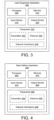
- FIG. 4 depicts one embodiment of a base station apparatus 400 that may be used for triggering HARQ-ACK feedback for a downlink slot set, according to embodiments of the disclosure.
- the base station apparatus 400 may be one embodiment of the base unit 110 and/or gNB 210, described above.
- the base station apparatus 400 may include a processor 405, a memory 410, an input device 415, an output device 420, a transceiver 425 for communicating with one or more remote units 105 and/or a mobile core network 130.
- the transceiver 425 may include a transmitter 430 and a receiver 435.
- the transceiver 425 may also support one or more network interfaces 440, such as the Uu interface, N2 interface, N3 interface, and/or other network interfaces suitable for communication with a remote unit and/or core network.
- the input device 415 and the output device 420 are combined into a single device, such as a touchscreen.
- the base station apparatus 400 may not include any input device 415 and/or output device 420.
- the processor 405, in one embodiment, may include any known controller capable of executing computer-readable instructions and/or capable of performing logical operations.
- the processor 405 may be a microcontroller, a microprocessor, a central processing unit (“CPU"), a graphics processing unit (“GPU”), an auxiliary processing unit, a field programmable gate array (“FPGA”), or similar programmable controller.
- the processor 405 executes instructions stored in the memory 410 to perform the methods and routines described herein.
- the processor 405 is communicatively coupled to the memory 410, the input device 415, the output device 420, and the transceiver 425.
- the processor 405 controls the transmitter 430 to transmit a first control signal to a remote unit (such as the UE 205), the first control signal triggering HARQ-ACK feedback for a downlink slot set.
- the downlink slot set comprises multiple downlink slots and the HARQ-ACK feedback for the downlink slot set corresponds to all downlink transmissions in the downlink slot set and is to be transmitted (by the remote unit) in one UCI.
- the processor 405 controls the receiver 435 to receive UCI from the remote unit in a slot determined by the first control signal, the UCI containing the HARQ-ACK feedback for the identified downlink slot set.
- the transmitter 430 also transmits a RRC signal causing the remote unit to enter a triggered reporting mode. While in the triggered reporting mode, the remote unit does not transmit HARQ-ACK feedback to the base station apparatus 400 until the remote unit receives a UCI transmission request.
- the first control signal transmitted to the remote unit contains a UCI transmission request.
- the first control signal is an uplink grant.
- the uplink grant may include a flag to indicate the UCI transmission request (e.g., to distinguish from an uplink grant for data transmission).
- the UCI transmission request flag is one bit in the uplink grant.
- the first control signal is an uplink grant for UCI transmission.
- the processor 405 configures the remote unit with a dedicated RNTI for signaling UCI transmission. For example, the remote unit may identify an uplink grant for data transmission using a first RNTI and identify an uplink grant for UCI transmission using the dedicated RNTI. Where the remote unit identifies the uplink grant for UCI transmission using a dedicated RNTI, the uplink grant does not need to include a flag indicating a UCI transmission request. More specifically, in such a scenario the flag for indicating a UCI transmission request becomes redundant as the remote unit detects the uplink grant for UCI transmission using the dedicated RNTI.
- the first control signal indicates one or more of: a HARQ-ACK codebook size, a timing offset for UCI transmission, a UCI transmission resource in the time domain, a UCI transmission resource in the frequency domain, a Polar coding rate for UCI encoding, and a UCI transmission format.
- the first control signal points to a carrier index which designates a scheduled carrier for the UCI transmission.
- the downlink slot set includes multiple downlink transmissions.
- the downlink slot set may include multiple PDSCH transmissions on multiple slots, multiple PDSCH transmissions on multiple mini-slots, multiple PDSCH transmissions on a mix of slots and mini-slots, and/or multiple PDSCH transmissions on multiple carriers (e.g., carrier aggregation).
- the first control signal defines the downlink slot set.
- the first control signal may indicate one or more of: a starting slot index for the downlink slot set, an ending slot index for the downlink slot set, and a number of slots of the downlink slot set.
- the processor 405 defines the downlink slot set for HARQ-ACK feedback using the indication in the first control signal.
- the downlink slot set ends at a slot where the first control signal is transmitted.
- the downlink slot set may end a specific number of slots prior to a slot where the first control signal is transmitted.
- the specific number may be fixed in the technical specification, may be configured by RRC signaling, and the like.
- the transmitter 430 transmits a RRC signal for configuring a maximum number of slots in the downlink slot set.
- the first control signal is transmitted in the last slot of the downlink slot set.
- the memory 410 in one embodiment, is a computer readable storage medium.
- the memory 410 includes volatile computer storage media.
- the memory 410 may include a RAM, including dynamic RAM (“DRAM”), synchronous dynamic RAM (“SDRAM”), and/or static RAM (“SRAM”).
- the memory 410 includes non-volatile computer storage media.
- the memory 410 may include a hard disk drive, a flash memory, or any other suitable non-volatile computer storage device.
- the memory 410 includes both volatile and non-volatile computer storage media.
- the memory 410 stores data relating to triggering HARQ-ACK feedback for a downlink slot set.
- the memory 410 may store HARQ-ACK feedback, downlink slot size and placement information, and the like.
- the memory 410 also stores program code and related data, such as an operating system or other controller algorithms operating on the remote unit 105 and one or more software applications.
- the input device 415 may include any known computer input device including a touch panel, a button, a keyboard, a stylus, a microphone, or the like.
- the input device 415 may be integrated with the output device 420, for example, as a touchscreen or similar touch-sensitive display.
- the input device 415 includes two or more different devices, such as a keyboard and a touch panel.
- the input device 415 may include a camera for capturing images or otherwise inputting visual data.
- the output device 420 may include any known electronically controllable display or display device.
- the output device 420 may be designed to output visual, audible, and/or haptic signals.
- the output device 420 includes an electronic display capable of outputting visual data to a user.
- the output device 420 may include, but is not limited to, an LCD display, an LED display, an OLED display, a projector, or similar display device capable of outputting images, text, or the like to a user.
- the output device 420 includes one or more speakers for producing sound.
- the output device 420 may produce an audible alert or notification (e.g., a beep or chime).
- the output device 420 includes one or more haptic devices for producing vibrations, motion, or other haptic feedback.
- all or portions of the output device 420 may be integrated with the input device 415.
- the input device 415 and output device 420 may form a touchscreen or similar touch-sensitive display.
- the output device 420 may be located near the input device 415.
- the transceiver 425 communicates with remote unit within a mobile communication network.
- the transceiver 425 may also communicate with a core network, such as the mobile core network 130.
- the transceiver 425 may include one or more transmitters 430 and one or more receivers 435. As discussed above, the transceiver 425 may supports one or more the network interface 440 for communicating with remote units 105 and the mobile core network 130.
- Figures 5-7 depicts various embodiments of determining the downlink slot set using the first control signal.
- Figure 5 depicts a first downlink slot set 505 with multiple slots containing PDSCHs 510.
- the first downlink slot set 505 ends prior to a slot containing the control signal 515 for triggering HARQ-ACK feedback for the first downlink slot set 505.
- the first downlink slot set 505 may also include the slot containing the control signal 515.
- control signal 515 defines the end slot of the first downlink slot set 505.
- the control signal 515 indicates the slot index of the end slot.
- the control signal 515 includes a specific uplink grant that indicates the ending slot index for the first downlink slot set 505.
- control signal 515 includes a specific uplink grant that indicates the ending slot index for the first downlink slot set 505 as well as the number of slots in the first downlink slot set 505 (e.g., a set size).
- the end slot of the first downlink slot set 505 is implicitly signaled by the slot position of the control signal 515, thus eliminating the need to include an end slot index in the control signal 515.
- the UE 205 may be configured (or the network may be predefined) to recognize the slot immediately before the slot where the control signal 515 is placed as being the end of a downlink slot set, as depicted in Figure 5 . In another embodiment, the UE 205 may recognize the slot where the control signal 515 is placed as being the end of a downlink slot set.
- the control signal 515 may indicate the set size for the first downlink slot set 505.
- the set size for the first downlink slot set 505 may be semi-statically configured via RRC signaling.
- the set size is T
- the slot location of the control signal 515 implies that the first downlink slot set 505 starts at n-T and ends at slot n.
- the UE 205 recognizes the end of a downlink slot set as a slot having an offset before the slot where the control signal 515 is placed. For example, if the offset value is x and the control signal 515 is located in slot n , then the end slot for the first downlink slot set 505 is the slot n-x.
- the slot offset may be configured by the gNB 210 via RRC signaling or may be dynamically indicated in the control signal 515. A larger offset allows the UE 205 more processing time to decode the PDSCHs 610 and prepare HARQ-ACK feedback.
- a maximum slot set size is configured by the gNB 210 via RRC signaling.
- the control signal 515 containing a specific uplink grant may be transmitted in any slot within the downlink slot set, e.g., dependent on gNB implementation.
- the specific uplink grant may be transmitted in the last slot of the downlink slot set.
- the UE 205 upon receiving the control signal 515, determines the end of the first downlink slot set 505 to be the slot where the specific uplink grant is received.
- control signal 515 triggers transmission of UCI containing HARQ-ACK feedback for the first downlink slot set 505.
- the control signal 515 includes a specific uplink grant scheduling the UCI transmission.
- the UE 205 uses information in the control signal 515 to identify the slot for transmitting the UCI.
- Figure 6 depicts a second downlink slot set 605 with multiple slots containing PDSCHs 610.
- the second downlink slot set 605 also includes the slot containing the control signal 615 for triggering HARQ-ACK feedback for the second downlink slot set 605.
- the second downlink slot set 605 may end prior to a slot containing the control signal 615.
- control signal 615 defines the starting slot of the second downlink slot set 605.
- the control signal 615 includes a specific uplink grant that indicates the starting slot index for the second downlink slot set 605.
- control signal 615 includes a specific uplink grant that indicates the starting slot index for the second downlink slot set 605 as well as the number of slots in the second downlink slot set 605 (e.g., a set size).
- the set size for the second downlink slot set 605 may be semi-statically configured via RRC signaling.
- the slot location of the control signal 615 implies that the second downlink slot set 605 starts at n-T and ends at slot n.
- control signal 615 triggers transmission of UCI containing HARQ-ACK feedback for the second downlink slot set 605.
- the control signal 615 includes a specific uplink grant scheduling the UCI transmission.
- the UE 205 uses information in the control signal 615 to identify the slot for transmitting the UCI.
- Figure 7 depicts a third downlink slot set 705 with multiple slots containing PDSCHs 710.
- the third downlink slot set 705 ends prior to a slot containing the control signal 715 for triggering HARQ-ACK feedback for the third downlink slot set 705.
- the third downlink slot set 705 may also include the slot containing the control signal 715.
- the UE 205 uses DAI values corresponding to the PDSCH 710 to identify a starting slot of the third downlink slot set 705.
- the PDSCH 710 with the DAI value of "1" in the associated PDCCH is the starting slot of the third downlink slot set 705.
- the control signal 715 indicates a set size or an ending slot index for the third downlink slot set 705.
- the slot location of the control signal 715 defines the end of the third downlink slot set 705.
- the size of the third downlink slot set 705 may be already known to the UE 205, for example via RRC signaling of the set size or maximum downlink slot set size.
- control signal 715 triggers transmission of UCI containing HARQ-ACK feedback for the third downlink slot set 705.
- the control signal 715 includes a specific uplink grant scheduling the UCI transmission.
- the UE 205 uses information in the control signal 715 to identify the slot for transmitting the UCI.
- Figure 8 is a schematic flow chart diagram illustrating one embodiment of a method 800 for triggering HARQ-ACK feedback for a downlink slot set, according to embodiments of the disclosure.
- the method 800 is performed by a remote unit, such as the remote unit 105, the UE 205, and/or the user equipment apparatus 300.
- the method 800 may be performed by a processor executing program code, for example, a microcontroller, a microprocessor, a CPU, a GPU, an auxiliary processing unit, a FPGA, or the like.
- the method 800 begins and receives 805, from a base unit, a first control signal for triggering HARQ-ACK feedback for a downlink slot set.
- the downlink slot set includes multiple downlink slots.
- the HARQ-ACK feedback for the downlink slot set corresponds to all downlink transmissions in the downlink slot set.
- the remote unit enters a triggered reporting mode in response to receiving a RRC signal from the base unit. While the remote unit is in the triggered reporting mode, HARQ-ACK feedback is only transmitted to the base unit in response to receiving a UCI transmission request.
- receiving 805 the first control signal for triggering HARQ-ACK feedback includes receiving a UCI transmission request in the first control signal.
- the first control signal is an uplink grant that includes a flag to indicate the UCI transmission request.
- the first control signal is a downlink grant that includes a flag to indicate the UCI transmission request.
- the first control signal is a group common PDCCH to trigger multiple UEs to report HARQ-ACK feedback for a downlink slot set.
- receiving 805 the first control signal for triggering HARQ-ACK feedback includes receiving an uplink grant for UCI transmission using a dedicated RNTI.
- the remote unit is configured with the dedicated RNTI used to detect an uplink grant for UCI transmission, the dedicated RNTI being separate from a RNTI used to detect an uplink grant for data transmission.
- the first control signal indicates one or more of: a HARQ-ACK codebook size, a timing offset for UCI transmission, a UCI transmission resource in the time domain, a UCI transmission resource in the frequency domain, a Polar coding rate for UCI encoding, and a UCI transmission format.
- the first control signal points to a carrier index which designates a scheduled carrier for the UCI transmission.
- the method 800 includes identifying 810 the downlink slot set in response to the first control signal.
- the first control signal indicates one or more of: a starting slot index for the downlink slot set, an ending slot index for the downlink slot set, and a number of slots of the downlink slot set.
- identifying 810 the downlink slot set includes identifying the downlink slot set for HARQ-ACK feedback using the indication.
- the downlink slot set may include multiple PDSCH transmissions on multiple slots, multiple PDSCH transmissions on multiple mini-slots, multiple PDSCH transmissions on a mix of slots and mini-slots, and/or multiple PDSCH transmissions on multiple carriers (e.g., carrier aggregation).
- the downlink slot set ends a specific number of slots prior to a slot where the first control signal is received. In other embodiments, the downlink slot set ends at a slot where the first control signal is received. In further embodiments, identifying 810 the downlink slot set includes receiving an RRC signal for configuring a maximum number of slots of the downlink slot set, wherein the first control signal is received in the last slot of the downlink slot set.
- the method 800 includes transmitting 815 UCI to the base unit in a slot determined using the first control signal.
- the UCI contains the HARQ-ACK feedback for the identified downlink slot set. Note that the HARQ-ACK feedback for all downlink transmissions in the downlink slot set is transmitted in one UCI.
- the method 800 ends.
- Figure 9 is a schematic flow chart diagram illustrating one embodiment of a method 900 for triggering HARQ-ACK feedback for a downlink slot set, according to embodiments of the disclosure.
- the method 900 is performed by a base unit, such as the base unit 110, the gNB 210, and or the base station apparatus 400.
- the method 900 may be performed by a processor executing program code, for example, a microcontroller, a microprocessor, a CPU, a GPU, an auxiliary processing unit, a FPGA, or the like.
- the method 900 begins and transmits 905, to a remote unit, a first control signal for triggering HARQ-ACK feedback for a downlink slot set.
- the downlink slot set includes multiple downlink slots.
- the HARQ-ACK feedback for the downlink slot set corresponds to all downlink transmissions in the downlink slot set.
- the remote unit is in a triggered reporting mode (e.g., the remote unit may enter the triggered reporting mode in response to receiving a RRC signal from the base unit). While the remote unit is in the triggered reporting mode, HARQ-ACK feedback is only transmitted to the base unit in response to receiving a UCI transmission request.
- transmitting 905 the first control signal for triggering HARQ-ACK feedback includes transmitting a UCI transmission request in the first control signal.
- the first control signal is an uplink grant that includes a flag to indicate the UCI transmission request.
- the first control signal is a downlink grant that includes a flag to indicate the UCI transmission request.
- the first control transmission request is triggered reporting mode
- the first control signal is a downlink grant that includes a flag to indicate the UCI transmission request.
- the first control signal is a group common PDCCH to trigger multiple UEs to report HARQ-ACK feedback for a downlink slot set.
- transmitting 905 the first control signal for triggering HARQ-ACK feedback includes transmitting an uplink grant for UCI transmission using a dedicated RNTI.
- the remote unit is configured with the dedicated RNTI used to detect an uplink grant for UCI transmission, the dedicated RNTI being separate from a RNTI used to detect an uplink grant for data transmission.
- the first control signal indicates one or more of: a HARQ-ACK codebook size, a timing offset for UCI transmission, a UCI transmission resource in the time domain, a UCI transmission resource in the frequency domain, a Polar coding rate for UCI encoding, and a UCI transmission format.
- the first control signal points to a carrier index which designates a scheduled carrier for the UCI transmission.
- the method 900 includes receiving 910 UCI from the remote unit in a slot determined using the first control signal.
- the UCI contains the HARQ-ACK feedback for the identified downlink slot set. Note that the HARQ-ACK feedback for all downlink transmissions in the downlink slot set is transmitted in one UCI.
- the method 900 ends.
- the first control signal indicates one or more of: a starting slot index for the downlink slot set, an ending slot index for the downlink slot set, and a number of slots of the downlink slot set.
- the downlink slot set may include multiple PDSCH transmissions on multiple slots, multiple PDSCH transmissions on multiple mini-slots, multiple PDSCH transmissions on a mix of slots and mini-slots, and/or multiple PDSCH transmissions on multiple carriers (e.g., carrier aggregation).
- the downlink slot set ends a specific number of slots prior to a slot where the first control signal is transmitted. In other embodiments, the downlink slot set ends at a slot where the first control signal is transmitted. In further embodiments, the remote unit may be configured (e.g., the RRC signaling) with a maximum number of slots of the downlink slot set, wherein the first control signal is transmitted in the last slot of the downlink slot set.
Landscapes
- Engineering & Computer Science (AREA)
- Computer Networks & Wireless Communication (AREA)
- Signal Processing (AREA)
- Mobile Radio Communication Systems (AREA)
Claims (16)
- Einrichtung (300), umfassend:einen Empfänger (335), der dazu konfiguriert ist, ein erstes Steuersignal (515) von einer Basiseinheit (400) zu empfangen, um hybrides automatisches Wiederholungsanforderungsbestätigungsfeedback (HARQ-ACK-Feedback) für einen Downlink-Slot-Satz (505) auszulösen, wobei der Downlink-Slot-Satz (505) mehrere Downlink-Slots (510) umfasst und das HARQ-ACK-Feedback für den Downlink-Slot-Satz (505) allen Downlink-Übertragungen im Downlink-Slot-Satz (505) entspricht und in einer Uplink-Steuerinformation (UCI) übertragen wird, und das erste Steuersignal einen Trägerindex angibt, der einen geplanten Träger für die UCI-Übertragung angibt;einen Prozessor (305), der dazu konfiguriert ist, den Downlink-Slot-Satz (505) und den geplanten Träger als Reaktion auf das erste Steuersignal (515) unter Verwendung der im ersten Steuersignal empfangenen Angabe zu identifizieren; undeinen Sender (330), der dazu konfiguriert ist, eine UCI in einem Schlitz und auf dem Träger, der durch das erste Steuersignal (515) bestimmt wird, an die Basiseinheit (400) zu übertragen, wobei die UCI das HARQ-ACK-Feedback für den identifizierten Downlink-Slot-Satz (505) umfasst.
- Einrichtung nach Anspruch 1, wobei der Empfänger (335) ferner dazu konfiguriert ist, ein Radio Resource Control-Signal (RRC-Signal) zu empfangen, und der Prozessor (305) dazu konfiguriert ist, in einen ausgelösten Berichtsmodus zu wechseln, wobei die Einrichtung (300) kein HARQ-ACK-Feedback überträgt, bis eine UCI-Übertragungsanforderung empfangen wird, wobei das erste Steuersignal (515) eine UCI-Übertragungsanforderung enthält, und wobei optional das erste Steuersignal (515) eine Uplink-Gewährung ist, die ein Flag zum Anzeigen der UCI-Übertragungsanforderung einschließt.
- Einrichtung nach Anspruch 1, wobei das erste Steuersignal (515) eine Uplink-Gewährung für eine UCI-Übertragung ist und wobei der Prozessor (305) dazu konfiguriert ist, eine Uplink-Gewährung für eine Datenübertragung unter Verwendung einer ersten temporären Funknetzkennung (RNTI) zu erkennen und die Uplink-Gewährung für eine UCI-Übertragung unter Verwendung einer zweiten RNTI zu erkennen.
- Einrichtung nach Anspruch 1, wobei der Downlink-Slot-Satz (505) eines oder mehrere der folgenden Elemente umfasst: mehrere PDSCH-Übertragungen auf mehreren Slots, mehrere PDSCH-Übertragungen auf mehreren Mini-Slots und mehrere PDSCH-Übertragungen auf mehreren Trägern.
- Einrichtung nach Anspruch 1, wobei das erste Steuersignal (515) eines oder mehrere der folgenden Elemente angibt: eine HARQ-ACK-Codebuchgröße, einen Zeitversatz für die UCI-Übertragung, eine UCI-Übertragungsressource im Zeitbereich, eine UCI-Übertragungsressource im Frequenzbereich, eine Polar-Codierrate für die UCI-Codierung und ein UCI-Übertragungsformat.
- Einrichtung nach Anspruch 1, wobei der Downlink-Slot-Satz (505) an einer bestimmten Anzahl von Slots (510) vor einem Slot (510) endet, in dem das erste Steuersignal (515) empfangen wird, oder wobei der Downlink-Slot-Satz (505) an einem Slot (510) endet, in dem das erste Steuersignal (515) empfangen wird.
- Einrichtung nach Anspruch 1, wobei der Empfänger (335) ferner dazu konfiguriert ist, ein RRC-Signal zum Konfigurieren einer maximalen Anzahl von Slots (510) des Downlink-Slot-Satzes (505) zu empfangen, wobei das erste Steuersignal (515) im letzten Slot (510) des Downlink-Slot-Satzes (505) empfangen wird.
- Verfahren, umfassend:Empfangen eines ersten Steuersignals (515) von einer Basiseinheit (400) zum Auslösen von hybridem automatischem Wiederholungsanforderungsbestätigungsfeedback (HARQ-ACK-Feedback) für einen Downlink-Slot-Satz (505), wobei der Downlink-Slot-Satz (505) mehrere Downlink-Slots (510) umfasst und das HARQ-ACK-Feedback für den Downlink-Slot-Satz (505) allen Downlink-Übertragungen in dem Downlink-Slot-Satz (505) entspricht und in einer Uplink-Steuerinformation, UCI, übertragen wird, und das erste Steuersignal einen Trägerindex angibt, der einen geplanten Träger für die UCI-Übertragung angibt;Identifizieren des Downlink-Slot-Satzes (505) und des geplanten Trägers als Reaktion auf das erste Steuersignal (515) unter Verwendung der im ersten Steuersignal empfangenen Anzeige; undSenden der UCI an die Basiseinheit (400) in einem Slot und auf dem Träger, der durch das erste Steuersignal (515) bestimmt wird, wobei die UCI das HARQ-ACK-Feedback für den identifizierten Downlink-Slot-Satz (505) umfasst.
- Einrichtung (400), umfassend:einen Sender (430), der dazu konfiguriert ist, ein erstes Steuersignal (515) an eine Remote-Einheit (300) zu senden, um hybrides automatisches Wiederholungsanforderungsbestätigungsfeedback (HARQ-ACK-Feedback) für einen Downlink-Slot-Satz (505) auszulösen, wobei der Downlink-Slot-Satz (505) mehrere Downlink-Slots (510) umfasst und das HARQ-ACK-Feedback für den Downlink-Slot-Satz (505) allen Downlink-Übertragungen im Downlink-Slot-Satz (505) entspricht und in einer Uplink-Steuerinformation (UCI) gesendet wird, wobei das erste Steuersignal einen Trägerindex angibt, der einen geplanten Träger für die UCI-Übertragung angibt; undeinen Empfänger, der dazu konfiguriert ist, die UCI von der Remote-Einheit (300) in einem Slot und auf dem Träger zu empfangen, der durch das erste Steuersignal (515) bestimmt wird, wobei die UCI das HARQ-ACK-Feedback für den Downlink-Slot-Satz (505) umfasst.
- Einrichtung nach Anspruch 9, wobei der Sender (430) ferner dazu konfiguriert ist, ein Funkressourcensteuerungssignal (RRC-Signal) an die Remote-Einheit (300) zu senden, das die Remote-Einheit (300) anweist, in einen ausgelösten Berichtsmodus einzutreten, wobei die Remote-Einheit (300) kein HARQ-ACK-Feedback sendet, bis eine UCI-Übertragungsanforderung empfangen wird, wobei das erste Steuersignal (515) eine UCI-Übertragungsanforderung enthält, und wobei optional das erste Steuersignal (515) eine Uplink-Gewährung ist, die ein Flag zum Anzeigen der UCI-Übertragungsanforderung einschließt.
- Einrichtung nach Anspruch 9, wobei das erste Steuersignal (515) eine Uplink-Gewährung für eine UCI-Übertragung ist und wobei der Sender (430) dazu konfiguriert ist, der Remote-Einheit eine Uplink-Gewährung für eine Datenübertragung unter Verwendung einer ersten temporären Funknetzwerkkennung (RNTI) zu signalisieren und der Remote-Einheit (300) die Uplink-Gewährung für eine UCI-Übertragung unter Verwendung einer zweiten RNTI zu signalisieren.
- Einrichtung nach Anspruch 9, wobei der Downlink-Slot-Satz (505) eines oder mehrere der folgenden Elemente umfasst: mehrere PDSCH-Übertragungen auf mehreren Slots (510), mehrere PDSCH-Übertragungen auf mehreren Mini-Slots und mehrere PDSCH-Übertragungen auf mehreren Trägern.
- Einrichtung nach Anspruch 9, wobei das erste Steuersignal (515) eines oder mehrere der folgenden Elemente angibt: HARQ-ACK-Codebuchgröße, Zeitversatz für UCI-Übertragung, UCI-Übertragungsressource im Zeitbereich, UCI-Übertragungsressource im Frequenzbereich, Polar-Codierrate für UCI-Codierung, UCI-Übertragungsformat.
- Einrichtung nach Anspruch 9, wobei der Downlink-Slot-Satz (505) für HARQ-ACK-Feedback eine bestimmte Anzahl von Slots vor einem Slot endet, in dem das erste Steuersignal (515) übertragen wird, oder wobei der Downlink-Slot-Satz (505) für HARQ-ACK-Feedback an einem Slot endet, in dem das erste Steuersignal (515) übertragen wird.
- Einrichtung nach Anspruch 9, wobei der Sender (430) ferner dazu konfiguriert ist, ein RRC-Signal zum Konfigurieren einer maximalen Anzahl von Slots des Downlink-Slot-Satzes (505) für HARQ-ACK-Feedback zu senden, wobei das erste Steuersignal (515) im letzten Slot des Downlink-Slot-Satzes (505) übertragen wird.
- Verfahren, umfassend:Senden eines ersten Steuersignals (515) an eine Remote-Einheit (300) zum Auslösen einer hybriden automatischen Wiederholungsanforderungsbestätigung (HARQ-ACK) für einen Downlink-Slot-Satz (505), wobei der Downlink-Slot-Satz (505) mehrere Downlink-Slots (510) umfasst und das HARQ-ACK-Feedback für den Downlink-Slot-Satz (505) allen Downlink-Übertragungen im Downlink-Slot-Satz (505) entspricht und in einer Uplink-Steuerinformation (UCI) gesendet wird, wobei das erste Steuersignal einen Trägerindex angibt, der einen geplanten Träger für die UCI-Übertragung angibt; undEmpfangen der UCI von der Remote-Einheit (300) in einem Slot und auf dem Träger, der durch das erste Steuersignal (515) bestimmt wird, wobei die UCI das HARQ-ACK-Feedback für den Downlink-Slot-Satz (505) umfasst.
Applications Claiming Priority (1)
| Application Number | Priority Date | Filing Date | Title |
|---|---|---|---|
| PCT/CN2017/097134 WO2019028844A1 (en) | 2017-08-11 | 2017-08-11 | HARQ-ACK FEEDBACK RELEASE FOR DOWNLINK CREAM SET |
Publications (4)
| Publication Number | Publication Date |
|---|---|
| EP3665993A1 EP3665993A1 (de) | 2020-06-17 |
| EP3665993A4 EP3665993A4 (de) | 2021-03-03 |
| EP3665993B1 true EP3665993B1 (de) | 2024-07-31 |
| EP3665993C0 EP3665993C0 (de) | 2024-07-31 |
Family
ID=65272797
Family Applications (1)
| Application Number | Title | Priority Date | Filing Date |
|---|---|---|---|
| EP17920831.9A Active EP3665993B1 (de) | 2017-08-11 | 2017-08-11 | Auslösung von harq-ack-rückkopplung für einen downlink-schlitzsatz |
Country Status (4)
| Country | Link |
|---|---|
| US (2) | US11239953B2 (de) |
| EP (1) | EP3665993B1 (de) |
| CN (2) | CN111226475B (de) |
| WO (1) | WO2019028844A1 (de) |
Families Citing this family (17)
| Publication number | Priority date | Publication date | Assignee | Title |
|---|---|---|---|---|
| WO2018093180A1 (ko) * | 2016-11-16 | 2018-05-24 | 주식회사 케이티 | 차세대 무선 네트워크에서 상향링크 제어정보를 송수신하는 방법 및 그 장치 |
| WO2019061277A1 (en) * | 2017-09-29 | 2019-04-04 | Lenovo (Beijing) Limited | FEEDBACK MESSAGE HAVING A SEQUENCE INDICATING FEEDBACK INFORMATION CORRESPONDING TO DATA BLOCKS |
| KR102381374B1 (ko) * | 2017-11-17 | 2022-04-01 | 삼성전자주식회사 | 무선 통신 시스템에서 제어 정보 송수신 방법 및 장치 |
| WO2019098761A1 (ko) | 2017-11-17 | 2019-05-23 | 삼성전자 주식회사 | 무선 통신 시스템에서 제어 정보 송수신 방법 및 장치 |
| WO2019157639A1 (zh) * | 2018-02-13 | 2019-08-22 | Oppo广东移动通信有限公司 | 一种harq信息的传输方法及装置、计算机存储介质 |
| CN110324117B (zh) | 2018-03-30 | 2021-10-26 | 大唐移动通信设备有限公司 | 一种数据传输方法、终端设备及网络设备 |
| KR102600387B1 (ko) * | 2018-05-10 | 2023-11-09 | 삼성전자 주식회사 | 차세대 이동 통신 시스템에서 주변 셀의 기준 신호로 준지속적 사운딩 기준 신호를 지시하는 방법 및 장치 |
| CN110557231B (zh) * | 2018-06-04 | 2021-02-12 | 华为技术有限公司 | 传输信息的方法和通信设备 |
| US12120060B2 (en) * | 2018-09-19 | 2024-10-15 | Qualcomm Incorporated | Acknowledgement codebook design for multiple transmission reception points |
| CN111435899B (zh) | 2019-02-15 | 2021-08-24 | 维沃移动通信有限公司 | 混合自动重传请求harq反馈方法、终端及网络设备 |
| CN112789924A (zh) | 2019-04-30 | 2021-05-11 | Oppo广东移动通信有限公司 | 一种资源确定方法、设备及存储介质 |
| CN113079709B (zh) * | 2019-11-06 | 2023-04-18 | 北京小米移动软件有限公司 | Harq-ack处理方法及装置、通信设备及存储介质 |
| US11558152B2 (en) * | 2019-11-18 | 2023-01-17 | Qualcomm Incorporated | Transmission of uplink control information (UCI) based on one or more codebooks |
| WO2021114051A1 (zh) * | 2019-12-09 | 2021-06-17 | 北京小米移动软件有限公司 | 反馈方法、反馈装置及存储介质 |
| KR20220139303A (ko) * | 2020-02-14 | 2022-10-14 | 지티이 코포레이션 | 피드백 정보 전송을 위한 방법 및 디바이스 |
| WO2022011674A1 (en) * | 2020-07-17 | 2022-01-20 | Nec Corporation | Method, device and computer storage medium for communication |
| US12309797B2 (en) | 2021-04-05 | 2025-05-20 | Ofinno, Llc | Requesting feedback information in multi-downlink scheduling |
Family Cites Families (16)
| Publication number | Priority date | Publication date | Assignee | Title |
|---|---|---|---|---|
| CN101800620A (zh) * | 2009-12-25 | 2010-08-11 | 中兴通讯股份有限公司 | 一种发送物理上行控制信道的方法及装置 |
| US9301183B2 (en) * | 2012-09-28 | 2016-03-29 | Intel Corporation | Transmission of uplink control information in inter-eNB carrier aggregation |
| SG11201606245RA (en) * | 2014-01-29 | 2016-08-30 | Interdigital Patent Holdings | Uplink transmissions in wireless communications |
| CN105515733B (zh) * | 2014-09-24 | 2019-03-12 | 中兴通讯股份有限公司 | 一种反馈方法及装置 |
| TWI626840B (zh) * | 2015-01-09 | 2018-06-11 | 宏達國際電子股份有限公司 | 通訊系統之無線通訊處理方法 |
| WO2016161629A1 (en) | 2015-04-10 | 2016-10-13 | Mediatek Singapore Pte. Ltd. | Methods and apparatus for pucch resource allocation of mtc |
| CN107925523B (zh) * | 2015-09-11 | 2021-04-13 | 苹果公司 | 无线系统中的上行链路控制信息的传输 |
| EP3654562A1 (de) * | 2015-11-05 | 2020-05-20 | NTT DoCoMo, Inc. | Benutzerendgerät, funkbasisstation und funkkommunikationsverfahren |
| EP3413670A4 (de) * | 2016-02-02 | 2019-10-16 | LG Electronics Inc. -1- | Verfahren und vorrichtung zum senden/empfangen eines drahtlossignals in einem drahtloskommunikationssystem |
| CN107332646B (zh) * | 2016-04-29 | 2021-05-11 | 中兴通讯股份有限公司 | Harq-ack的发送方法及装置 |
| US11171746B2 (en) * | 2016-06-15 | 2021-11-09 | Apple Inc. | Channel state and beam related information reporting |
| KR102355797B1 (ko) * | 2016-08-09 | 2022-01-26 | 삼성전자 주식회사 | 무선 셀룰라 통신 시스템에서 채널 전송 방법 및 장치 |
| CN106953718A (zh) * | 2017-03-24 | 2017-07-14 | 宇龙计算机通信科技(深圳)有限公司 | 一种码块的重传进程的实现方法、装置及设备 |
| CN109391440B (zh) * | 2017-08-11 | 2020-12-15 | 华为技术有限公司 | 一种混合自动重传请求harq反馈方法及设备 |
| US11539479B2 (en) * | 2017-08-11 | 2022-12-27 | Lenovo (Beijing) Limited | HARQ-ACK for a plurality of carrier groups of a downlink slot set |
| WO2019028857A1 (en) * | 2017-08-11 | 2019-02-14 | Lenovo (Beijing) Limited | HARQ-ACK FEEDBACK SYNCHRONIZATION FOR SPS-PDSCH |
-
2017
- 2017-08-11 CN CN201780093798.0A patent/CN111226475B/zh active Active
- 2017-08-11 WO PCT/CN2017/097134 patent/WO2019028844A1/en not_active Ceased
- 2017-08-11 EP EP17920831.9A patent/EP3665993B1/de active Active
- 2017-08-11 CN CN202410379195.9A patent/CN118264371A/zh active Pending
- 2017-08-11 US US16/638,404 patent/US11239953B2/en active Active
-
2022
- 2022-01-28 US US17/587,329 patent/US11838128B2/en active Active
Also Published As
| Publication number | Publication date |
|---|---|
| CN118264371A (zh) | 2024-06-28 |
| US11838128B2 (en) | 2023-12-05 |
| EP3665993A4 (de) | 2021-03-03 |
| US20220158767A1 (en) | 2022-05-19 |
| US11239953B2 (en) | 2022-02-01 |
| EP3665993C0 (de) | 2024-07-31 |
| CN111226475A (zh) | 2020-06-02 |
| CN111226475B (zh) | 2024-04-19 |
| US20200366417A1 (en) | 2020-11-19 |
| EP3665993A1 (de) | 2020-06-17 |
| WO2019028844A1 (en) | 2019-02-14 |
Similar Documents
| Publication | Publication Date | Title |
|---|---|---|
| US11838128B2 (en) | Triggering HARQ-ACK feedback for a downlink slot set | |
| US20250219769A1 (en) | Harq-ack feedback timing for sps pdsch | |
| US12015487B2 (en) | Ceasing transmission repetitions | |
| US11153853B2 (en) | Sidelink control information indication | |
| US11539479B2 (en) | HARQ-ACK for a plurality of carrier groups of a downlink slot set | |
| CN110214463B (zh) | 通信配置选择 | |
| US11991702B2 (en) | Resource reservation | |
| CN108463963B (zh) | 用于无线通信系统中的数据确认的设备及其方法 | |
| WO2018170916A1 (en) | Pucch format indication and resource allocation | |
| EP4080980B1 (de) | Anzeige von planungsanfragen | |
| US11146346B2 (en) | Transmitting a message in response to receiving a message | |
| WO2018227591A1 (en) | Information indicating data in slots | |
| US11658774B2 (en) | Determining a resource field that carries feedback information | |
| CN117880982A (zh) | 免许可资源分配 | |
| KR102535001B1 (ko) | 접속 상태로의 전환 결정 |
Legal Events
| Date | Code | Title | Description |
|---|---|---|---|
| STAA | Information on the status of an ep patent application or granted ep patent |
Free format text: STATUS: THE INTERNATIONAL PUBLICATION HAS BEEN MADE |
|
| PUAI | Public reference made under article 153(3) epc to a published international application that has entered the european phase |
Free format text: ORIGINAL CODE: 0009012 |
|
| STAA | Information on the status of an ep patent application or granted ep patent |
Free format text: STATUS: REQUEST FOR EXAMINATION WAS MADE |
|
| 17P | Request for examination filed |
Effective date: 20200311 |
|
| AK | Designated contracting states |
Kind code of ref document: A1 Designated state(s): AL AT BE BG CH CY CZ DE DK EE ES FI FR GB GR HR HU IE IS IT LI LT LU LV MC MK MT NL NO PL PT RO RS SE SI SK SM TR |
|
| AX | Request for extension of the european patent |
Extension state: BA ME |
|
| DAV | Request for validation of the european patent (deleted) | ||
| DAX | Request for extension of the european patent (deleted) | ||
| A4 | Supplementary search report drawn up and despatched |
Effective date: 20210203 |
|
| RIC1 | Information provided on ipc code assigned before grant |
Ipc: H04W 72/04 20090101AFI20210128BHEP Ipc: H04L 1/18 20060101ALI20210128BHEP Ipc: H04L 1/16 20060101ALI20210128BHEP |
|
| STAA | Information on the status of an ep patent application or granted ep patent |
Free format text: STATUS: EXAMINATION IS IN PROGRESS |
|
| 17Q | First examination report despatched |
Effective date: 20221123 |
|
| REG | Reference to a national code |
Free format text: PREVIOUS MAIN CLASS: H04W0072040000 Ipc: H04L0001160700 Ref country code: DE Ref legal event code: R079 Ref document number: 602017083787 Country of ref document: DE |
|
| GRAP | Despatch of communication of intention to grant a patent |
Free format text: ORIGINAL CODE: EPIDOSNIGR1 |
|
| STAA | Information on the status of an ep patent application or granted ep patent |
Free format text: STATUS: GRANT OF PATENT IS INTENDED |
|
| RIC1 | Information provided on ipc code assigned before grant |
Ipc: H04L 1/1867 20230101ALN20240313BHEP Ipc: H04L 1/1829 20230101ALI20240313BHEP Ipc: H04L 1/1607 20230101AFI20240313BHEP |
|
| INTG | Intention to grant announced |
Effective date: 20240403 |
|
| GRAS | Grant fee paid |
Free format text: ORIGINAL CODE: EPIDOSNIGR3 |
|
| GRAA | (expected) grant |
Free format text: ORIGINAL CODE: 0009210 |
|
| STAA | Information on the status of an ep patent application or granted ep patent |
Free format text: STATUS: THE PATENT HAS BEEN GRANTED |
|
| AK | Designated contracting states |
Kind code of ref document: B1 Designated state(s): AL AT BE BG CH CY CZ DE DK EE ES FI FR GB GR HR HU IE IS IT LI LT LU LV MC MK MT NL NO PL PT RO RS SE SI SK SM TR |
|
| REG | Reference to a national code |
Ref country code: CH Ref legal event code: EP Ref country code: GB Ref legal event code: FG4D |
|
| REG | Reference to a national code |
Ref country code: DE Ref legal event code: R096 Ref document number: 602017083787 Country of ref document: DE |
|
| REG | Reference to a national code |
Ref country code: IE Ref legal event code: FG4D |
|
| U01 | Request for unitary effect filed |
Effective date: 20240819 |
|
| U07 | Unitary effect registered |
Designated state(s): AT BE BG DE DK EE FI FR IT LT LU LV MT NL PT SE SI Effective date: 20240828 |
|
| U20 | Renewal fee for the european patent with unitary effect paid |
Year of fee payment: 8 Effective date: 20241025 |
|
| PG25 | Lapsed in a contracting state [announced via postgrant information from national office to epo] |
Ref country code: NO Free format text: LAPSE BECAUSE OF FAILURE TO SUBMIT A TRANSLATION OF THE DESCRIPTION OR TO PAY THE FEE WITHIN THE PRESCRIBED TIME-LIMIT Effective date: 20241031 |
|
| PG25 | Lapsed in a contracting state [announced via postgrant information from national office to epo] |
Ref country code: GR Free format text: LAPSE BECAUSE OF FAILURE TO SUBMIT A TRANSLATION OF THE DESCRIPTION OR TO PAY THE FEE WITHIN THE PRESCRIBED TIME-LIMIT Effective date: 20241101 Ref country code: PL Free format text: LAPSE BECAUSE OF FAILURE TO SUBMIT A TRANSLATION OF THE DESCRIPTION OR TO PAY THE FEE WITHIN THE PRESCRIBED TIME-LIMIT Effective date: 20240731 |
|
| PG25 | Lapsed in a contracting state [announced via postgrant information from national office to epo] |
Ref country code: IS Free format text: LAPSE BECAUSE OF FAILURE TO SUBMIT A TRANSLATION OF THE DESCRIPTION OR TO PAY THE FEE WITHIN THE PRESCRIBED TIME-LIMIT Effective date: 20241130 |
|
| PG25 | Lapsed in a contracting state [announced via postgrant information from national office to epo] |
Ref country code: HR Free format text: LAPSE BECAUSE OF FAILURE TO SUBMIT A TRANSLATION OF THE DESCRIPTION OR TO PAY THE FEE WITHIN THE PRESCRIBED TIME-LIMIT Effective date: 20240731 |
|
| PG25 | Lapsed in a contracting state [announced via postgrant information from national office to epo] |
Ref country code: ES Free format text: LAPSE BECAUSE OF FAILURE TO SUBMIT A TRANSLATION OF THE DESCRIPTION OR TO PAY THE FEE WITHIN THE PRESCRIBED TIME-LIMIT Effective date: 20240731 Ref country code: RS Free format text: LAPSE BECAUSE OF FAILURE TO SUBMIT A TRANSLATION OF THE DESCRIPTION OR TO PAY THE FEE WITHIN THE PRESCRIBED TIME-LIMIT Effective date: 20241031 |
|
| PG25 | Lapsed in a contracting state [announced via postgrant information from national office to epo] |
Ref country code: RS Free format text: LAPSE BECAUSE OF FAILURE TO SUBMIT A TRANSLATION OF THE DESCRIPTION OR TO PAY THE FEE WITHIN THE PRESCRIBED TIME-LIMIT Effective date: 20241031 Ref country code: PL Free format text: LAPSE BECAUSE OF FAILURE TO SUBMIT A TRANSLATION OF THE DESCRIPTION OR TO PAY THE FEE WITHIN THE PRESCRIBED TIME-LIMIT Effective date: 20240731 Ref country code: NO Free format text: LAPSE BECAUSE OF FAILURE TO SUBMIT A TRANSLATION OF THE DESCRIPTION OR TO PAY THE FEE WITHIN THE PRESCRIBED TIME-LIMIT Effective date: 20241031 Ref country code: IS Free format text: LAPSE BECAUSE OF FAILURE TO SUBMIT A TRANSLATION OF THE DESCRIPTION OR TO PAY THE FEE WITHIN THE PRESCRIBED TIME-LIMIT Effective date: 20241130 Ref country code: HR Free format text: LAPSE BECAUSE OF FAILURE TO SUBMIT A TRANSLATION OF THE DESCRIPTION OR TO PAY THE FEE WITHIN THE PRESCRIBED TIME-LIMIT Effective date: 20240731 Ref country code: GR Free format text: LAPSE BECAUSE OF FAILURE TO SUBMIT A TRANSLATION OF THE DESCRIPTION OR TO PAY THE FEE WITHIN THE PRESCRIBED TIME-LIMIT Effective date: 20241101 Ref country code: ES Free format text: LAPSE BECAUSE OF FAILURE TO SUBMIT A TRANSLATION OF THE DESCRIPTION OR TO PAY THE FEE WITHIN THE PRESCRIBED TIME-LIMIT Effective date: 20240731 |
|
| REG | Reference to a national code |
Ref country code: CH Ref legal event code: PL |
|
| PG25 | Lapsed in a contracting state [announced via postgrant information from national office to epo] |
Ref country code: SM Free format text: LAPSE BECAUSE OF FAILURE TO SUBMIT A TRANSLATION OF THE DESCRIPTION OR TO PAY THE FEE WITHIN THE PRESCRIBED TIME-LIMIT Effective date: 20240731 |
|
| PG25 | Lapsed in a contracting state [announced via postgrant information from national office to epo] |
Ref country code: CH Free format text: LAPSE BECAUSE OF NON-PAYMENT OF DUE FEES Effective date: 20240831 Ref country code: MC Free format text: LAPSE BECAUSE OF FAILURE TO SUBMIT A TRANSLATION OF THE DESCRIPTION OR TO PAY THE FEE WITHIN THE PRESCRIBED TIME-LIMIT Effective date: 20240731 |
|
| PG25 | Lapsed in a contracting state [announced via postgrant information from national office to epo] |
Ref country code: CZ Free format text: LAPSE BECAUSE OF FAILURE TO SUBMIT A TRANSLATION OF THE DESCRIPTION OR TO PAY THE FEE WITHIN THE PRESCRIBED TIME-LIMIT Effective date: 20240731 |
|
| PG25 | Lapsed in a contracting state [announced via postgrant information from national office to epo] |
Ref country code: SK Free format text: LAPSE BECAUSE OF FAILURE TO SUBMIT A TRANSLATION OF THE DESCRIPTION OR TO PAY THE FEE WITHIN THE PRESCRIBED TIME-LIMIT Effective date: 20240731 |
|
| PLBE | No opposition filed within time limit |
Free format text: ORIGINAL CODE: 0009261 |
|
| STAA | Information on the status of an ep patent application or granted ep patent |
Free format text: STATUS: NO OPPOSITION FILED WITHIN TIME LIMIT |
|
| 26N | No opposition filed |
Effective date: 20250501 |
|
| PG25 | Lapsed in a contracting state [announced via postgrant information from national office to epo] |
Ref country code: IE Free format text: LAPSE BECAUSE OF NON-PAYMENT OF DUE FEES Effective date: 20240811 |
|
| U20 | Renewal fee for the european patent with unitary effect paid |
Year of fee payment: 9 Effective date: 20250825 |
|
| PGFP | Annual fee paid to national office [announced via postgrant information from national office to epo] |
Ref country code: GB Payment date: 20250826 Year of fee payment: 9 |
|
| PG25 | Lapsed in a contracting state [announced via postgrant information from national office to epo] |
Ref country code: RO Free format text: LAPSE BECAUSE OF FAILURE TO SUBMIT A TRANSLATION OF THE DESCRIPTION OR TO PAY THE FEE WITHIN THE PRESCRIBED TIME-LIMIT Effective date: 20240731 |
|
| PG25 | Lapsed in a contracting state [announced via postgrant information from national office to epo] |
Ref country code: CY Free format text: LAPSE BECAUSE OF FAILURE TO SUBMIT A TRANSLATION OF THE DESCRIPTION OR TO PAY THE FEE WITHIN THE PRESCRIBED TIME-LIMIT; INVALID AB INITIO Effective date: 20170811 |