EP3665738B1 - Low-polarization lithium oxygen battery - Google Patents
Low-polarization lithium oxygen battery Download PDFInfo
- Publication number
- EP3665738B1 EP3665738B1 EP17752371.9A EP17752371A EP3665738B1 EP 3665738 B1 EP3665738 B1 EP 3665738B1 EP 17752371 A EP17752371 A EP 17752371A EP 3665738 B1 EP3665738 B1 EP 3665738B1
- Authority
- EP
- European Patent Office
- Prior art keywords
- lithium
- air
- carbon
- diffusion layer
- electrolyte
- Prior art date
- Legal status (The legal status is an assumption and is not a legal conclusion. Google has not performed a legal analysis and makes no representation as to the accuracy of the status listed.)
- Active
Links
- QTJOIXXDCCFVFV-UHFFFAOYSA-N [Li].[O] Chemical compound [Li].[O] QTJOIXXDCCFVFV-UHFFFAOYSA-N 0.000 title description 7
- 239000003792 electrolyte Substances 0.000 claims description 51
- OKTJSMMVPCPJKN-UHFFFAOYSA-N Carbon Chemical compound [C] OKTJSMMVPCPJKN-UHFFFAOYSA-N 0.000 claims description 43
- 229910052799 carbon Inorganic materials 0.000 claims description 40
- 239000007789 gas Substances 0.000 claims description 26
- 239000002245 particle Substances 0.000 claims description 26
- 238000009792 diffusion process Methods 0.000 claims description 23
- 238000000034 method Methods 0.000 claims description 22
- 239000002608 ionic liquid Substances 0.000 claims description 17
- 239000000463 material Substances 0.000 claims description 15
- 229910016329 MxZn1-xO Inorganic materials 0.000 claims description 13
- 229910052742 iron Inorganic materials 0.000 claims description 12
- 229910052723 transition metal Inorganic materials 0.000 claims description 12
- 150000003624 transition metals Chemical class 0.000 claims description 12
- 239000006229 carbon black Substances 0.000 claims description 9
- 239000004020 conductor Substances 0.000 claims description 9
- 239000011244 liquid electrolyte Substances 0.000 claims description 7
- 239000007787 solid Substances 0.000 claims description 7
- 229910052802 copper Inorganic materials 0.000 claims description 6
- VNWKTOKETHGBQD-UHFFFAOYSA-N methane Chemical compound C VNWKTOKETHGBQD-UHFFFAOYSA-N 0.000 claims description 6
- 229910003002 lithium salt Inorganic materials 0.000 claims description 5
- 159000000002 lithium salts Chemical class 0.000 claims description 5
- QSZMZKBZAYQGRS-UHFFFAOYSA-N lithium;bis(trifluoromethylsulfonyl)azanide Chemical compound [Li+].FC(F)(F)S(=O)(=O)[N-]S(=O)(=O)C(F)(F)F QSZMZKBZAYQGRS-UHFFFAOYSA-N 0.000 claims description 5
- 229910052748 manganese Inorganic materials 0.000 claims description 5
- 238000004519 manufacturing process Methods 0.000 claims description 5
- 229910052759 nickel Inorganic materials 0.000 claims description 5
- 239000003570 air Substances 0.000 claims description 4
- 239000003365 glass fiber Substances 0.000 claims description 4
- 230000002209 hydrophobic effect Effects 0.000 claims description 4
- IJGRMHOSHXDMSA-UHFFFAOYSA-N nitrogen Substances N#N IJGRMHOSHXDMSA-UHFFFAOYSA-N 0.000 claims description 4
- 229910052757 nitrogen Inorganic materials 0.000 claims description 4
- WUFQNPMBKMKEHN-UHFFFAOYSA-N bis(trifluoromethylsulfonyl)azanide;diethyl-(2-methoxyethyl)-methylazanium Chemical compound CC[N+](C)(CC)CCOC.FC(F)(F)S(=O)(=O)[N-]S(=O)(=O)C(F)(F)F WUFQNPMBKMKEHN-UHFFFAOYSA-N 0.000 claims description 3
- 229920000620 organic polymer Polymers 0.000 claims description 3
- 229920000049 Carbon (fiber) Polymers 0.000 claims description 2
- 229920003043 Cellulose fiber Polymers 0.000 claims description 2
- 239000004917 carbon fiber Substances 0.000 claims description 2
- BXHHZLMBMOBPEH-UHFFFAOYSA-N diethyl-(2-methoxyethyl)-methylazanium Chemical compound CC[N+](C)(CC)CCOC BXHHZLMBMOBPEH-UHFFFAOYSA-N 0.000 claims description 2
- 238000005538 encapsulation Methods 0.000 claims description 2
- 239000004744 fabric Substances 0.000 claims description 2
- 239000011261 inert gas Substances 0.000 claims description 2
- 238000001179 sorption measurement Methods 0.000 claims description 2
- 125000001889 triflyl group Chemical group FC(F)(F)S(*)(=O)=O 0.000 claims 1
- 210000004027 cell Anatomy 0.000 description 40
- 229910003473 lithium bis(trifluoromethanesulfonyl)imide Inorganic materials 0.000 description 28
- 229910052744 lithium Inorganic materials 0.000 description 26
- XEEYBQQBJWHFJM-UHFFFAOYSA-N Iron Chemical compound [Fe] XEEYBQQBJWHFJM-UHFFFAOYSA-N 0.000 description 18
- 229910001416 lithium ion Inorganic materials 0.000 description 17
- XLOMVQKBTHCTTD-UHFFFAOYSA-N Zinc monoxide Chemical compound [Zn]=O XLOMVQKBTHCTTD-UHFFFAOYSA-N 0.000 description 16
- WHXSMMKQMYFTQS-UHFFFAOYSA-N Lithium Chemical compound [Li] WHXSMMKQMYFTQS-UHFFFAOYSA-N 0.000 description 15
- 230000001965 increasing effect Effects 0.000 description 15
- HPGPEWYJWRWDTP-UHFFFAOYSA-N lithium peroxide Chemical compound [Li+].[Li+].[O-][O-] HPGPEWYJWRWDTP-UHFFFAOYSA-N 0.000 description 15
- 230000008569 process Effects 0.000 description 15
- HBBGRARXTFLTSG-UHFFFAOYSA-N Lithium ion Chemical compound [Li+] HBBGRARXTFLTSG-UHFFFAOYSA-N 0.000 description 12
- QVGXLLKOCUKJST-UHFFFAOYSA-N atomic oxygen Chemical compound [O] QVGXLLKOCUKJST-UHFFFAOYSA-N 0.000 description 12
- 230000001351 cycling effect Effects 0.000 description 12
- 239000001301 oxygen Substances 0.000 description 12
- 229910052760 oxygen Inorganic materials 0.000 description 12
- 239000011701 zinc Substances 0.000 description 9
- 239000011149 active material Substances 0.000 description 8
- -1 ammonium ions Chemical class 0.000 description 8
- 238000010438 heat treatment Methods 0.000 description 8
- 230000002441 reversible effect Effects 0.000 description 8
- 239000011787 zinc oxide Substances 0.000 description 8
- 230000015572 biosynthetic process Effects 0.000 description 7
- 238000006243 chemical reaction Methods 0.000 description 7
- 230000007423 decrease Effects 0.000 description 7
- 238000001878 scanning electron micrograph Methods 0.000 description 7
- 238000000151 deposition Methods 0.000 description 6
- 230000008021 deposition Effects 0.000 description 6
- 238000005259 measurement Methods 0.000 description 6
- 238000012360 testing method Methods 0.000 description 6
- 229910016914 Fe0.1Zn0.9O Inorganic materials 0.000 description 5
- 239000002033 PVDF binder Substances 0.000 description 5
- 239000011248 coating agent Substances 0.000 description 5
- 238000000576 coating method Methods 0.000 description 5
- 239000000203 mixture Substances 0.000 description 5
- 229920002981 polyvinylidene fluoride Polymers 0.000 description 5
- 238000006722 reduction reaction Methods 0.000 description 5
- OUUQCZGPVNCOIJ-UHFFFAOYSA-M Superoxide Chemical compound [O-][O] OUUQCZGPVNCOIJ-UHFFFAOYSA-M 0.000 description 4
- WYURNTSHIVDZCO-UHFFFAOYSA-N Tetrahydrofuran Chemical compound C1CCOC1 WYURNTSHIVDZCO-UHFFFAOYSA-N 0.000 description 4
- 239000010949 copper Substances 0.000 description 4
- 230000003247 decreasing effect Effects 0.000 description 4
- 238000005137 deposition process Methods 0.000 description 4
- 238000004090 dissolution Methods 0.000 description 4
- 230000034964 establishment of cell polarity Effects 0.000 description 4
- 238000011066 ex-situ storage Methods 0.000 description 4
- 230000006872 improvement Effects 0.000 description 4
- 230000010287 polarization Effects 0.000 description 4
- XLYOFNOQVPJJNP-UHFFFAOYSA-N water Substances O XLYOFNOQVPJJNP-UHFFFAOYSA-N 0.000 description 4
- XEKOWRVHYACXOJ-UHFFFAOYSA-N Ethyl acetate Chemical compound CCOC(C)=O XEKOWRVHYACXOJ-UHFFFAOYSA-N 0.000 description 3
- XOJVVFBFDXDTEG-UHFFFAOYSA-N Norphytane Natural products CC(C)CCCC(C)CCCC(C)CCCC(C)C XOJVVFBFDXDTEG-UHFFFAOYSA-N 0.000 description 3
- 238000002441 X-ray diffraction Methods 0.000 description 3
- HCHKCACWOHOZIP-UHFFFAOYSA-N Zinc Chemical compound [Zn] HCHKCACWOHOZIP-UHFFFAOYSA-N 0.000 description 3
- 239000000956 alloy Substances 0.000 description 3
- 229910003481 amorphous carbon Inorganic materials 0.000 description 3
- 239000010405 anode material Substances 0.000 description 3
- 239000011230 binding agent Substances 0.000 description 3
- 238000012512 characterization method Methods 0.000 description 3
- 229920001577 copolymer Polymers 0.000 description 3
- 238000000354 decomposition reaction Methods 0.000 description 3
- XUCJHNOBJLKZNU-UHFFFAOYSA-M dilithium;hydroxide Chemical compound [Li+].[Li+].[OH-] XUCJHNOBJLKZNU-UHFFFAOYSA-M 0.000 description 3
- 238000002848 electrochemical method Methods 0.000 description 3
- 239000011888 foil Substances 0.000 description 3
- 230000016507 interphase Effects 0.000 description 3
- 150000002500 ions Chemical class 0.000 description 3
- 230000002427 irreversible effect Effects 0.000 description 3
- 230000000670 limiting effect Effects 0.000 description 3
- 238000011068 loading method Methods 0.000 description 3
- 239000002105 nanoparticle Substances 0.000 description 3
- 238000007254 oxidation reaction Methods 0.000 description 3
- 230000037361 pathway Effects 0.000 description 3
- 230000009467 reduction Effects 0.000 description 3
- 230000002829 reductive effect Effects 0.000 description 3
- 238000003860 storage Methods 0.000 description 3
- 239000000126 substance Substances 0.000 description 3
- 230000007704 transition Effects 0.000 description 3
- 229910052725 zinc Inorganic materials 0.000 description 3
- XKRFYHLGVUSROY-UHFFFAOYSA-N Argon Chemical compound [Ar] XKRFYHLGVUSROY-UHFFFAOYSA-N 0.000 description 2
- 229920002134 Carboxymethyl cellulose Polymers 0.000 description 2
- RYGMFSIKBFXOCR-UHFFFAOYSA-N Copper Chemical compound [Cu] RYGMFSIKBFXOCR-UHFFFAOYSA-N 0.000 description 2
- 229910000733 Li alloy Inorganic materials 0.000 description 2
- FUJCRWPEOMXPAD-UHFFFAOYSA-N Li2O Inorganic materials [Li+].[Li+].[O-2] FUJCRWPEOMXPAD-UHFFFAOYSA-N 0.000 description 2
- 229920003171 Poly (ethylene oxide) Polymers 0.000 description 2
- 229920006373 Solef Polymers 0.000 description 2
- 239000000654 additive Substances 0.000 description 2
- 229910045601 alloy Inorganic materials 0.000 description 2
- 229910052782 aluminium Inorganic materials 0.000 description 2
- XAGFODPZIPBFFR-UHFFFAOYSA-N aluminium Chemical compound [Al] XAGFODPZIPBFFR-UHFFFAOYSA-N 0.000 description 2
- 238000004458 analytical method Methods 0.000 description 2
- 150000001450 anions Chemical class 0.000 description 2
- 239000003738 black carbon Substances 0.000 description 2
- 238000005266 casting Methods 0.000 description 2
- 229910017052 cobalt Inorganic materials 0.000 description 2
- 239000010941 cobalt Substances 0.000 description 2
- GUTLYIVDDKVIGB-UHFFFAOYSA-N cobalt atom Chemical compound [Co] GUTLYIVDDKVIGB-UHFFFAOYSA-N 0.000 description 2
- 238000001816 cooling Methods 0.000 description 2
- 238000001035 drying Methods 0.000 description 2
- 230000000694 effects Effects 0.000 description 2
- 238000000840 electrochemical analysis Methods 0.000 description 2
- 238000003487 electrochemical reaction Methods 0.000 description 2
- 238000000157 electrochemical-induced impedance spectroscopy Methods 0.000 description 2
- 238000005516 engineering process Methods 0.000 description 2
- 229910010272 inorganic material Inorganic materials 0.000 description 2
- 238000004502 linear sweep voltammetry Methods 0.000 description 2
- 239000007788 liquid Substances 0.000 description 2
- 230000000877 morphologic effect Effects 0.000 description 2
- 230000003647 oxidation Effects 0.000 description 2
- 238000007747 plating Methods 0.000 description 2
- 238000002360 preparation method Methods 0.000 description 2
- 238000000240 pulsed field-gradient spin echo nuclear magnetic resonance spectroscopy Methods 0.000 description 2
- 239000013557 residual solvent Substances 0.000 description 2
- 238000007086 side reaction Methods 0.000 description 2
- 239000002002 slurry Substances 0.000 description 2
- 239000000243 solution Substances 0.000 description 2
- 241000894007 species Species 0.000 description 2
- 229920003048 styrene butadiene rubber Polymers 0.000 description 2
- YLQBMQCUIZJEEH-UHFFFAOYSA-N tetrahydrofuran Natural products C=1C=COC=1 YLQBMQCUIZJEEH-UHFFFAOYSA-N 0.000 description 2
- ZXMGHDIOOHOAAE-UHFFFAOYSA-N 1,1,1-trifluoro-n-(trifluoromethylsulfonyl)methanesulfonamide Chemical compound FC(F)(F)S(=O)(=O)NS(=O)(=O)C(F)(F)F ZXMGHDIOOHOAAE-UHFFFAOYSA-N 0.000 description 1
- YZUPZGFPHUVJKC-UHFFFAOYSA-N 1-bromo-2-methoxyethane Chemical compound COCCBr YZUPZGFPHUVJKC-UHFFFAOYSA-N 0.000 description 1
- CPELXLSAUQHCOX-UHFFFAOYSA-M Bromide Chemical compound [Br-] CPELXLSAUQHCOX-UHFFFAOYSA-M 0.000 description 1
- BVKZGUZCCUSVTD-UHFFFAOYSA-L Carbonate Chemical compound [O-]C([O-])=O BVKZGUZCCUSVTD-UHFFFAOYSA-L 0.000 description 1
- 229910021112 Co0.12Zn0.88O Inorganic materials 0.000 description 1
- 229910021155 Co0.1Zn0.9O Inorganic materials 0.000 description 1
- MYMOFIZGZYHOMD-UHFFFAOYSA-N Dioxygen Chemical compound O=O MYMOFIZGZYHOMD-UHFFFAOYSA-N 0.000 description 1
- 229910016918 Fe0.12Zn0.88O Inorganic materials 0.000 description 1
- 238000003109 Karl Fischer titration Methods 0.000 description 1
- 229910013391 LizN Inorganic materials 0.000 description 1
- 238000005481 NMR spectroscopy Methods 0.000 description 1
- 239000004698 Polyethylene Substances 0.000 description 1
- 239000004743 Polypropylene Substances 0.000 description 1
- 241000872198 Serjania polyphylla Species 0.000 description 1
- 239000006230 acetylene black Substances 0.000 description 1
- 230000002730 additional effect Effects 0.000 description 1
- PNEYBMLMFCGWSK-UHFFFAOYSA-N aluminium oxide Inorganic materials [O-2].[O-2].[O-2].[Al+3].[Al+3] PNEYBMLMFCGWSK-UHFFFAOYSA-N 0.000 description 1
- 238000005349 anion exchange Methods 0.000 description 1
- 229910052786 argon Inorganic materials 0.000 description 1
- 229910052788 barium Inorganic materials 0.000 description 1
- DSAJWYNOEDNPEQ-UHFFFAOYSA-N barium atom Chemical compound [Ba] DSAJWYNOEDNPEQ-UHFFFAOYSA-N 0.000 description 1
- HSLXOARVFIWOQF-UHFFFAOYSA-N bis(trifluoromethylsulfonyl)azanide;1-butyl-1-methylpyrrolidin-1-ium Chemical compound CCCC[N+]1(C)CCCC1.FC(F)(F)S(=O)(=O)[N-]S(=O)(=O)C(F)(F)F HSLXOARVFIWOQF-UHFFFAOYSA-N 0.000 description 1
- 238000001354 calcination Methods 0.000 description 1
- 238000010000 carbonizing Methods 0.000 description 1
- 239000001768 carboxy methyl cellulose Substances 0.000 description 1
- 235000010948 carboxy methyl cellulose Nutrition 0.000 description 1
- 239000008112 carboxymethyl-cellulose Substances 0.000 description 1
- 230000003197 catalytic effect Effects 0.000 description 1
- 239000006182 cathode active material Substances 0.000 description 1
- 239000010406 cathode material Substances 0.000 description 1
- 150000001768 cations Chemical class 0.000 description 1
- 210000003850 cellular structure Anatomy 0.000 description 1
- 230000003749 cleanliness Effects 0.000 description 1
- 238000002485 combustion reaction Methods 0.000 description 1
- 150000001875 compounds Chemical class 0.000 description 1
- 239000011889 copper foil Substances 0.000 description 1
- 238000002484 cyclic voltammetry Methods 0.000 description 1
- 230000001419 dependent effect Effects 0.000 description 1
- 238000001514 detection method Methods 0.000 description 1
- IEJIGPNLZYLLBP-UHFFFAOYSA-N dimethyl carbonate Chemical compound COC(=O)OC IEJIGPNLZYLLBP-UHFFFAOYSA-N 0.000 description 1
- 238000007599 discharging Methods 0.000 description 1
- 238000004821 distillation Methods 0.000 description 1
- 238000007606 doctor blade method Methods 0.000 description 1
- 239000011883 electrode binding agent Substances 0.000 description 1
- 238000004070 electrodeposition Methods 0.000 description 1
- 239000008151 electrolyte solution Substances 0.000 description 1
- 230000002708 enhancing effect Effects 0.000 description 1
- 229940093499 ethyl acetate Drugs 0.000 description 1
- 235000019439 ethyl acetate Nutrition 0.000 description 1
- 238000000445 field-emission scanning electron microscopy Methods 0.000 description 1
- 229910002804 graphite Inorganic materials 0.000 description 1
- 239000010439 graphite Substances 0.000 description 1
- 238000010191 image analysis Methods 0.000 description 1
- 238000002847 impedance measurement Methods 0.000 description 1
- 238000001566 impedance spectroscopy Methods 0.000 description 1
- 238000001453 impedance spectrum Methods 0.000 description 1
- 238000011065 in-situ storage Methods 0.000 description 1
- 150000002484 inorganic compounds Chemical class 0.000 description 1
- 239000011147 inorganic material Substances 0.000 description 1
- 239000001989 lithium alloy Substances 0.000 description 1
- 230000014759 maintenance of location Effects 0.000 description 1
- 239000011159 matrix material Substances 0.000 description 1
- 230000007246 mechanism Effects 0.000 description 1
- 238000012544 monitoring process Methods 0.000 description 1
- GNVRJGIVDSQCOP-UHFFFAOYSA-N n-ethyl-n-methylethanamine Chemical compound CCN(C)CC GNVRJGIVDSQCOP-UHFFFAOYSA-N 0.000 description 1
- 125000004433 nitrogen atom Chemical group N* 0.000 description 1
- 239000012811 non-conductive material Substances 0.000 description 1
- 150000002892 organic cations Chemical class 0.000 description 1
- 238000010525 oxidative degradation reaction Methods 0.000 description 1
- 238000012856 packing Methods 0.000 description 1
- 230000036961 partial effect Effects 0.000 description 1
- 229920000058 polyacrylate Polymers 0.000 description 1
- 229920000573 polyethylene Polymers 0.000 description 1
- 229920000642 polymer Polymers 0.000 description 1
- 238000006116 polymerization reaction Methods 0.000 description 1
- 229920001155 polypropylene Polymers 0.000 description 1
- 229920001343 polytetrafluoroethylene Polymers 0.000 description 1
- 239000004810 polytetrafluoroethylene Substances 0.000 description 1
- 229920000131 polyvinylidene Polymers 0.000 description 1
- 230000008092 positive effect Effects 0.000 description 1
- 239000002243 precursor Substances 0.000 description 1
- 238000010791 quenching Methods 0.000 description 1
- 230000000171 quenching effect Effects 0.000 description 1
- 239000002994 raw material Substances 0.000 description 1
- 230000009257 reactivity Effects 0.000 description 1
- 230000000630 rising effect Effects 0.000 description 1
- 150000003839 salts Chemical class 0.000 description 1
- 238000004626 scanning electron microscopy Methods 0.000 description 1
- 239000007784 solid electrolyte Substances 0.000 description 1
- 238000007711 solidification Methods 0.000 description 1
- 230000008023 solidification Effects 0.000 description 1
- 239000002904 solvent Substances 0.000 description 1
- 230000003068 static effect Effects 0.000 description 1
- 238000003756 stirring Methods 0.000 description 1
- 238000001308 synthesis method Methods 0.000 description 1
- 229910021642 ultra pure water Inorganic materials 0.000 description 1
- 239000012498 ultrapure water Substances 0.000 description 1
- 229910052984 zinc sulfide Inorganic materials 0.000 description 1
Images


Classifications
-
- H—ELECTRICITY
- H01—ELECTRIC ELEMENTS
- H01M—PROCESSES OR MEANS, e.g. BATTERIES, FOR THE DIRECT CONVERSION OF CHEMICAL ENERGY INTO ELECTRICAL ENERGY
- H01M12/00—Hybrid cells; Manufacture thereof
- H01M12/08—Hybrid cells; Manufacture thereof composed of a half-cell of a fuel-cell type and a half-cell of the secondary-cell type
-
- H—ELECTRICITY
- H01—ELECTRIC ELEMENTS
- H01M—PROCESSES OR MEANS, e.g. BATTERIES, FOR THE DIRECT CONVERSION OF CHEMICAL ENERGY INTO ELECTRICAL ENERGY
- H01M12/00—Hybrid cells; Manufacture thereof
- H01M12/02—Details
-
- H—ELECTRICITY
- H01—ELECTRIC ELEMENTS
- H01M—PROCESSES OR MEANS, e.g. BATTERIES, FOR THE DIRECT CONVERSION OF CHEMICAL ENERGY INTO ELECTRICAL ENERGY
- H01M4/00—Electrodes
- H01M4/02—Electrodes composed of, or comprising, active material
- H01M4/36—Selection of substances as active materials, active masses, active liquids
- H01M4/362—Composites
- H01M4/366—Composites as layered products
-
- H—ELECTRICITY
- H01—ELECTRIC ELEMENTS
- H01M—PROCESSES OR MEANS, e.g. BATTERIES, FOR THE DIRECT CONVERSION OF CHEMICAL ENERGY INTO ELECTRICAL ENERGY
- H01M4/00—Electrodes
- H01M4/02—Electrodes composed of, or comprising, active material
- H01M4/36—Selection of substances as active materials, active masses, active liquids
- H01M4/38—Selection of substances as active materials, active masses, active liquids of elements or alloys
- H01M4/381—Alkaline or alkaline earth metals elements
- H01M4/382—Lithium
-
- H—ELECTRICITY
- H01—ELECTRIC ELEMENTS
- H01M—PROCESSES OR MEANS, e.g. BATTERIES, FOR THE DIRECT CONVERSION OF CHEMICAL ENERGY INTO ELECTRICAL ENERGY
- H01M4/00—Electrodes
- H01M4/02—Electrodes composed of, or comprising, active material
- H01M4/36—Selection of substances as active materials, active masses, active liquids
- H01M4/48—Selection of substances as active materials, active masses, active liquids of inorganic oxides or hydroxides
- H01M4/485—Selection of substances as active materials, active masses, active liquids of inorganic oxides or hydroxides of mixed oxides or hydroxides for inserting or intercalating light metals, e.g. LiTi2O4 or LiTi2OxFy
-
- H—ELECTRICITY
- H01—ELECTRIC ELEMENTS
- H01M—PROCESSES OR MEANS, e.g. BATTERIES, FOR THE DIRECT CONVERSION OF CHEMICAL ENERGY INTO ELECTRICAL ENERGY
- H01M4/00—Electrodes
- H01M4/02—Electrodes composed of, or comprising, active material
- H01M4/36—Selection of substances as active materials, active masses, active liquids
- H01M4/48—Selection of substances as active materials, active masses, active liquids of inorganic oxides or hydroxides
- H01M4/50—Selection of substances as active materials, active masses, active liquids of inorganic oxides or hydroxides of manganese
- H01M4/505—Selection of substances as active materials, active masses, active liquids of inorganic oxides or hydroxides of manganese of mixed oxides or hydroxides containing manganese for inserting or intercalating light metals, e.g. LiMn2O4 or LiMn2OxFy
-
- H—ELECTRICITY
- H01—ELECTRIC ELEMENTS
- H01M—PROCESSES OR MEANS, e.g. BATTERIES, FOR THE DIRECT CONVERSION OF CHEMICAL ENERGY INTO ELECTRICAL ENERGY
- H01M4/00—Electrodes
- H01M4/02—Electrodes composed of, or comprising, active material
- H01M4/36—Selection of substances as active materials, active masses, active liquids
- H01M4/48—Selection of substances as active materials, active masses, active liquids of inorganic oxides or hydroxides
- H01M4/52—Selection of substances as active materials, active masses, active liquids of inorganic oxides or hydroxides of nickel, cobalt or iron
- H01M4/525—Selection of substances as active materials, active masses, active liquids of inorganic oxides or hydroxides of nickel, cobalt or iron of mixed oxides or hydroxides containing iron, cobalt or nickel for inserting or intercalating light metals, e.g. LiNiO2, LiCoO2 or LiCoOxFy
-
- H—ELECTRICITY
- H01—ELECTRIC ELEMENTS
- H01M—PROCESSES OR MEANS, e.g. BATTERIES, FOR THE DIRECT CONVERSION OF CHEMICAL ENERGY INTO ELECTRICAL ENERGY
- H01M4/00—Electrodes
- H01M4/02—Electrodes composed of, or comprising, active material
- H01M4/62—Selection of inactive substances as ingredients for active masses, e.g. binders, fillers
- H01M4/624—Electric conductive fillers
- H01M4/625—Carbon or graphite
-
- H—ELECTRICITY
- H01—ELECTRIC ELEMENTS
- H01M—PROCESSES OR MEANS, e.g. BATTERIES, FOR THE DIRECT CONVERSION OF CHEMICAL ENERGY INTO ELECTRICAL ENERGY
- H01M4/00—Electrodes
- H01M4/86—Inert electrodes with catalytic activity, e.g. for fuel cells
- H01M4/8605—Porous electrodes
-
- H—ELECTRICITY
- H01—ELECTRIC ELEMENTS
- H01M—PROCESSES OR MEANS, e.g. BATTERIES, FOR THE DIRECT CONVERSION OF CHEMICAL ENERGY INTO ELECTRICAL ENERGY
- H01M4/00—Electrodes
- H01M4/86—Inert electrodes with catalytic activity, e.g. for fuel cells
- H01M4/8663—Selection of inactive substances as ingredients for catalytic active masses, e.g. binders, fillers
- H01M4/8673—Electrically conductive fillers
-
- H—ELECTRICITY
- H01—ELECTRIC ELEMENTS
- H01M—PROCESSES OR MEANS, e.g. BATTERIES, FOR THE DIRECT CONVERSION OF CHEMICAL ENERGY INTO ELECTRICAL ENERGY
- H01M4/00—Electrodes
- H01M4/86—Inert electrodes with catalytic activity, e.g. for fuel cells
- H01M4/88—Processes of manufacture
- H01M4/8803—Supports for the deposition of the catalytic active composition
- H01M4/8807—Gas diffusion layers
-
- H—ELECTRICITY
- H01—ELECTRIC ELEMENTS
- H01M—PROCESSES OR MEANS, e.g. BATTERIES, FOR THE DIRECT CONVERSION OF CHEMICAL ENERGY INTO ELECTRICAL ENERGY
- H01M4/00—Electrodes
- H01M4/86—Inert electrodes with catalytic activity, e.g. for fuel cells
- H01M4/96—Carbon-based electrodes
-
- H—ELECTRICITY
- H01—ELECTRIC ELEMENTS
- H01M—PROCESSES OR MEANS, e.g. BATTERIES, FOR THE DIRECT CONVERSION OF CHEMICAL ENERGY INTO ELECTRICAL ENERGY
- H01M50/00—Constructional details or processes of manufacture of the non-active parts of electrochemical cells other than fuel cells, e.g. hybrid cells
- H01M50/40—Separators; Membranes; Diaphragms; Spacing elements inside cells
- H01M50/409—Separators, membranes or diaphragms characterised by the material
- H01M50/411—Organic material
- H01M50/429—Natural polymers
- H01M50/4295—Natural cotton, cellulose or wood
-
- H—ELECTRICITY
- H01—ELECTRIC ELEMENTS
- H01M—PROCESSES OR MEANS, e.g. BATTERIES, FOR THE DIRECT CONVERSION OF CHEMICAL ENERGY INTO ELECTRICAL ENERGY
- H01M50/00—Constructional details or processes of manufacture of the non-active parts of electrochemical cells other than fuel cells, e.g. hybrid cells
- H01M50/40—Separators; Membranes; Diaphragms; Spacing elements inside cells
- H01M50/409—Separators, membranes or diaphragms characterised by the material
- H01M50/44—Fibrous material
-
- H—ELECTRICITY
- H01—ELECTRIC ELEMENTS
- H01M—PROCESSES OR MEANS, e.g. BATTERIES, FOR THE DIRECT CONVERSION OF CHEMICAL ENERGY INTO ELECTRICAL ENERGY
- H01M4/00—Electrodes
- H01M4/02—Electrodes composed of, or comprising, active material
- H01M2004/026—Electrodes composed of, or comprising, active material characterised by the polarity
- H01M2004/027—Negative electrodes
-
- H—ELECTRICITY
- H01—ELECTRIC ELEMENTS
- H01M—PROCESSES OR MEANS, e.g. BATTERIES, FOR THE DIRECT CONVERSION OF CHEMICAL ENERGY INTO ELECTRICAL ENERGY
- H01M4/00—Electrodes
- H01M4/86—Inert electrodes with catalytic activity, e.g. for fuel cells
- H01M2004/8678—Inert electrodes with catalytic activity, e.g. for fuel cells characterised by the polarity
- H01M2004/8689—Positive electrodes
-
- H—ELECTRICITY
- H01—ELECTRIC ELEMENTS
- H01M—PROCESSES OR MEANS, e.g. BATTERIES, FOR THE DIRECT CONVERSION OF CHEMICAL ENERGY INTO ELECTRICAL ENERGY
- H01M2300/00—Electrolytes
- H01M2300/0017—Non-aqueous electrolytes
- H01M2300/0025—Organic electrolyte
-
- H—ELECTRICITY
- H01—ELECTRIC ELEMENTS
- H01M—PROCESSES OR MEANS, e.g. BATTERIES, FOR THE DIRECT CONVERSION OF CHEMICAL ENERGY INTO ELECTRICAL ENERGY
- H01M2300/00—Electrolytes
- H01M2300/0017—Non-aqueous electrolytes
- H01M2300/0025—Organic electrolyte
- H01M2300/0045—Room temperature molten salts comprising at least one organic ion
-
- H—ELECTRICITY
- H01—ELECTRIC ELEMENTS
- H01M—PROCESSES OR MEANS, e.g. BATTERIES, FOR THE DIRECT CONVERSION OF CHEMICAL ENERGY INTO ELECTRICAL ENERGY
- H01M50/00—Constructional details or processes of manufacture of the non-active parts of electrochemical cells other than fuel cells, e.g. hybrid cells
- H01M50/40—Separators; Membranes; Diaphragms; Spacing elements inside cells
- H01M50/409—Separators, membranes or diaphragms characterised by the material
- H01M50/411—Organic material
- H01M50/429—Natural polymers
-
- H—ELECTRICITY
- H01—ELECTRIC ELEMENTS
- H01M—PROCESSES OR MEANS, e.g. BATTERIES, FOR THE DIRECT CONVERSION OF CHEMICAL ENERGY INTO ELECTRICAL ENERGY
- H01M50/00—Constructional details or processes of manufacture of the non-active parts of electrochemical cells other than fuel cells, e.g. hybrid cells
- H01M50/40—Separators; Membranes; Diaphragms; Spacing elements inside cells
- H01M50/409—Separators, membranes or diaphragms characterised by the material
- H01M50/431—Inorganic material
- H01M50/434—Ceramics
- H01M50/437—Glass
-
- Y—GENERAL TAGGING OF NEW TECHNOLOGICAL DEVELOPMENTS; GENERAL TAGGING OF CROSS-SECTIONAL TECHNOLOGIES SPANNING OVER SEVERAL SECTIONS OF THE IPC; TECHNICAL SUBJECTS COVERED BY FORMER USPC CROSS-REFERENCE ART COLLECTIONS [XRACs] AND DIGESTS
- Y02—TECHNOLOGIES OR APPLICATIONS FOR MITIGATION OR ADAPTATION AGAINST CLIMATE CHANGE
- Y02E—REDUCTION OF GREENHOUSE GAS [GHG] EMISSIONS, RELATED TO ENERGY GENERATION, TRANSMISSION OR DISTRIBUTION
- Y02E60/00—Enabling technologies; Technologies with a potential or indirect contribution to GHG emissions mitigation
- Y02E60/10—Energy storage using batteries
Definitions
- the present invention relates to a lithium-air battery, a method for producing the same, and the use of the battery in a motor vehicle.
- the fundamental principle of operation of all lithium-air batteries is based on the following: During the discharge, positively charged lithium ions are transferred from the negative electrode of lithium metal or alloy to the positive electrode via the electrolyte, where the lithium ions react with oxygen (O 2 ) first to lithium superoxide (LiO 2 ) and then to lithium peroxide (Li 2 O 2 ). When the battery is charged, this process is reversed: oxygen (O 2 ) is released at the positive electrode, metallic lithium is deposited at the negative electrode, or a lithium alloy is formed.
- a problem to be solved is to provide a lithium-air battery with improved characteristics.
- a further object is to provide a method for its production and a use thereof.
- Battery means both rechargeable batteries (secondary batteries) as well as non-rechargeable batteries (primary batteries).
- a “battery” for the purposes of the present invention also comprises a single or only “electrochemical cell”.
- two or more such electrochemical cells are connected together in a “battery”, either in series (i.e., successively) or in parallel.
- the three phases of gaseous air, liquid electrolyte and solid, electronically conductive material are in contact at at least one point, preferably at least one line, of the gas diffusion layer.
- the anode comprises carbon-coated particles of M x Zn 1-x O wherein M is a transition metal selected from the group comprising Fe, Co, Ni, Mn and Cu, preferably Fe and Co, in particular Fe, and 0.02 ⁇ x ⁇ 0.14.
- M is a transition metal selected from the group comprising Fe, Co, Ni, Mn and Cu, preferably Fe and Co, in particular Fe, and 0.02 ⁇ x ⁇ 0.14.
- the carbon network of the carbon coating is able to provide sufficient electrical conductivity on the part of the electrode. Provision may be made, however, to add further carbon for producing an electrode. This allows the conductivity of the electrode to be increased further.
- the present invention relates to a method for producing the lithium-air battery according to the first aspect, comprising:
- Figure 1 reports the electrochemical characteristics of the DEMETFSI-LiTFSI electrolyte.
- the Arrhenius plot of the DEMETFSI-LiTFSI electrolyte shown in Fig. 1a within 0°C-60°C temperature range, reveals a conductivity value of 3.5x10 -4 S cm -1 at 0°C that greatly improves by temperature to reach 2.2 x10 -3 S cm -1 at 30°C, 3.4 x10 -3 S cm -1 at 40°C and 6.6 x10 -3 S cm -1 at 60°C, i.e., values considered well suitable for application in high performances lithium ion battery.
- a second reversible peak appears at about 0.1 V vs Li/Li+, as associated to the lithium uptake into amorphous carbon at the working electrode.
- the intensity of the peak ascribed to the lithium uptake in the amorphous carbon matrix increases by heating as mostly ascribed to the increased its electrochemical activity at higher temperature.
- the second cycle shows only the electrochemical lithium uptake into amorphous carbon without further decomposition processes, thus revealing the stability of the SEI film at the electrode surface.
- the corresponding anodic scans in Fig. 1b indicate a decrease of the oxidative degradation potential of the IL-electrolyte by heating expected by the enhancement of the decomposition reaction kinetics.
- the DEMETFSI-LiTFSI electrolyte shows a stability extended up to 5.00 V vs Li/Li+ at 30°C, decreasing to 4.87 V vs Li/Li+ at 40°C and finally to 4.68 V vs Li/Li+ at 60°C.
- the stability of the lithium/electrolyte interface was investigated by monitoring the impedance evolution of symmetrical Li/DEMETFSI-LiTFSI/Li cells at various temperatures.
- Non-linear least square (NLLSQ) analysis of the Nyquist impedance spectra see Fig. S1 in the Supplementary Information Section
- Figure 3a shows the electrochemical performance of the Li/DEMETFSI-LiTFSI/O 2 cell galvanostatically cycled by limiting the delivered capacity to 500 mAh g -1 at various operating temperatures, i.e. 30°C 40°C and 60°C.
- the limited capacity condition used for cycling has been already proposed for lithium oxygen cell as the optimal condition for allowing a stable charge discharge operation.
- the cell is characterized by stable behaviour and remarkable overlapping of the voltage profiles upon cycling, with a polarization between the (dis)charge processes of about 0.6 V.
- Fig. 3b reports the evolution of the Li/DEMETFSI-LiTFSI/O 2 energy efficiency upon cycles by increasing temperature and evidences the improvement of the cell energy efficiency by heating. Furthermore, the Figure indicates stable trend and only minor effects on the cell performance of the repeated heating/cooling.
- This reaction mechanism is greatly influenced by the temperature and by the electrolyte ability to stabilize the intermediate superoxide species.
- the positive effect of the temperature increase on the cell energy efficiency may be ascribed to an improved kinetic of the electrochemical lithium peroxide deposition process, influencing both reaction pathway and morphology of the formed products.
- the half-cell can deliver about 600 mAh g-1, with a satisfactory Columbic efficiency, approaching the electrochemical performances in conventional carbonate based electrolyte.
- the anode Before the full cell assembling, the anode has been electrochemically fully discharged down to 0.01V and then coupled with the carbon based cathode in order to achieve a lithium ion oxygen cell.
- the LiFe 0.1 Zn 0.9O /DEMETFSI-LiTFSI/O 2 lithium-ion oxygen cell reported in Fig.
- the cell has a working voltage centered at about 1.8 V and delivers a reversible capacity of about 500 mAh g-1.
- the lithium/electrolyte interphase stability was evaluated by means of impedance spectroscopy of symmetrical Li/DEME-LiTFSI/Li cells during storage time at various temperature (30, 40, 60 °C).
- the impedance measurements were performed within frequency ranging from 200 kHz to 10 mHz by applying a 10 mV BIAS.
- the cycling stability of the lithium metal in the DEMETFSI-LiTFSI electrolyte was evaluated by stripping/deposition measurements using symmetrical Li/DEMETFSI-LiTFSI/Li cells, employing a current of 0.1 mA cm -2 and a deposition-stripping time of 1 hour at various operative temperature (30, 40, 60 °C).
- the carbon coated Fe 0.1 Zn 0.9 O 2 was prepared using a procedure describer in a previous paper.
- the electrode was obtained by casting a slurry composed by 70% active material 20% of C-NERGY Super C65 (Imerys) and 10 % PVDF (6020 Solef, Solvay) dispersed in N-methyl-2-pyrrolidinione (NMP, Aldrich 99.9 %) on a cupper foil. After drying, the cupper foil was punched in disk-shaped electrodes having a diameter of 16 mm, the residual solvent was removed under vacuum at 110 °C overnight.
- the ZFO-C electrodes loading ranged from 2 to 3 mg cm -2 .
Landscapes
- Chemical & Material Sciences (AREA)
- Chemical Kinetics & Catalysis (AREA)
- Electrochemistry (AREA)
- General Chemical & Material Sciences (AREA)
- Engineering & Computer Science (AREA)
- Manufacturing & Machinery (AREA)
- Inorganic Chemistry (AREA)
- Composite Materials (AREA)
- Materials Engineering (AREA)
- Life Sciences & Earth Sciences (AREA)
- Wood Science & Technology (AREA)
- Hybrid Cells (AREA)
- Battery Electrode And Active Subsutance (AREA)
Description
- The present invention relates to a lithium-air battery, a method for producing the same, and the use of the battery in a motor vehicle.
- Lithium-oxygen (Li-O2) or lithium-air batteries, as they are commonly called, are regarded as a technology with future potential. Theoretically, this technology provides similar specific energies and energy densities as gasoline. It appears therefore to be possible to drive electric vehicles up to a range of 550 km or more.
- The fundamental principle of operation of all lithium-air batteries, despite the considerable differences in their structure, is based on the following: During the discharge, positively charged lithium ions are transferred from the negative electrode of lithium metal or alloy to the positive electrode via the electrolyte, where the lithium ions react with oxygen (O2) first to lithium superoxide (LiO2) and then to lithium peroxide (Li2O2). When the battery is charged, this process is reversed: oxygen (O2) is released at the positive electrode, metallic lithium is deposited at the negative electrode, or a lithium alloy is formed.
- Takechi K. et al., ACS Energy Lett. 2017, 2, 694-69, examines the possibility of decoupling the oxygen reduction reaction on cathode and formation and storage of lithium superoxide and lithium peroxide in the bulk electrolyte and thus avoids deposition of the electrolyte during battery discharging on the cathode. Lithium-air batteries comprising uncoated carbon paper cathodes and DEME-TFSI electrolyte without adding any lithium salt were studied with respect to their discharge profile, discharge products, and cathode changes during operation. As control, DEME-TFSI / LiTFSI containing electrolyte was used.
- MATSUDA SHOICHI ET AL: "Improved charging performance of Li-02 batteries by forming Ba-incorporated Li202 as the discharge product", JOURNAL OF POWER SOURCES, ELSEVIER SA, CH, vol. 353, 7 April 2017 (2017-04-07), pages 138-143 demonstrates that the charging performance of Li-O2 batteries can be significantly improved by adding barium (Ba) ions into the electrolyte.
- MATSUDA SHOICHI ET AL: "Enhanced energy capacity of lithiumoxygen batteries with ionic liquid electrolytes by addition of ammonium ions", JOURNAL OF POWER SOURCES, ELSEVIER SA, CH, vol. 356, 25 April 2017 (2017-04-25), pages 12-17 reports that ammonium ions function as a promoter for the solution-route formation of Li2O2, which results in a significant improvement of the energy capacity of Li-O2 cells.
- G. A. Elia ET AL: "An Advanced Lithium-Air Battery Exploiting an Ionic Liquid-Based Electrolyte", Nano Letters, vol. 14, no. 11, 12 November 2014 (2014-11 -12), pages 6572-6577; & G A Elia ET AL:"Supporting Information An Advanced Lithium-Air Battery Exploiting an Ionic Liquid-based Electrolyte", 20 October 2014 (2014-10-20), XP055404188, Retrieved from the Internet: URL:http://pubs.acs.org/doi/suppl/10.1021/nl5031985/suppl_fil e/nl5031985_si_001.pdf[retrieved on 2017-09-06] reports a novel lithium-oxygen battery exploiting PYR14TFSI-LiTFSI as ionic liquid-based electrolyte medium, wherein the charge process (oxygen oxidation reaction) is characterized by a very low overvoltage, enhancing the energy efficiency to 82%.
- Dominic Bresser ET AL: "Transition-Metal-Doped Zinc Oxide Nanoparticles as a New Lithium-Ion Anode Material", Chemistry of materials, vol. 25, no. 24, 23 December 2013 (2013-12-23), pages 4977-4985 presents a new synthesis method for transition-metal-doped zinc oxide nanoparticles utilized and characterized as anode material for lithium-ion batteries. The introduction of a transition metal (for instance, iron or cobalt) into the zinc oxide lattice results in an advanced performance with reversible lithium storage capacities exceeding 900 mAh g-1, i.e., more than twice that of graphite. In situ XRD analysis reveals the electrochemical reduction of the wurtzite structure and the reversible formation of a LiZn alloy. The additional application of a carbon coating of such nanoparticles enables further improvement in terms of capacity retention and high rate (dis)charge capability.
- S. Seo ET AL: "Influence of Ion Diffusivity and Gas Solubility in Ionic Liquids on Li-Air Battery Performance", ECS Transactions, vol. 75, no. 15, 23 September 2016 (2016-09-23), pages 147-160 investigates eight low-viscosity Ionic Liquids containing the bis(trifluoromethanesulfonyl)imide ([TFSI]-) anion. The diffusivities of the cation and anion of the Ionic Liquids were measured with pulsed-field-gradient spin-echo (PFG-SE) NMR Spectroscopy. In addition, the I-V performances of three characteristic ILs were tested in a Li-O2 battery. The solubility of O2 in the Ionic Liquids and Ionic Liquid-Li[TFSI] mixtures, an additional property that can affect Li-air battery performance, was also measured using a gravimetric microbalance.
- A problem to be solved is to provide a lithium-air battery with improved characteristics. A further object is to provide a method for its production and a use thereof.
- These objects are achieved by the lithium-air battery according to claim 1 (in the following referred to as the first aspect), the method according to claim 8 (in the following referred to as the second aspect) as well as the use according to claim 9 (in the following referred to as the third aspect). Preferred embodiments are shown in the dependent claims.
- The following definitions apply, if applicable, to all aspects of the invention.
- Battery means both rechargeable batteries (secondary batteries) as well as non-rechargeable batteries (primary batteries). In particular, a "battery" for the purposes of the present invention also comprises a single or only "electrochemical cell". Preferably, two or more such electrochemical cells are connected together in a "battery", either in series (i.e., successively) or in parallel.
- The electrochemical cell according to the invention has at least two electrodes, i.e. a positive (cathode) and a negative electrode (anode).
- Both electrodes each have at least one active material. This is capable of absorbing or releasing lithium ions and at the same time absorbing or releasing electrons.
- The term "positive electrode" means the electrode which, when the battery is connected to a load, for example to an electric motor, is capable of receiving electrons and lithium cations. It is the cathode in this nomenclature.
- The term "negative electrode" means the electrode which,when the battery is connected to a load, for example to an electric motor, is capable of releasing electrons and lithium cations during operation. It represents the anode in this nomenclature.
- The electrodes comprise inorganic material or inorganic compounds or substances which can be used for or in or on an electrode or as an electrode. These compounds or substances can, under the working conditions of the lithium-air battery, accept (insert) and also release lithium ions due to their chemical nature. In the present specification, such material is referred to as "active cathode material" or "active anode material" or generally "active material". For use in an electrochemical cell or battery, this active material is preferably applied to a support or carrier, preferably to a metallic support, preferably aluminum for the cathode or copper for the anode. This support is also referred to as a "collector" or current collector or collector film.
- The materials used for the positive or for the negative electrode, such as the active materials, may be held together by one or more binders which hold the particles of the material together and also helps to fix these materials on the electrode or on the current collector.
- The binder(s) may be selected from the group consisting of polyvinylidene fluoride (PVdF), polyvinylidene fluoride-hexafluoro-propylene co-polymer (PVdF-HFP) polyethylene oxide (PEO), polytetrafluoroethylene, polyacrylate, styrene-butadiene Rubber, and carboxymethylcellulose (CMC), and mixtures and copolymers thereof. Styrene-butadiene rubber and optionally carboxymethylcellulose and / or the other binders such as PVdF are preferably present in an amount of 0.5-8% by weight based on the total amount of the active material used in the positive or negative electrode.
- In a first aspect of the invention, there is provided a lithium-air battery comprising cathode, separator and anode, the separator separating anode and cathode from one another.
- The cathode comprises a gas diffusion layer, at least partially filled with gaseous air, which comprises or preferably consists of an electronically conductive material coated with carbon black.
- The anode comprises carbon-coated particles of MxZn1-xO wherein M is a transition metal selected from the group comprising Fe, Co, Ni, Mn and Cu, and 0.02≦x≦0.14.
- The separator is a filter which comprises, or preferably consists of, an electronically non-conductive material. The filter is at least partially impregnated with an electrolyte.
- The electrolyte comprises, preferably consists of, N,N-diethyl-N-methyl-N-(2-methoxyethyl) ammonium bis(trifluoromethylsulfonyl)imid (DEME-TFSI) as hydrophobic, ionic liquid and lithium bis(trifluoromethylsulfonyl)imid (LiTFSI) as lithium salt. DEME-TFSI is an aliphatic quaternary ammonium-based ionic liquid, which has a flexible methoxy-ethyl group on the nitrogen atom combined with the bis(trifluoromethylsulfonyl)imide anion. The bulky, asymmetric organic cation is believed to prevent ions from packing and solidification, thus resulting in a liquid structure at room temperature (20°C) and normal pressure (101,325 kPa). In addition, [DEME][TFSI]) has a wide potential window and high ionic conductivity.
- In the lithium-air battery according to the present invention, the three phases of gaseous air, liquid electrolyte and solid, electronically conductive material are in contact at at least one point, preferably at least one line, of the gas diffusion layer.
- According to the present invention, the expression "at least partially filled gas diffusion layer with air" means that the gas diffusion layer can be partially filled with the electrolyte, in addition to air. According to the invention, the term "air" means any gas or gas mixture which is compatible with a lithium-air battery and which comprises at least oxygen. In particular, the term "air" includes pure oxygen and the air from the environment of the lithium-air battery. By the expression "at least partially impregnated filter with an electrolyte" is meant a filter which can also be partially filled with air except for electrolytes.
- The inventors have found that by combining the cathode comprising a gas diffusion layer, at least partially filled with gaseous air, which comprises or preferably consists of an electronically conductive material coated with carbon black with the electrolyte LiTFSI/DEME-TFSI, a lithium air battery allowing a reversible discharge-charge with capacity of about 13 Ah g-1 (related to amount of carbon black deposited on the cathode) and Coulombic efficiency approaching 100% can be obtained. In addition, the oxygen reduction reaction (ORR)/oxygen evolution reaction (OER) is reversible. Furthermore, the cycling behavior of the lithium oxygen cell using the DEMETFSI-LITFSI solution from 30°C to 60°C evidences increased energy efficiency and originally changing morphology by temperature rise.
- The above technical merits could not be obtained when the carbon coating was omitted or a different electrolyte, such as LiTFSI in N-butyl-N-methylpyrrolidinium bis(trifluoromethanesulfonyl)imide (Pyr14TFSI), were used.
- Without being bound to a theory, it is believed that the coating of the gas diffusion layer with black carbon provides catalytic sites for the electrochemical Li2O2-deposition process. In addition, the electrolyte LiTFSI/DEME-TFSI stabilizes the intermediate superoxide species. In summary, the coating of the gas diffusion layer with black carbon and the electrolyte LiTFSI/DEME-TFSI synergistically enhance the kinetic of the electrochemical lithium peroxide deposition process, influencing both reaction pathway and morphology of the formed products.
- In a preferred embodiment, the gas diffusion layer comprises woven or nonwoven carbon fiber fabric.
- In a preferred embodiment, the gas diffusion layer is coated with carbon black having a specific surface are of 30 to 120 g/m2, preferably 40 to 90 g/m2, more preferably 50 to 80 g/m2, in particular 55 to 70 g/m2, as measured according to BET-nitrogen adsorption (ASTM D3037-89). This carbon black has a high conductivity. Preferably, the conductive carbon black is produced by the TIMCAL method. The process is based on the partial oxidation of oil from carbo- and petrochemical raw materials. The method is characterized by the observance of certain aerodynamic and thermodynamic conditions, in particular low oxidation speed and dispensing with quenching additives and other additives. This produces a material almost without residues of combustion on a sieve having a mesh number 325, which has a very high cleanliness. Preferably, the conductive carbon black has a chain-like structure similar to acetylene black. For example, as the conductive carbon black having a small specific surface area Super P® can be used.
- In a preferred embodiment, the separator comprises, preferably consists of, a material selected from the group consisting of glass fibers, cellulose fibers, organic polymer, and mixtures thereof. As the organic polymer, it is particularly preferable to use a polymer or copolymer comprising a polymerization unit selected from the group consisting of polyethylene, polypropylene and mixtures thereof.
- In a preferred embodiment, the molar ratio of LiTFSI to DEME-TFSI is 1:2 to 1:20.
- According to the present invention, the anode comprises carbon-coated particles of MxZn1-xO wherein M is a transition metal selected from the group comprising Fe, Co, Ni, Mn and Cu, preferably Fe and Co, in particular Fe, and 0.02≦x≦0.14. In the case of carbon-coated MxZn1-xO particles there is no need to use additional carbon for producing an electrode. Advantageously, the carbon network of the carbon coating is able to provide sufficient electrical conductivity on the part of the electrode. Provision may be made, however, to add further carbon for producing an electrode. This allows the conductivity of the electrode to be increased further.
- As active material, the carbon-coated MxZn1-xO particles have superior safety characteristics compared with lithium metal. In addition, the carbon-coated MxZn1-xO particles are notable for superior cycling stability in the electrodes produced from them, and significantly increased specific capacity and significantly reduced loss of capacity in the first cycle, relative to the use of zinc oxide. Moreover, electrodes based on the use of MxZn1-xO particles, and more particularly those based on the use of carbon-coated MxZn1-xO particles, as active material, exhibit a superior specific capacity for increasing applied current densities, which are higher by a factor of around three than those achievable when using ZnO.
- In the MxZn1-xO particles, x is between 0.02 and 0.14. Higher proportions of transition metal can lead to a phase transition of the doped zinc oxide particles in the course of calcining. The ratio of transition metal M to zinc may be preferably in the range from x≧0.05 to ≦0.13:1-x, more particularly 0.1:0.9. The transition metal M is preferably iron or cobalt, in particular iron. The ratio of transition metal M to zinc, more particularly of iron to zinc, may also be in the range from x≧0.04 to ≦0.13:1-x, preferably in the range from x≧0.06 to ≦0.12:1-x. Particularly preferred particles are carbon-coated Co0.1Zn0.9O and Fe0.1Zn0.9O particles. Further particularly preferred particles are carbon-coated Co0.12Zn0.88O and Fe0.12Zn0.88O particles. It has been found, for example, that in the range 0.02≦x≦0.12, the iron fraction was advantageous for the achievable specific capacity and discharge rate. Overall, a transition metal fraction with these ranges, more particularly of 0.02≦x≦0.12 is advantageous for an electrode produced from this material.
- The fraction of carbon, based on the total weight of the carbon-coated MxZn1-xO particles, is preferably in the range from 0.5 wt % to ≦70 wt %, preferably in the range from 2 wt % to ≦30 wt %, more preferably in the range from ≧5 wt % to ≦20 wt %. It has been found that in a range from ≧5 wt % to ≦20 wt % of carbon, with increasing carbon content, the density and crystallinity and also the specific surface area showed an advantageous combination, especially in the range from ≧12 wt % to ≦20 wt % of carbon. The carbon-coated particles preferably have a BET surface area in the range from ≧1 m2/g to ≦200 m2/g, more preferably in the range from ≧50 m2/g to ≦150 m2/g, very preferably in the range from ≧70 m2/g to ≦130 m2/g.
- Advantageously there is no substantial increase in the average diameter of the transition metal-doped zinc oxide particles as a result of the carbonizing procedure. Hence the carbon-coated, transition metal-doped zinc oxide particles can have a number based median value d50, measured by static image analysis, of the diameter in the range from ≧15 nm to ≦250 nm, preferably in the range from ≧20 nm to ≦80 nm, more preferably in the range from ≦25 nm to ≦50 nm. In the present case, the median value d50 of the diameter corresponds to the (number based) average value. A method for producing such particles is described, for example, in
WO 2014/023680 A1 . - In a preferred embodiment, the battery is encapsulated so that air can penetrate the gas diffusion layer. Preferably, the encapsulation has holes on the side facing the cathode which are large and numerous enough to allow air to pass in sufficient quantity.
- In a second aspect, the present invention relates to a method for producing the lithium-air battery according to the first aspect, comprising:
- stacking on top of one another under inert gas of:
- a cathode comprising a gas diffusion layer comprising a solid electronically conductive material coated with carbon black, the gas diffusion layer being at least partially filled with gaseous air
- a separator comprising an electronically nonconducting filter material, the filter material being at least partially impregnated with a liquid electrolyte, and
- an anode comprising carbon-coated particles of MxZn1-xO wherein M is a transition metal selected from the group comprising Fe, Co, Ni, Mn and Cu, and 0.02≦x≦0.14,
- wherein the separator is arranged between the anode and the cathode, wherein the electrolyte comprises N,N-diethyl-N-methyl-N-(2-methoxyethyl) ammonium bis(trifluoromethylsulfonyl)imid (DEME-TFSI) as hydrophobic, ionic liquid and lithium bis(trifluoromethylsulfonyl)imid (LiTFSI) as lithium salt, and wherein the three phases of gaseous air, liquid electrolyte and solid, electronically conductive material are in contact at at least one point of the gas diffusion layer, and
- encapsulating the lithium-air-battery in such a way that air can penetrate into the gas diffusion layer.
- In a third aspect, the present invention relates to the use of the lithium-air battery according to the first aspect in a motor vehicle.
- In the Figures:
-
Figure 1 shows (a) Arrhenius plot of the DEMETFSI-LiTFSI electrolyte with, in inset, viscosity trend versus temperature (b) Current vs potential plot of the LSV and of the CV performed on a Li/ DEMETFSI-LiTFSI /Super-C65 cell using a scan rate of 0.1 mV s-1 at various temperatures: 30°C, 40°C, 60°C. (c) Time evolution of the interphase resistance of symmetrical Li/ DEMETFSI-LiTFSI / Li at various temperatures: 30°C, 40°C, 60°C. (d) Rime evolution of the cell voltage during stripping deposition measurements performed on a symmetrical Li/ DEMETFSI-LiTFSI /Li cell using a current of 0.1 mA cm-2 and a deposition-stripping time of 1 hour at various temperatures: 30°C, 40°C, 60°C. -
Figure 2 relates to the structural and morphological characterization of the carbon based electrode collected from a Li/ DEMETFSI-LiTFSI /O2 cell galvanostatically cycled within the 2-4 V voltage range at 100 mA g-1. (a) Voltage profile marked by circles indicating the state of charge corresponding to the ex-situ XRD and SEM analyses of the pristine (b, e), fully charged (c, f) and fully discharged (d, g) electrode, respectively. -
Figure 3 relates to the voltage profile (a) and energy efficiency behaviour during cycling (b) of the Li/ DEMETFSI-LiTFSI/O2 cell cycled at various temperatures: 30°C, 40°C, 60°C. Current 50 mA g-1. Capacity limited to 500 mAh g-1. -
Figure 4 relates to the voltage profile of the Li/DEMETFSI-LiTFSI/O2 cell cycled at various temperatures: 30°C (a), 40°C (b), 60°C (c). Current 100 mA g-1, capacity limited to 1500 mAh g-1. SEM images of the electrode collected from the cell discharged limiting the capacity to 1500 mAh g-1 at a temperature of 30°C (d), 40°C (e), 60°C (f). -
Figure 5 shows (a) Galvanostatic cycling profiles of Li/DEMETFSI-LiTFSI/LixFe0.1Zn0.9O, Li/DEMETFSI-LiTFSI/O2 half-cells and LixFe0.1Zn0.9O/DEMETFSI-LiTFSI/O2 full-cell. Current 50 mA g-1, capacity limited to 500 mAh g-1 for all the Li/ O2 half-cell and full cell, cut off voltage for the Li/LixFe0.1Zn0.9O half cell 0.01-2 V. -
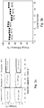
Figure 1 reports the electrochemical characteristics of the DEMETFSI-LiTFSI electrolyte. The Arrhenius plot of the DEMETFSI-LiTFSI electrolyte shown inFig. 1a , within 0°C-60°C temperature range, reveals a conductivity value of 3.5x10⁻⁴ S cm-1 at 0°C that greatly improves by temperature to reach 2.2 x10⁻³ S cm-1 at 30°C, 3.4 x10⁻³ S cm-1 at 40°C and 6.6 x10⁻³ S cm-1 at 60°C, i.e., values considered well suitable for application in high performances lithium ion battery. The inset ofFig. 1a shows the viscosity of the DEMETFSI-LiTFSI electrolyte within the same temperature range. The graph shows a relatively high value at 0°C (above 500 mP s) that rapidly decreases by rising the temperature to 30°C (80 mP s) and to 60°C (24 mP s). The increase of the electrolyte conductivity, directly related to the decreased viscosity, is expected to greatly improve its electrochemical performance in lithium ion batteries.Fig. 1b reports the electrochemical window stability of the electrolyte at various temperatures, i.e. 30°C, 40°C, 60°C. The first cathodic scan reveals an irreversible broad peak associated to solid electrolyte interphase (SEI) film formation at the carbon surface, which limits further decomposition by following cycles (see 2nd cycle in inset ofFig. 1b ). The irreversible peak associated to the SEI formation shifts to higher potential values by increasing the temperature, i.e., from 0.4 V at 30°C to 0.5 V at 40°C and to 0.6 V at 60°C. The higher temperatures may lead, in fact, to faster kinetics of the reductive formation of the SEI layer which takes consequently place at higher potential values. Following the first irreversible peak a second reversible peak appears at about 0.1 V vs Li/Li+, as associated to the lithium uptake into amorphous carbon at the working electrode. The intensity of the peak ascribed to the lithium uptake in the amorphous carbon matrix increases by heating as mostly ascribed to the increased its electrochemical activity at higher temperature. The second cycle (inset ofFig. 1b ) shows only the electrochemical lithium uptake into amorphous carbon without further decomposition processes, thus revealing the stability of the SEI film at the electrode surface. The corresponding anodic scans inFig. 1b indicate a decrease of the oxidative degradation potential of the IL-electrolyte by heating expected by the enhancement of the decomposition reaction kinetics. Accordingly, the DEMETFSI-LiTFSI electrolyte shows a stability extended up to 5.00 V vs Li/Li+ at 30°C, decreasing to 4.87 V vs Li/Li+ at 40°C and finally to 4.68 V vs Li/Li+ at 60°C. The stability of the lithium/electrolyte interface was investigated by monitoring the impedance evolution of symmetrical Li/DEMETFSI-LiTFSI/Li cells at various temperatures. Non-linear least square (NLLSQ) analysis of the Nyquist impedance spectra (see Fig. S1 in the Supplementary Information Section) has been performed, and the obtained time-evolution of the interface resistances at various temperatures reported inFig. 1c . The figure evidences a quite stable trend at 30°C, 40°C as well as at 60°C, with decreased value of the interface resistance by increasing temperatures, i.e., from 200 Ω at 30°C, to 120 Ω at 40°C and finally to 40 Ω at 60°C. This trend may be ascribed to the decrease of the resistivity of the SEI formed at the lithium metal surface by heating. Furthermore, the modest increase of the resistance at the higher temperatures, due to expected higher reactivity of the electrolyte with lithium metal, well suggests a stable lithium/electrolyte interface within the investigated temperature range. The ability of the electrolyte to sustain an efficient lithium dissolution/plating process was investigated by a stripping deposition measurement at various temperatures.Fig. 1d reports the voltage profile of the measurement performed at 0.1 mA cm-2 at 30°C, 40°C, 60°C. According to the above reported tests, the data reveal a decrease of the polarization associated to lithium dissolution/plating process by increasing the temperature, i.e., from a value of about 0.1 V at 30°C to 0.05 V at 40°C and finally to 0.025 V at 60°C. This trend can be associated to several factors, among them: i) increase of the ionic conductivity; ii) decrease of the electrolyte viscosity and iii) decrease of the interface resistance of the cell by heating. Furthermore, the measurement shows a stable polarization upon time, again suggesting a stable lithium/electrolyte interface. - In
Fig. 2 , the DEMETFSI-LiTFSI electrolyte is employed in a lithium oxygen cell according to the present invention, wherein lithium metal was used as anode.Fig. 2a reports the voltage signature of the cell cycled at 100 mA g-1 within 2V and 4 V. The cell shows a flat discharge at about 2.5 V due to the electrochemical deposition of lithium peroxide at the carbon surface, and a delivered capacity of about 13 Ah g-1. This very high capacity leads to a theoretical energy density of about 32.5 kWh kg-1 that is a remarkable value, even considering several reduction factors accounting for the limited mass loading, inactive cell components and battery management system (BMS). The cell shows a good reversibility, and a Coulombic efficiency close to 100%. The reversibility of the electrochemical process is also suggested by the ex-situ XRD study and SEM images reported inFig. 2. Fig. 2b shows the SEM micrograph of the pristine carbon electrode and evidences the typical morphology of the Super-C65 used as cathode material. Upon full discharge process (Fig. 2c ) the SEM micrograph of the cathode reveals the formation of the lithium peroxide with a flat, disk-like shape. The SEM micrograph of the cathode upon full charge (Fig. 2d ) shows the morphology associated to the pristine carbon, as indeed expected by the reversibility of the electrochemical process and the almost complete dissolution of the lithium peroxide formed during discharge. Further proof of the process reversibility is given by ex-situ XRD measurements performed after the (dis-)charge process at the carbon electrode (Fig. 2 e-g ). Indeed, the XRD pattern before cycling (Fig. 2e ) evidences broad reflection peaks at 2θ value of 45 and 50 degree attributed to carbon-based electrode. Two new peaks at 32 and 35 degree associated to Li2O2 (indexed by JCPDS 96-210-0228) appear by full discharge (Fig. 2f ) and almost completely disappear by following charge (Fig. 2g ), thus suggesting a reversible deposition and subsequent dissolution of the lithium peroxide by the electrochemical process, in agreement with the results observed by SEM image (compare panels b-d and e-g inFig 2 ). -
Figure 3a shows the electrochemical performance of the Li/DEMETFSI-LiTFSI/O2 cell galvanostatically cycled by limiting the delivered capacity to 500 mAh g-1 at various operating temperatures, i.e. 30°C 40°C and 60°C. The limited capacity condition used for cycling has been already proposed for lithium oxygen cell as the optimal condition for allowing a stable charge discharge operation. During the first stages at 30°C (Top left ofFig. 3a ) the cell is characterized by stable behaviour and remarkable overlapping of the voltage profiles upon cycling, with a polarization between the (dis)charge processes of about 0.6 V. Increasing the temperature during the following cycles results in a significant polarization decrease, i.e., down to 0.55V at 40°C (Top centre ofFig. 3a ) and to a value as low as 0.45V at 60°C (Top right ofFig. 3a ). This behaviour is expected by the combination of the increased ionic conductivity of the electrolyte, the lower value of the electrode/electrolyte interface resistance as well as by the improved kinetics of the electrochemical reaction at higher temperatures. Lowering back thetemperature 30°C (Fig. 3a bottom left curves) evidences an increase of the cell polarization in respect to the initial cycles (compare withFig. 3a top left curve) as most likely due to possible side reactions at the higher operating temperatures. Likely, further increase of the temperature from 30°C to 40°C (Bottom centre ofFig. 3a ) and to 60°C (Bottom right ofFig. 3a ) leads to notably decreased cell polarization. Accordingly,Fig. 3b reports the evolution of the Li/DEMETFSI-LiTFSI/O2 energy efficiency upon cycles by increasing temperature and evidences the improvement of the cell energy efficiency by heating. Furthermore, the Figure indicates stable trend and only minor effects on the cell performance of the repeated heating/cooling. The Li/DEMETFSI-LiTFSI/O2 cell has been also investigated by increasing the delivered capacity limit up to 1500 mAh g-1, which corresponds to a geometric surface capacity of about 2.4 mA cm-2, at the various temperatures, i.e., 30°C (Fig. 4a ), 40°C (Fig. 4b ), 60°C (Fig. 4c ). Despite the higher capacity, the cell shows a stable cycling and reveals the already mentioned reduction of the cell polarization by increasing the temperature with consequent improvement of the energy efficiency. Remarkably, only limited increase of the cell polarization due to excess deposition of lithium peroxide or side reactions at the lithium side is observed by increasing the capacity limit from 500 to 1500 mAh g-1. -
Figures 4d-f report the SEM micrographs of the carbon cathode upon discharge up to 1500 mAh g-1 at the various operating temperatures (30°C,Fig. 4d , 40°CFig. 4e and 60°CFig. 4f ). The images evidence an evolution of the discharge products micrometric morphology from flat-shape particles at 30 °C to toroidal, flower-shaped particles at 60°C with intermediate morphology comprising both configurations at 40°C. The different morphologies of the discharge products may be ascribed to an electrochemical Li2O2 deposition process following two different pathways involving particles growth both at the electrode surface and into the electrolyte. This reaction mechanism is greatly influenced by the temperature and by the electrolyte ability to stabilize the intermediate superoxide species. In summary, the positive effect of the temperature increase on the cell energy efficiency may be ascribed to an improved kinetic of the electrochemical lithium peroxide deposition process, influencing both reaction pathway and morphology of the formed products. - In
Fig. 5 , the optional replacement of the lithium metal by a Li-ion, carbon coated Fe0.1Zn0.9O (ZFO-C) conversion anode is demonstrated.Figure 5 , reporting the voltage signature of the Li / DEMETFSI-LiTFSI / LiFe0.1Zn0.9O half-cell, evidences the expected sloping voltage profile associated to the reversible conversion/alloy reaction:
Zn0.9Fe0.1O + 2.9Li+ + 2.9e- ↔ 0.9LiZn + 0.1Fe + Li2O (1)
- The half-cell can deliver about 600 mAh g-1, with a satisfactory Columbic efficiency, approaching the electrochemical performances in conventional carbonate based electrolyte. Before the full cell assembling, the anode has been electrochemically fully discharged down to 0.01V and then coupled with the carbon based cathode in order to achieve a lithium ion oxygen cell. The LiFe0.1Zn0.9O/DEMETFSI-LiTFSI/O2 lithium-ion oxygen cell reported in
Fig. 5 shows a (dis-)charge voltage profile reflecting the combination of the flat profiles associated to the Li/O2 electrochemical process (black curve) and the sloping profile of the Li/LiFe0.1Zn0.9O electrochemical process illustrated by the electrochemical reaction (2):
1.45 O2 + 0.9LiZn + 0.1Fe + Li2O ↔ Zn0.9Fe0.1O + 1.45 Li2O2 (2)
- The cell has a working voltage centered at about 1.8 V and delivers a reversible capacity of about 500 mAh g-1.
- The electrolyte solution was prepared by dissolving in a 0.2 mol kg-1 of lithium bis(trifluoromethane)sulfonimide (LiTFSI 3M, battery grade) in a N,N-diethyl-N-(2-methoxyethyl)-N-methylammonium bis(trifluoromethylsulphonyl-imide (DEMETFSI) ionic liquid (IL) in an argon filled glove box, with oxygen and water content lower than 1 ppm. The DEMETFSI ionic liquid was synthesized from N,N-Diethylmethylamine (Sigma Aldrich) and 2-Bromoethyl methyl ether (Sigma Aldrich). After distillation, the two precursors were dissolved in tetrahydrofuran (THF) and kept under continuous stirring at 40°C for one week. The following anion exchange was performed in ultrapure water, using LiTFSI as ionic exchanger in order to obtain the desired product. This was first rinsed with water several times, in order to remove bromide, and finally purified with activated charcoal and alumina using ethylacetate as a solvent. The DEMETFSI ionic liquid and the DEMETFSI-LiTFSI electrolyte were dried under vacuum at 80 °C until the water content was reduced to less than 5 ppm (detection limit) as determined by Karl Fischer titration. The electrolyte conductivity Arrhenius plot was obtained by electrochemical impedance spectroscopy (EIS, Mmates-Biologic) using sealed Pt-black/Pt-black cells (Mmates) with a K value of 1 cm-1 in a Julabo FP50 refrigerated/heating circulator for temperature control. The cell constant was confirmed using a standard 0.1M KCl water solution (Fluka). The viscosity of the DEMETFSI-LiTFSI electrolyte was evaluated at various temperatures in a dry room environment by means of Anton-Paar Physica MCR301 rheometer, applying constant sheer rates, and using a liquid nitrogen based cooling unit and electrical-oven for heating. The lithium/electrolyte interphase stability was evaluated by means of impedance spectroscopy of symmetrical Li/DEME-LiTFSI/Li cells during storage time at various temperature (30, 40, 60 °C). The impedance measurements were performed within frequency ranging from 200 kHz to 10 mHz by applying a 10 mV BIAS. The cycling stability of the lithium metal in the DEMETFSI-LiTFSI electrolyte was evaluated by stripping/deposition measurements using symmetrical Li/DEMETFSI-LiTFSI/Li cells, employing a current of 0.1 mA cm-2 and a deposition-stripping time of 1 hour at various operative temperature (30, 40, 60 °C). The electrochemical anodic stability of the electrolyte was evaluated by linear sweep voltammetry with a scan rate of 0.1 mV s-1, using a Super-C65 working electrode coated on aluminum foil. The cathodic stability was determined by cyclic voltammetry in a 0.01-2 V potential range at 0.1 mV s-1 scan rate employing a Super-C65 working electrode coated on copper foil. The electrochemical window stability was evaluated at
different temperature - The cathodes for the lithium oxygen cycling tests were prepared by doctor-blade technique, casting a slurry composed of C-NERGY Super C65 (Imerys) and PVDF (6020 Solef, Solvay) in an 8:2 weight ratio, dispersed in N-methyl-2-pyrrolidinione (NMP, Aldrich 99.9 %) on a gas diffusion layer (SGL-35BC carbon paper, SGL). After drying, the GDL were punched in disk-shaped electrodes having a diameter of 16 mm, the residual solvent was removed under vacuum at 110 °C overnight. The SP-C65 carbon electrodes loading ranged from 0.5 to 0.8 mg cm-2. The electrochemical characterization was performed using a top-meshed 2032 coin-cell and lithium metal as anode, a sheet of Whatman glass fibre GF/A soaked by the electrolyte as separator and the GDL-SP electrode as cathode.
- Cycling tests were carried out galvanostatically by liming the capacity to 500 and 1500 mAh g-1 (at 50 mA g-1 and 100 mA g-1 current, respectively) at various temperatures (30°C, 40°C, 60°C) as well as by extending the test to a full voltage range, i.e., 2.0 V - 4 V, using a current of 100 mA g-1 at 30°C temperature. All galvanostatic cycling tests were performed using a Maccor 4000 Battery Test System. The specific current and the specific capacity was referred to the SP-C65 carbon mass on the electrodes. All the electrochemical test was carried in thermostatic climatic chamber with a possible deviation of ± 1°C.
- The morphological characterization was performed by ex situ, field emission scanning electron microscopy (SEM, Zeiss LEO1550VP Gemini) and X-Ray diffraction (XRD Bruker D8 Advance diffractometer equipped with a
CuKα source 1=0.154 nm). Prior to the SEM and XRD analyses, the studied electrodes were rinsed using dimethyl carbonate (DMC) in order to remove residual salt and/or ionic liquid. - The carbon coated Fe0.1Zn0.9O2 (ZFO-C) was prepared using a procedure describer in a previous paper. The electrode was obtained by casting a slurry composed by 70%
active material 20% of C-NERGY Super C65 (Imerys) and 10 % PVDF (6020 Solef, Solvay) dispersed in N-methyl-2-pyrrolidinione (NMP, Aldrich 99.9 %) on a cupper foil. After drying, the cupper foil was punched in disk-shaped electrodes having a diameter of 16 mm, the residual solvent was removed under vacuum at 110 °C overnight. The ZFO-C electrodes loading ranged from 2 to 3 mg cm-2. The electrochemical characterization of the anode was performed using a 2032 coin-cell and lithium metal as anode, a sheet of Whatman glass fibre GF/A soaked by the electrolyte as separator, and the ZFO-C electrodes as cathode. The full lithium ion oxygen cell was assembled using the fully lithiated ZFO-C as anode. The ZFO-C electrode was electrochemical prelitiated before assembling the lithium ion oxygen cell. The LixZFO-C/ DEMETFSI-LiTFSI/O2 cell was galvanostatic cycled using a current of 50 mA g-1 and limiting the delivered capacity to 500 mAh g-1 at 30°C temperature.
Claims (9)
- A lithium-air battery comprising:a cathode comprising a gas diffusion layer comprising a solid electronically conductive material coated with carbon black, the gas diffusion layer being at least partially filled with gaseous aira separator comprising an electronically nonconducting filter material arranged between the anode and the cathode, the filter material being at least partially impregnated with a liquid electrolyte, andan anode comprising carbon-coated particles of MxZn1-xO wherein M is a transition metal selected from the group comprising Fe, Co, Ni, Mn and Cu, and 0.02≦x≦0.14,wherein the electrolyte comprises N,N-diethyl-N-methyl-N-(2-methoxyethyl) ammonium bis(trifluoromethylsulfonyl)imid (DEME-TFSI) as hydrophobic, ionic liquid and lithium bis(trifluoromethylsulfonyl)imid (LiTFSI) as lithium salt, and wherein the three phases of gaseous air, liquid electrolyte and solid, electronically conductive material are in contact at at least one point of the gas diffusion layer.
- The lithium-air battery as claimed in the preceding claim, wherein the gas diffusion layer comprises woven or nonwoven carbon fiber fabric.
- The lithium-air battery as claimed in one of the preceding claims, wherein the carbon black has a specific surface are of 30 to 120 g/m2, preferably 40 to 90 g/m2, more preferably 50 to 80 g/m2, in particular 55 to 70 g/m2, as measured according to BET-nitrogen adsorption method ASTM D3037-89
- The lithium-air battery as claimed in one of the preceding claims, wherein the separator is a filter comprising a material selected from the group consisting of glass fibers, cellulose fibers and organic polymer.
- The lithium-air battery as claimed in one of the preceding claims, wherein the molar ratio of LiTFSI to DEME-TFSI is 1: 2 to 1:20.
- The lithium-air battery as claimed in one of the preceding claims, wherein the anode comprises carbon-coated particles of MxZn1-xO wherein M is a transition metal selected from the group comprising Fe and Co, in particular Fe.
- The lithium-air battery as claimed in claim 1, wherein the battery comprises an encapsulation having holes on the side facing the cathode.
- A method for producing the lithium-air battery according to any of claims 1 to 7, comprising:stacking on top of one another under inert gas of:a cathode comprising a gas diffusion layer comprising a solid electronically conductive material coated with carbon black, the gas diffusion layer being at least partially filled with gaseous aira separator comprising an electronically nonconducting filter material, the filter material being at least partially impregnated with a liquid electrolyte, andan anode comprising carbon-coated particles of MxZn1-xO wherein M is a transition metal selected from the group comprising Fe, Co, Ni, Mn and Cu, and 0.02≦x≦0.14,wherein the separator is arranged between the anode and the cathode, wherein the electrolyte comprises N,N-diethyl-N-methyl-N-(2-methoxyethyl) ammonium bis(trifluoromethylsulfonyl) imid as hydrophobic, ionic liquid and lithium bis(trifluoromethylsulfonyl)imid as lithium salt, and wherein the three phases of gaseous air, liquid electrolyte and solid, electronically conductive material are in contact at at least one point of the gas diffusion layer, andencapsulating the lithium-air-battery in such a way that air can penetrate into the gas diffusion layer.
- Use of the lithium-air battery according to one of claims 1 to 7 in a motor vehicle.
Applications Claiming Priority (1)
| Application Number | Priority Date | Filing Date | Title |
|---|---|---|---|
| PCT/EP2017/070375 WO2019029815A1 (en) | 2017-08-10 | 2017-08-10 | Low-polarization lithium oxygen battery |
Publications (2)
| Publication Number | Publication Date |
|---|---|
| EP3665738A1 EP3665738A1 (en) | 2020-06-17 |
| EP3665738B1 true EP3665738B1 (en) | 2021-07-28 |
Family
ID=59631766
Family Applications (1)
| Application Number | Title | Priority Date | Filing Date |
|---|---|---|---|
| EP17752371.9A Active EP3665738B1 (en) | 2017-08-10 | 2017-08-10 | Low-polarization lithium oxygen battery |
Country Status (4)
| Country | Link |
|---|---|
| US (1) | US11271265B2 (en) |
| EP (1) | EP3665738B1 (en) |
| CN (1) | CN111108643B (en) |
| WO (1) | WO2019029815A1 (en) |
Families Citing this family (2)
| Publication number | Priority date | Publication date | Assignee | Title |
|---|---|---|---|---|
| KR20200110902A (en) * | 2019-03-18 | 2020-09-28 | 현대자동차주식회사 | positive electrode for lithium air battery with good stability, manufacturing method of the same and lithium air battery including the same |
| CN114914458B (en) * | 2022-06-16 | 2024-01-05 | 中国科学技术大学 | Air electrode with highly ordered array structure and preparation method thereof |
Family Cites Families (5)
| Publication number | Priority date | Publication date | Assignee | Title |
|---|---|---|---|---|
| US6749648B1 (en) | 2000-06-19 | 2004-06-15 | Nanagram Corporation | Lithium metal oxides |
| US6627058B1 (en) * | 2001-01-17 | 2003-09-30 | E. I. Du Pont De Nemours And Company | Thick film conductor composition for use in biosensors |
| CA2724307A1 (en) * | 2010-12-01 | 2012-06-01 | Hydro-Quebec | Lithium-air battery |
| US20140127596A1 (en) * | 2011-06-24 | 2014-05-08 | Iucf-Hyu(Industry-University Cooperation Foundation Hanyang University) | Lithium-air battery |
| DE102012107199B4 (en) | 2012-08-06 | 2022-05-12 | Westfälische Wilhelms-Universität Münster | Process for producing carbon-coated, metal-doped zinc oxide particles, carbon-coated, metal-doped zinc oxide particles, their use, and electrode material, electrode and electrochemical energy storage device |
-
2017
- 2017-08-10 EP EP17752371.9A patent/EP3665738B1/en active Active
- 2017-08-10 CN CN201780093777.9A patent/CN111108643B/en active Active
- 2017-08-10 WO PCT/EP2017/070375 patent/WO2019029815A1/en unknown
-
2020
- 2020-02-07 US US16/784,407 patent/US11271265B2/en active Active
Also Published As
| Publication number | Publication date |
|---|---|
| EP3665738A1 (en) | 2020-06-17 |
| CN111108643A (en) | 2020-05-05 |
| US11271265B2 (en) | 2022-03-08 |
| WO2019029815A1 (en) | 2019-02-14 |
| US20200176839A1 (en) | 2020-06-04 |
| CN111108643B (en) | 2024-03-08 |
Similar Documents
| Publication | Publication Date | Title |
|---|---|---|
| EP3595056B1 (en) | Battery | |
| US10439212B2 (en) | Aluminum borate coated lithium ion cathode materials | |
| EP0964468B1 (en) | Organic electrolytic battery | |
| EP2592675B1 (en) | Negative active material, method of preparing the negative active material, electrode including the negative active material, and lithium battery including the electrode | |
| CN101964420B (en) | Positive electrode active material, positive electrode, and nonaqueous electrolyte cell | |
| JP2017517835A (en) | High capacity polymer cathode and high energy density rechargeable battery comprising the cathode | |
| CA2810191A1 (en) | Niobium oxide compositions and methods for using same | |
| KR102542649B1 (en) | Negative electrode for rechargeable lithium battery and rechargeable lithium battery including the same | |
| US20110039157A1 (en) | Anodic carbon material for lithium secondary battery, method for manufacturing the same, lithium secondary battery anode, and lithium secondary battery | |
| KR101097244B1 (en) | Negative electrode for lithium battery and lithium battery comprising the same | |
| JP2012104290A (en) | Positive electrode active material for nonaqueous electrolyte battery, positive electrode for nonaqueous electrolyte battery, and nonaqueous electrolyte battery | |
| US9406935B2 (en) | Anode active material and metal ion battery prepared therewith | |
| EP3598536A1 (en) | Active material and battery | |
| KR20130035911A (en) | Positive electrode material, lithium ion secondary battery using thereof, and manufacturing method of positive electrode material | |
| JP5245201B2 (en) | Negative electrode, secondary battery | |
| US12002957B2 (en) | ε-VOPO4 cathode for lithium ion batteries | |
| KR20150022647A (en) | Electrolyte for lithium secondary battery and lithium secondary battery | |
| KR102409850B1 (en) | Method for Fabricating Coating Structures of Sulfide-based Solid Electrolytes Using Solution Process | |
| US11271265B2 (en) | Low-polarization lithium oxygen battery | |
| JP2013089519A (en) | Lithium ion secondary battery | |
| WO2021124651A1 (en) | Non-aqueous electrolyte power storage element and manufacturing method therefor | |
| US20200403224A1 (en) | Lithium molybdate anode material | |
| JP2012084554A (en) | Anode, secondary battery, and method for manufacturing anode | |
| KR102234705B1 (en) | Composite anode active material, anode and lithium battery containing the same, and preparation method thereof | |
| JPWO2014136180A1 (en) | Negative electrode active material for lithium ion secondary battery |
Legal Events
| Date | Code | Title | Description |
|---|---|---|---|
| STAA | Information on the status of an ep patent application or granted ep patent |
Free format text: STATUS: UNKNOWN |
|
| STAA | Information on the status of an ep patent application or granted ep patent |
Free format text: STATUS: THE INTERNATIONAL PUBLICATION HAS BEEN MADE |
|
| PUAI | Public reference made under article 153(3) epc to a published international application that has entered the european phase |
Free format text: ORIGINAL CODE: 0009012 |
|
| STAA | Information on the status of an ep patent application or granted ep patent |
Free format text: STATUS: REQUEST FOR EXAMINATION WAS MADE |
|
| 17P | Request for examination filed |
Effective date: 20200306 |
|
| AK | Designated contracting states |
Kind code of ref document: A1 Designated state(s): AL AT BE BG CH CY CZ DE DK EE ES FI FR GB GR HR HU IE IS IT LI LT LU LV MC MK MT NL NO PL PT RO RS SE SI SK SM TR |
|
| AX | Request for extension of the european patent |
Extension state: BA ME |
|
| DAV | Request for validation of the european patent (deleted) | ||
| DAX | Request for extension of the european patent (deleted) | ||
| GRAP | Despatch of communication of intention to grant a patent |
Free format text: ORIGINAL CODE: EPIDOSNIGR1 |
|
| STAA | Information on the status of an ep patent application or granted ep patent |
Free format text: STATUS: GRANT OF PATENT IS INTENDED |
|
| INTG | Intention to grant announced |
Effective date: 20210421 |
|
| GRAS | Grant fee paid |
Free format text: ORIGINAL CODE: EPIDOSNIGR3 |
|
| GRAA | (expected) grant |
Free format text: ORIGINAL CODE: 0009210 |
|
| STAA | Information on the status of an ep patent application or granted ep patent |
Free format text: STATUS: THE PATENT HAS BEEN GRANTED |
|
| AK | Designated contracting states |
Kind code of ref document: B1 Designated state(s): AL AT BE BG CH CY CZ DE DK EE ES FI FR GB GR HR HU IE IS IT LI LT LU LV MC MK MT NL NO PL PT RO RS SE SI SK SM TR |
|
| REG | Reference to a national code |
Ref country code: GB Ref legal event code: FG4D |
|
| REG | Reference to a national code |
Ref country code: CH Ref legal event code: EP |
|
| REG | Reference to a national code |
Ref country code: AT Ref legal event code: REF Ref document number: 1415522 Country of ref document: AT Kind code of ref document: T Effective date: 20210815 |
|
| REG | Reference to a national code |
Ref country code: IE Ref legal event code: FG4D |
|
| REG | Reference to a national code |
Ref country code: DE Ref legal event code: R096 Ref document number: 602017042928 Country of ref document: DE |
|
| REG | Reference to a national code |
Ref country code: LT Ref legal event code: MG9D |
|
| REG | Reference to a national code |
Ref country code: NL Ref legal event code: MP Effective date: 20210728 |
|
| REG | Reference to a national code |
Ref country code: AT Ref legal event code: MK05 Ref document number: 1415522 Country of ref document: AT Kind code of ref document: T Effective date: 20210728 |
|
| PG25 | Lapsed in a contracting state [announced via postgrant information from national office to epo] |
Ref country code: HR Free format text: LAPSE BECAUSE OF FAILURE TO SUBMIT A TRANSLATION OF THE DESCRIPTION OR TO PAY THE FEE WITHIN THE PRESCRIBED TIME-LIMIT Effective date: 20210728 Ref country code: RS Free format text: LAPSE BECAUSE OF FAILURE TO SUBMIT A TRANSLATION OF THE DESCRIPTION OR TO PAY THE FEE WITHIN THE PRESCRIBED TIME-LIMIT Effective date: 20210728 Ref country code: SE Free format text: LAPSE BECAUSE OF FAILURE TO SUBMIT A TRANSLATION OF THE DESCRIPTION OR TO PAY THE FEE WITHIN THE PRESCRIBED TIME-LIMIT Effective date: 20210728 Ref country code: LT Free format text: LAPSE BECAUSE OF FAILURE TO SUBMIT A TRANSLATION OF THE DESCRIPTION OR TO PAY THE FEE WITHIN THE PRESCRIBED TIME-LIMIT Effective date: 20210728 Ref country code: AT Free format text: LAPSE BECAUSE OF FAILURE TO SUBMIT A TRANSLATION OF THE DESCRIPTION OR TO PAY THE FEE WITHIN THE PRESCRIBED TIME-LIMIT Effective date: 20210728 Ref country code: BG Free format text: LAPSE BECAUSE OF FAILURE TO SUBMIT A TRANSLATION OF THE DESCRIPTION OR TO PAY THE FEE WITHIN THE PRESCRIBED TIME-LIMIT Effective date: 20211028 Ref country code: NL Free format text: LAPSE BECAUSE OF FAILURE TO SUBMIT A TRANSLATION OF THE DESCRIPTION OR TO PAY THE FEE WITHIN THE PRESCRIBED TIME-LIMIT Effective date: 20210728 Ref country code: NO Free format text: LAPSE BECAUSE OF FAILURE TO SUBMIT A TRANSLATION OF THE DESCRIPTION OR TO PAY THE FEE WITHIN THE PRESCRIBED TIME-LIMIT Effective date: 20211028 Ref country code: PT Free format text: LAPSE BECAUSE OF FAILURE TO SUBMIT A TRANSLATION OF THE DESCRIPTION OR TO PAY THE FEE WITHIN THE PRESCRIBED TIME-LIMIT Effective date: 20211129 Ref country code: FI Free format text: LAPSE BECAUSE OF FAILURE TO SUBMIT A TRANSLATION OF THE DESCRIPTION OR TO PAY THE FEE WITHIN THE PRESCRIBED TIME-LIMIT Effective date: 20210728 Ref country code: ES Free format text: LAPSE BECAUSE OF FAILURE TO SUBMIT A TRANSLATION OF THE DESCRIPTION OR TO PAY THE FEE WITHIN THE PRESCRIBED TIME-LIMIT Effective date: 20210728 |
|
| PG25 | Lapsed in a contracting state [announced via postgrant information from national office to epo] |
Ref country code: PL Free format text: LAPSE BECAUSE OF FAILURE TO SUBMIT A TRANSLATION OF THE DESCRIPTION OR TO PAY THE FEE WITHIN THE PRESCRIBED TIME-LIMIT Effective date: 20210728 Ref country code: LV Free format text: LAPSE BECAUSE OF FAILURE TO SUBMIT A TRANSLATION OF THE DESCRIPTION OR TO PAY THE FEE WITHIN THE PRESCRIBED TIME-LIMIT Effective date: 20210728 Ref country code: GR Free format text: LAPSE BECAUSE OF FAILURE TO SUBMIT A TRANSLATION OF THE DESCRIPTION OR TO PAY THE FEE WITHIN THE PRESCRIBED TIME-LIMIT Effective date: 20211029 |
|
| REG | Reference to a national code |
Ref country code: CH Ref legal event code: PL |
|
| REG | Reference to a national code |
Ref country code: BE Ref legal event code: MM Effective date: 20210831 |
|
| PG25 | Lapsed in a contracting state [announced via postgrant information from national office to epo] |
Ref country code: LI Free format text: LAPSE BECAUSE OF NON-PAYMENT OF DUE FEES Effective date: 20210831 Ref country code: DK Free format text: LAPSE BECAUSE OF FAILURE TO SUBMIT A TRANSLATION OF THE DESCRIPTION OR TO PAY THE FEE WITHIN THE PRESCRIBED TIME-LIMIT Effective date: 20210728 Ref country code: CH Free format text: LAPSE BECAUSE OF NON-PAYMENT OF DUE FEES Effective date: 20210831 |
|
| REG | Reference to a national code |
Ref country code: DE Ref legal event code: R097 Ref document number: 602017042928 Country of ref document: DE |
|
| PG25 | Lapsed in a contracting state [announced via postgrant information from national office to epo] |
Ref country code: SM Free format text: LAPSE BECAUSE OF FAILURE TO SUBMIT A TRANSLATION OF THE DESCRIPTION OR TO PAY THE FEE WITHIN THE PRESCRIBED TIME-LIMIT Effective date: 20210728 Ref country code: SK Free format text: LAPSE BECAUSE OF FAILURE TO SUBMIT A TRANSLATION OF THE DESCRIPTION OR TO PAY THE FEE WITHIN THE PRESCRIBED TIME-LIMIT Effective date: 20210728 Ref country code: RO Free format text: LAPSE BECAUSE OF FAILURE TO SUBMIT A TRANSLATION OF THE DESCRIPTION OR TO PAY THE FEE WITHIN THE PRESCRIBED TIME-LIMIT Effective date: 20210728 Ref country code: MC Free format text: LAPSE BECAUSE OF FAILURE TO SUBMIT A TRANSLATION OF THE DESCRIPTION OR TO PAY THE FEE WITHIN THE PRESCRIBED TIME-LIMIT Effective date: 20210728 Ref country code: LU Free format text: LAPSE BECAUSE OF NON-PAYMENT OF DUE FEES Effective date: 20210810 Ref country code: EE Free format text: LAPSE BECAUSE OF FAILURE TO SUBMIT A TRANSLATION OF THE DESCRIPTION OR TO PAY THE FEE WITHIN THE PRESCRIBED TIME-LIMIT Effective date: 20210728 Ref country code: CZ Free format text: LAPSE BECAUSE OF FAILURE TO SUBMIT A TRANSLATION OF THE DESCRIPTION OR TO PAY THE FEE WITHIN THE PRESCRIBED TIME-LIMIT Effective date: 20210728 Ref country code: AL Free format text: LAPSE BECAUSE OF FAILURE TO SUBMIT A TRANSLATION OF THE DESCRIPTION OR TO PAY THE FEE WITHIN THE PRESCRIBED TIME-LIMIT Effective date: 20210728 |
|
| PLBE | No opposition filed within time limit |
Free format text: ORIGINAL CODE: 0009261 |
|
| STAA | Information on the status of an ep patent application or granted ep patent |
Free format text: STATUS: NO OPPOSITION FILED WITHIN TIME LIMIT |
|
| 26N | No opposition filed |
Effective date: 20220429 |
|
| PG25 | Lapsed in a contracting state [announced via postgrant information from national office to epo] |
Ref country code: IT Free format text: LAPSE BECAUSE OF FAILURE TO SUBMIT A TRANSLATION OF THE DESCRIPTION OR TO PAY THE FEE WITHIN THE PRESCRIBED TIME-LIMIT Effective date: 20210728 Ref country code: IE Free format text: LAPSE BECAUSE OF NON-PAYMENT OF DUE FEES Effective date: 20210810 Ref country code: BE Free format text: LAPSE BECAUSE OF NON-PAYMENT OF DUE FEES Effective date: 20210831 |
|
| P01 | Opt-out of the competence of the unified patent court (upc) registered |
Effective date: 20230427 |
|
| PG25 | Lapsed in a contracting state [announced via postgrant information from national office to epo] |
Ref country code: CY Free format text: LAPSE BECAUSE OF FAILURE TO SUBMIT A TRANSLATION OF THE DESCRIPTION OR TO PAY THE FEE WITHIN THE PRESCRIBED TIME-LIMIT Effective date: 20210728 |
|
| PG25 | Lapsed in a contracting state [announced via postgrant information from national office to epo] |
Ref country code: HU Free format text: LAPSE BECAUSE OF FAILURE TO SUBMIT A TRANSLATION OF THE DESCRIPTION OR TO PAY THE FEE WITHIN THE PRESCRIBED TIME-LIMIT; INVALID AB INITIO Effective date: 20170810 |
|
| PGFP | Annual fee paid to national office [announced via postgrant information from national office to epo] |
Ref country code: GB Payment date: 20230824 Year of fee payment: 7 |
|
| PGFP | Annual fee paid to national office [announced via postgrant information from national office to epo] |
Ref country code: FR Payment date: 20230821 Year of fee payment: 7 Ref country code: DE Payment date: 20230801 Year of fee payment: 7 |
|
| PG25 | Lapsed in a contracting state [announced via postgrant information from national office to epo] |
Ref country code: MK Free format text: LAPSE BECAUSE OF FAILURE TO SUBMIT A TRANSLATION OF THE DESCRIPTION OR TO PAY THE FEE WITHIN THE PRESCRIBED TIME-LIMIT Effective date: 20210728 |