EP3665459B1 - Piezoelectric device having at least one piezoelectric element - Google Patents
Piezoelectric device having at least one piezoelectric element Download PDFInfo
- Publication number
- EP3665459B1 EP3665459B1 EP18759239.9A EP18759239A EP3665459B1 EP 3665459 B1 EP3665459 B1 EP 3665459B1 EP 18759239 A EP18759239 A EP 18759239A EP 3665459 B1 EP3665459 B1 EP 3665459B1
- Authority
- EP
- European Patent Office
- Prior art keywords
- piezoelectric
- piezoelectric device
- transition
- piezoelectric element
- support
- Prior art date
- Legal status (The legal status is an assumption and is not a legal conclusion. Google has not performed a legal analysis and makes no representation as to the accuracy of the status listed.)
- Active
Links
- 230000007704 transition Effects 0.000 claims description 45
- 229910052582 BN Inorganic materials 0.000 claims description 8
- PZNSFCLAULLKQX-UHFFFAOYSA-N Boron nitride Chemical compound N#B PZNSFCLAULLKQX-UHFFFAOYSA-N 0.000 claims description 8
- MCMNRKCIXSYSNV-UHFFFAOYSA-N Zirconium dioxide Chemical compound O=[Zr]=O MCMNRKCIXSYSNV-UHFFFAOYSA-N 0.000 claims description 8
- 239000012528 membrane Substances 0.000 claims description 8
- 230000001133 acceleration Effects 0.000 claims description 7
- 230000000694 effects Effects 0.000 claims description 7
- HBMJWWWQQXIZIP-UHFFFAOYSA-N silicon carbide Chemical compound [Si+]#[C-] HBMJWWWQQXIZIP-UHFFFAOYSA-N 0.000 claims description 7
- VYPSYNLAJGMNEJ-UHFFFAOYSA-N Silicium dioxide Chemical compound O=[Si]=O VYPSYNLAJGMNEJ-UHFFFAOYSA-N 0.000 claims description 5
- 229910052814 silicon oxide Inorganic materials 0.000 claims description 3
- 239000011230 binding agent Substances 0.000 claims description 2
- 229910002115 bismuth titanate Inorganic materials 0.000 claims description 2
- 229910052810 boron oxide Inorganic materials 0.000 claims description 2
- JKWMSGQKBLHBQQ-UHFFFAOYSA-N diboron trioxide Chemical compound O=BOB=O JKWMSGQKBLHBQQ-UHFFFAOYSA-N 0.000 claims description 2
- 229910052613 tourmaline Inorganic materials 0.000 claims description 2
- 229940070527 tourmaline Drugs 0.000 claims description 2
- 239000011032 tourmaline Substances 0.000 claims description 2
- 229910000154 gallium phosphate Inorganic materials 0.000 claims 1
- 239000000463 material Substances 0.000 description 18
- 239000013078 crystal Substances 0.000 description 14
- 230000035882 stress Effects 0.000 description 11
- 229910010271 silicon carbide Inorganic materials 0.000 description 5
- 230000006978 adaptation Effects 0.000 description 4
- KGBXLFKZBHKPEV-UHFFFAOYSA-N boric acid Chemical compound OB(O)O KGBXLFKZBHKPEV-UHFFFAOYSA-N 0.000 description 4
- 239000004327 boric acid Substances 0.000 description 4
- 230000006378 damage Effects 0.000 description 3
- 238000005259 measurement Methods 0.000 description 3
- 230000003287 optical effect Effects 0.000 description 3
- 238000010008 shearing Methods 0.000 description 3
- PXHVJJICTQNCMI-UHFFFAOYSA-N Nickel Chemical compound [Ni] PXHVJJICTQNCMI-UHFFFAOYSA-N 0.000 description 2
- 229910004298 SiO 2 Inorganic materials 0.000 description 2
- 239000011888 foil Substances 0.000 description 2
- 230000008646 thermal stress Effects 0.000 description 2
- 229910018072 Al 2 O 3 Inorganic materials 0.000 description 1
- 239000000919 ceramic Substances 0.000 description 1
- 239000011248 coating agent Substances 0.000 description 1
- 238000000576 coating method Methods 0.000 description 1
- 229910052681 coesite Inorganic materials 0.000 description 1
- 230000006835 compression Effects 0.000 description 1
- 238000007906 compression Methods 0.000 description 1
- 238000001816 cooling Methods 0.000 description 1
- 229910052906 cristobalite Inorganic materials 0.000 description 1
- 230000001747 exhibiting effect Effects 0.000 description 1
- 238000010438 heat treatment Methods 0.000 description 1
- 238000004519 manufacturing process Methods 0.000 description 1
- 238000000034 method Methods 0.000 description 1
- 229910052759 nickel Inorganic materials 0.000 description 1
- 230000001590 oxidative effect Effects 0.000 description 1
- 230000036316 preload Effects 0.000 description 1
- 229910052594 sapphire Inorganic materials 0.000 description 1
- 239000010980 sapphire Substances 0.000 description 1
- 229910052710 silicon Inorganic materials 0.000 description 1
- 239000010703 silicon Substances 0.000 description 1
- 239000000377 silicon dioxide Substances 0.000 description 1
- 229910052682 stishovite Inorganic materials 0.000 description 1
- 238000005382 thermal cycling Methods 0.000 description 1
- 229910052905 tridymite Inorganic materials 0.000 description 1
Images
Classifications
-
- G—PHYSICS
- G01—MEASURING; TESTING
- G01L—MEASURING FORCE, STRESS, TORQUE, WORK, MECHANICAL POWER, MECHANICAL EFFICIENCY, OR FLUID PRESSURE
- G01L1/00—Measuring force or stress, in general
- G01L1/16—Measuring force or stress, in general using properties of piezoelectric devices
-
- G—PHYSICS
- G01—MEASURING; TESTING
- G01L—MEASURING FORCE, STRESS, TORQUE, WORK, MECHANICAL POWER, MECHANICAL EFFICIENCY, OR FLUID PRESSURE
- G01L1/00—Measuring force or stress, in general
- G01L1/26—Auxiliary measures taken, or devices used, in connection with the measurement of force, e.g. for preventing influence of transverse components of force, for preventing overload
-
- C—CHEMISTRY; METALLURGY
- C04—CEMENTS; CONCRETE; ARTIFICIAL STONE; CERAMICS; REFRACTORIES
- C04B—LIME, MAGNESIA; SLAG; CEMENTS; COMPOSITIONS THEREOF, e.g. MORTARS, CONCRETE OR LIKE BUILDING MATERIALS; ARTIFICIAL STONE; CERAMICS; REFRACTORIES; TREATMENT OF NATURAL STONE
- C04B35/00—Shaped ceramic products characterised by their composition; Ceramics compositions; Processing powders of inorganic compounds preparatory to the manufacturing of ceramic products
- C04B35/515—Shaped ceramic products characterised by their composition; Ceramics compositions; Processing powders of inorganic compounds preparatory to the manufacturing of ceramic products based on non-oxide ceramics
- C04B35/58—Shaped ceramic products characterised by their composition; Ceramics compositions; Processing powders of inorganic compounds preparatory to the manufacturing of ceramic products based on non-oxide ceramics based on borides, nitrides, i.e. nitrides, oxynitrides, carbonitrides or oxycarbonitrides or silicides
- C04B35/583—Shaped ceramic products characterised by their composition; Ceramics compositions; Processing powders of inorganic compounds preparatory to the manufacturing of ceramic products based on non-oxide ceramics based on borides, nitrides, i.e. nitrides, oxynitrides, carbonitrides or oxycarbonitrides or silicides based on boron nitride
-
- G—PHYSICS
- G01—MEASURING; TESTING
- G01L—MEASURING FORCE, STRESS, TORQUE, WORK, MECHANICAL POWER, MECHANICAL EFFICIENCY, OR FLUID PRESSURE
- G01L19/00—Details of, or accessories for, apparatus for measuring steady or quasi-steady pressure of a fluent medium insofar as such details or accessories are not special to particular types of pressure gauges
- G01L19/04—Means for compensating for effects of changes of temperature, i.e. other than electric compensation
-
- G—PHYSICS
- G01—MEASURING; TESTING
- G01L—MEASURING FORCE, STRESS, TORQUE, WORK, MECHANICAL POWER, MECHANICAL EFFICIENCY, OR FLUID PRESSURE
- G01L23/00—Devices or apparatus for measuring or indicating or recording rapid changes, such as oscillations, in the pressure of steam, gas, or liquid; Indicators for determining work or energy of steam, internal-combustion, or other fluid-pressure engines from the condition of the working fluid
- G01L23/08—Devices or apparatus for measuring or indicating or recording rapid changes, such as oscillations, in the pressure of steam, gas, or liquid; Indicators for determining work or energy of steam, internal-combustion, or other fluid-pressure engines from the condition of the working fluid operated electrically
- G01L23/10—Devices or apparatus for measuring or indicating or recording rapid changes, such as oscillations, in the pressure of steam, gas, or liquid; Indicators for determining work or energy of steam, internal-combustion, or other fluid-pressure engines from the condition of the working fluid operated electrically by pressure-sensitive members of the piezoelectric type
-
- G—PHYSICS
- G01—MEASURING; TESTING
- G01L—MEASURING FORCE, STRESS, TORQUE, WORK, MECHANICAL POWER, MECHANICAL EFFICIENCY, OR FLUID PRESSURE
- G01L9/00—Measuring steady of quasi-steady pressure of fluid or fluent solid material by electric or magnetic pressure-sensitive elements; Transmitting or indicating the displacement of mechanical pressure-sensitive elements, used to measure the steady or quasi-steady pressure of a fluid or fluent solid material, by electric or magnetic means
- G01L9/0041—Transmitting or indicating the displacement of flexible diaphragms
- G01L9/0051—Transmitting or indicating the displacement of flexible diaphragms using variations in ohmic resistance
- G01L9/0052—Transmitting or indicating the displacement of flexible diaphragms using variations in ohmic resistance of piezoresistive elements
-
- G—PHYSICS
- G01—MEASURING; TESTING
- G01L—MEASURING FORCE, STRESS, TORQUE, WORK, MECHANICAL POWER, MECHANICAL EFFICIENCY, OR FLUID PRESSURE
- G01L9/00—Measuring steady of quasi-steady pressure of fluid or fluent solid material by electric or magnetic pressure-sensitive elements; Transmitting or indicating the displacement of mechanical pressure-sensitive elements, used to measure the steady or quasi-steady pressure of a fluid or fluent solid material, by electric or magnetic means
- G01L9/0041—Transmitting or indicating the displacement of flexible diaphragms
- G01L9/008—Transmitting or indicating the displacement of flexible diaphragms using piezoelectric devices
-
- G—PHYSICS
- G01—MEASURING; TESTING
- G01P—MEASURING LINEAR OR ANGULAR SPEED, ACCELERATION, DECELERATION, OR SHOCK; INDICATING PRESENCE, ABSENCE, OR DIRECTION, OF MOVEMENT
- G01P15/00—Measuring acceleration; Measuring deceleration; Measuring shock, i.e. sudden change of acceleration
- G01P15/02—Measuring acceleration; Measuring deceleration; Measuring shock, i.e. sudden change of acceleration by making use of inertia forces using solid seismic masses
- G01P15/08—Measuring acceleration; Measuring deceleration; Measuring shock, i.e. sudden change of acceleration by making use of inertia forces using solid seismic masses with conversion into electric or magnetic values
- G01P15/09—Measuring acceleration; Measuring deceleration; Measuring shock, i.e. sudden change of acceleration by making use of inertia forces using solid seismic masses with conversion into electric or magnetic values by piezoelectric pick-up
-
- H—ELECTRICITY
- H10—SEMICONDUCTOR DEVICES; ELECTRIC SOLID-STATE DEVICES NOT OTHERWISE PROVIDED FOR
- H10N—ELECTRIC SOLID-STATE DEVICES NOT OTHERWISE PROVIDED FOR
- H10N30/00—Piezoelectric or electrostrictive devices
- H10N30/30—Piezoelectric or electrostrictive devices with mechanical input and electrical output, e.g. functioning as generators or sensors
- H10N30/302—Sensors
-
- H—ELECTRICITY
- H10—SEMICONDUCTOR DEVICES; ELECTRIC SOLID-STATE DEVICES NOT OTHERWISE PROVIDED FOR
- H10N—ELECTRIC SOLID-STATE DEVICES NOT OTHERWISE PROVIDED FOR
- H10N30/00—Piezoelectric or electrostrictive devices
- H10N30/80—Constructional details
- H10N30/85—Piezoelectric or electrostrictive active materials
- H10N30/853—Ceramic compositions
- H10N30/8561—Bismuth based oxides
-
- H—ELECTRICITY
- H10—SEMICONDUCTOR DEVICES; ELECTRIC SOLID-STATE DEVICES NOT OTHERWISE PROVIDED FOR
- H10N—ELECTRIC SOLID-STATE DEVICES NOT OTHERWISE PROVIDED FOR
- H10N30/00—Piezoelectric or electrostrictive devices
- H10N30/80—Constructional details
- H10N30/88—Mounts; Supports; Enclosures; Casings
- H10N30/886—Mechanical prestressing means, e.g. springs
-
- C—CHEMISTRY; METALLURGY
- C04—CEMENTS; CONCRETE; ARTIFICIAL STONE; CERAMICS; REFRACTORIES
- C04B—LIME, MAGNESIA; SLAG; CEMENTS; COMPOSITIONS THEREOF, e.g. MORTARS, CONCRETE OR LIKE BUILDING MATERIALS; ARTIFICIAL STONE; CERAMICS; REFRACTORIES; TREATMENT OF NATURAL STONE
- C04B2235/00—Aspects relating to ceramic starting mixtures or sintered ceramic products
- C04B2235/02—Composition of constituents of the starting material or of secondary phases of the final product
- C04B2235/30—Constituents and secondary phases not being of a fibrous nature
- C04B2235/32—Metal oxides, mixed metal oxides, or oxide-forming salts thereof, e.g. carbonates, nitrates, (oxy)hydroxides, chlorides
- C04B2235/3231—Refractory metal oxides, their mixed metal oxides, or oxide-forming salts thereof
- C04B2235/3244—Zirconium oxides, zirconates, hafnium oxides, hafnates, or oxide-forming salts thereof
-
- C—CHEMISTRY; METALLURGY
- C04—CEMENTS; CONCRETE; ARTIFICIAL STONE; CERAMICS; REFRACTORIES
- C04B—LIME, MAGNESIA; SLAG; CEMENTS; COMPOSITIONS THEREOF, e.g. MORTARS, CONCRETE OR LIKE BUILDING MATERIALS; ARTIFICIAL STONE; CERAMICS; REFRACTORIES; TREATMENT OF NATURAL STONE
- C04B2235/00—Aspects relating to ceramic starting mixtures or sintered ceramic products
- C04B2235/02—Composition of constituents of the starting material or of secondary phases of the final product
- C04B2235/30—Constituents and secondary phases not being of a fibrous nature
- C04B2235/34—Non-metal oxides, non-metal mixed oxides, or salts thereof that form the non-metal oxides upon heating, e.g. carbonates, nitrates, (oxy)hydroxides, chlorides
- C04B2235/3409—Boron oxide, borates, boric acids, or oxide forming salts thereof, e.g. borax
-
- C—CHEMISTRY; METALLURGY
- C04—CEMENTS; CONCRETE; ARTIFICIAL STONE; CERAMICS; REFRACTORIES
- C04B—LIME, MAGNESIA; SLAG; CEMENTS; COMPOSITIONS THEREOF, e.g. MORTARS, CONCRETE OR LIKE BUILDING MATERIALS; ARTIFICIAL STONE; CERAMICS; REFRACTORIES; TREATMENT OF NATURAL STONE
- C04B2235/00—Aspects relating to ceramic starting mixtures or sintered ceramic products
- C04B2235/02—Composition of constituents of the starting material or of secondary phases of the final product
- C04B2235/30—Constituents and secondary phases not being of a fibrous nature
- C04B2235/34—Non-metal oxides, non-metal mixed oxides, or salts thereof that form the non-metal oxides upon heating, e.g. carbonates, nitrates, (oxy)hydroxides, chlorides
- C04B2235/3418—Silicon oxide, silicic acids, or oxide forming salts thereof, e.g. silica sol, fused silica, silica fume, cristobalite, quartz or flint
-
- C—CHEMISTRY; METALLURGY
- C04—CEMENTS; CONCRETE; ARTIFICIAL STONE; CERAMICS; REFRACTORIES
- C04B—LIME, MAGNESIA; SLAG; CEMENTS; COMPOSITIONS THEREOF, e.g. MORTARS, CONCRETE OR LIKE BUILDING MATERIALS; ARTIFICIAL STONE; CERAMICS; REFRACTORIES; TREATMENT OF NATURAL STONE
- C04B2235/00—Aspects relating to ceramic starting mixtures or sintered ceramic products
- C04B2235/02—Composition of constituents of the starting material or of secondary phases of the final product
- C04B2235/30—Constituents and secondary phases not being of a fibrous nature
- C04B2235/38—Non-oxide ceramic constituents or additives
- C04B2235/3817—Carbides
- C04B2235/3826—Silicon carbides
-
- C—CHEMISTRY; METALLURGY
- C04—CEMENTS; CONCRETE; ARTIFICIAL STONE; CERAMICS; REFRACTORIES
- C04B—LIME, MAGNESIA; SLAG; CEMENTS; COMPOSITIONS THEREOF, e.g. MORTARS, CONCRETE OR LIKE BUILDING MATERIALS; ARTIFICIAL STONE; CERAMICS; REFRACTORIES; TREATMENT OF NATURAL STONE
- C04B2235/00—Aspects relating to ceramic starting mixtures or sintered ceramic products
- C04B2235/02—Composition of constituents of the starting material or of secondary phases of the final product
- C04B2235/30—Constituents and secondary phases not being of a fibrous nature
- C04B2235/38—Non-oxide ceramic constituents or additives
- C04B2235/3852—Nitrides, e.g. oxynitrides, carbonitrides, oxycarbonitrides, lithium nitride, magnesium nitride
- C04B2235/386—Boron nitrides
-
- C—CHEMISTRY; METALLURGY
- C04—CEMENTS; CONCRETE; ARTIFICIAL STONE; CERAMICS; REFRACTORIES
- C04B—LIME, MAGNESIA; SLAG; CEMENTS; COMPOSITIONS THEREOF, e.g. MORTARS, CONCRETE OR LIKE BUILDING MATERIALS; ARTIFICIAL STONE; CERAMICS; REFRACTORIES; TREATMENT OF NATURAL STONE
- C04B2235/00—Aspects relating to ceramic starting mixtures or sintered ceramic products
- C04B2235/02—Composition of constituents of the starting material or of secondary phases of the final product
- C04B2235/30—Constituents and secondary phases not being of a fibrous nature
- C04B2235/42—Non metallic elements added as constituents or additives, e.g. sulfur, phosphor, selenium or tellurium
- C04B2235/428—Silicon
-
- C—CHEMISTRY; METALLURGY
- C04—CEMENTS; CONCRETE; ARTIFICIAL STONE; CERAMICS; REFRACTORIES
- C04B—LIME, MAGNESIA; SLAG; CEMENTS; COMPOSITIONS THEREOF, e.g. MORTARS, CONCRETE OR LIKE BUILDING MATERIALS; ARTIFICIAL STONE; CERAMICS; REFRACTORIES; TREATMENT OF NATURAL STONE
- C04B2235/00—Aspects relating to ceramic starting mixtures or sintered ceramic products
- C04B2235/70—Aspects relating to sintered or melt-casted ceramic products
- C04B2235/72—Products characterised by the absence or the low content of specific components, e.g. alkali metal free alumina ceramics
- C04B2235/728—Silicon content
-
- C—CHEMISTRY; METALLURGY
- C04—CEMENTS; CONCRETE; ARTIFICIAL STONE; CERAMICS; REFRACTORIES
- C04B—LIME, MAGNESIA; SLAG; CEMENTS; COMPOSITIONS THEREOF, e.g. MORTARS, CONCRETE OR LIKE BUILDING MATERIALS; ARTIFICIAL STONE; CERAMICS; REFRACTORIES; TREATMENT OF NATURAL STONE
- C04B2235/00—Aspects relating to ceramic starting mixtures or sintered ceramic products
- C04B2235/70—Aspects relating to sintered or melt-casted ceramic products
- C04B2235/74—Physical characteristics
- C04B2235/76—Crystal structural characteristics, e.g. symmetry
- C04B2235/767—Hexagonal symmetry, e.g. beta-Si3N4, beta-Sialon, alpha-SiC or hexa-ferrites
Landscapes
- Physics & Mathematics (AREA)
- General Physics & Mathematics (AREA)
- Engineering & Computer Science (AREA)
- Chemical & Material Sciences (AREA)
- Ceramic Engineering (AREA)
- Manufacturing & Machinery (AREA)
- Materials Engineering (AREA)
- Structural Engineering (AREA)
- Organic Chemistry (AREA)
- Combustion & Propulsion (AREA)
- Measuring Fluid Pressure (AREA)
Description
Die Erfindung betrifft eine piezoelektrische Vorrichtung mit zumindest einem piezoelektrischen Element, welches eine zu einem Krafteinleitelement ausgerichtete Auflageebene aufweist, wobei bei einer thermischen Belastung der piezoelektrischen Vorrichtung in der Auflageebene Ausdehnungsunterschiede zwischen dem piezoelektrischen Element und dem Krafteinleitelement auftreten, wobei zwischen dem piezoelektrischen Element und dem Krafteinleitelement mindestens ein Übergangselement angeordnet ist.The invention relates to a piezoelectric device with at least one piezoelectric element, which has a support plane aligned with a force application element, with thermal stress on the piezoelectric device in the support plane causing expansion differences between the piezoelectric element and the force application element, with between the piezoelectric element and the force application element at least one transition element is arranged.
Bei Kraftmesselementen, Drucksensoren, Beschleunigungs- und Scherkraftsensoren die piezoelektrische Kristallelemente aufweisen, tritt eine Eigenschaft dieser Materialien negativ zutage, nämlich Ausdehnungsunterschiede zu angrenzenden Materialien bei thermischer Belastung, sowie die Anisotropie einiger Stoffwerte, wie Wärmedehnung oder Querdehnung unter mechanischer Spannung.In the case of force measuring elements, pressure sensors, acceleration and shear force sensors that have piezoelectric crystal elements, one property of these materials comes to light negatively, namely expansion differences to adjacent materials under thermal stress, as well as the anisotropy of some material properties, such as thermal expansion or transverse expansion under mechanical stress.
An das eigentliche piezoelektrische Messelement schließt praktisch immer ein Gehäuse, ein Auflager, ein Druckstempel bzw. ein krafteinleitendes Element an, wobei bei diesen Bauteilen ein Wärmedehnverhalten oder Anisotropien in vergleichbarer Größe, wie bei vielen der in Frage kommenden Piezokristallen kaum zu finden sind. Insbesondere im Übergangsbereich vom anisotropen Kristallelement zum isotropen Auflager treten daher schädliche Scherkräfte und Scherspannungen auf. Einerseits kann dadurch das Kristallelement beim Aufheizen aufgrund der größeren Dehnung des Auflagermaterials zerreißen, andererseits erfolgt ein Rutschen des Kristallelements über die Auflage entlang der Kristallrichtung mit größeren Dehnung und ein anschließendes Zerreißen des Kristallelements beim Abkühlen.The actual piezoelectric measuring element is almost always followed by a housing, a support, a pressure plunger or a force-introducing element, with these components hardly ever exhibiting thermal expansion behavior or anisotropies of a comparable size to many of the piezoelectric crystals in question. Damaging shear forces and shear stresses therefore occur, particularly in the transition area from the anisotropic crystal element to the isotropic support. On the one hand, this can cause the crystal element to tear when heated due to the greater expansion of the support material, and on the other hand the crystal element slips over the support along the crystal direction with greater expansion and the crystal element then tears when it cools down.
Bei der Erwärmung oder Abkühlung unter Druckbelastung bzw. Vorspannung kommt es zum reibungsbehafteten Gleiten der Bauteile aufeinander oder zu starken Verspannungen sowohl des Auflagers als auch des Messelementes, da isotropes und anisotropes Material bestenfalls in einer Richtung dehnungsangepasst sein können. Meist wurde bisher das Material eines Druckstückes oder Auflagers so gewählt, dass sein Wärmedehnungskoeffizient ebenso wie sein Querdehnungskoeffizient zwischen den jeweiligen Extremwerten des Kristallelements - gemessen in der Ebene der Kontaktfläche - liegt, sodass auf diese Weise eine gewisse Beschränkung der Verspannungen bzw. der Gleitvorgänge erreicht werden konnte.When heating or cooling under pressure or preload, the components slide on each other with friction or there is strong tension in both the support and the measuring element, since isotropic and anisotropic materials can at best be stretch-adapted in one direction. Up to now, the material of a pressure piece or support has usually been selected in such a way that its coefficient of thermal expansion as well as its coefficient of transverse expansion lies between the respective extreme values of the crystal element - measured in the plane of the contact surface - so that in this way a certain limitation of the stresses or sliding processes can be achieved could.
Die durch die Anisotropie und das unterschiedliche Wärmedehnverhalten hervorgerufenen Spannungen können zur Zerstörung des Auflagers oder des piezoelektrischen Kristallelements führen, letzteres vor allem bei scheibenförmigen Messelementen, angeordnet in Stapeln mit mehreren Messelementen, wie sie bei der Nutzung des sogenannten longitudinalen Piezoeffektes (Ladungsabnahme erfolgt in der Druckfläche) verwendet werden. Die über die Auflage- bzw. Kontaktflächen anliegenden Reibungskräfte wirken hier auf einen normal zu diesen Kräften verhältnismäßig geringen Querschnitt der Kristallelemente, was zum Bruch der Messelemente bei thermischer Wechselbelastung führen kann.The stresses caused by the anisotropy and the different thermal expansion behavior can lead to the destruction of the support or the piezoelectric crystal element, the latter especially in the case of disc-shaped measuring elements arranged in stacks with several measuring elements, as is the case with the Use of the so-called longitudinal piezo effect (charge decrease takes place in the pressure area). The frictional forces applied via the support or contact surfaces act here on a relatively small cross-section of the crystal elements normal to these forces, which can lead to breakage of the measuring elements in the event of thermal cycling.
Weiters wird durch Verspannungen des Kristalls auch dessen Ladungsabgabe, d.h. das Messsignal beeinflusst. Beispielsweise kann es in Teilen der Druckfläche zwischen Kristallelement und Auflager zu reibungsbehaftetem Gleiten und damit zu Hystereseerscheinungen im Messsignal kommen, die natürlich vermieden werden müssen.Furthermore, the charge emission, i.e. the measurement signal, is influenced by the stress of the crystal. For example, in parts of the pressure surface between the crystal element and the support, there can be frictional sliding and thus hysteresis phenomena in the measurement signal, which of course must be avoided.
Im Zusammenhang mit dieser Problematik wird in der
Beispielsweise weisen die dem piezoelektrischen Messelement zugekehrten Endbereiche beider Auflager aus einem isotropen Material stegförmige Elemente oder Rollen auf, deren Wärme- und Querdehnung in Längsrichtung an jene des piezoelektrischen Messelementes angepasst ist. Die Fertigung derartiger Endbereiche ist allerdings aufwändig und die Anpassung der Wärme- und Querdehnung in Längsrichtung für viele Materialkombinationen nicht möglich.For example, the end regions of both supports facing the piezoelectric measuring element have web-shaped elements or rollers made of an isotropic material, whose thermal and transverse expansion in the longitudinal direction is adapted to that of the piezoelectric measuring element. However, the production of such end regions is complex and the adaptation of the thermal and transverse expansion in the longitudinal direction is not possible for many material combinations.
Ein anderer Lösungsansatz wird in der
Der Ausgleich der unterschiedlichen thermischen Ausdehnung wird beispielsweise in der
Dieser Lösungsansatz ist jedoch aufwändig und lässt sich nicht immer erfolgreich umsetzen, zumal bisher die Meinung vorherrschte, dass das Auflager möglichst hart ausgeführt sein muss. Typische Materialien für das Auflager waren bisher Nickel-Basiswerkstoffe oder isolierende Keramiken (z.B. Al2O3) oder Saphir.However, this approach is complex and cannot always be successfully implemented, especially since the prevailing opinion was that the support had to be as hard as possible. Typical materials for the support have so far been nickel-based materials or insulating ceramics (eg Al 2 O 3 ) or sapphire.
Aufgabe der vorliegenden Erfindung ist es, die eingangs beschriebenen piezoelektrischen Vorrichtungen derart zu verbessern, dass Scherspannungen und Scherkräfte in den Bereichen zwischen den krafteinleitenden Elementen und dem piezoelektrischen Messelement mit möglichst einfachen Maßnahmen minimiert bzw. weitgehend vermieden werden. Weiters soll die Qualität des Messsignals verbessert werden, wobei insbesondere spontan auftretende Fehlsignale, hervorgerufen durch reibungsbehaftetes Gleiten und Rutschen der piezoelektrischen Elemente an deren Auflagen, vermieden werden soll.The object of the present invention is to improve the piezoelectric devices described at the outset in such a way that shearing stresses and shearing forces in the areas between the force-introducing elements and the piezoelectric measuring element are minimized or largely avoided using the simplest possible measures. Furthermore, the quality of the measurement signal is to be improved, in particular spontaneously occurring false signals, caused by frictional sliding and slipping of the piezoelectric elements on their supports, being avoided.
Erfindungsgemäß wird dies dadurch erreicht, dass das Übergangselement einen E-Modul aufweist, dessen E-Modul-Komponenten c22, c33 in der Auflageebene jeweils kleiner sind, als die entsprechenden E-Modul-Komponenten des piezoelektrischen Elements. Dadurch "dehnt" oder "staucht" das piezoelektrische Element das Übergangselement. Es reduzieren sich daher im piezoelektrischen Element die Spannungswerte, die das piezoelektrische Element schädigen oder zerreißen könnten.According to the invention, this is achieved in that the transition element has an E module whose E module components c 22 , c 33 in the support plane are each smaller than the corresponding E module components of the piezoelectric element. As a result, the piezoelectric element "stretches" or "compresses" the transition element. The voltage values that could damage or tear the piezoelectric element are therefore reduced in the piezoelectric element.
Im Unterschied zu der aus der
Erfindungsgemäß kann bei einer piezoelektrischen Vorrichtung, das zumindest eine piezoelektrische Element eine anisotrope thermische Ausdehnung und einen durch einen Elastizitätstensor EK beschreibbaren, anisotropen E-Modul aufweisen. Dabei ist der E-Modul des Übergangselements kleiner als die der Auflageebene zugeordneten Komponenten c22 und c33 des Elastizitätstensors EK.According to the invention, in a piezoelectric device, the at least one piezoelectric element can have anisotropic thermal expansion and an anisotropic modulus of elasticity that can be described by an elasticity tensor E K . The modulus of elasticity of the transition element is smaller than the components c 22 and c 33 of the elasticity tensor E K associated with the support plane.
Falls auch das Übergangsmaterial, beispielsweise ein Sinterkörper, einen anisotropen E-Modul aufweist, der durch einen Elastizitätstensor EÜ beschreibbar ist, mit 
Zur möglichst verlustfreien Übertragung der Druckkräfte in das piezoelektrische Element weist das Übergangselement in Richtung einer auf das piezoelektrische Element einwirkenden Kraft eine Druckfestigkeit von zumindest 30%, vorzugsweise von über 90%, der Druckfestigkeit des piezoelektrischen Elements auf.In order to transmit the compressive forces into the piezoelectric element with as little loss as possible, the transition element has a compressive strength of at least 30%, preferably more than 90%, of the compressive strength of the piezoelectric element in the direction of a force acting on the piezoelectric element.
Überraschenderweise hat sich gezeigt, dass die geforderten Materialeigenschaften für das Übergangselement (kleiner E-Modul bei gleichzeitig hoher Druckfestigkeit) von einem Sintermaterial erfüllt werden, das großteils (ca. 50% bis 70%) aus gesintertem, hexagonalem Bornitrid besteht (Bezugsquelle: z.B.: HENZE Boron Nitride Products, siehe: www.henze-bnp.de).Surprisingly, it has been shown that the required material properties for the transition element (small modulus of elasticity combined with high compressive strength) are met by a sintered material that consists largely (approx. 50% to 70%) of sintered, hexagonal boron nitride (source: e.g.: HENZE Boron Nitride Products, see: www.henze-bnp.de).
Das Übergangselement aus Bornitrid kann in der piezoelektrischen Vorrichtung mit seinem spezifischen elektrischen Widerstand > 1012 Ohm cm gleichzeitig als elektrisches Isolierelement eingesetzt werden.The transition element made of boron nitride can be used in the piezoelectric device with its electrical resistivity > 10 12 ohm cm at the same time as an electrical insulating element.
Beispielsweise gilt für GaPO4 und einen BN Sinterwerkstoff für den anisotropen E-Modul [GPa] 
Der E-Modul eines Übergangselementes aus gesintertem hexagonalem Bornitrid, Siliciumcarbid und Zirconuim (IV)oxid liegt zwischen 30 GPa und 45 GPa bei einer Druckfestigkeit von über 100 MPa. Der E-Modul von GaPO4 liegt in der Auflageebene bei viel größeren Werten, nämlich in der y-Achse bei 67 GPa und in der z-Achse bei über 100 GPa, sodass der GaPO4- Kristall das Übergangselement stauchen oder dehnen kann, ohne zu brechen. Die Einsatztemperatur des Sintermaterials reicht bis 900°C in oxidierenden Atmosphären und bis 1800°C in inerten Atmosphären. Es ist daher für piezoelektrischen Vorrichtungen (z.B. für Drucksensoren) im Hochtemperaturbereich über 600°C, sowie in speziellen Anwendungen bis über 800°C, bestens geeignet.The modulus of elasticity of a transition element made of sintered hexagonal boron nitride, silicon carbide and zirconium (IV) oxide is between 30 GPa and 45 GPa with a compressive strength of over 100 MPa. The modulus of elasticity of GaPO 4 is much higher in the support plane, namely 67 GPa on the y-axis and over 100 GPa on the z-axis, so that the GaPO 4 crystal can compress or stretch the transition element without to break. The operating temperature of the sintered material reaches up to 900°C in oxidizing atmospheres and up to 1800°C in inert ones atmospheres. It is therefore ideally suited for piezoelectric devices (e.g. for pressure sensors) in the high-temperature range above 600°C and in special applications up to 800°C.
Das Übergangselement besteht großteils (ca. 50% bis 70%) aus gesintertem, hexagonalem Bornitrid (hBN) und kann Anteile an Siliciumcarbid (SiC), Zirconuim(IV)oxid (ZrO2) und/oder Siliciumoxid (SiO2) enthalten. Weiters kann als Bindemittel Boroxid enthalten sein, sowie Spuren von Silicium und Borsäure.The transition element consists largely (about 50% to 70%) of sintered, hexagonal boron nitride (hBN) and can contain portions of silicon carbide (SiC), zirconium(IV) oxide (ZrO 2 ) and/or silicon oxide (SiO 2 ). Boron oxide can also be present as a binder, as well as traces of silicon and boric acid.
Das Übergangselement kann zusammen mit dem piezoelektrischen Element vorgespannt sein, um Scherkräfte normal zur Vorspannrichtung aufzunehmen.The transition element may be biased together with the piezoelectric element to absorb shear forces normal to the biasing direction.
Beispielhafte Angaben zu geeigneten Materialien für das Übergangselement:
- 1) Sinterkörper aus ca. 70% hBN, ca. 20% ZrO2, ca. 10% SiC samt Spuren von Si und Borsäure.
- 2) Sinterkörper aus ca. 50% hBN, ca. 43% ZrO2, ca. 7% SiC samt Spuren von Si und Borsäure.
- 3) Sinterkörper aus ca. 60% hBN, ca. 40% SiO2 samt Spuren von Borsäure.
- 1) Sintered body made of approx. 70% hBN, approx. 20% ZrO 2 , approx. 10% SiC including traces of Si and boric acid.
- 2) Sintered body made of approx. 50% hBN, approx. 43% ZrO 2 , approx. 7% SiC including traces of Si and boric acid.
- 3) Sintered body made from approx. 60% hBN, approx. 40% SiO 2 including traces of boric acid.
Es ist auch möglich ein Übergangselement mit einem anisotropen E-Modul (beispielsweise hexagonales Bornitrid mit anisotropem E-Modul), derart zu orientieren, dass die anisotrope thermische Ausdehnung des piezoelektrischen Elementes in dessen Auflageebene optimal kompensiert wird.It is also possible to orient a transition element with an anisotropic modulus of elasticity (for example hexagonal boron nitride with an anisotropic modulus of elasticity) in such a way that the anisotropic thermal expansion of the piezoelectric element in its support plane is optimally compensated.
Das piezoelektrische Element kann beispielsweise aus GaPO4, Langasit, Langatat oder Turmalin bestehen oder aus einer Piezokeramik, beispielsweise aus Bismuthtitanat.The piezoelectric element can consist of GaPO 4 , langasite, langatate or tourmaline, for example, or of a piezoceramic, for example bismuth titanate.
Die Erfindung wird im Folgenden an Hand von Ausführungsbeispielen näher erläutert. Es zeigen:
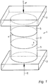
- Fig. 1
- eine erfindungsgemäße piezoelektrische Vorrichtung in einer schematischen, dreidimensionalen Darstellung;
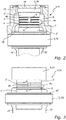
- Fig. 2
- eine erste Ausführungsvariante der Erfindung anhand eines Drucksensors (longitudinaler Piezoeffekt) in einer teilweisen Schnittdarstellung;
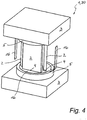
- Fig. 3
- eine zweite Ausführungsvariante der Erfindung anhand eines Kraftoder Beschleunigungssensor in einer seitlichen Ansicht;
- Fig. 4
- eine dritte Ausführungsvariante der Erfindung anhand eines Drucksensors (transversaler Piezoeffekt) in einer teilweisen Schnittdarstellung;
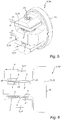
- Fig. 5
- eine vierte Ausführungsvariante der Erfindung anhand eines Beschleunigungs- oder Vibrationssensor in einer dreidimensionalen Darstellung; sowie
- Fig. 6
- eine vereinfachte Seitenansicht der vierten Ausführungsvariante.
- 1
- a piezoelectric device according to the invention in a schematic, three-dimensional representation;
- 2
- a first embodiment of the invention based on a pressure sensor (longitudinal piezo effect) in a partial sectional view;
- 3
- a second embodiment of the invention based on a force or acceleration sensor in a side view;
- 4
- a third embodiment of the invention based on a pressure sensor (transverse piezo effect) in a partial sectional view;
- figure 5
- a fourth embodiment of the invention based on an acceleration or vibration sensor in a three-dimensional representation; such as
- 6
- a simplified side view of the fourth embodiment variant.
Funktionsgleiche Teile sind in den Ausführungsvarianten mit gleichen Bezugszeichen versehen.Parts with the same function are provided with the same reference symbols in the design variants.
Die in
Die in
Der Durchmesser des Übergangselements entspricht im Wesentlichen dem Durchmesser der piezoelektrischen Elemente, wobei die piezoelektrische Vorrichtung gemäß
Das Gehäuse des Drucksensors 10 ist mit dem Randbereich der Sensormembran 11 verschweißt und an einem Zentrierflansch 15 des Auflagers 14 befestigt.The housing of the pressure sensor 10 is welded to the edge area of the
Die Übergangselemente 5 dienen gleichzeitig als elektrische Isolierelemente. Gleichnamige Ladungen an den piezoelektrischen Elementen werden über dünne, duktile Elektrodenbleche 16 aus einem Folienmaterial gesammelt und mittels Signalleitungen 17 abgeleitet. In den
Die in
Die in
Die in den
Die elektrische Kontaktierung erfolgt über dünne Elektrodenbleche 16 aus einem Folienmaterial.The electrical contact is made via
Claims (14)
- Piezoelectric device having at least one piezoelectric element (2) which has a support plane (4) aligned with a force introduction element (3), wherein expansion differences occur between the piezoelectric element (2) and the force introduction element (3) when the piezoelectric device is thermally loaded in the support plane (4), wherein at least one transition element (5) is arranged between the piezoelectric element (2) and the force introduction element (3), characterised in that the transition element (5) has a modulus of elasticity whose modulus of elasticity components C22, C33 in the support plane (4) are smaller in each case than the respective modulus of elasticity components of the piezoelectric element (2).
- Piezoelectric device according to claim 1, characterised in that the at least one piezoelectric element (2) has an anisotropic thermal expansion and an anisotropic modulus of elasticity which can be described by an elasticity tensor.
- Piezoelectric device according to claim 1 or 2, characterised in that the transition element (5) has a compressive strength in the direction of a force acting on the piezoelectric element (2) of at least 30%, preferably of more than 90%, of the compressive strength of the piezoelectric element (2).
- Piezoelectric device according to one of claims 1 to 3, characterised in that the transition element (5) together with the piezoelectric element (2) is pretensioned to absorb shear forces.
- Piezoelectric device according to one of claims 1 to 4, characterised in that the transition element (5) consists largely of sintered, hexagonal boron nitride.
- Piezoelectric device according to claim 5, characterised in that the transition element (5) contains proportions of silicon carbide (SiC), zirconium(IV) oxide (ZrO2) and/or silicon oxide (SiO2).
- Piezoelectric device according to claim 5 or 6, characterised in that the transition element (5) contains boron oxide as a binder.
- Piezoelectric device according to one of claims 2 to 7, characterised in that the transition element (5) has an anisotropic modulus of elasticity and is oriented in such a way that the anisotropic thermal expansion of the piezoelectric element (2) is optimally compensated in its support plane (4).
- Piezoelectric device according to one of claims 1 to 8, characterised in that the piezoelectric element (2) is made of GaPO4, langasite, langatate or tourmaline.
- Piezoelectric device according to one of claims 1 to 8, characterised in that the piezoelectric element (2) consists of a piezoceramic, for example of bismuth titanate.
- Piezoelectric device according to one of claims 1 to 10, characterised in that the piezoelectric device is designed to use the longitudinal piezoelectric effect of the piezoelectric element (2) for determining a size, wherein the thickness of the transition element (5) is between 20% and 500%, preferably between 50% and 300%, of the thickness of the piezoelectric element (2) arranged in a stack.
- Piezoelectric device according to one of claims 1 to 10, characterised in that the piezoelectric device is designed to use the transversal piezoelectric effect of the piezoelectric element (2) for determining a size, wherein the thickness of the transition element (5) is between 5% and 200%, preferably between 10% and 50%, of the height of the piezoelectric element (2) arranged upright.
- Piezoelectric device according to one of claims 1 to 12, characterised in that in order to realize a pressure sensor (10) with a sensor membrane (11), a force introduction element (3) is formed as a support (12) of the pressure sensor and a force introduction element (3) is formed as a thrust piece (14) acted upon by the sensor membrane (11), wherein a first transition element (5) is arranged between the support (12) and the piezoelectric element (2) and a second transition element (5) is arranged between the piezoelectric element (2) and the pressure piece (14).
- Piezoelectric device according to one of claims 1 to 11, characterised in that in order to realize a force or acceleration sensor (20), a force introduction element (3) is designed as a support (12) for the force or acceleration sensor and a force introduction element (3) is designed as a seismic mass (21), wherein a first transition element (5) is arranged between the support (12) and the piezoelectric element (2) and a second transition element (5) is arranged between the piezoelectric element (2) and the seismic mass (21).
Applications Claiming Priority (2)
| Application Number | Priority Date | Filing Date | Title |
|---|---|---|---|
| ATA50656/2017A AT520086B1 (en) | 2017-08-07 | 2017-08-07 | PIEZOELECTRIC DEVICE COMPRISING AT LEAST ONE PIEZOELECTRIC ELEMENT |
| PCT/AT2018/060182 WO2019028488A1 (en) | 2017-08-07 | 2018-08-07 | Piezoelectric device having at least one piezoelectric element |
Publications (2)
| Publication Number | Publication Date |
|---|---|
| EP3665459A1 EP3665459A1 (en) | 2020-06-17 |
| EP3665459B1 true EP3665459B1 (en) | 2022-01-12 |
Family
ID=63363802
Family Applications (1)
| Application Number | Title | Priority Date | Filing Date |
|---|---|---|---|
| EP18759239.9A Active EP3665459B1 (en) | 2017-08-07 | 2018-08-07 | Piezoelectric device having at least one piezoelectric element |
Country Status (4)
| Country | Link |
|---|---|
| US (1) | US20230194368A1 (en) |
| EP (1) | EP3665459B1 (en) |
| AT (1) | AT520086B1 (en) |
| WO (1) | WO2019028488A1 (en) |
Families Citing this family (1)
| Publication number | Priority date | Publication date | Assignee | Title |
|---|---|---|---|---|
| EP4325189A1 (en) | 2022-08-19 | 2024-02-21 | Meggitt SA | Piezoelectric sensor device |
Citations (3)
| Publication number | Priority date | Publication date | Assignee | Title |
|---|---|---|---|---|
| DE3824849A1 (en) | 1988-07-21 | 1990-01-25 | Kempten Elektroschmelz Gmbh | PRESSURIZED POLYCRYSTALLINE MIXING MATERIALS BASED ON HEXAGONAL BORNITRIDE, OXIDES AND CARBIDES |
| JP2013174553A (en) | 2012-02-27 | 2013-09-05 | Citizen Finetech Miyota Co Ltd | Pressure detection device, and internal combustion engine equipped with pressure detection device |
| CN104817326A (en) | 2015-04-13 | 2015-08-05 | 中国科学院金属研究所 | Hexagonal boron nitride-ytterbium silicon oxide-silicon dioxide composite material and preparation method |
Family Cites Families (17)
| Publication number | Priority date | Publication date | Assignee | Title |
|---|---|---|---|---|
| US2988728A (en) * | 1953-07-06 | 1961-06-13 | United Geophysical Corp | Piezoelectric hydrophone |
| US3727084A (en) * | 1970-06-29 | 1973-04-10 | Becton Dickinson Co | Accelerometer utilizing shear responsive x-cut lithium niobate |
| AT371255B (en) * | 1972-11-08 | 1983-06-10 | Becton Dickinson Co | ACCELERATOR |
| US4052628A (en) * | 1976-04-19 | 1977-10-04 | Gulton Industries, Inc. | Dynamic, shear-mode piezoelectric pressure sensor |
| FR2448721A1 (en) * | 1979-02-09 | 1980-09-05 | Cartier Jean | PIEZOELECTRIC ACCELEROMETER |
| JPS59216028A (en) * | 1983-05-24 | 1984-12-06 | Junji Isoyama | Pressure indicator for internal combustion engine |
| CH670310A5 (en) * | 1985-04-17 | 1989-05-31 | Kristal Instr Ag | |
| ATE65319T1 (en) * | 1986-11-07 | 1991-08-15 | Kristal Instr Ag | MULTI-COMPONENT DYNAMOMETER. |
| AT403959B (en) * | 1995-12-15 | 1998-07-27 | Avl Verbrennungskraft Messtech | MEASURING ARRANGEMENT WITH A PIEZOELECTRIC, ANISOTROPICAL MEASURING ELEMENT |
| DE10023556A1 (en) * | 2000-05-15 | 2001-11-29 | Festo Ag & Co | Piezo bending transducer and use of the same |
| AT409550B (en) * | 2001-04-23 | 2002-09-25 | Avl List Gmbh | Piezoelectric device used as a piezoelectric sensor or ultrasound converter has an adapting element arranged between the piezoelectric element and the support element |
| JP2008196874A (en) * | 2007-02-09 | 2008-08-28 | Matsushita Electric Ind Co Ltd | Pressure detection element |
| AT506705B1 (en) * | 2008-09-11 | 2009-11-15 | Piezocryst Advanced Sensorics | PIEZOELECTRIC PRESSURE SENSOR |
| US8375793B2 (en) * | 2011-02-10 | 2013-02-19 | Dytran Instruments, Inc. | Accelerometer for high temperature applications |
| DE102012005555B3 (en) * | 2012-03-21 | 2013-08-22 | Audi Ag | Measuring plate for use in bearing surface of slide damper of press for measuring tension-, pressure- or shear forces, has recesses, in which sensors are mounted under pre-tension for measuring forces by pressure piece |
| JP5689523B1 (en) * | 2013-12-18 | 2015-03-25 | 日本写真印刷株式会社 | Touch panel with pressure detector |
| DE102020206480A1 (en) * | 2020-05-25 | 2021-11-25 | Aktiebolaget Skf | Piezoelectric strain sensor unit for a roller bearing |
-
2017
- 2017-08-07 AT ATA50656/2017A patent/AT520086B1/en active
-
2018
- 2018-08-07 US US16/637,336 patent/US20230194368A1/en active Pending
- 2018-08-07 EP EP18759239.9A patent/EP3665459B1/en active Active
- 2018-08-07 WO PCT/AT2018/060182 patent/WO2019028488A1/en unknown
Patent Citations (3)
| Publication number | Priority date | Publication date | Assignee | Title |
|---|---|---|---|---|
| DE3824849A1 (en) | 1988-07-21 | 1990-01-25 | Kempten Elektroschmelz Gmbh | PRESSURIZED POLYCRYSTALLINE MIXING MATERIALS BASED ON HEXAGONAL BORNITRIDE, OXIDES AND CARBIDES |
| JP2013174553A (en) | 2012-02-27 | 2013-09-05 | Citizen Finetech Miyota Co Ltd | Pressure detection device, and internal combustion engine equipped with pressure detection device |
| CN104817326A (en) | 2015-04-13 | 2015-08-05 | 中国科学院金属研究所 | Hexagonal boron nitride-ytterbium silicon oxide-silicon dioxide composite material and preparation method |
Non-Patent Citations (4)
| Title |
|---|
| "Piezoelectric Sensorics", 1 January 2002, SPRINGER, article GAUTSCHI GUSTAV: "Chaters 1, 2 and 3", pages: 1 - 38, XP055974081 |
| "Taschenbuch der Physik", 1 January 1990, CARL VERLAG, article KUCHLING HORST: "Tabelle 9", pages: 26 - 27, 614-615, XP055974070 |
| ANONYMOUS: "Infomaterial", METALLGUSS MERTENS USINGEN, 7 February 2016 (2016-02-07), pages 1 - 33, XP055974075, Retrieved from the Internet <URL:http://www.alu-guss.de/Metallguss_Mertens_Usingen_Infomaterial.pdf> [retrieved on 20221024] |
| ANONYMOUS: "Silica - Silicon Dioxide (SiO2)", AZO MATERIALS, 13 December 2001 (2001-12-13), XP055974072, Retrieved from the Internet <URL:https://www.azom.com/properties.aspx?ArticleID=1114> [retrieved on 20221024] |
Also Published As
| Publication number | Publication date |
|---|---|
| WO2019028488A1 (en) | 2019-02-14 |
| EP3665459A1 (en) | 2020-06-17 |
| US20230194368A1 (en) | 2023-06-22 |
| AT520086B1 (en) | 2019-01-15 |
| AT520086A4 (en) | 2019-01-15 |
Similar Documents
| Publication | Publication Date | Title |
|---|---|---|
| DE102006019942B4 (en) | Force measuring device for measuring the force in solid state actuators, methods for measuring a force and use of the force measuring device | |
| EP1797603B1 (en) | Sensor element having at least one measurement element with piezoelectric and pyroelectric properties | |
| EP2436051B1 (en) | Piezoelectric component | |
| EP3665459B1 (en) | Piezoelectric device having at least one piezoelectric element | |
| AT391369B (en) | PIEZOELECTRIC SENSOR | |
| EP1876434A2 (en) | Device for measuring forces, in particular a pressure sensor and manufacturing method therefore | |
| Jenkins | Fracture in reactor graphite | |
| DE102006023724B4 (en) | Measuring cell arrangement for a pressure sensor with force measuring element made of glass | |
| EP0226742B1 (en) | Pressure transducer for measuring pressures at high temperatures | |
| DE1648782A1 (en) | Piezoelectric transducer, especially for acceleration measurement | |
| DE60313552T2 (en) | Method for producing a strain gauge sensor | |
| EP1704603B1 (en) | Method for producing a correlation between a first state and a second state of a piezoelectric component, and the use of said correlation | |
| EP2529423B1 (en) | Piezo electrical component | |
| EP2789966B1 (en) | Extension measuring sensor | |
| DE102012204853A1 (en) | Method for producing a thin film on a substrate | |
| EP1263060A2 (en) | Manufacturing method for a flat multilayer device and corresponding device | |
| WO2020035384A1 (en) | Ultrasonic vibration device having piezo sensor | |
| DE102005061703A1 (en) | Device for determining and / or monitoring a process variable and method for producing a corresponding sensor unit | |
| DE102010051049B4 (en) | Piezoresistive pressure measuring element and use of the pressure measuring element | |
| DE112022000089T5 (en) | ELEMENT FOR GENERATION OF ELECTRICAL ENERGY FROM VIBRATION | |
| AT403959B (en) | MEASURING ARRANGEMENT WITH A PIEZOELECTRIC, ANISOTROPICAL MEASURING ELEMENT | |
| DE3240666A1 (en) | Apparatus for testing the rheological behaviour of elastoviscous or viscoelastic materials at variable and/or constant temperatures | |
| DE19735666A1 (en) | Mass flux sensor, to monitor for holes in thin substrate, e.g. pipe wall | |
| DE2332764A1 (en) | TEMPERATURE COMPENSATION FOR A TRANSDUCER | |
| DE1945373A1 (en) | Method and device for compensating the pyroelectric effect on electromechanical converters, in particular ferroelectrics |
Legal Events
| Date | Code | Title | Description |
|---|---|---|---|
| STAA | Information on the status of an ep patent application or granted ep patent |
Free format text: STATUS: UNKNOWN |
|
| STAA | Information on the status of an ep patent application or granted ep patent |
Free format text: STATUS: THE INTERNATIONAL PUBLICATION HAS BEEN MADE |
|
| PUAI | Public reference made under article 153(3) epc to a published international application that has entered the european phase |
Free format text: ORIGINAL CODE: 0009012 |
|
| STAA | Information on the status of an ep patent application or granted ep patent |
Free format text: STATUS: REQUEST FOR EXAMINATION WAS MADE |
|
| 17P | Request for examination filed |
Effective date: 20200304 |
|
| AK | Designated contracting states |
Kind code of ref document: A1 Designated state(s): AL AT BE BG CH CY CZ DE DK EE ES FI FR GB GR HR HU IE IS IT LI LT LU LV MC MK MT NL NO PL PT RO RS SE SI SK SM TR |
|
| AX | Request for extension of the european patent |
Extension state: BA ME |
|
| DAV | Request for validation of the european patent (deleted) | ||
| DAX | Request for extension of the european patent (deleted) | ||
| STAA | Information on the status of an ep patent application or granted ep patent |
Free format text: STATUS: EXAMINATION IS IN PROGRESS |
|
| 17Q | First examination report despatched |
Effective date: 20210517 |
|
| GRAP | Despatch of communication of intention to grant a patent |
Free format text: ORIGINAL CODE: EPIDOSNIGR1 |
|
| STAA | Information on the status of an ep patent application or granted ep patent |
Free format text: STATUS: GRANT OF PATENT IS INTENDED |
|
| INTG | Intention to grant announced |
Effective date: 20211026 |
|
| GRAS | Grant fee paid |
Free format text: ORIGINAL CODE: EPIDOSNIGR3 |
|
| GRAA | (expected) grant |
Free format text: ORIGINAL CODE: 0009210 |
|
| STAA | Information on the status of an ep patent application or granted ep patent |
Free format text: STATUS: THE PATENT HAS BEEN GRANTED |
|
| AK | Designated contracting states |
Kind code of ref document: B1 Designated state(s): AL AT BE BG CH CY CZ DE DK EE ES FI FR GB GR HR HU IE IS IT LI LT LU LV MC MK MT NL NO PL PT RO RS SE SI SK SM TR |
|
| REG | Reference to a national code |
Ref country code: GB Ref legal event code: FG4D Free format text: NOT ENGLISH |
|
| REG | Reference to a national code |
Ref country code: CH Ref legal event code: EP |
|
| REG | Reference to a national code |
Ref country code: DE Ref legal event code: R096 Ref document number: 502018008518 Country of ref document: DE |
|
| REG | Reference to a national code |
Ref country code: IE Ref legal event code: FG4D Free format text: LANGUAGE OF EP DOCUMENT: GERMAN |
|
| REG | Reference to a national code |
Ref country code: AT Ref legal event code: REF Ref document number: 1462693 Country of ref document: AT Kind code of ref document: T Effective date: 20220215 |
|
| REG | Reference to a national code |
Ref country code: LT Ref legal event code: MG9D |
|
| REG | Reference to a national code |
Ref country code: NL Ref legal event code: MP Effective date: 20220112 |
|
| PG25 | Lapsed in a contracting state [announced via postgrant information from national office to epo] |
Ref country code: NL Free format text: LAPSE BECAUSE OF FAILURE TO SUBMIT A TRANSLATION OF THE DESCRIPTION OR TO PAY THE FEE WITHIN THE PRESCRIBED TIME-LIMIT Effective date: 20220112 |
|
| PG25 | Lapsed in a contracting state [announced via postgrant information from national office to epo] |
Ref country code: SE Free format text: LAPSE BECAUSE OF FAILURE TO SUBMIT A TRANSLATION OF THE DESCRIPTION OR TO PAY THE FEE WITHIN THE PRESCRIBED TIME-LIMIT Effective date: 20220112 Ref country code: RS Free format text: LAPSE BECAUSE OF FAILURE TO SUBMIT A TRANSLATION OF THE DESCRIPTION OR TO PAY THE FEE WITHIN THE PRESCRIBED TIME-LIMIT Effective date: 20220112 Ref country code: PT Free format text: LAPSE BECAUSE OF FAILURE TO SUBMIT A TRANSLATION OF THE DESCRIPTION OR TO PAY THE FEE WITHIN THE PRESCRIBED TIME-LIMIT Effective date: 20220512 Ref country code: NO Free format text: LAPSE BECAUSE OF FAILURE TO SUBMIT A TRANSLATION OF THE DESCRIPTION OR TO PAY THE FEE WITHIN THE PRESCRIBED TIME-LIMIT Effective date: 20220412 Ref country code: LT Free format text: LAPSE BECAUSE OF FAILURE TO SUBMIT A TRANSLATION OF THE DESCRIPTION OR TO PAY THE FEE WITHIN THE PRESCRIBED TIME-LIMIT Effective date: 20220112 Ref country code: HR Free format text: LAPSE BECAUSE OF FAILURE TO SUBMIT A TRANSLATION OF THE DESCRIPTION OR TO PAY THE FEE WITHIN THE PRESCRIBED TIME-LIMIT Effective date: 20220112 Ref country code: ES Free format text: LAPSE BECAUSE OF FAILURE TO SUBMIT A TRANSLATION OF THE DESCRIPTION OR TO PAY THE FEE WITHIN THE PRESCRIBED TIME-LIMIT Effective date: 20220112 Ref country code: BG Free format text: LAPSE BECAUSE OF FAILURE TO SUBMIT A TRANSLATION OF THE DESCRIPTION OR TO PAY THE FEE WITHIN THE PRESCRIBED TIME-LIMIT Effective date: 20220412 |
|
| PG25 | Lapsed in a contracting state [announced via postgrant information from national office to epo] |
Ref country code: PL Free format text: LAPSE BECAUSE OF FAILURE TO SUBMIT A TRANSLATION OF THE DESCRIPTION OR TO PAY THE FEE WITHIN THE PRESCRIBED TIME-LIMIT Effective date: 20220112 Ref country code: LV Free format text: LAPSE BECAUSE OF FAILURE TO SUBMIT A TRANSLATION OF THE DESCRIPTION OR TO PAY THE FEE WITHIN THE PRESCRIBED TIME-LIMIT Effective date: 20220112 Ref country code: GR Free format text: LAPSE BECAUSE OF FAILURE TO SUBMIT A TRANSLATION OF THE DESCRIPTION OR TO PAY THE FEE WITHIN THE PRESCRIBED TIME-LIMIT Effective date: 20220413 Ref country code: FI Free format text: LAPSE BECAUSE OF FAILURE TO SUBMIT A TRANSLATION OF THE DESCRIPTION OR TO PAY THE FEE WITHIN THE PRESCRIBED TIME-LIMIT Effective date: 20220112 |
|
| PG25 | Lapsed in a contracting state [announced via postgrant information from national office to epo] |
Ref country code: IS Free format text: LAPSE BECAUSE OF FAILURE TO SUBMIT A TRANSLATION OF THE DESCRIPTION OR TO PAY THE FEE WITHIN THE PRESCRIBED TIME-LIMIT Effective date: 20220512 |
|
| REG | Reference to a national code |
Ref country code: DE Ref legal event code: R026 Ref document number: 502018008518 Country of ref document: DE |
|
| PLBI | Opposition filed |
Free format text: ORIGINAL CODE: 0009260 |
|
| PLAX | Notice of opposition and request to file observation + time limit sent |
Free format text: ORIGINAL CODE: EPIDOSNOBS2 |
|
| PG25 | Lapsed in a contracting state [announced via postgrant information from national office to epo] |
Ref country code: SM Free format text: LAPSE BECAUSE OF FAILURE TO SUBMIT A TRANSLATION OF THE DESCRIPTION OR TO PAY THE FEE WITHIN THE PRESCRIBED TIME-LIMIT Effective date: 20220112 Ref country code: SK Free format text: LAPSE BECAUSE OF FAILURE TO SUBMIT A TRANSLATION OF THE DESCRIPTION OR TO PAY THE FEE WITHIN THE PRESCRIBED TIME-LIMIT Effective date: 20220112 Ref country code: RO Free format text: LAPSE BECAUSE OF FAILURE TO SUBMIT A TRANSLATION OF THE DESCRIPTION OR TO PAY THE FEE WITHIN THE PRESCRIBED TIME-LIMIT Effective date: 20220112 Ref country code: EE Free format text: LAPSE BECAUSE OF FAILURE TO SUBMIT A TRANSLATION OF THE DESCRIPTION OR TO PAY THE FEE WITHIN THE PRESCRIBED TIME-LIMIT Effective date: 20220112 Ref country code: DK Free format text: LAPSE BECAUSE OF FAILURE TO SUBMIT A TRANSLATION OF THE DESCRIPTION OR TO PAY THE FEE WITHIN THE PRESCRIBED TIME-LIMIT Effective date: 20220112 Ref country code: CZ Free format text: LAPSE BECAUSE OF FAILURE TO SUBMIT A TRANSLATION OF THE DESCRIPTION OR TO PAY THE FEE WITHIN THE PRESCRIBED TIME-LIMIT Effective date: 20220112 |
|
| 26 | Opposition filed |
Opponent name: KISTLER INSTRUMENTE AG Effective date: 20221011 |
|
| PG25 | Lapsed in a contracting state [announced via postgrant information from national office to epo] |
Ref country code: AL Free format text: LAPSE BECAUSE OF FAILURE TO SUBMIT A TRANSLATION OF THE DESCRIPTION OR TO PAY THE FEE WITHIN THE PRESCRIBED TIME-LIMIT Effective date: 20220112 |
|
| PG25 | Lapsed in a contracting state [announced via postgrant information from national office to epo] |
Ref country code: SI Free format text: LAPSE BECAUSE OF FAILURE TO SUBMIT A TRANSLATION OF THE DESCRIPTION OR TO PAY THE FEE WITHIN THE PRESCRIBED TIME-LIMIT Effective date: 20220112 |
|
| PLBB | Reply of patent proprietor to notice(s) of opposition received |
Free format text: ORIGINAL CODE: EPIDOSNOBS3 |
|
| PG25 | Lapsed in a contracting state [announced via postgrant information from national office to epo] |
Ref country code: MC Free format text: LAPSE BECAUSE OF FAILURE TO SUBMIT A TRANSLATION OF THE DESCRIPTION OR TO PAY THE FEE WITHIN THE PRESCRIBED TIME-LIMIT Effective date: 20220112 |
|
| GBPC | Gb: european patent ceased through non-payment of renewal fee |
Effective date: 20220807 |
|
| PG25 | Lapsed in a contracting state [announced via postgrant information from national office to epo] |
Ref country code: LU Free format text: LAPSE BECAUSE OF NON-PAYMENT OF DUE FEES Effective date: 20220807 |
|
| REG | Reference to a national code |
Ref country code: BE Ref legal event code: MM Effective date: 20220831 |
|
| P01 | Opt-out of the competence of the unified patent court (upc) registered |
Effective date: 20230502 |
|
| PG25 | Lapsed in a contracting state [announced via postgrant information from national office to epo] |
Ref country code: IT Free format text: LAPSE BECAUSE OF FAILURE TO SUBMIT A TRANSLATION OF THE DESCRIPTION OR TO PAY THE FEE WITHIN THE PRESCRIBED TIME-LIMIT Effective date: 20220112 Ref country code: IE Free format text: LAPSE BECAUSE OF NON-PAYMENT OF DUE FEES Effective date: 20220807 Ref country code: FR Free format text: LAPSE BECAUSE OF NON-PAYMENT OF DUE FEES Effective date: 20220831 |
|
| PG25 | Lapsed in a contracting state [announced via postgrant information from national office to epo] |
Ref country code: BE Free format text: LAPSE BECAUSE OF NON-PAYMENT OF DUE FEES Effective date: 20220831 |
|
| PG25 | Lapsed in a contracting state [announced via postgrant information from national office to epo] |
Ref country code: GB Free format text: LAPSE BECAUSE OF NON-PAYMENT OF DUE FEES Effective date: 20220807 |
|
| PGFP | Annual fee paid to national office [announced via postgrant information from national office to epo] |
Ref country code: CH Payment date: 20230902 Year of fee payment: 6 |
|
| PGFP | Annual fee paid to national office [announced via postgrant information from national office to epo] |
Ref country code: DE Payment date: 20230828 Year of fee payment: 6 |
|
| PG25 | Lapsed in a contracting state [announced via postgrant information from national office to epo] |
Ref country code: CY Free format text: LAPSE BECAUSE OF FAILURE TO SUBMIT A TRANSLATION OF THE DESCRIPTION OR TO PAY THE FEE WITHIN THE PRESCRIBED TIME-LIMIT Effective date: 20220112 |