EP3665454B1 - Geometric and radiometric calibration and test apparatus for testing electro-optical thermal-ir instruments - Google Patents
Geometric and radiometric calibration and test apparatus for testing electro-optical thermal-ir instruments Download PDFInfo
- Publication number
- EP3665454B1 EP3665454B1 EP18765193.0A EP18765193A EP3665454B1 EP 3665454 B1 EP3665454 B1 EP 3665454B1 EP 18765193 A EP18765193 A EP 18765193A EP 3665454 B1 EP3665454 B1 EP 3665454B1
- Authority
- EP
- European Patent Office
- Prior art keywords
- thermal
- source
- collimator
- optical
- geometric
- Prior art date
- Legal status (The legal status is an assumption and is not a legal conclusion. Google has not performed a legal analysis and makes no representation as to the accuracy of the status listed.)
- Active
Links
Images


Classifications
-
- G—PHYSICS
- G01—MEASURING; TESTING
- G01J—MEASUREMENT OF INTENSITY, VELOCITY, SPECTRAL CONTENT, POLARISATION, PHASE OR PULSE CHARACTERISTICS OF INFRARED, VISIBLE OR ULTRAVIOLET LIGHT; COLORIMETRY; RADIATION PYROMETRY
- G01J5/00—Radiation pyrometry, e.g. infrared or optical thermometry
- G01J5/02—Constructional details
- G01J5/08—Optical arrangements
- G01J5/0806—Focusing or collimating elements, e.g. lenses or concave mirrors
-
- G—PHYSICS
- G01—MEASURING; TESTING
- G01J—MEASUREMENT OF INTENSITY, VELOCITY, SPECTRAL CONTENT, POLARISATION, PHASE OR PULSE CHARACTERISTICS OF INFRARED, VISIBLE OR ULTRAVIOLET LIGHT; COLORIMETRY; RADIATION PYROMETRY
- G01J5/00—Radiation pyrometry, e.g. infrared or optical thermometry
- G01J5/02—Constructional details
- G01J5/04—Casings
- G01J5/047—Mobile mounting; Scanning arrangements
-
- G—PHYSICS
- G01—MEASURING; TESTING
- G01J—MEASUREMENT OF INTENSITY, VELOCITY, SPECTRAL CONTENT, POLARISATION, PHASE OR PULSE CHARACTERISTICS OF INFRARED, VISIBLE OR ULTRAVIOLET LIGHT; COLORIMETRY; RADIATION PYROMETRY
- G01J5/00—Radiation pyrometry, e.g. infrared or optical thermometry
- G01J5/02—Constructional details
- G01J5/08—Optical arrangements
- G01J5/0808—Convex mirrors
-
- G—PHYSICS
- G01—MEASURING; TESTING
- G01J—MEASUREMENT OF INTENSITY, VELOCITY, SPECTRAL CONTENT, POLARISATION, PHASE OR PULSE CHARACTERISTICS OF INFRARED, VISIBLE OR ULTRAVIOLET LIGHT; COLORIMETRY; RADIATION PYROMETRY
- G01J5/00—Radiation pyrometry, e.g. infrared or optical thermometry
- G01J5/02—Constructional details
- G01J5/08—Optical arrangements
- G01J5/0831—Masks; Aperture plates; Spatial light modulators
-
- G—PHYSICS
- G01—MEASURING; TESTING
- G01J—MEASUREMENT OF INTENSITY, VELOCITY, SPECTRAL CONTENT, POLARISATION, PHASE OR PULSE CHARACTERISTICS OF INFRARED, VISIBLE OR ULTRAVIOLET LIGHT; COLORIMETRY; RADIATION PYROMETRY
- G01J5/00—Radiation pyrometry, e.g. infrared or optical thermometry
- G01J5/52—Radiation pyrometry, e.g. infrared or optical thermometry using comparison with reference sources, e.g. disappearing-filament pyrometer
- G01J5/53—Reference sources, e.g. standard lamps; Black bodies
-
- G—PHYSICS
- G01—MEASURING; TESTING
- G01J—MEASUREMENT OF INTENSITY, VELOCITY, SPECTRAL CONTENT, POLARISATION, PHASE OR PULSE CHARACTERISTICS OF INFRARED, VISIBLE OR ULTRAVIOLET LIGHT; COLORIMETRY; RADIATION PYROMETRY
- G01J5/00—Radiation pyrometry, e.g. infrared or optical thermometry
- G01J5/52—Radiation pyrometry, e.g. infrared or optical thermometry using comparison with reference sources, e.g. disappearing-filament pyrometer
- G01J5/53—Reference sources, e.g. standard lamps; Black bodies
- G01J5/532—Reference sources, e.g. standard lamps; Black bodies using a reference heater of the emissive surface type, e.g. for selectively absorbing materials
Definitions
- the present invention concerns a geometric and radiometric calibration and test apparatus for electro-optical thermal-IR instruments and designed to simulate angularly-extending thermal-IR sources with different geometries and with thermal-IR emissions containing different hot-cold transitions.
- This apparatus constitutes an improved solution for the production of geometric and radiometric calibration and test equipment, generally known as Optical Ground Support Equipment (OGSE).
- OGSE Optical Ground Support Equipment
- This type of OGSE finds advantageous, although not exclusive, application in the production of electro-optical instruments for Assembly Integration and Test (AIT) and Assembly Integration and Verification (AIV) activities in the space/satellite and defence fields.
- OGSE is widely used for geometrically and radiometrically calibrating and testing electro-optical thermal-IR instruments developed both in the space and in the defence fields.
- OGSE uses collimators based on offset parabolas and operate, as a general rule, by projecting, from infinity, an EM point source, commonly known as a source point, the image of which is then processed by the testing system with algorithms for position fixing/image identification and radiation signal measurement.
- EM point source commonly known as a source point
- the source point materializes an elementary source, taking into account that any angularly-extending object can be mathematically represented by the convolution of several source points.
- the convolution approach in principle correct, has significant effects in terms of accuracy, reducing the test to virtual mathematical modelling and not, as is often requested, a direct measurement with optical stimulus, thus deferring the real operational check of the performance to the field test.
- the method of projecting the source point from infinity is not actually easy to use for defining radiometric scenarios that are very complex, static or variable over time and in the angular directions.
- OGSE is equipped with external scanning systems, made with rotating platforms or, in more complex cases, integral with hexapod platforms, in order to scan Units Under Test (UUTs) under different angles of the projected points.
- UUTs Units Under Test
- Some OGSE also exists that reproduces angularly-extending IR sources with sharp hot-cold transitions.
- US 5,265,958 discloses a geometric and radiometric calibration and test apparatus for electro-optical thermal-IR instruments and designed to simulate different angularly-extending thermal-IR sources with different geometries and with thermal-IR emissions containing different hot-cold transitions.
- the apparatus comprises an IR collimator, a thermal-IR source and a kit of masks.
- the object of the present invention is to provide an innovative geometric and radiometric calibration and test apparatus for electro-optical thermal-IR instruments suitable for the accurate (in the geometric and radiometric sense) reproduction of one or more hot-cold transitions in a real scenario.
- This object is achieved by the present invention in so far as it relates to a geometric and radiometric calibration and test apparatus for electro-optical thermal-IR instruments and designed to simulate angularly-extending thermal-IR sources with different geometries and with emissions containing hot-cold transitions, as defined in the appended claims.
- Figure 1 schematically shows a thermal-IR emission of an angularly-extending thermal-IR source in a context where it is statically projected on an electro-optical instrument, or dynamically moved relative thereto, and in which there is a hot-cold transition between two (or more) different temperatures, designated as Thot and Tcold, respectively, the relative intensities of which can have a variable relation, both in terms of relative intensities and of the transition therebetween.
- Figure 1 shows an example of a thermal-IR emission containing a sharp (diffractive) hot-cold transition (unbroken line) and a modulated hot-cold transition, in particular a linear one (broken line).
- the present invention concerns a geometric and radiometric calibration and test apparatus for thermal-IR (8 ⁇ 16 ⁇ m) UUTs, for example those intended to be installed on satellites or aircraft, and designed to simulate angularly-extending thermal-IR sources with different geometries and with emissions containing hot-cold transitions.
- the design provides the apparatus with flexibility in angular and geometric morphology, in radiometry, and in the movement of the thermal-IR source.
- the present invention provides a geometric and radiometric calibration and test apparatus comprising a telecentric wide-angle collimator on the focal plane of which a thermal-IR source is arranged.
- the source is spatially movable to be positionable and freely movable on the focal plane of the collimator and, expediently, to be also movable along the optical axis of the collimator to compensate for variations in focal length as the ambient temperature and the position of the UUT relative to the source, and also to simulate the response of the UUT to the vibrations of the platform on which the UUT is installed.
- An accompanying kit of easily interchangeable masks is also provided, each of which acts as a projected object that provide the wavefront of the thermal-IR radiations emitted by the thermal-IR source with geometric and radiometric properties such as to cause the thermal-IR radiations reproduced on the UUT's entrance pupil to contain different the hot-cold transition morphologies.
- the invention is therefore assimilable to a high-quality IR projector, where the angular extension of the thermal-IR emission is apodizable depending on the masks' shapes and on the law of motion that the source movement mechanism can induce to simulate the operating conditions of dynamic, i.e. temporally transitory, phenomena.
- the present invention significantly broadens the fields of application of existing point projectors, with the possibility of reproducing dynamic scenarios in small, thermally-controlled spaces.
- the geometric and radiometric calibration and test apparatus of the present invention enables real scenarios to be reproduced in terms of radiative contrast and related trajectories, which is difficult and laborious to reduce to simple operations of mathematical convolution of point sources.
- a method of illumination and a geometric and radiometric calibration and test apparatus suitable for industrial use in AIV/AIT lines for the production, calibration and testing of electro-optical thermal-IR instruments, for example, instruments intended to be installed on satellites or apparatuses in the defence sector, will now be described according to a preferred, but not limitative, embodiment of the invention.
- the geometric and radiometric calibration and test apparatus 1 is designed to illuminate an inlet aperture, indicated hereinafter by the term "entrance pupil", of a UUT with angularly-extending thermal-IR radiation containing a hot-cold transition.
- the geometric and radiometric calibration and test apparatus 1 comprises:
- the collimator 2 comprises telecentric collimating optics comprising a pair of spherical positive meniscus lenses orientated such that the concave surfaces face towards the thermal-IR source 3 and towards the UUS's entrance pupil, respectively.
- the meniscus lenses are expediently made of a high electrical and thermal conductivity optical germanium, for example n-doped optical-grade germanium, expediently with resistivity not higher than 3 ohm/cm, with a wide-band non-reflective treatment.
- the collimator 2 has an effective focal length f and a field angle ⁇ , the entrance pupil is placed at a distance q from the vertex of the closest lens, and the lenses are physically set apart at a distance d.
- X and Y are the tangential and sagittal directions normal to the optical axis Z.
- the collimator 2 is so sized as to be telecentric, i.e. such that every emitting point in its focal plane is projected on the UUT's entrance pupil with the same solid angle for each direction, thereby forming a constant radiometric flux as the field angle changes.
- the collimator shown in Figure 2 is sized to respect the specifications of OGSE designed for an electro-optical instrument for spatial application, equipped with the following first-order characteristics:
- the collimator 2 is kept at a constant temperature just above the ambient temperature, stable within 0.5 °C, in order to ensure the repeatability of the radiometric quantity measurements by the UUT.
- the thermal-IR source 3 is designed such that:
- the thermal-IR source 3 may expediently be, but is not limited to being, made by means of a Peltier cell having a hot side facing the meniscus lenses of the collimator 2, and may expediently be, but is not limited to being, made of a high thermal conductivity glass-ceramic material.
- the position of the thermal-IR source 3 may expediently be controlled by a computer programmed with an opportune dedicated software program.
- the thermal stability may be achieved for example by equipping the thermal-IR source 3 with an adequate heat dissipation structure, integral with the thermal-IR source 3.
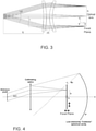
- Figure 4 outlines the structure of the thermal-IR source 3, and shows the presence of a specular concave surface (i.e., with low emissivity in the thermal-IR band) integral with the thermal-IR source 3, so at to move therewith.
- the specular concave surface performs the dual function of heat dissipator for the thermal-IR source 3, and, above all, due to the fact that it is provided with a concave radius of curvature, i.e. provided with optical powers, acts like a Coblenz cavity that condenses the thermal-IR radiation emitted by the collimator 2, thus contributing to the creation of a "cold background" with respect to the thermal-IR source 3.
- the thermal-IR source 3 is implemented by means of a Peltier cell with a hot side facing the collimator 2 and a cold side facing this concave surface
- the latter will be sized (this meaning the radius of curvature and its relative position relative to the cold side of the cell) such that the thermal-IR radiation emitted by the collimator 2 is condensed on the cold side of the Peltier cell, which in this circumstance acts as a simple "mirror” that observes a cold trap (i.e. the side facing the cell's lenses).
- the entire opto-mechanical system must thus expediently comprise hollow walls provided with opportune baffles, to allow the flow of a fluid for thermos-regulating the lenses and the mechanical structure of the illuminator, for example, from an external chiller.
- a computer and dedicated software an integral part of the equipment, thermally controls the thermal-IR source 3.
- the kit of masks 4 to be interchangeably coupled to the thermal-IR source 3 is formed by a series of rolled metal sheets that are appropriately perforated to provide the thermal-IR source 3 with geometries suitable for reproducing an angular apodization of the IR wavefront projected by the system to infinity.
- the masks 4 may, for example, have lateral dimensions of roughly 150 ⁇ 200 mm, and may be made using a thin metal substrate, for example 100-200 ⁇ m, in particular, ferromagnetic for easy application to the thermal-IR source 3 by means of anchoring magnets opportunely arranged on the opposite side of the thermal-IR source 3, namely that facing the Coblenz cavity, so resulting in the accessory mechanics needed for fixing the masks 4 to the thermal-IR source 3 being not seen by the collimator 2.
- the masks may be provided with any geometric shape suitable for reproducing an angular apodization.
- the masks 4 may be perforated in such way as to simulate:
- the useful surface of the masks 4 is such as to ensure, with a margin, that the movement of the thermal-IR source 3 is within the effective UUT's FOV " ⁇ ".
- Radiometric calibrations are those ascribed to the thermal-IR source 3 source only, statically intended, substantially to be carried out through the use of calibrated IR radiometers.
- the emissive elements are, by their nature, susceptible to deterioration, oxidation, and contamination from dust or simply from handling. Therefore, the OGSE is preferably equipped with suitable housings for protection against environmental contamination, and is preferably designed to be easily cleanable, interchangeable and maintainable.
- Geometric calibrations are instead those that assign, at a certain controlled x/y position of the translational platform on which the thermal-IR source 3 is mounted, a precise angular location (for example, dot-like in type B in Figure 5 ) produced by the thermal-IR source 3 on the entrance pupil of the electro-optical instrument to be tested or calibrated.
- kits working in the visible bands can be expediently provided that are intended for:
- the apparatus 1 constitutes a system that, in the case of angularly-extending thermal-IR sources, significantly broadens the application fields of existing point projectors, with the possibility of reproducing dynamic scenarios in small, thermally-controlled spaces.
- the apparatus 1 enables the reproduction of real scenarios in terms both of radiative contrast and of the related trajectories, which is difficult and laborious to trace back to simple operations of mathematical convolution of point sources.
- the apparatus 1 according to the present invention is therefore assimilable to that of a high-quality IR projector, where the angular extension of the thermal-IR source can be modulated according to the form given to the masks and by the laws of motion of the targets that reproduce the operating conditions of transitory (dynamic) phenomena over time.
- the application fields of the invention are numerous and heterogeneous within the scope of the optical-performance characterizations of a UUT.
Landscapes
- Physics & Mathematics (AREA)
- General Physics & Mathematics (AREA)
- Spectroscopy & Molecular Physics (AREA)
- Photometry And Measurement Of Optical Pulse Characteristics (AREA)
- Radiation Pyrometers (AREA)
- Investigating Or Analyzing Materials Using Thermal Means (AREA)
Description
- This application claims priority of
European Patent Application No. 17425088.6 filed on 09/08/2017 - The present invention concerns a geometric and radiometric calibration and test apparatus for electro-optical thermal-IR instruments and designed to simulate angularly-extending thermal-IR sources with different geometries and with thermal-IR emissions containing different hot-cold transitions.
- This apparatus constitutes an improved solution for the production of geometric and radiometric calibration and test equipment, generally known as Optical Ground Support Equipment (OGSE).
- This type of OGSE finds advantageous, although not exclusive, application in the production of electro-optical instruments for Assembly Integration and Test (AIT) and Assembly Integration and Verification (AIV) activities in the space/satellite and defence fields.
- Nowadays, OGSE is widely used for geometrically and radiometrically calibrating and testing electro-optical thermal-IR instruments developed both in the space and in the defence fields.
- Most known OGSE uses collimators based on offset parabolas and operate, as a general rule, by projecting, from infinity, an EM point source, commonly known as a source point, the image of which is then processed by the testing system with algorithms for position fixing/image identification and radiation signal measurement. In fact, the source point materializes an elementary source, taking into account that any angularly-extending object can be mathematically represented by the convolution of several source points.
- The convolution approach, in principle correct, has significant effects in terms of accuracy, reducing the test to virtual mathematical modelling and not, as is often requested, a direct measurement with optical stimulus, thus deferring the real operational check of the performance to the field test.
- The method of projecting the source point from infinity, although general from the mathematical standpoint, is not actually easy to use for defining radiometric scenarios that are very complex, static or variable over time and in the angular directions.
- Many known OGSE is equipped with external scanning systems, made with rotating platforms or, in more complex cases, integral with hexapod platforms, in order to scan Units Under Test (UUTs) under different angles of the projected points.
- This entails, on one hand, the use of expensive and accurate movement systems, in relation to the weight and bulk of the OGSE and/or UUTs, and, on the other hand, the need to recalibrate the UUTs based on the mutual position between the illuminators and the UUTs, because the systems are often subject to the perturbing effects of the system itself and of the environment.
- Some OGSE also exists that reproduces angularly-extending IR sources with sharp hot-cold transitions.
- However, such OGSE appear to be both hardly reconfigurable for different scenarios and hardly usable in dynamic situations.
-
US 5,265,958 discloses a geometric and radiometric calibration and test apparatus for electro-optical thermal-IR instruments and designed to simulate different angularly-extending thermal-IR sources with different geometries and with thermal-IR emissions containing different hot-cold transitions. The apparatus comprises an IR collimator, a thermal-IR source and a kit of masks. - In the field of OGSE, the need is felt to develop methodologies and apparatuses of growing complexity for the geometric and radiometric calibration and testing of electro-optical instruments operating in the infrared-thermal band.
- In fact, while up until a few years ago test and calibration surveys were carried out when an electro-optical instrument was delivered and were generally limited to basic functional tests, today, due to an increasingly competitive scenario, instances of optical characterization of borderline situations, albeit operative and real, clearly emerge.
- To give a few examples:
- electro-optical attitude sensors for satellite use, for example on board Low Earth Orbit (LEO) satellites, are known that allow the attitude of a satellite passing over a stretch of land at low altitude (between 400 and 850 km) to be determined. This operating scenario has forced a substantial reassessment of the observation geometries and the radiometric characteristics of existing OGSE. In fact, at low altitudes, the land strip appears geometrically wide and, in contrast with the surrounding cold space, its thermal-IR emission is highly modulated by oblique viewing factors;
- in the avionics field, complex radiometric characterization surveys might become necessary for electro-optical thermal-IR instruments in order to perform optical measurements in the presence of high temperature gradients superimposed on the observed scene.
- In general, these circumstances, where the checks of performances of electro-optical thermal-IR instruments during operating conditions at the limit of the optical measurement methodologies are requested, have led the Applicant to reconsider illumination methods and the associated equipment for extending radiometric test and calibration configurations to complex operating circumstances.
- The object of the present invention is to provide an innovative geometric and radiometric calibration and test apparatus for electro-optical thermal-IR instruments suitable for the accurate (in the geometric and radiometric sense) reproduction of one or more hot-cold transitions in a real scenario.
- This object is achieved by the present invention in so far as it relates to a geometric and radiometric calibration and test apparatus for electro-optical thermal-IR instruments and designed to simulate angularly-extending thermal-IR sources with different geometries and with emissions containing hot-cold transitions, as defined in the appended claims.
-
-
Figure 1 shows a thermal emission of an angularly-extending, thermal-IR source with a thermal-IR emission containing a hot-cold transition. -
Figure 2 is a 3D representation of a geometric and radiometric calibration and test apparatus for electro-optical thermal-IR instruments according to a preferred embodiment of the present invention; -
Figure 3 shows an optical diagram of a telecentric IR collimator forming part of the apparatus shown inFigure 2 ; -
Figure 4 shows an optical diagram of a paraxial approximation of the apparatus shown inFigure 2 ; and -
Figure 5 shows a kit of interchangeable masks forming part of the apparatus shown inFigure 2 . - The following description is provided to allow a skilled person in the field to implement and use the invention. Various modifications to the embodiments shown will be immediately obvious to experts and the generic principles described herein could be applied to other embodiments and applications without departing from the scope of protection of the present invention as defined in the appended claims. In consequence, the present invention is not intended to be limited to just the embodiments set forth herein, but is to be accorded the widest scope consistent with the principles and features disclosed herein and defined in the appended claims.
-
Figure 1 schematically shows a thermal-IR emission of an angularly-extending thermal-IR source in a context where it is statically projected on an electro-optical instrument, or dynamically moved relative thereto, and in which there is a hot-cold transition between two (or more) different temperatures, designated as Thot and Tcold, respectively, the relative intensities of which can have a variable relation, both in terms of relative intensities and of the transition therebetween. In greater detail,Figure 1 shows an example of a thermal-IR emission containing a sharp (diffractive) hot-cold transition (unbroken line) and a modulated hot-cold transition, in particular a linear one (broken line). - The present invention concerns a geometric and radiometric calibration and test apparatus for thermal-IR (8÷16 µm) UUTs, for example those intended to be installed on satellites or aircraft, and designed to simulate angularly-extending thermal-IR sources with different geometries and with emissions containing hot-cold transitions.
- The design provides the apparatus with flexibility in angular and geometric morphology, in radiometry, and in the movement of the thermal-IR source.
- In a nutshell, the present invention provides a geometric and radiometric calibration and test apparatus comprising a telecentric wide-angle collimator on the focal plane of which a thermal-IR source is arranged. The source is spatially movable to be positionable and freely movable on the focal plane of the collimator and, expediently, to be also movable along the optical axis of the collimator to compensate for variations in focal length as the ambient temperature and the position of the UUT relative to the source, and also to simulate the response of the UUT to the vibrations of the platform on which the UUT is installed. An accompanying kit of easily interchangeable masks is also provided, each of which acts as a projected object that provide the wavefront of the thermal-IR radiations emitted by the thermal-IR source with geometric and radiometric properties such as to cause the thermal-IR radiations reproduced on the UUT's entrance pupil to contain different the hot-cold transition morphologies.
- The invention is therefore assimilable to a high-quality IR projector, where the angular extension of the thermal-IR emission is apodizable depending on the masks' shapes and on the law of motion that the source movement mechanism can induce to simulate the operating conditions of dynamic, i.e. temporally transitory, phenomena.
- In the case of angularly-extending sources with different geometries, the present invention significantly broadens the fields of application of existing point projectors, with the possibility of reproducing dynamic scenarios in small, thermally-controlled spaces.
- The geometric and radiometric calibration and test apparatus of the present invention enables real scenarios to be reproduced in terms of radiative contrast and related trajectories, which is difficult and laborious to reduce to simple operations of mathematical convolution of point sources.
- A method of illumination and a geometric and radiometric calibration and test apparatus suitable for industrial use in AIV/AIT lines for the production, calibration and testing of electro-optical thermal-IR instruments, for example, instruments intended to be installed on satellites or apparatuses in the defence sector, will now be described according to a preferred, but not limitative, embodiment of the invention.
- In the preferred embodiment shown in
Figures 2 ,3 and 4 , the geometric and radiometric calibration and test apparatus 1 is designed to illuminate an inlet aperture, indicated hereinafter by the term "entrance pupil", of a UUT with angularly-extending thermal-IR radiation containing a hot-cold transition. - To illuminate the UUT with an angularly-extending thermal-IR radiation containing a hot-cold transition, the geometric and radiometric calibration and test apparatus 1 comprises:
- a thermal-IR collimator 2 (also referred hereinafter to as projector) having an optical axis Z and a focal plane F arranged on the opposite side of the collimator 2 with respect to the UUT's entrance pupil to be illuminated,
- a thermal-IR source 3 controllably movable relative to the collimator 2 to be arrangeable and displaceable on the focal plane F of the collimator 2, and expediently also displaceable along the optical axis Z of the collimator 2, and operable to radiate thermal-IR radiations towards the collimator 2, and
- a kit of interchangeable masks 4, also known as targets, selectively and removably arrangeable in front of the thermal-IR source 3, so as to be integrally movable therewith, and having geometric and radiometric properties such as to cause the thermal-IR radiation reproduced on the UUT's entrance pupil to contain different hot-cold transitions.
- The collimator 2 comprises telecentric collimating optics comprising a pair of spherical positive meniscus lenses orientated such that the concave surfaces face towards the thermal-IR source 3 and towards the UUS's entrance pupil, respectively.
- The meniscus lenses are expediently made of a high electrical and thermal conductivity optical germanium, for example n-doped optical-grade germanium, expediently with resistivity not higher than 3 ohm/cm, with a wide-band non-reflective treatment.
- The collimator 2 has an effective focal length f and a field angle Ω, the entrance pupil is placed at a distance q from the vertex of the closest lens, and the lenses are physically set apart at a distance d. X and Y are the tangential and sagittal directions normal to the optical axis Z.
- The collimator 2 is so sized as to be telecentric, i.e. such that every emitting point in its focal plane is projected on the UUT's entrance pupil with the same solid angle for each direction, thereby forming a constant radiometric flux as the field angle changes.
- It should be appreciated that, in the detail of the entrance pupil's dislocation, significantly different portions of the optics work at different directions, such portions being constituted by portions of a sphere identifiable by a certain height, indicated by r and referring to the point of intersection of the "chief ray" of the current field with respect to the line containing the optical axis of the collimating optics. This is combined with the specific requirement of using a high thermal and electrical conductivity germanium so as to minimize the creation of spatial thermal gradients that would alter the intensity of the radiation produced as a function of the emission angle.
- This configuration, with optical characteristics at the diffraction limits of the 8-16 micron band, functions as a collimator of a circular area with radius R=f∗tg(Ω/2), with f variable based on the chosen configuration and between 100 and 1000 mm, usable with field angles Ω up to 60° for focal lengths in the order of 100 mm, and, in the case of focal lengths of around a metre, up to approximately 20° overall.
- The collimator shown in
Figure 2 is sized to respect the specifications of OGSE designed for an electro-optical instrument for spatial application, equipped with the following first-order characteristics: - effective focal length - f = 203 mm,
- total field angle - Ω = 40° (+/- 20°), and
- image plane size 2∗R=150 mm approx.
- It should be appreciated that the above-indicated numerical data fails to represent a limitation on the concepts set forth and only represents an example of reduction to practice, it being clear that other numerical configurations may be expediently adopted.
- The collimator 2 is kept at a constant temperature just above the ambient temperature, stable within 0.5 °C, in order to ensure the repeatability of the radiometric quantity measurements by the UUT.
- The thermal-IR source 3 is designed such that:
- it can be mounted on a translational platform (not shown), expediently motorized, movable in the X and Y directions and, expediently, in the Z direction, which directions define a local orthogonal Cartesian reference system (machine coordinates system in jargon),
- it is thermally uncoupled to the collimator 2, and
- it is thermally stable.
- In one embodiment suitable for spatial applications, in particular LEO satellite applications, the thermal-IR source 3 may expediently be, but is not limited to being, made by means of a Peltier cell having a hot side facing the meniscus lenses of the collimator 2, and may expediently be, but is not limited to being, made of a high thermal conductivity glass-ceramic material.
- The position of the thermal-IR source 3 may expediently be controlled by a computer programmed with an opportune dedicated software program.
- The thermal stability may be achieved for example by equipping the thermal-IR source 3 with an adequate heat dissipation structure, integral with the thermal-IR source 3.
-
Figure 4 outlines the structure of the thermal-IR source 3, and shows the presence of a specular concave surface (i.e., with low emissivity in the thermal-IR band) integral with the thermal-IR source 3, so at to move therewith. The specular concave surface performs the dual function of heat dissipator for the thermal-IR source 3, and, above all, due to the fact that it is provided with a concave radius of curvature, i.e. provided with optical powers, acts like a Coblenz cavity that condenses the thermal-IR radiation emitted by the collimator 2, thus contributing to the creation of a "cold background" with respect to the thermal-IR source 3. In other words, assuming that the thermal-IR source 3 is implemented by means of a Peltier cell with a hot side facing the collimator 2 and a cold side facing this concave surface, the latter will be sized (this meaning the radius of curvature and its relative position relative to the cold side of the cell) such that the thermal-IR radiation emitted by the collimator 2 is condensed on the cold side of the Peltier cell, which in this circumstance acts as a simple "mirror" that observes a cold trap (i.e. the side facing the cell's lenses). - The entire opto-mechanical system must thus expediently comprise hollow walls provided with opportune baffles, to allow the flow of a fluid for thermos-regulating the lenses and the mechanical structure of the illuminator, for example, from an external chiller.
- A computer and dedicated software, an integral part of the equipment, thermally controls the thermal-IR source 3.
- The kit of masks 4 to be interchangeably coupled to the thermal-IR source 3 is formed by a series of rolled metal sheets that are appropriately perforated to provide the thermal-IR source 3 with geometries suitable for reproducing an angular apodization of the IR wavefront projected by the system to infinity.
- The masks 4 may, for example, have lateral dimensions of roughly 150÷200 mm, and may be made using a thin metal substrate, for example 100-200 µm, in particular, ferromagnetic for easy application to the thermal-IR source 3 by means of anchoring magnets opportunely arranged on the opposite side of the thermal-IR source 3, namely that facing the Coblenz cavity, so resulting in the accessory mechanics needed for fixing the masks 4 to the thermal-IR source 3 being not seen by the collimator 2.
- The masks may be provided with any geometric shape suitable for reproducing an angular apodization. To mention a few simple examples, the masks 4 may be perforated in such way as to simulate:
- A: an angularly-extending source with a sharp hot/cold transition,
- B: a point source,
- C: a modulated source having a cosine-type projective function that, for example, may be obtained by moving the focal plane F along the direction of the long side of the hole's elliptical profile,
- D: a multipoint source that enables better placement of the focal plane F, simultaneously in several points of the UUT's FOV (Field of View),
- E: a multi-pattern source for Modulation Transfer Function (MTF) measurements, i.e., a contrast function at different spatial frequencies, and
- F: more in general, any morphology suitable for reproducing an outline of any target.
- The useful surface of the masks 4 is such as to ensure, with a margin, that the movement of the thermal-IR source 3 is within the effective UUT's FOV "ω".
- It is to be emphasized the set-up's flexibility, which, depending on the morphology of the masks 4 and their variable positions resulting from movement of the thermal-IR source 3, allows thermal-IR emissions with hot-cold transitions with known transition-modulated apodization characteristics to be reproduced on the entrance pupil.
- These transitions may, in fact, be acquired by the UUT:
- both in a static mode, in which a mask 4 is stationary during acquisition according to its specific morphology, and
- in a controlled dynamic mode, in which a mask 4 is in motion during acquisition, thus reproducing the effect of acquisition of a transition in moving scenarios.
- Among the possible solutions, that of producing the masks 4 in a ferromagnetic material, preferably with photolithographic methods to ensure accuracy of the geometric morphologies, with stable mechanical interfaces with the movable platform, is the one that appeared the most suitable for ensuring the correct profiling of the masks 4 and good thermal contact with the Peltier cell, which is made of a glass-ceramic material, with one or more permanent magnets located opposite to the optics (and hidden from view) for stably releasably coupling the masks 4 to the Peltier cell, thereby avoiding the use of screws, adhesives, etc., which might alter the scenario and have a negative effect on the calibration and testing of UUTs.
- Modulation of the relative intensities between the hot and cold parts is instead obtained by:
- adjusting the temperature of the Peltier cell via a current control, and
- adjusting the intrinsic emissivity characteristics of the material chosen for making the masks 4 (for example, alloys in ferritic steels that, among other things, possess the quality of exhibiting very low emissivity (< 1%) in the thermal-IR band and heat conductivity characteristics similar to those of copper, can be expediently used).
- With regards to the calibration of OGSE using an apparatus 1 according to the present invention, usually when trying to describe the qualities/potentialities in the presentation phase, often little or nothing is said in relation to the calibration techniques or methodologies and/or its characterization.
- To put it briefly, it is taken for granted that the OGSE, as manufactured, maintains stable geometric-radiometric characteristics over time. On the contrary, as a "standard metre", i.e., a radiometric and geometric reference, an apparatus with moving and emissive parts, it is necessary that it is subjected to periodic servicing or calibration, the most important of which are, in order of importance, of a radiometric type and a geometric type.
- Radiometric calibrations are those ascribed to the thermal-IR source 3 source only, statically intended, substantially to be carried out through the use of calibrated IR radiometers. The emissive elements are, by their nature, susceptible to deterioration, oxidation, and contamination from dust or simply from handling. Therefore, the OGSE is preferably equipped with suitable housings for protection against environmental contamination, and is preferably designed to be easily cleanable, interchangeable and maintainable.
- Geometric calibrations are instead those that assign, at a certain controlled x/y position of the translational platform on which the thermal-IR source 3 is mounted, a precise angular location (for example, dot-like in type B in
Figure 5 ) produced by the thermal-IR source 3 on the entrance pupil of the electro-optical instrument to be tested or calibrated. - Being an infrared device that, by its nature, produces EM radiations invisible to the human eye or conventional detectors, kits working in the visible bands can be expediently provided that are intended for:
- identification/materialization of the optical axis and the angular directions produced by the EM radiation,
- materialization of the entrance pupil plane, fatally critical if not carefully identified, and
- accuracy and repeatability of the translations of the servo-systems assigned to moving the focal plane F.
- The innovative aspects and technical advantages of the present invention may be immediately appreciated from the foregoing description, in particular:
- the telecentric characteristic of the collimator 2, i.e., each section of the focal plane transfers the same energy to the UUT independently of the location of the emitting point within the UUT's FOV;
- the application to cases of any kind of morphology of angularly-extending -thermal IR sources;
- the aptitude for use in static mode, i.e., the profile of the mask 4 projected in a specific and known position of the UUT's FOV, and in a dynamic mode, i.e., providing the focal plane F with a law of motion to cause the focal plane 3 to move along a known and precise trajectory over time, in order to simulate a transitory and repeatable radiative phenomenon;
- the considerable extension of the application fields and of the testing configurations, without prejudice to the capacity to include all the testing conditions already carried out with conventional OGSE;
- the mitigation of resorting to accessory apparatuses (screens, transit blocking in areas adjacent to that where testing is carried out, periodic recalibrations as the relative positions between illuminator and UUT change, etc.; in fact, the collimator 2 is sized with an angular projection margin with respect to the UUT's FOV, thereby limiting the variations in background radiation over time and in this way ensuring stability and repeatability in taking measurements;
- the considerable reduction in the space necessary for carrying out testing of the UUT, as it is optically more compact (compared to the chosen focal length) with respect to conventional OGSE, constituted by offset mirror systems.
- The apparatus 1 according to the present invention constitutes a system that, in the case of angularly-extending thermal-IR sources, significantly broadens the application fields of existing point projectors, with the possibility of reproducing dynamic scenarios in small, thermally-controlled spaces.
- In fact, the apparatus 1 enables the reproduction of real scenarios in terms both of radiative contrast and of the related trajectories, which is difficult and laborious to trace back to simple operations of mathematical convolution of point sources.
- The apparatus 1 according to the present invention is therefore assimilable to that of a high-quality IR projector, where the angular extension of the thermal-IR source can be modulated according to the form given to the masks and by the laws of motion of the targets that reproduce the operating conditions of transitory (dynamic) phenomena over time.
- The application fields of the invention are numerous and heterogeneous within the scope of the optical-performance characterizations of a UUT.
- The main application fields are summarized below:
- UUT quality testing for the measurement of its paraxial parameters (focal length, distortion, effective FOV, etc.);
- UUT quality testing for the measurement of space resolution parameters, such as the Modulation Transfer Function (MTF) and Encircled Energy (EE), i.e., the normalized energy circumscribed in the size of a pixel of a radiometric or image sensor, as well as radiometric resolution parameters, such as the Minimum Resolvable Temperature Difference (MRTD);
- UUT quality testing when simultaneously illuminated by extended bodies (the scene) and point bodies (for example, the sun superimposed on the observed scene);
- laboratory apparatuses for "focusing" operations in the UUT AIT/AIV phases;
- simulators of real static and dynamic (over time) radiometric scenarios for civil, space and military uses; and
- robustness validation of UUTs' image recognition algorithms.
- Finally, it is important to stress that the present invention overcomes the previously described limits of existing OGSE, preserving the characteristics thereof and embracing all the existing functionality thereof, but considerably extending the performance, with performance/cost/size benefits.
- In conclusion, it is clear that various modifications can be applied to the present invention without departing from the scope of the invention as defined in the appended claims.
Claims (10)
- A geometric and radiometric calibration and test apparatus (1) for testing electro-optical thermal-IR instruments, the apparatus being designed to simulate different angularly-extending thermal-IR sources with different geometries and with thermal-IR emissions containing different hot-cold transitions;the geometric and radiometric calibration and test apparatus (1) comprising: :- an IR collimator (2) having an optical axis (Z), a focal plane (F), and a focal length (f);- a thermal-IR source (3) mounted to be controllably movable relative to the collimator (2), to be arrangeable and displaceable in the focal plane (F) of the collimator (2), and to be operable to radiate towards the collimator (2) thermal-IR radiations,- a kit of masks (4) individually interchangeably arrangeable between the thermal-IR source (3) and the collimator (2) so as to integrally move with the thermal-IR source (3) to provide the wavefront of the thermal-IR radiations from the thermal-IR source (3) with geometric and radiometric properties such as to cause calibration or test patterns containing different hot-cold transitions to be reproduced on the electro-optical instrument to be calibrated or tested;means for measuring ambient temperature;a computer; andmeans for moving the thermal-IR source (3) and mask (4);the thermal-IR source (3) together with the mask (4) , being movable by the means for moving under control of the computer along the optical axis (Z) of the IR collimator (2) to compensate for variations in the focal length (f) of the IR collimator (2) due to ambient temperature changes.
- The apparatus (1) of claim 1, wherein the collimator (2) is so sized as to be telecentric.
- The apparatus (1) of claim 1 or 2, wherein the collimator (2) comprises a pair of spherical positive meniscus lenses with concave surfaces facing the thermal-IR source (3) and the electro-optical instrument to be calibrated or tested, respectively.
- The apparatus (1) of claim 3, wherein the meniscus lenses of the collimator (2) are made of high electrical and thermal conductivity optical germanium.
- The apparatus (1) of any of the preceding claims, wherein the thermal-IR source (3) is computer-controlled to move also along a tangential direction (X) and a sagittal direction (Y) normal to the optical axis (Z) of the collimator (2).
- The apparatus (1) of claim 5, wherein the thermal-IR source (3) comprises a Peltier cell with a hot side facing the collimator (2).
- The apparatus (1) of claim 6, wherein the thermal-IR source (3) is thermally stabilized by a specular concave surface with a low emissivity in the thermal-IR and arranged to face a cold side of the Peltier cell, so resulting in the specular concave surface acting both as a heat dissipator and as a Coblenz cavity condensing the thermal-IR radiation emitted by the collimator (2), so contributing to the formation of a cold background with respect to the thermal-IR source (3).
- The apparatus (1) of any of the preceding claims, wherein the masks (4) are so shaped as to angularly apodize the different hot-cold transitions projected on the electro-optical instrument to be calibrated or tested, when the masks (4) are moved in the focal plane (F) of the IR collimator (2) together with the thermal-IR source (3).
- The apparatus (1) of claim 8, wherein the masks (4) are so shaped as to simulate different morphologies of thermal-IR sources (3) comprising:- an angularly-extending thermal-IR source representing a sharp hot/cold transition,- a thermal-IR point source,- a modulated thermal-IT source having a cosine-type projective function,- a multipoint source, and- a multi-pattern source.
- Use of an apparatus (1) according to any one of the preceding claims to simulate angularly-extending thermal-IR sources with different geometries and with thermal-IR emissions containing different hot-cold transitions for the geometric and radiometric calibration and testing of electro-optical thermal-IR instruments.
Applications Claiming Priority (2)
| Application Number | Priority Date | Filing Date | Title |
|---|---|---|---|
| EP17425088 | 2017-08-09 | ||
| PCT/IB2018/056010 WO2019030705A1 (en) | 2017-08-09 | 2018-08-09 | Geometric and radiometric calibration and test apparatus for electro-optical thermal-ir instruments and designed to simulate different angularly-extending thermal-ir sources with different geometries and with thermal-ir emissions containing different hot-cold transitions |
Publications (2)
| Publication Number | Publication Date |
|---|---|
| EP3665454A1 EP3665454A1 (en) | 2020-06-17 |
| EP3665454B1 true EP3665454B1 (en) | 2022-01-26 |
Family
ID=63490641
Family Applications (1)
| Application Number | Title | Priority Date | Filing Date |
|---|---|---|---|
| EP18765193.0A Active EP3665454B1 (en) | 2017-08-09 | 2018-08-09 | Geometric and radiometric calibration and test apparatus for testing electro-optical thermal-ir instruments |
Country Status (5)
| Country | Link |
|---|---|
| US (1) | US11187588B2 (en) |
| EP (1) | EP3665454B1 (en) |
| JP (1) | JP7328209B2 (en) |
| IL (1) | IL273218B2 (en) |
| WO (1) | WO2019030705A1 (en) |
Families Citing this family (1)
| Publication number | Priority date | Publication date | Assignee | Title |
|---|---|---|---|---|
| FR3147475A1 (en) * | 2023-03-30 | 2024-10-04 | Safran Electronics & Defense | Thermal target for validating the performance of infrared detectors |
Family Cites Families (14)
| Publication number | Priority date | Publication date | Assignee | Title |
|---|---|---|---|---|
| US4626685A (en) * | 1983-09-30 | 1986-12-02 | The Boeing Company | Multispectral collimator with built-in-test |
| US4832451A (en) | 1986-06-09 | 1989-05-23 | The United States Of America As Represented By The Secretary Of The Army | Collimator targets |
| JPH0197833A (en) * | 1987-10-12 | 1989-04-17 | Nec Corp | Measuring apparatus of high resolution |
| GB8920614D0 (en) * | 1989-09-12 | 1989-10-25 | Secr Defence | Testing device for thermal imagers |
| JPH08286135A (en) * | 1995-04-11 | 1996-11-01 | Fuji Xerox Co Ltd | Optical scanning device |
| NL1002680C2 (en) * | 1996-03-21 | 1997-09-23 | Tno | Test system for optical and electro-optical observation equipment. |
| US5756991A (en) * | 1996-08-14 | 1998-05-26 | Raytheon Company | Emissivity target having a resistive thin film heater |
| US6414305B1 (en) * | 1999-04-06 | 2002-07-02 | The United States Of America As Represented By The Secretary Of The Navy | Automated system for determining minimum resolvable temperature differences |
| JP2005164346A (en) * | 2003-12-02 | 2005-06-23 | Nikon Corp | Solid-state image sensor illumination device and solid-state image sensor inspection method |
| JP4783192B2 (en) * | 2006-03-31 | 2011-09-28 | セイコーNpc株式会社 | Infrared sensor measuring device |
| JP4906128B2 (en) * | 2007-01-12 | 2012-03-28 | パイオニア株式会社 | Camera unit inspection apparatus and camera unit inspection method |
| US8593622B1 (en) * | 2012-06-22 | 2013-11-26 | Raytheon Company | Serially addressed sub-pupil screen for in situ electro-optical sensor wavefront measurement |
| DE102013212097A1 (en) * | 2013-06-25 | 2015-01-08 | Cassidian Optronics Gmbh | Collimator device and method for testing and adjusting at least one optical device |
| US10317285B2 (en) * | 2015-07-13 | 2019-06-11 | The Boeing Company | System and method for measuring optical resolution with an optical resolution target assembly |
-
2018
- 2018-08-09 EP EP18765193.0A patent/EP3665454B1/en active Active
- 2018-08-09 WO PCT/IB2018/056010 patent/WO2019030705A1/en not_active Ceased
- 2018-08-09 IL IL273218A patent/IL273218B2/en unknown
- 2018-08-09 JP JP2020507082A patent/JP7328209B2/en active Active
- 2018-08-09 US US16/637,582 patent/US11187588B2/en active Active
Also Published As
| Publication number | Publication date |
|---|---|
| IL273218B1 (en) | 2023-06-01 |
| IL273218B2 (en) | 2023-10-01 |
| IL273218A (en) | 2020-05-31 |
| WO2019030705A1 (en) | 2019-02-14 |
| EP3665454A1 (en) | 2020-06-17 |
| US11187588B2 (en) | 2021-11-30 |
| US20200256736A1 (en) | 2020-08-13 |
| JP7328209B2 (en) | 2023-08-16 |
| JP2020534513A (en) | 2020-11-26 |
Similar Documents
| Publication | Publication Date | Title |
|---|---|---|
| US7365838B2 (en) | System and method for the measurement of optical distortions | |
| US11187588B2 (en) | Geometric and radiometric calibration and test apparatus for electro-optical thermal-IR instruments and designed to simulate different angularly-extending thermal-IR sources with different geometries and with thermal-IR emissions containing different hot-cold transitions | |
| Liu et al. | Novel approach for laboratory calibration of star tracker | |
| Gong et al. | CODEX optical design and alignment | |
| RU2321813C1 (en) | Helmet-carried target designation, sighting and indication system | |
| JP5560494B2 (en) | Device for measuring defects in an imaging device comprising two optoelectronic sensors | |
| Pan et al. | Opto-mechanical temperature adaptability analysis of a dual-band IRSP for HWIL simulation | |
| Li et al. | Optical remote sensor calibration using micromachined multiplexing optical focal planes | |
| US9109878B2 (en) | Optical system for measurement of orientation and position comprising a point source, central mask, photosensitive matrix sensor and corner cube | |
| Liu et al. | Study on computer-aided alignment method | |
| Zacharias | Astrometric quality of the USNO CCD Astrograph (UCA) | |
| Wirth et al. | Developing and testing an optical alignment system for SALT’s segmented primary mirror | |
| CN112067018B (en) | Multi-star simulator with ultra-long exit pupil distance for thermal vacuum test | |
| US9268202B1 (en) | Image generator and projector | |
| Pagliazzi et al. | Metrology characterization of the PLATO telescope optical units | |
| Bos et al. | Cryogenic pupil alignment test architecture for the James Webb Space Telescope integrated science instrument module | |
| Walk et al. | Smartphone screens as astrometric calibrators | |
| Newswander et al. | Slanted-edge MTF testing for establishing focus alignment at infinite conjugate of space optical systems with gravity sag effects | |
| Moreno-Oliva et al. | Shape measurement of solar collectors by null screens | |
| JP4613340B2 (en) | Measuring method of focal position of optical system under test | |
| Piccotti et al. | Comparison of PLATO telescope optical unit test results at ambient and in cryo-vacuum environment for definition of focus plane | |
| Sasaki et al. | Far-infrared interferometric telescope experiment: Optical adjustment system | |
| Bremer et al. | Improved wide-field collimator for dynamic testing of the GOES imager and sounder | |
| Patti et al. | Precise alignment method for MAORY | |
| Marren | Aero-optical demonstration test in the AEDC hypervelocity wind tunnel 9 |
Legal Events
| Date | Code | Title | Description |
|---|---|---|---|
| STAA | Information on the status of an ep patent application or granted ep patent |
Free format text: STATUS: UNKNOWN |
|
| STAA | Information on the status of an ep patent application or granted ep patent |
Free format text: STATUS: THE INTERNATIONAL PUBLICATION HAS BEEN MADE |
|
| PUAI | Public reference made under article 153(3) epc to a published international application that has entered the european phase |
Free format text: ORIGINAL CODE: 0009012 |
|
| STAA | Information on the status of an ep patent application or granted ep patent |
Free format text: STATUS: REQUEST FOR EXAMINATION WAS MADE |
|
| 17P | Request for examination filed |
Effective date: 20200221 |
|
| AK | Designated contracting states |
Kind code of ref document: A1 Designated state(s): AL AT BE BG CH CY CZ DE DK EE ES FI FR GB GR HR HU IE IS IT LI LT LU LV MC MK MT NL NO PL PT RO RS SE SI SK SM TR |
|
| AX | Request for extension of the european patent |
Extension state: BA ME |
|
| DAV | Request for validation of the european patent (deleted) | ||
| DAX | Request for extension of the european patent (deleted) | ||
| GRAP | Despatch of communication of intention to grant a patent |
Free format text: ORIGINAL CODE: EPIDOSNIGR1 |
|
| STAA | Information on the status of an ep patent application or granted ep patent |
Free format text: STATUS: GRANT OF PATENT IS INTENDED |
|
| INTG | Intention to grant announced |
Effective date: 20211116 |
|
| GRAS | Grant fee paid |
Free format text: ORIGINAL CODE: EPIDOSNIGR3 |
|
| GRAA | (expected) grant |
Free format text: ORIGINAL CODE: 0009210 |
|
| STAA | Information on the status of an ep patent application or granted ep patent |
Free format text: STATUS: THE PATENT HAS BEEN GRANTED |
|
| AK | Designated contracting states |
Kind code of ref document: B1 Designated state(s): AL AT BE BG CH CY CZ DE DK EE ES FI FR GB GR HR HU IE IS IT LI LT LU LV MC MK MT NL NO PL PT RO RS SE SI SK SM TR |
|
| REG | Reference to a national code |
Ref country code: GB Ref legal event code: FG4D |
|
| REG | Reference to a national code |
Ref country code: CH Ref legal event code: EP |
|
| REG | Reference to a national code |
Ref country code: AT Ref legal event code: REF Ref document number: 1465637 Country of ref document: AT Kind code of ref document: T Effective date: 20220215 |
|
| REG | Reference to a national code |
Ref country code: IE Ref legal event code: FG4D |
|
| REG | Reference to a national code |
Ref country code: DE Ref legal event code: R096 Ref document number: 602018030115 Country of ref document: DE |
|
| REG | Reference to a national code |
Ref country code: NL Ref legal event code: FP |
|
| REG | Reference to a national code |
Ref country code: SE Ref legal event code: TRGR |
|
| REG | Reference to a national code |
Ref country code: LT Ref legal event code: MG9D |
|
| REG | Reference to a national code |
Ref country code: AT Ref legal event code: MK05 Ref document number: 1465637 Country of ref document: AT Kind code of ref document: T Effective date: 20220126 |
|
| PG25 | Lapsed in a contracting state [announced via postgrant information from national office to epo] |
Ref country code: RS Free format text: LAPSE BECAUSE OF FAILURE TO SUBMIT A TRANSLATION OF THE DESCRIPTION OR TO PAY THE FEE WITHIN THE PRESCRIBED TIME-LIMIT Effective date: 20220126 Ref country code: PT Free format text: LAPSE BECAUSE OF FAILURE TO SUBMIT A TRANSLATION OF THE DESCRIPTION OR TO PAY THE FEE WITHIN THE PRESCRIBED TIME-LIMIT Effective date: 20220526 Ref country code: NO Free format text: LAPSE BECAUSE OF FAILURE TO SUBMIT A TRANSLATION OF THE DESCRIPTION OR TO PAY THE FEE WITHIN THE PRESCRIBED TIME-LIMIT Effective date: 20220426 Ref country code: LT Free format text: LAPSE BECAUSE OF FAILURE TO SUBMIT A TRANSLATION OF THE DESCRIPTION OR TO PAY THE FEE WITHIN THE PRESCRIBED TIME-LIMIT Effective date: 20220126 Ref country code: HR Free format text: LAPSE BECAUSE OF FAILURE TO SUBMIT A TRANSLATION OF THE DESCRIPTION OR TO PAY THE FEE WITHIN THE PRESCRIBED TIME-LIMIT Effective date: 20220126 Ref country code: ES Free format text: LAPSE BECAUSE OF FAILURE TO SUBMIT A TRANSLATION OF THE DESCRIPTION OR TO PAY THE FEE WITHIN THE PRESCRIBED TIME-LIMIT Effective date: 20220126 Ref country code: BG Free format text: LAPSE BECAUSE OF FAILURE TO SUBMIT A TRANSLATION OF THE DESCRIPTION OR TO PAY THE FEE WITHIN THE PRESCRIBED TIME-LIMIT Effective date: 20220426 |
|
| PG25 | Lapsed in a contracting state [announced via postgrant information from national office to epo] |
Ref country code: PL Free format text: LAPSE BECAUSE OF FAILURE TO SUBMIT A TRANSLATION OF THE DESCRIPTION OR TO PAY THE FEE WITHIN THE PRESCRIBED TIME-LIMIT Effective date: 20220126 Ref country code: LV Free format text: LAPSE BECAUSE OF FAILURE TO SUBMIT A TRANSLATION OF THE DESCRIPTION OR TO PAY THE FEE WITHIN THE PRESCRIBED TIME-LIMIT Effective date: 20220126 Ref country code: GR Free format text: LAPSE BECAUSE OF FAILURE TO SUBMIT A TRANSLATION OF THE DESCRIPTION OR TO PAY THE FEE WITHIN THE PRESCRIBED TIME-LIMIT Effective date: 20220427 Ref country code: FI Free format text: LAPSE BECAUSE OF FAILURE TO SUBMIT A TRANSLATION OF THE DESCRIPTION OR TO PAY THE FEE WITHIN THE PRESCRIBED TIME-LIMIT Effective date: 20220126 Ref country code: AT Free format text: LAPSE BECAUSE OF FAILURE TO SUBMIT A TRANSLATION OF THE DESCRIPTION OR TO PAY THE FEE WITHIN THE PRESCRIBED TIME-LIMIT Effective date: 20220126 |
|
| PG25 | Lapsed in a contracting state [announced via postgrant information from national office to epo] |
Ref country code: IS Free format text: LAPSE BECAUSE OF FAILURE TO SUBMIT A TRANSLATION OF THE DESCRIPTION OR TO PAY THE FEE WITHIN THE PRESCRIBED TIME-LIMIT Effective date: 20220526 |
|
| REG | Reference to a national code |
Ref country code: DE Ref legal event code: R097 Ref document number: 602018030115 Country of ref document: DE |
|
| PG25 | Lapsed in a contracting state [announced via postgrant information from national office to epo] |
Ref country code: SM Free format text: LAPSE BECAUSE OF FAILURE TO SUBMIT A TRANSLATION OF THE DESCRIPTION OR TO PAY THE FEE WITHIN THE PRESCRIBED TIME-LIMIT Effective date: 20220126 Ref country code: SK Free format text: LAPSE BECAUSE OF FAILURE TO SUBMIT A TRANSLATION OF THE DESCRIPTION OR TO PAY THE FEE WITHIN THE PRESCRIBED TIME-LIMIT Effective date: 20220126 Ref country code: RO Free format text: LAPSE BECAUSE OF FAILURE TO SUBMIT A TRANSLATION OF THE DESCRIPTION OR TO PAY THE FEE WITHIN THE PRESCRIBED TIME-LIMIT Effective date: 20220126 Ref country code: EE Free format text: LAPSE BECAUSE OF FAILURE TO SUBMIT A TRANSLATION OF THE DESCRIPTION OR TO PAY THE FEE WITHIN THE PRESCRIBED TIME-LIMIT Effective date: 20220126 Ref country code: DK Free format text: LAPSE BECAUSE OF FAILURE TO SUBMIT A TRANSLATION OF THE DESCRIPTION OR TO PAY THE FEE WITHIN THE PRESCRIBED TIME-LIMIT Effective date: 20220126 Ref country code: CZ Free format text: LAPSE BECAUSE OF FAILURE TO SUBMIT A TRANSLATION OF THE DESCRIPTION OR TO PAY THE FEE WITHIN THE PRESCRIBED TIME-LIMIT Effective date: 20220126 |
|
| PG25 | Lapsed in a contracting state [announced via postgrant information from national office to epo] |
Ref country code: AL Free format text: LAPSE BECAUSE OF FAILURE TO SUBMIT A TRANSLATION OF THE DESCRIPTION OR TO PAY THE FEE WITHIN THE PRESCRIBED TIME-LIMIT Effective date: 20220126 |
|
| PLBE | No opposition filed within time limit |
Free format text: ORIGINAL CODE: 0009261 |
|
| STAA | Information on the status of an ep patent application or granted ep patent |
Free format text: STATUS: NO OPPOSITION FILED WITHIN TIME LIMIT |
|
| 26N | No opposition filed |
Effective date: 20221027 |
|
| PG25 | Lapsed in a contracting state [announced via postgrant information from national office to epo] |
Ref country code: SI Free format text: LAPSE BECAUSE OF FAILURE TO SUBMIT A TRANSLATION OF THE DESCRIPTION OR TO PAY THE FEE WITHIN THE PRESCRIBED TIME-LIMIT Effective date: 20220126 |
|
| PG25 | Lapsed in a contracting state [announced via postgrant information from national office to epo] |
Ref country code: MC Free format text: LAPSE BECAUSE OF FAILURE TO SUBMIT A TRANSLATION OF THE DESCRIPTION OR TO PAY THE FEE WITHIN THE PRESCRIBED TIME-LIMIT Effective date: 20220126 |
|
| REG | Reference to a national code |
Ref country code: CH Ref legal event code: PL |
|
| PG25 | Lapsed in a contracting state [announced via postgrant information from national office to epo] |
Ref country code: LU Free format text: LAPSE BECAUSE OF NON-PAYMENT OF DUE FEES Effective date: 20220809 Ref country code: LI Free format text: LAPSE BECAUSE OF NON-PAYMENT OF DUE FEES Effective date: 20220831 Ref country code: CH Free format text: LAPSE BECAUSE OF NON-PAYMENT OF DUE FEES Effective date: 20220831 |
|
| REG | Reference to a national code |
Ref country code: BE Ref legal event code: MM Effective date: 20220831 |
|
| PG25 | Lapsed in a contracting state [announced via postgrant information from national office to epo] |
Ref country code: IE Free format text: LAPSE BECAUSE OF NON-PAYMENT OF DUE FEES Effective date: 20220809 |
|
| PG25 | Lapsed in a contracting state [announced via postgrant information from national office to epo] |
Ref country code: BE Free format text: LAPSE BECAUSE OF NON-PAYMENT OF DUE FEES Effective date: 20220831 |
|
| PG25 | Lapsed in a contracting state [announced via postgrant information from national office to epo] |
Ref country code: CY Free format text: LAPSE BECAUSE OF FAILURE TO SUBMIT A TRANSLATION OF THE DESCRIPTION OR TO PAY THE FEE WITHIN THE PRESCRIBED TIME-LIMIT Effective date: 20220126 |
|
| PG25 | Lapsed in a contracting state [announced via postgrant information from national office to epo] |
Ref country code: MK Free format text: LAPSE BECAUSE OF FAILURE TO SUBMIT A TRANSLATION OF THE DESCRIPTION OR TO PAY THE FEE WITHIN THE PRESCRIBED TIME-LIMIT Effective date: 20220126 Ref country code: HU Free format text: LAPSE BECAUSE OF FAILURE TO SUBMIT A TRANSLATION OF THE DESCRIPTION OR TO PAY THE FEE WITHIN THE PRESCRIBED TIME-LIMIT; INVALID AB INITIO Effective date: 20180809 |
|
| PG25 | Lapsed in a contracting state [announced via postgrant information from national office to epo] |
Ref country code: TR Free format text: LAPSE BECAUSE OF FAILURE TO SUBMIT A TRANSLATION OF THE DESCRIPTION OR TO PAY THE FEE WITHIN THE PRESCRIBED TIME-LIMIT Effective date: 20220126 |
|
| PG25 | Lapsed in a contracting state [announced via postgrant information from national office to epo] |
Ref country code: MT Free format text: LAPSE BECAUSE OF FAILURE TO SUBMIT A TRANSLATION OF THE DESCRIPTION OR TO PAY THE FEE WITHIN THE PRESCRIBED TIME-LIMIT Effective date: 20220126 |
|
| PGFP | Annual fee paid to national office [announced via postgrant information from national office to epo] |
Ref country code: NL Payment date: 20250825 Year of fee payment: 8 |
|
| PGFP | Annual fee paid to national office [announced via postgrant information from national office to epo] |
Ref country code: DE Payment date: 20250827 Year of fee payment: 8 |
|
| PGFP | Annual fee paid to national office [announced via postgrant information from national office to epo] |
Ref country code: IT Payment date: 20250708 Year of fee payment: 8 |
|
| PGFP | Annual fee paid to national office [announced via postgrant information from national office to epo] |
Ref country code: GB Payment date: 20250826 Year of fee payment: 8 |
|
| PGFP | Annual fee paid to national office [announced via postgrant information from national office to epo] |
Ref country code: FR Payment date: 20250825 Year of fee payment: 8 |
|
| PGFP | Annual fee paid to national office [announced via postgrant information from national office to epo] |
Ref country code: SE Payment date: 20250825 Year of fee payment: 8 |