EP3665080B1 - Area light integrated in a cabin furnishing element - Google Patents
Area light integrated in a cabin furnishing element Download PDFInfo
- Publication number
- EP3665080B1 EP3665080B1 EP18762633.8A EP18762633A EP3665080B1 EP 3665080 B1 EP3665080 B1 EP 3665080B1 EP 18762633 A EP18762633 A EP 18762633A EP 3665080 B1 EP3665080 B1 EP 3665080B1
- Authority
- EP
- European Patent Office
- Prior art keywords
- light source
- panel
- furnishing element
- cabin furnishing
- illumination
- Prior art date
- Legal status (The legal status is an assumption and is not a legal conclusion. Google has not performed a legal analysis and makes no representation as to the accuracy of the status listed.)
- Active
Links
Images






Classifications
-
- B—PERFORMING OPERATIONS; TRANSPORTING
- B60—VEHICLES IN GENERAL
- B60Q—ARRANGEMENT OF SIGNALLING OR LIGHTING DEVICES, THE MOUNTING OR SUPPORTING THEREOF OR CIRCUITS THEREFOR, FOR VEHICLES IN GENERAL
- B60Q3/00—Arrangement of lighting devices for vehicle interiors; Lighting devices specially adapted for vehicle interiors
- B60Q3/60—Arrangement of lighting devices for vehicle interiors; Lighting devices specially adapted for vehicle interiors characterised by optical aspects
- B60Q3/62—Arrangement of lighting devices for vehicle interiors; Lighting devices specially adapted for vehicle interiors characterised by optical aspects using light guides
- B60Q3/64—Arrangement of lighting devices for vehicle interiors; Lighting devices specially adapted for vehicle interiors characterised by optical aspects using light guides for a single lighting device
-
- B—PERFORMING OPERATIONS; TRANSPORTING
- B64—AIRCRAFT; AVIATION; COSMONAUTICS
- B64D—EQUIPMENT FOR FITTING IN OR TO AIRCRAFT; FLIGHT SUITS; PARACHUTES; ARRANGEMENT OR MOUNTING OF POWER PLANTS OR PROPULSION TRANSMISSIONS IN AIRCRAFT
- B64D11/00—Passenger or crew accommodation; Flight-deck installations not otherwise provided for
-
- B—PERFORMING OPERATIONS; TRANSPORTING
- B60—VEHICLES IN GENERAL
- B60Q—ARRANGEMENT OF SIGNALLING OR LIGHTING DEVICES, THE MOUNTING OR SUPPORTING THEREOF OR CIRCUITS THEREFOR, FOR VEHICLES IN GENERAL
- B60Q3/00—Arrangement of lighting devices for vehicle interiors; Lighting devices specially adapted for vehicle interiors
- B60Q3/40—Arrangement of lighting devices for vehicle interiors; Lighting devices specially adapted for vehicle interiors specially adapted for specific vehicle types
- B60Q3/41—Arrangement of lighting devices for vehicle interiors; Lighting devices specially adapted for vehicle interiors specially adapted for specific vehicle types for mass transit vehicles, e.g. buses
- B60Q3/43—General lighting
-
- B—PERFORMING OPERATIONS; TRANSPORTING
- B60—VEHICLES IN GENERAL
- B60Q—ARRANGEMENT OF SIGNALLING OR LIGHTING DEVICES, THE MOUNTING OR SUPPORTING THEREOF OR CIRCUITS THEREFOR, FOR VEHICLES IN GENERAL
- B60Q3/00—Arrangement of lighting devices for vehicle interiors; Lighting devices specially adapted for vehicle interiors
- B60Q3/40—Arrangement of lighting devices for vehicle interiors; Lighting devices specially adapted for vehicle interiors specially adapted for specific vehicle types
- B60Q3/41—Arrangement of lighting devices for vehicle interiors; Lighting devices specially adapted for vehicle interiors specially adapted for specific vehicle types for mass transit vehicles, e.g. buses
- B60Q3/44—Spotlighting, e.g. reading lamps
-
- B—PERFORMING OPERATIONS; TRANSPORTING
- B60—VEHICLES IN GENERAL
- B60Q—ARRANGEMENT OF SIGNALLING OR LIGHTING DEVICES, THE MOUNTING OR SUPPORTING THEREOF OR CIRCUITS THEREFOR, FOR VEHICLES IN GENERAL
- B60Q3/00—Arrangement of lighting devices for vehicle interiors; Lighting devices specially adapted for vehicle interiors
- B60Q3/70—Arrangement of lighting devices for vehicle interiors; Lighting devices specially adapted for vehicle interiors characterised by the purpose
- B60Q3/74—Arrangement of lighting devices for vehicle interiors; Lighting devices specially adapted for vehicle interiors characterised by the purpose for overall compartment lighting; for overall compartment lighting in combination with specific lighting, e.g. room lamps with reading lamps
- B60Q3/745—Arrangement of lighting devices for vehicle interiors; Lighting devices specially adapted for vehicle interiors characterised by the purpose for overall compartment lighting; for overall compartment lighting in combination with specific lighting, e.g. room lamps with reading lamps using lighting panels or mats, e.g. electro-luminescent panels, LED mats
-
- B—PERFORMING OPERATIONS; TRANSPORTING
- B64—AIRCRAFT; AVIATION; COSMONAUTICS
- B64D—EQUIPMENT FOR FITTING IN OR TO AIRCRAFT; FLIGHT SUITS; PARACHUTES; ARRANGEMENT OR MOUNTING OF POWER PLANTS OR PROPULSION TRANSMISSIONS IN AIRCRAFT
- B64D11/00—Passenger or crew accommodation; Flight-deck installations not otherwise provided for
- B64D2011/0038—Illumination systems for cabins as a whole
-
- B—PERFORMING OPERATIONS; TRANSPORTING
- B64—AIRCRAFT; AVIATION; COSMONAUTICS
- B64D—EQUIPMENT FOR FITTING IN OR TO AIRCRAFT; FLIGHT SUITS; PARACHUTES; ARRANGEMENT OR MOUNTING OF POWER PLANTS OR PROPULSION TRANSMISSIONS IN AIRCRAFT
- B64D11/00—Passenger or crew accommodation; Flight-deck installations not otherwise provided for
- B64D2011/0053—Cabin passenger reading lights
Definitions
- This application relates to lighting systems, and more particularly to lighting systems and devices integrated in a cabin furnishing element, such as a cabin furnishing element for an aircraft cabin.
- Lighting systems are used to provide lighting or illumination in various spaces, including, but not limited to, cabins of various passenger vehicles such as aircraft, trains, buses, or various other passenger vehicles.
- existing lighting systems are often bulky and take up a large installation volume within the cabin, provide insufficient illumination patterns, are difficult to access, and are difficult to combine with other components such as various cabin furnishing elements.
- lighting systems are separate components and installed separately from cabin furnishing elements, the resulting illumination is not smooth. Therefore, there is a need for improved lighting systems and cabin furnishing elements.
- US 9 643536 discloses a light emitting arrangement for an aircraft. However, this arrangement does not comprise a housing within a a lighting recess, a light source within a housing chamber, a light guide within the lighting recess, and an illumination edge of the light guide being within the housing chamber.
- a cabin furnishing element according to claim 1 is disclosed.
- a cabin furnishing element having an integrated lighting system.
- the cabin furnishing element may be provided as a component of a cabin furnishing system, including, but not limited to, an aircraft cabin furnishing system.
- the cabin furnishing element may be a component of various cabin monuments or structures, including, but not limited to, a ceiling panel, a sidewall panel, a stowage bin, a lavatory panel, or various other suitable structures.
- the cabin furnishing element comprises a panel comprising a panel body, the panel body comprising an illumination surface having an illumination zone, and wherein the panel body defines a lighting recess within the panel body and comprising a recess opening corresponding to the illumination zone, wherein it comprises: a housing positioned within the lighting recess, wherein the housing defines a housing chamber; and a lighting system comprising a light source assembly and a light guide retained within the lighting recess defined by the panel body, and in that the light source assembly comprises a light source positioned within the housing chamber, and in that an illumination edge of the light guide is positioned within the housing chamber ; the lighting system being adapted to selectively illuminate a portion of the illumination zone.
- the light source includes a light emitting diode (LED), although various other suitable light sources may be utilized.
- the light guide is configured to direct a light source emission from the light source to an illumination zone of the panel.
- the light source and light guide are arranged in the lighting recess such that the light source is adjacent to an edge of the light guide and a light source emission from the light source is directed directly into the light guide.
- the light source is spaced apart from an edge of the light guide, and the lighting system includes an optical diverter between the light source and the light guide such that the light source emission is directed to the light guide through the optical diverter.
- the cabin furnishing element with the integrated lighting system is compact in size and minimizes or reduces the number of components in the cabin.
- the cabin furnishing element has a low profile and/or an installation volume that is less than traditional illumination systems, and as such the saved volume may be used for other cabin features and/or used to maximize space for the passenger.
- the cabin furnishing element provides a smooth and homogenous illumination surface with minimized transition edges, and as such may provide an enhanced appearance and/or ambiance within the cabin.
- the cabin furnishing element provides customized illumination.
- the cabin furnishing element may further provide easy access to components of the light system for service, maintenance, replacement, etc.
- FIG. 1 illustrates an example of a cabin furnishing element 100 which does not fall within the scope of the claims.
- the cabin furnishing element 100 may be a component of a cabin furnishing system for various areas of a cabin.
- the cabin furnishing element 100 may be a ceiling panel a sidewall panel, a stowage bin, a lavatory panel, or various other suitable structures. Any desired number of cabin furnishing elements 100 may be utilized in a cabin furnishing system.
- the cabin furnishing element 100 includes a panel 102 and a lighting system 104.
- the panel 102 may be formed from materials, including, but not limited to aluminum, stainless steel, aramid fibers, polycarbonate, polypropylene, other metallic materials, composite materials, or other similar materials.
- the panel 102 generally includes a first surface 106 and a second surface 108 opposite from the first surface 106.
- the first surface 106 includes an illumination zone 110 through which a light source emission is directed, and as such the first surface 106 is an illumination surface.
- the second surface 108 may face various support structures within the cabin when assembled as such may be a support surface.
- the first surface 106 and/or the second surface 108 may have various shapes or profiles as desired, and accordingly the panel 102 may have various shapes or profiles as desired.
- the first surface 106 and/or the second surface 108 may be flat or planar, may be arcuate shaped, may be angled, or may have various other profiles as desired.
- the profile of the first surface 106 need not be the same as the profile of the second surface 108 (see, e.g., FIGs. 4 and 5 ).
- the panel 102 may optionally include a decorative layer or covering on at least a portion of the first surface 106 and/or the second surface 108, although it need not in other examples.
- the panel 102 defines a lighting recess 112 within the panel 102.
- the lighting recess 112 is adapted to retain the lighting system 104 within the panel 102.
- the lighting recess 112 has a recess opening 114 that corresponds to the illumination zone 110 such that the light source emission from the lighting system 104 may pass to the illumination zone 110.
- a width 116 of the recess opening 114 may be less than a width 118 of the lighting recess 112 such that portions of the lighting recess 112 are covered by portions of the panel 102, although it need not be in other examples. While a single lighting recess 112 is illustrated, the number of light recesses 112 should not be considered limiting on the current disclosure.
- the panel 102 may define a plurality of light recesses 112, which may or may not be optically connected.
- the light system 104 includes a light source 120 and a light guide 122. Any number of light sources 120 and/or light guides 122 may be utilized as desired. Moreover, the light source 120 and/or light guide 122 may be arranged in various patterns and/or configurations on the cabin panel 102 as desired.
- the light source 120 may include at least one printed circuit board (PCB) 124 populated with one or more light emitting diodes (LEDs) 126 that are configured to emit a light source emission.
- PCB 124 can have wiring for connecting to a power supply, which can be shared between PCBs or each PCB could have its own power supply.
- the LEDs 126 may be single-die or multi-die LEDs, DC or AC, can be organic LEDS, and/or may be various other suitable LEDs. White, color, or multicolor LEDs may be used.
- the LEDs 126 mounted on a PCB 124 need not all be the same color; rather, mixtures of LEDs may be used.
- no PCB is needed; rather, the LEDs 126 are chip-on-board LEDs
- the light source 120 may be various other suitable devices for emitting a light source emission.
- the light guide 122 is configured to direct the light source emission from the light source 120.
- the light guide 122 may include various suitable materials for directing the light source emission including, but not limited to, air, various transparent materials, and/or various other suitable materials or combinations of materials.
- the light guide 122 includes at least one illumination edge 128 that receives the light source emission from the light source 120.
- the illumination edge 128 is positioned adjacent to the light source 120 (e.g., adjacent to the LEDs 126) such that the light source emission from the light source 120 is directly into the light guide 122.
- the illumination edge 128 may be spaced apart from the light source 120, and an optical diverter is provided between the light guide 122 and the light source 120 such that the light source emission from the light source 120 is directed to the light guide 122 through the optical diverter.
- the light source 120 and the light guide 122 are retained within the lighting recess 112.
- the panel 102 covers a portion of the light system 104 within the lighting recess 112. In the example of FIG. 1 , the panel 102 covers the light source 120 within the lighting recess 112.
- the lighting system 104 may include various other optional features.
- the lighting system 104 includes a reflector 130 within the lighting recess 112 that aids in distributing the light source emission.
- an optic 132 (such as a lens, diffuser, or other suitable optic) is positioned on or over the recess opening 114.
- the optic 132 can be made of any nonmetallic material that permits light to exit through the optic 132, including, but not limited to, polymeric materials, silicone and various other suitable materials for light distribution.
- the optic 132 includes an optic surface and the optic 132 is positioned such that the optic surface and the first surface 106 form a substantially continuous surface.
- the light source 120 When the light system 104 is activated, the light source 120 provides the light source emission that is directed to the light guide 122, which provides illumination to the illumination zone 110 of the panel 102.
- FIG. 2 illustrates an example of a cabin furnishing element 200, which does not fall within the scope of the claims, that is substantially similar to the cabin furnishing element 100 except that the cabin furnishing element includes two light sources 120, and each of the light sources 120 is spaced apart from the corresponding illumination edges 128 of the light guide 122.
- an optical diverter 234 may be provided between the light source 120 and the corresponding illumination edge 128 such that the light source emission from the light source 120 is directed to the light guide 122 through the optical diverter 234.
- the optical diverter 234 may be various suitable devices for directing the light source emission from the light source 120 to the light guide 122 including, but not limited to, a prism, optical cable, or various other suitable devices.
- the optical diverter 234 may divert the light source emission in the needed direction and at various suitable angles. As one non-limiting example, the optical diverter 234 may divert the light source emission at about 90°, at a non-zero angle, at a square angle, a zero angle, or various other angles as desired. In some aspects, the optical diverter 234 may allow for the cabin furnishing element 200 to be more adaptable and/or customizable as desired because the light source 120 can be spaced apart from the light guide 122.
- FIGs. 3-12 illustrate an example of a cabin furnishing element 300 that is substantially similar to the cabin furnishing element 200.
- the panel 102 of the cabin furnishing element 300 is generally arcuate shaped.
- the profile of the first surface 106 is different from the profile of the second surface 108 in that the second surface 108 includes a covering projection 336.
- the covering projection 336 may be integrally or monolithically formed with the panel 102.
- the covering projection 336 may be a component that is attached to the panel 102 after the panel 102 is formed.
- the covering projection 336 may be permanently attached to the panel 102 or may be removably attached to the panel 102 through various suitable mechanisms including, but not limited to screws, bolts, rivets, pins, hooks, adhesives, and/or other mechanical or chemical fasteners.
- the cabin furnishing element 300 includes a housing 338 that is positionable within the lighting recess 112.
- the housing 338 may be integrally formed with the panel 102 or may be insertable into the lighting recess 112 after the panel 102 has been formed.
- the housing 338 may be formed from a material that is the same as or different from the material used to form the panel 102.
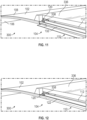
- the housing 338 includes a housing chamber 340. In some aspects, various components and/or portions of components of the lighting system 104 are positionable within the housing chamber 340. In the example of FIGs. 6-12 , the light source 120 and, optionally, the optical diverter 234 are positioned within the housing chamber 340, and the illumination edge 128 of the light guide 122 is further positioned within the housing chamber 340. In various examples, the housing 338 may provide additional support and protection to components of the lighting system 104. The housing 338 may further assist the lighting system 104 provide homogenous and/or uniform lighting to the illumination zone 110 by concealing the direction of the light source emission to the light guide 122 from the light source 120 and/or optical diverter 234.
- the light guide 122 optionally includes a border edge 342 adjacent to illumination edge 128.
- the light guide 122 is shaped such that the border edge 342 forms an infinity edge 344, meaning that the side of the light guide 122 is curved such that the border edge 342 is minimized or concealed when viewed from a plan view.
- forming the infinity edge 344 includes vertically positioning the border edge 342 above the illumination edge 128, although it need not in other examples. In certain cases, the infinity edge 344 may allow for illumination from the cabin furnishing element 300 in an additional direction relative to the panel 102.
- the infinity edge 344 may further provide a more homogenous and/or customizable illumination pattern that minimizes or reduces sharp transition areas between portions of the cabin furnishing element 300 that are illuminated and portions that are not illuminated.
- a cover 346 may be provided on the border edge 342 to further control light distribution in the infinity edge 344. As illustrated in FIG. 9 , in some aspects, a cover 346 may also optionally be provided on other edges of the light guide 122 as desired.
- FIG. 13 illustrates an example of a cabin furnishing system 1300 that includes three of the cabin furnishing elements 300.
- the cabin furnishing system 1300 forms a ceiling of a cabin of an aircraft, and the cabin furnishing elements 300 are ceiling panels.
- the cabin furnishing system 1300 may form various other structures for a cabin, including, but not limited to, sidewall panels, a stowage bin, lavatory panels, or various other suitable structures.
- three cabin furnishing elements are illustrated in FIG. 13 , it will be appreciated that any desired number of cabin furnishing elements may be used with the cabin furnishing system.
- the cabin furnishing system 1300 may include one cabin furnishing element, two cabin furnishing elements, or more than three cabin furnishing elements.
- FIGs. 14 and 15 illustrate an example of a cabin furnishing element 1400 that is substantially similar to the cabin furnishing element 300 except that the cabin furnishing element 1400 includes two covering projections 336.
- the second surface 108 defines at least one insertion opening 1448 that selectively provides access to the lighting recess 112 (and as such the components of the lighting system 104) through the second surface 108.
- FIGs. 16 and 17 illustrate an example of a cabin furnishing element 1600 that is substantially similar to the cabin furnishing element 300 except that the second surface 108 of the cabin furnishing element 1600 further defines the insertion openings 1448 that provide access to the lighting recess 112 (and as such the components of the lighting system 104) through the second surface 108.
- FIGs. 18-28 illustrate an example of a cabin furnishing element 1800 that is substantially similar to the cabin furnishing element 300.
- the cabin furnishing element 1800 includes two housings 338 that are integrally formed with the panel 102, and each housing 338 includes a light source 120.
- the cabin furnishing element 1800 also includes two covering projections 336.
- the second surface 108 of the panel 102 defines two insertion openings 1448 providing access to the lighting recess 112.
- one of the insertion openings 1448 provides access to one of the housings 338 and the other insertion opening 1448 provides access to the other housing 338.
- the light sources 120 are slidably positioned within the housing chambers 340 through the insertion openings 1448, respectively.
- the cabin furnishing element 1800 includes housing covers 1850 that selectively enclose the housings 338 and/or insertion openings 1448 after the light sources 120 are positioned within the housing chambers 340.
- the housing covers 1850 may be removably or permanently attached to the panel 102 and/or to the housings 338, respectively. In the example of FIGs. 18-29 , each housing cover 1850 is attached to the corresponding housing 338.
- the cabin furnishing element 1800 optionally includes a secondary cover 1852 that is selectively positionable on the second surface 108 of the panel 102 to cover the insertion openings 1448 and/or the housing covers 1850 and/or the housings 228.
- a profile of the secondary cover 1852 may be substantially similar to a profile of the covering projections 336, although it need not be in other examples.
- the secondary covers may be removably or permanently secured to the cabin furnishing element 1800.
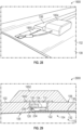
- FIG. 28 illustrates a power supply 1854 that provides power to the light system 104.
- the power supply 1854 should not be considered limiting on the current disclosure.
- the power supply 1854 may provide power to one light source 120 or a plurality of light sources 120.
- FIG. 29 illustrates an example of a cabin furnishing element 2900 that is substantially similar to the cabin furnishing element 1800 except that the housing cover 1850 is attached to both the housing 338 and the panel 102.
Landscapes
- Engineering & Computer Science (AREA)
- Mechanical Engineering (AREA)
- Aviation & Aerospace Engineering (AREA)
- Planar Illumination Modules (AREA)
Description
- This application claims the benefit of
U.S. Provisional Application No. 62/541,818, filed August 7, 2017 - This application relates to lighting systems, and more particularly to lighting systems and devices integrated in a cabin furnishing element, such as a cabin furnishing element for an aircraft cabin.
- Lighting systems are used to provide lighting or illumination in various spaces, including, but not limited to, cabins of various passenger vehicles such as aircraft, trains, buses, or various other passenger vehicles. However, existing lighting systems are often bulky and take up a large installation volume within the cabin, provide insufficient illumination patterns, are difficult to access, and are difficult to combine with other components such as various cabin furnishing elements. Moreover, because lighting systems are separate components and installed separately from cabin furnishing elements, the resulting illumination is not smooth. Therefore, there is a need for improved lighting systems and cabin furnishing elements.
US 9 643536 - The terms "invention," "the invention," "this invention" and "the present invention" used in this patent are intended to refer broadly to all of the subject matter of this patent and the patent claims below. Statements containing these terms should be understood not to limit the subject matter described herein or to limit the meaning or scope of the patent claims below. Embodiments of the invention covered by this patent are defined by the claims below, not this summary. This summary is a high-level overview of various embodiments of the invention and introduces some of the concepts that are further described in the Detailed Description section below. This summary is not intended to identify key or essential features of the claimed subject matter, nor is it intended to be used in isolation to determine the scope of the claimed subject matter. The subject matter should be understood by reference to appropriate portions of the entire specification of this patent, any or all drawings, and each claim.
- A cabin furnishing element according to claim 1 is disclosed.
- Various implementations described in the present disclosure can include additional systems, methods, features, and advantages, which cannot necessarily be expressly disclosed herein but will be apparent to one of ordinary skill in the art upon examination of the following detailed description and accompanying drawings. It is intended that all such systems, methods, features, and advantages be included within the present disclosure and protected by the accompanying claims.
- The features and components of the following figures are illustrated to emphasize the general principles of the present disclosure. Corresponding features and components throughout the figures can be designated by matching reference characters for the sake of consistency and clarity.
-
FIG. 1 is a schematic of a portion of a cabin furnishing element which does not fall within the scope of the claims. -
FIG. 2 is a schematic of a portion of a cabin furnishing element which does not fall within the scope of the claims. -
FIG. 3 is a perspective view of a cabin furnishing element according to aspects of the current disclosure. -
FIG. 4 is another perspective view of the cabin furnishing element ofFIG. 3 . -
FIG. 5 is a perspective view of a panel of the cabin furnishing element ofFIG. 3 . -
FIG. 6 is a perspective view of a portion of a lighting system of the cabin furnishing element ofFIG. 3 . -
FIG. 7 is a side view of a portion of the lighting system of the cabin furnishing element ofFIG. 3 . -
FIG. 8 is a partially exploded assembly view of the lighting system ofFIG. 7 . -
FIG. 9 is a perspective view of a light guide of the lighting system ofFIG. 6 . -
FIG. 10 is a perspective view of a portion of the cabin furnishing element ofFIG. 3 partially assembled. -
FIG. 11 is a perspective view of a portion of the cabin furnishing element ofFIG. 3 partially assembled. -
FIG. 12 is a perspective view of a portion of the cabin furnishing element ofFIG. 3 fully assembled. -
FIG. 12 is a schematic of a portion of a cabin furnishing element according to aspects of the current disclosure. -
FIG. 13 is perspective view of a cabin furnishing system including a plurality of the cabin furnishing elements ofFIG. 3 , which is not part of the claimed subject-matter. -
FIG. 14 is a perspective view of a cabin furnishing element according to aspects of the current disclosure. -
FIG. 15 is a partially exploded assembly view of the cabin furnishing element ofFIG. 14 . -
FIG. 16 is a perspective view of a cabin furnishing element according to aspects of the current disclosure. -
FIG. 17 is a partially exploded assembly view of the cabin furnishing element ofFIG. 16 . -
FIG. 18 is a partially exploded assembly view of a cabin furnishing element according to aspects of the current disclosure. -
FIG. 19 is a perspective view of a portion of the cabin furnishing element ofFIG. 18 . -
FIG. 20 is a perspective view of a portion of the cabin furnishing element ofFIG. 18 . -
FIG. 21 is a perspective view of the cabin furnishing element ofFIG. 18 during assembly. -
FIG. 22 is a perspective view of the cabin furnishing element ofFIG. 18 during assembly. -
FIG. 23 is a perspective view of the cabin furnishing element ofFIG. 18 during assembly. -
FIG. 24 is a perspective view of a light source of a lighting system of the cabin furnishing element ofFIG. 18 . -
FIG. 25 is a side view of the light source ofFIG. 24 . -
FIG. 26 is a perspective view of a portion of the cabin furnishing element ofFIG. 18 during assembly. -
FIG. 27 is a sectional view of a portion of the cabin furnishing element ofFIG. 18 fully assembled. -
FIG. 28 is a perspective view of a portion of the cabin furnishing element ofFIG. 18 . -
FIG. 29 is a sectional view of a portion of a cabin furnishing element according to aspects of the current disclosure. - The subject matter of embodiments of the present invention is described here with specificity to meet statutory requirements, but this description is not necessarily intended to limit the scope of the claims. The claimed subject matter may be embodied in other ways, may include different elements or steps, and may be used in conjunction with other existing or future technologies. This description should not be interpreted as implying any particular order or arrangement among or between various steps or elements except when the order of individual steps or arrangement of elements is explicitly described. Directional references such as "top," "bottom," "left," "right," "front," and "back," among others, are intended to refer to the orientation as illustrated and described in the figure (or figures) to which the components and directions are referencing. References herein to "consisting of" may, in at least some circumstances, encompass "consisting essentially of" or "comprising."
- In some aspects, disclosed is a cabin furnishing element having an integrated lighting system. The cabin furnishing element may be provided as a component of a cabin furnishing system, including, but not limited to, an aircraft cabin furnishing system. In certain aspects, the cabin furnishing element may be a component of various cabin monuments or structures, including, but not limited to, a ceiling panel, a sidewall panel, a stowage bin, a lavatory panel, or various other suitable structures.
- The cabin furnishing element comprises a panel comprising a panel body, the panel body comprising an illumination surface having an illumination zone, and wherein the panel body defines a lighting recess within the panel body and comprising a recess opening corresponding to the illumination zone, wherein it comprises: a housing positioned within the lighting recess, wherein the housing defines a housing chamber; and a lighting system comprising a light source assembly and a light guide retained within the lighting recess defined by the panel body, and in that the light source assembly comprises a light source positioned within the housing chamber, and in that an illumination edge of the light guide is positioned within the housing chamber ; the lighting system being adapted to selectively illuminate a portion of the illumination zone. In some examples, the light source includes a light emitting diode (LED), although various other suitable light sources may be utilized. The light guide is configured to direct a light source emission from the light source to an illumination zone of the panel. The light source and light guide are arranged in the lighting recess such that the light source is adjacent to an edge of the light guide and a light source emission from the light source is directed directly into the light guide. In other aspects, the light source is spaced apart from an edge of the light guide, and the lighting system includes an optical diverter between the light source and the light guide such that the light source emission is directed to the light guide through the optical diverter.
- The cabin furnishing element with the integrated lighting system is compact in size and minimizes or reduces the number of components in the cabin. The cabin furnishing element has a low profile and/or an installation volume that is less than traditional illumination systems, and as such the saved volume may be used for other cabin features and/or used to maximize space for the passenger. In some aspects, the cabin furnishing element provides a smooth and homogenous illumination surface with minimized transition edges, and as such may provide an enhanced appearance and/or ambiance within the cabin. In certain aspects, the cabin furnishing element provides customized illumination. The cabin furnishing element may further provide easy access to components of the light system for service, maintenance, replacement, etc.
-
FIG. 1 illustrates an example of acabin furnishing element 100 which does not fall within the scope of the claims. In some aspects, thecabin furnishing element 100 may be a component of a cabin furnishing system for various areas of a cabin. In various examples, thecabin furnishing element 100 may be a ceiling panel a sidewall panel, a stowage bin, a lavatory panel, or various other suitable structures. Any desired number ofcabin furnishing elements 100 may be utilized in a cabin furnishing system. - As illustrated in
FIG. 1 , thecabin furnishing element 100 includes apanel 102 and alighting system 104. Thepanel 102 may be formed from materials, including, but not limited to aluminum, stainless steel, aramid fibers, polycarbonate, polypropylene, other metallic materials, composite materials, or other similar materials. Thepanel 102 generally includes afirst surface 106 and asecond surface 108 opposite from thefirst surface 106. In some aspects, thefirst surface 106 includes anillumination zone 110 through which a light source emission is directed, and as such thefirst surface 106 is an illumination surface. In such examples, thesecond surface 108 may face various support structures within the cabin when assembled as such may be a support surface. Although illustrated as generally planar surfaces, in various examples, thefirst surface 106 and/or thesecond surface 108 may have various shapes or profiles as desired, and accordingly thepanel 102 may have various shapes or profiles as desired. For example, thefirst surface 106 and/or thesecond surface 108 may be flat or planar, may be arcuate shaped, may be angled, or may have various other profiles as desired. In some aspects, the profile of thefirst surface 106 need not be the same as the profile of the second surface 108 (see, e.g.,FIGs. 4 and5 ). Thepanel 102 may optionally include a decorative layer or covering on at least a portion of thefirst surface 106 and/or thesecond surface 108, although it need not in other examples. - The
panel 102 defines alighting recess 112 within thepanel 102. Thelighting recess 112 is adapted to retain thelighting system 104 within thepanel 102. Thelighting recess 112 has arecess opening 114 that corresponds to theillumination zone 110 such that the light source emission from thelighting system 104 may pass to theillumination zone 110. In some optional aspects, awidth 116 of therecess opening 114 may be less than awidth 118 of thelighting recess 112 such that portions of thelighting recess 112 are covered by portions of thepanel 102, although it need not be in other examples. While asingle lighting recess 112 is illustrated, the number oflight recesses 112 should not be considered limiting on the current disclosure. For example, in other cases, thepanel 102 may define a plurality oflight recesses 112, which may or may not be optically connected. - The
light system 104 includes alight source 120 and alight guide 122. Any number oflight sources 120 and/or light guides 122 may be utilized as desired. Moreover, thelight source 120 and/orlight guide 122 may be arranged in various patterns and/or configurations on thecabin panel 102 as desired. - In some examples, the
light source 120 may include at least one printed circuit board (PCB) 124 populated with one or more light emitting diodes (LEDs) 126 that are configured to emit a light source emission. EachPCB 124 can have wiring for connecting to a power supply, which can be shared between PCBs or each PCB could have its own power supply. TheLEDs 126 may be single-die or multi-die LEDs, DC or AC, can be organic LEDS, and/or may be various other suitable LEDs. White, color, or multicolor LEDs may be used. Moreover, theLEDs 126 mounted on aPCB 124 need not all be the same color; rather, mixtures of LEDs may be used. Furthermore, in some embodiments no PCB is needed; rather, theLEDs 126 are chip-on-board LEDs In other examples, thelight source 120 may be various other suitable devices for emitting a light source emission. - The
light guide 122 is configured to direct the light source emission from thelight source 120. Thelight guide 122 may include various suitable materials for directing the light source emission including, but not limited to, air, various transparent materials, and/or various other suitable materials or combinations of materials. As illustrated inFIG. 1 , thelight guide 122 includes at least oneillumination edge 128 that receives the light source emission from thelight source 120. In some examples, as illustrated inFIG. 1 , theillumination edge 128 is positioned adjacent to the light source 120 (e.g., adjacent to the LEDs 126) such that the light source emission from thelight source 120 is directly into thelight guide 122. In other examples, and as described in detail below with reference toFIG. 2 , theillumination edge 128 may be spaced apart from thelight source 120, and an optical diverter is provided between thelight guide 122 and thelight source 120 such that the light source emission from thelight source 120 is directed to thelight guide 122 through the optical diverter. - As illustrated in
FIG. 1 , thelight source 120 and thelight guide 122 are retained within thelighting recess 112. In certain aspects, thepanel 102 covers a portion of thelight system 104 within thelighting recess 112. In the example ofFIG. 1 , thepanel 102 covers thelight source 120 within thelighting recess 112. - In addition to the
light source 120 and thelight guide 122, thelighting system 104 may include various other optional features. For example, in some cases, thelighting system 104 includes areflector 130 within thelighting recess 112 that aids in distributing the light source emission. Optionally, an optic 132 (such as a lens, diffuser, or other suitable optic) is positioned on or over therecess opening 114. The optic 132 can be made of any nonmetallic material that permits light to exit through the optic 132, including, but not limited to, polymeric materials, silicone and various other suitable materials for light distribution. In certain aspects, the optic 132 includes an optic surface and the optic 132 is positioned such that the optic surface and thefirst surface 106 form a substantially continuous surface. - When the
light system 104 is activated, thelight source 120 provides the light source emission that is directed to thelight guide 122, which provides illumination to theillumination zone 110 of thepanel 102. -
FIG. 2 illustrates an example of acabin furnishing element 200, which does not fall within the scope of the claims, that is substantially similar to thecabin furnishing element 100 except that the cabin furnishing element includes twolight sources 120, and each of thelight sources 120 is spaced apart from the corresponding illumination edges 128 of thelight guide 122. In such examples, anoptical diverter 234 may be provided between thelight source 120 and the correspondingillumination edge 128 such that the light source emission from thelight source 120 is directed to thelight guide 122 through theoptical diverter 234. Theoptical diverter 234 may be various suitable devices for directing the light source emission from thelight source 120 to thelight guide 122 including, but not limited to, a prism, optical cable, or various other suitable devices. In certain examples, theoptical diverter 234 may divert the light source emission in the needed direction and at various suitable angles. As one non-limiting example, theoptical diverter 234 may divert the light source emission at about 90°, at a non-zero angle, at a square angle, a zero angle, or various other angles as desired. In some aspects, theoptical diverter 234 may allow for thecabin furnishing element 200 to be more adaptable and/or customizable as desired because thelight source 120 can be spaced apart from thelight guide 122. -
FIGs. 3-12 illustrate an example of acabin furnishing element 300 that is substantially similar to thecabin furnishing element 200. Compared to thecabin furnishing element 200, thepanel 102 of thecabin furnishing element 300 is generally arcuate shaped. As best illustrated inFIGs. 3 and 4 , the profile of thefirst surface 106 is different from the profile of thesecond surface 108 in that thesecond surface 108 includes a coveringprojection 336. In some examples, the coveringprojection 336 may be integrally or monolithically formed with thepanel 102. In other examples, the coveringprojection 336 may be a component that is attached to thepanel 102 after thepanel 102 is formed. In some aspects, the coveringprojection 336 may be permanently attached to thepanel 102 or may be removably attached to thepanel 102 through various suitable mechanisms including, but not limited to screws, bolts, rivets, pins, hooks, adhesives, and/or other mechanical or chemical fasteners. - As illustrated in
FIGs. 6-12 , in some aspects, thecabin furnishing element 300 includes ahousing 338 that is positionable within thelighting recess 112. Thehousing 338 may be integrally formed with thepanel 102 or may be insertable into thelighting recess 112 after thepanel 102 has been formed. Thehousing 338 may be formed from a material that is the same as or different from the material used to form thepanel 102. - The
housing 338 includes ahousing chamber 340. In some aspects, various components and/or portions of components of thelighting system 104 are positionable within thehousing chamber 340. In the example ofFIGs. 6-12 , thelight source 120 and, optionally, theoptical diverter 234 are positioned within thehousing chamber 340, and theillumination edge 128 of thelight guide 122 is further positioned within thehousing chamber 340. In various examples, thehousing 338 may provide additional support and protection to components of thelighting system 104. Thehousing 338 may further assist thelighting system 104 provide homogenous and/or uniform lighting to theillumination zone 110 by concealing the direction of the light source emission to thelight guide 122 from thelight source 120 and/oroptical diverter 234. - In some examples, as best illustrated in
FIGs. 8 and 9 , thelight guide 122 optionally includes aborder edge 342 adjacent toillumination edge 128. In some aspects, thelight guide 122 is shaped such that theborder edge 342 forms aninfinity edge 344, meaning that the side of thelight guide 122 is curved such that theborder edge 342 is minimized or concealed when viewed from a plan view. In some examples, forming theinfinity edge 344 includes vertically positioning theborder edge 342 above theillumination edge 128, although it need not in other examples. In certain cases, theinfinity edge 344 may allow for illumination from thecabin furnishing element 300 in an additional direction relative to thepanel 102. Theinfinity edge 344 may further provide a more homogenous and/or customizable illumination pattern that minimizes or reduces sharp transition areas between portions of thecabin furnishing element 300 that are illuminated and portions that are not illuminated. Optionally, acover 346 may be provided on theborder edge 342 to further control light distribution in theinfinity edge 344. As illustrated inFIG. 9 , in some aspects, acover 346 may also optionally be provided on other edges of thelight guide 122 as desired. -
FIG. 13 illustrates an example of acabin furnishing system 1300 that includes three of thecabin furnishing elements 300. In other examples, various other types of cabin furnishing elements and/or combinations of types of cabin furnishing elements may be utilized. In the example ofFIG. 13 , thecabin furnishing system 1300 forms a ceiling of a cabin of an aircraft, and thecabin furnishing elements 300 are ceiling panels. However, in other examples, thecabin furnishing system 1300 may form various other structures for a cabin, including, but not limited to, sidewall panels, a stowage bin, lavatory panels, or various other suitable structures. In addition, while three cabin furnishing elements are illustrated inFIG. 13 , it will be appreciated that any desired number of cabin furnishing elements may be used with the cabin furnishing system. For example, thecabin furnishing system 1300 may include one cabin furnishing element, two cabin furnishing elements, or more than three cabin furnishing elements. -
FIGs. 14 and 15 illustrate an example of acabin furnishing element 1400 that is substantially similar to thecabin furnishing element 300 except that thecabin furnishing element 1400 includes two coveringprojections 336. In thecabin furnishing element 1400, thesecond surface 108 defines at least oneinsertion opening 1448 that selectively provides access to the lighting recess 112 (and as such the components of the lighting system 104) through thesecond surface 108. -
FIGs. 16 and 17 illustrate an example of acabin furnishing element 1600 that is substantially similar to thecabin furnishing element 300 except that thesecond surface 108 of thecabin furnishing element 1600 further defines theinsertion openings 1448 that provide access to the lighting recess 112 (and as such the components of the lighting system 104) through thesecond surface 108. -
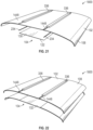
FIGs. 18-28 illustrate an example of acabin furnishing element 1800 that is substantially similar to thecabin furnishing element 300. Compared to thecabin furnishing element 300, thecabin furnishing element 1800 includes twohousings 338 that are integrally formed with thepanel 102, and eachhousing 338 includes alight source 120. Thecabin furnishing element 1800 also includes two coveringprojections 336. In addition, thesecond surface 108 of thepanel 102 defines twoinsertion openings 1448 providing access to thelighting recess 112. In the example ofFIGs. 18-28 , one of theinsertion openings 1448 provides access to one of thehousings 338 and theother insertion opening 1448 provides access to theother housing 338. In some aspects, and as illustrated inFIG. 23 , during assembly of thecabin furnishing element 1800, thelight sources 120 are slidably positioned within thehousing chambers 340 through theinsertion openings 1448, respectively. - Optionally, the
cabin furnishing element 1800 includeshousing covers 1850 that selectively enclose thehousings 338 and/orinsertion openings 1448 after thelight sources 120 are positioned within thehousing chambers 340. The housing covers 1850 may be removably or permanently attached to thepanel 102 and/or to thehousings 338, respectively. In the example ofFIGs. 18-29 , eachhousing cover 1850 is attached to thecorresponding housing 338. - As illustrated in
FIG. 26 , thecabin furnishing element 1800 optionally includes asecondary cover 1852 that is selectively positionable on thesecond surface 108 of thepanel 102 to cover theinsertion openings 1448 and/or the housing covers 1850 and/or the housings 228. In some examples, a profile of thesecondary cover 1852 may be substantially similar to a profile of the coveringprojections 336, although it need not be in other examples. The secondary covers may be removably or permanently secured to thecabin furnishing element 1800. -
FIG. 28 illustrates apower supply 1854 that provides power to thelight system 104. Thepower supply 1854 should not be considered limiting on the current disclosure. In various aspects, thepower supply 1854 may provide power to onelight source 120 or a plurality oflight sources 120. -
FIG. 29 illustrates an example of acabin furnishing element 2900 that is substantially similar to thecabin furnishing element 1800 except that thehousing cover 1850 is attached to both thehousing 338 and thepanel 102. - The above-described aspects are merely possible examples of implementations, merely set forth for a clear understanding of the principles of the present disclosure. The modifications and variations are intended to be included herein within the scope of the present disclosure, and all possible claims to individual aspects or combinations of elements or steps are intended to be supported by the present disclosure and by the appended claims.
Claims (8)
- A cabin furnishing element (100, 200, 300, 1400, 1600, 1800, 2900) comprising:
a panel (102) comprising a panel (102) body, the panel (102) body comprising an illumination surface having an illumination zone (110), and wherein the panel (102) body defines a lighting recess (112) within the panel (102) body and comprising a recess opening (114) corresponding to the illumination zone (110), characterized in that it comprises:a housing (338) positioned within the lighting recess (112), wherein the housing (338) defines a housing chamber (340); anda lighting system (104) comprising a light source (120) assembly and a light guide (122) retained within the lighting recess (112) defined by the panel (102) body, wherein the light source (120) assembly comprises a light source (120) positioned within the housing chamber, and in that an illumination edge (128) of the light guide (122) is positioned within the housing chamber (340); the lighting system (104) being adapted to selectively illuminate a portion of the illumination zone (110). - The cabin furnishing element (100, 200, 300, 1400, 1600, 1800, 2900) of claim 1, wherein the panel (102) comprises at least one of a ceiling panel (102), a sidewall panel (102), a stowage bin panel (102), or a lavatory module panel (102).
- The cabin furnishing element (100, 200, 300, 1400, 1600, 1800, 2900) of claim 1, wherein the light source (120) is spaced apart from the illumination edge (128) of the light guide (122) in the housing chamber (340), and wherein the lighting system (104) further comprises an optical diverter (234) between the light source (120) assembly and the illumination edge (128) of the light guide (122) such that a light source emission from the light source (120) assembly is directed into the light guide (122) through the optical diverter (234).
- The cabin furnishing element (100, 200, 300, 1400, 1600, 1800, 2900) of claim 3, wherein the optical diverter (234) is configured to divert the light source emission at a non-zero angle.
- The cabin furnishing element (100, 200, 300, 1400, 1600, 1800, 2900) of claim 1, wherein the light source (120) assembly comprises:a light source housing (338) integrally formed with the panel (102) body and defining a housing chamber (340); andat least one light emitting diode supported within the housing chamber.
- The cabin furnishing element (100, 200, 300, 1400, 1600, 1800, 2900) of claim 1, wherein the light guide (122) further comprises a guide surface having the illumination edge (128) and a border edge (342) adjacent to the illumination edge (128) wherein the illumination edge (128) is adapted to receive a light source emission from the light source (120)assembly, and wherein the guide surface is shaped such that the illumination edge (128) and the border edge (342) are non-coplanar and the border edge (342) is vertically above a non-edge portion of the illumination surface.
- The cabin furnishing element (100, 200, 300, 1400, 1600, 1800, 2900) of claim 1, wherein
the panel (102) body comprises a first surface (106) and a second surface opposite from the first surface (106), wherein a portion of the first surface (106) comprises the illumination zone (110). - The cabin furnishing element (100, 200, 300, 1400, 1600, 1800, 2900) of claim 7, wherein the lighting system (104) further comprises a diffuser positioned such that a diffuser surface is substantially continuous with the first surface (106).
Applications Claiming Priority (2)
| Application Number | Priority Date | Filing Date | Title |
|---|---|---|---|
| US201762541818P | 2017-08-07 | 2017-08-07 | |
| PCT/IB2018/055872 WO2019030634A1 (en) | 2017-08-07 | 2018-08-03 | Area light integrated in a cabin furnishing element |
Publications (2)
| Publication Number | Publication Date |
|---|---|
| EP3665080A1 EP3665080A1 (en) | 2020-06-17 |
| EP3665080B1 true EP3665080B1 (en) | 2023-11-22 |
Family
ID=63449510
Family Applications (1)
| Application Number | Title | Priority Date | Filing Date |
|---|---|---|---|
| EP18762633.8A Active EP3665080B1 (en) | 2017-08-07 | 2018-08-03 | Area light integrated in a cabin furnishing element |
Country Status (5)
| Country | Link |
|---|---|
| US (2) | US11104271B2 (en) |
| EP (1) | EP3665080B1 (en) |
| CN (1) | CN111741898A (en) |
| HU (1) | HUE067814T2 (en) |
| WO (1) | WO2019030634A1 (en) |
Family Cites Families (22)
| Publication number | Priority date | Publication date | Assignee | Title |
|---|---|---|---|---|
| US6712481B2 (en) * | 1995-06-27 | 2004-03-30 | Solid State Opto Limited | Light emitting panel assemblies |
| DE502005004788D1 (en) | 2004-10-20 | 2008-09-04 | Airbus Gmbh | Lighting unit for aircraft |
| EP1932032A1 (en) * | 2005-09-19 | 2008-06-18 | Koninklijke Philips Electronics N.V. | Improved waveguide and lighting device |
| US7270452B2 (en) * | 2005-10-18 | 2007-09-18 | Yu Lin Enterprise Co., Ltd | Light emitting handle for vehicle |
| US20070139941A1 (en) | 2005-11-16 | 2007-06-21 | Bryan Eric A | Ceiling illumination for aircraft interiors |
| DE102006007285A1 (en) * | 2006-02-16 | 2007-08-30 | Airbus Deutschland Gmbh | Visualization system in an airplane |
| CN101765525A (en) * | 2007-06-07 | 2010-06-30 | 约翰逊控制技术公司 | Luminous components for vehicles |
| KR100966619B1 (en) * | 2008-03-19 | 2010-06-29 | 윤제숭 | LED lighting device |
| FR2955539B1 (en) * | 2010-01-26 | 2016-03-25 | Saint Gobain | LUMINOUS VEHICLE GLAZING, MANUFACTURING |
| DE102010036795A1 (en) * | 2010-08-02 | 2012-02-02 | International Automotive Components Group Gmbh | Covering device for a motor vehicle with integrated lighting system |
| KR101827712B1 (en) * | 2011-05-27 | 2018-02-09 | 엘지이노텍 주식회사 | Lighting module |
| JP6134484B2 (en) * | 2012-06-29 | 2017-05-24 | 株式会社小糸製作所 | Vehicle rear panel |
| TWI499841B (en) * | 2012-10-26 | 2015-09-11 | Young Lighting Technology Inc | Illumination apparatus |
| KR101340053B1 (en) * | 2013-02-14 | 2013-12-10 | (주)솔라루체 | Structure of face illumination device for preventing light source loss |
| DE102013110839A1 (en) * | 2013-10-01 | 2015-04-02 | Hella Kgaa Hueck & Co. | Lighting device for vehicles |
| JP5907143B2 (en) * | 2013-10-23 | 2016-04-20 | 豊田合成株式会社 | Lighting device |
| DE102014202774B4 (en) | 2014-02-14 | 2021-02-18 | Airbus Operations Gmbh | Ceiling lining element for an interior lining arrangement of an aircraft cabin |
| US20150251594A1 (en) * | 2014-03-07 | 2015-09-10 | Idd Aerospace Corporation | Aircraft cabin light system |
| DE102014011170A1 (en) * | 2014-07-29 | 2016-02-04 | Diehl Aircabin Gmbh | A light-emitting composite assembly and method of making the composite light-emitting assembly |
| JP6424758B2 (en) * | 2015-07-23 | 2018-11-21 | 豊田合成株式会社 | Decorative lighting device |
| DE102016001629A1 (en) * | 2016-02-15 | 2017-08-17 | Webasto SE | Cover of a vehicle roof |
| KR101991082B1 (en) * | 2016-12-28 | 2019-09-30 | 코오롱글로텍주식회사 | Ambient lighting apparatus for vehicle and method for manufacturing the same |
-
2018
- 2018-08-03 US US16/637,438 patent/US11104271B2/en active Active
- 2018-08-03 CN CN201880062893.9A patent/CN111741898A/en active Pending
- 2018-08-03 EP EP18762633.8A patent/EP3665080B1/en active Active
- 2018-08-03 WO PCT/IB2018/055872 patent/WO2019030634A1/en not_active Ceased
- 2018-08-03 HU HUE18762633A patent/HUE067814T2/en unknown
-
2021
- 2021-08-13 US US17/401,586 patent/US11618375B2/en active Active
Also Published As
| Publication number | Publication date |
|---|---|
| US11618375B2 (en) | 2023-04-04 |
| EP3665080A1 (en) | 2020-06-17 |
| WO2019030634A1 (en) | 2019-02-14 |
| HUE067814T2 (en) | 2024-11-28 |
| CN111741898A (en) | 2020-10-02 |
| US20210370825A1 (en) | 2021-12-02 |
| US20200223356A1 (en) | 2020-07-16 |
| US11104271B2 (en) | 2021-08-31 |
Similar Documents
| Publication | Publication Date | Title |
|---|---|---|
| US7566154B2 (en) | Aircraft LED dome light having rotatably releasable housing mounted within mounting flange | |
| US7540639B2 (en) | Cross bin illumination system | |
| EP2581898B1 (en) | Edge-Lit Luminaire | |
| EP3002505B1 (en) | Array-based lighting systems and methods of manufacturing | |
| US9169017B2 (en) | Aircraft interior lighting system using structured micro lens arrays | |
| US7717593B2 (en) | Device for improved illumination efficiency | |
| US20150251594A1 (en) | Aircraft cabin light system | |
| CA2615448C (en) | Illumination in the area of aircraft cabins | |
| US20090116257A1 (en) | Low profile lightbar with IR illumination | |
| EP2586709B1 (en) | Modular led based aircraft rear position light | |
| WO2011103535A2 (en) | Thin light emitting modular panel system | |
| US20140036503A1 (en) | Drop ceiling lighting techniques | |
| US10279910B2 (en) | Lighting systems | |
| EP3305659B1 (en) | Methods and devices for light distribution in an aircraft, and aircraft including such devices | |
| JP2009143409A (en) | Vehicle interior lighting device | |
| WO2017059431A1 (en) | Supplemental lighting element | |
| US7370995B2 (en) | Console and light assembly | |
| JP2014097850A (en) | Luminaire in elevator car | |
| US20130016517A1 (en) | Aircraft Washlight System | |
| US11618375B2 (en) | Area light integrated in a cabin furnishing element | |
| KR102067578B1 (en) | Illuminating wall | |
| EP2125518B1 (en) | Illumination device for an aircraft | |
| US10876726B2 (en) | Aircraft mirror assembly | |
| WO2014011806A2 (en) | An aircraft washlight system | |
| KR20170018729A (en) | Light source control apparatus of ship |
Legal Events
| Date | Code | Title | Description |
|---|---|---|---|
| STAA | Information on the status of an ep patent application or granted ep patent |
Free format text: STATUS: UNKNOWN |
|
| STAA | Information on the status of an ep patent application or granted ep patent |
Free format text: STATUS: THE INTERNATIONAL PUBLICATION HAS BEEN MADE |
|
| PUAI | Public reference made under article 153(3) epc to a published international application that has entered the european phase |
Free format text: ORIGINAL CODE: 0009012 |
|
| STAA | Information on the status of an ep patent application or granted ep patent |
Free format text: STATUS: REQUEST FOR EXAMINATION WAS MADE |
|
| 17P | Request for examination filed |
Effective date: 20200228 |
|
| AK | Designated contracting states |
Kind code of ref document: A1 Designated state(s): AL AT BE BG CH CY CZ DE DK EE ES FI FR GB GR HR HU IE IS IT LI LT LU LV MC MK MT NL NO PL PT RO RS SE SI SK SM TR |
|
| AX | Request for extension of the european patent |
Extension state: BA ME |
|
| DAV | Request for validation of the european patent (deleted) | ||
| DAX | Request for extension of the european patent (deleted) | ||
| STAA | Information on the status of an ep patent application or granted ep patent |
Free format text: STATUS: EXAMINATION IS IN PROGRESS |
|
| 17Q | First examination report despatched |
Effective date: 20220209 |
|
| GRAP | Despatch of communication of intention to grant a patent |
Free format text: ORIGINAL CODE: EPIDOSNIGR1 |
|
| STAA | Information on the status of an ep patent application or granted ep patent |
Free format text: STATUS: GRANT OF PATENT IS INTENDED |
|
| INTG | Intention to grant announced |
Effective date: 20230614 |
|
| GRAS | Grant fee paid |
Free format text: ORIGINAL CODE: EPIDOSNIGR3 |
|
| GRAA | (expected) grant |
Free format text: ORIGINAL CODE: 0009210 |
|
| STAA | Information on the status of an ep patent application or granted ep patent |
Free format text: STATUS: THE PATENT HAS BEEN GRANTED |
|
| AK | Designated contracting states |
Kind code of ref document: B1 Designated state(s): AL AT BE BG CH CY CZ DE DK EE ES FI FR GB GR HR HU IE IS IT LI LT LU LV MC MK MT NL NO PL PT RO RS SE SI SK SM TR |
|
| REG | Reference to a national code |
Ref country code: GB Ref legal event code: FG4D |
|
| REG | Reference to a national code |
Ref country code: CH Ref legal event code: EP |
|
| REG | Reference to a national code |
Ref country code: DE Ref legal event code: R096 Ref document number: 602018061462 Country of ref document: DE |
|
| REG | Reference to a national code |
Ref country code: IE Ref legal event code: FG4D |
|
| REG | Reference to a national code |
Ref country code: LT Ref legal event code: MG9D |
|
| REG | Reference to a national code |
Ref country code: NL Ref legal event code: MP Effective date: 20231122 |
|
| PG25 | Lapsed in a contracting state [announced via postgrant information from national office to epo] |
Ref country code: GR Free format text: LAPSE BECAUSE OF FAILURE TO SUBMIT A TRANSLATION OF THE DESCRIPTION OR TO PAY THE FEE WITHIN THE PRESCRIBED TIME-LIMIT Effective date: 20240223 |
|
| PG25 | Lapsed in a contracting state [announced via postgrant information from national office to epo] |
Ref country code: IS Free format text: LAPSE BECAUSE OF FAILURE TO SUBMIT A TRANSLATION OF THE DESCRIPTION OR TO PAY THE FEE WITHIN THE PRESCRIBED TIME-LIMIT Effective date: 20240322 |
|
| PG25 | Lapsed in a contracting state [announced via postgrant information from national office to epo] |
Ref country code: LT Free format text: LAPSE BECAUSE OF FAILURE TO SUBMIT A TRANSLATION OF THE DESCRIPTION OR TO PAY THE FEE WITHIN THE PRESCRIBED TIME-LIMIT Effective date: 20231122 |
|
| PG25 | Lapsed in a contracting state [announced via postgrant information from national office to epo] |
Ref country code: NL Free format text: LAPSE BECAUSE OF FAILURE TO SUBMIT A TRANSLATION OF THE DESCRIPTION OR TO PAY THE FEE WITHIN THE PRESCRIBED TIME-LIMIT Effective date: 20231122 |
|
| PG25 | Lapsed in a contracting state [announced via postgrant information from national office to epo] |
Ref country code: ES Free format text: LAPSE BECAUSE OF FAILURE TO SUBMIT A TRANSLATION OF THE DESCRIPTION OR TO PAY THE FEE WITHIN THE PRESCRIBED TIME-LIMIT Effective date: 20231122 |
|
| PG25 | Lapsed in a contracting state [announced via postgrant information from national office to epo] |
Ref country code: NL Free format text: LAPSE BECAUSE OF FAILURE TO SUBMIT A TRANSLATION OF THE DESCRIPTION OR TO PAY THE FEE WITHIN THE PRESCRIBED TIME-LIMIT Effective date: 20231122 Ref country code: LT Free format text: LAPSE BECAUSE OF FAILURE TO SUBMIT A TRANSLATION OF THE DESCRIPTION OR TO PAY THE FEE WITHIN THE PRESCRIBED TIME-LIMIT Effective date: 20231122 Ref country code: IS Free format text: LAPSE BECAUSE OF FAILURE TO SUBMIT A TRANSLATION OF THE DESCRIPTION OR TO PAY THE FEE WITHIN THE PRESCRIBED TIME-LIMIT Effective date: 20240322 Ref country code: GR Free format text: LAPSE BECAUSE OF FAILURE TO SUBMIT A TRANSLATION OF THE DESCRIPTION OR TO PAY THE FEE WITHIN THE PRESCRIBED TIME-LIMIT Effective date: 20240223 Ref country code: ES Free format text: LAPSE BECAUSE OF FAILURE TO SUBMIT A TRANSLATION OF THE DESCRIPTION OR TO PAY THE FEE WITHIN THE PRESCRIBED TIME-LIMIT Effective date: 20231122 Ref country code: BG Free format text: LAPSE BECAUSE OF FAILURE TO SUBMIT A TRANSLATION OF THE DESCRIPTION OR TO PAY THE FEE WITHIN THE PRESCRIBED TIME-LIMIT Effective date: 20240222 Ref country code: PT Free format text: LAPSE BECAUSE OF FAILURE TO SUBMIT A TRANSLATION OF THE DESCRIPTION OR TO PAY THE FEE WITHIN THE PRESCRIBED TIME-LIMIT Effective date: 20240322 |
|
| PG25 | Lapsed in a contracting state [announced via postgrant information from national office to epo] |
Ref country code: SE Free format text: LAPSE BECAUSE OF FAILURE TO SUBMIT A TRANSLATION OF THE DESCRIPTION OR TO PAY THE FEE WITHIN THE PRESCRIBED TIME-LIMIT Effective date: 20231122 Ref country code: RS Free format text: LAPSE BECAUSE OF FAILURE TO SUBMIT A TRANSLATION OF THE DESCRIPTION OR TO PAY THE FEE WITHIN THE PRESCRIBED TIME-LIMIT Effective date: 20231122 Ref country code: PL Free format text: LAPSE BECAUSE OF FAILURE TO SUBMIT A TRANSLATION OF THE DESCRIPTION OR TO PAY THE FEE WITHIN THE PRESCRIBED TIME-LIMIT Effective date: 20231122 Ref country code: NO Free format text: LAPSE BECAUSE OF FAILURE TO SUBMIT A TRANSLATION OF THE DESCRIPTION OR TO PAY THE FEE WITHIN THE PRESCRIBED TIME-LIMIT Effective date: 20240222 Ref country code: LV Free format text: LAPSE BECAUSE OF FAILURE TO SUBMIT A TRANSLATION OF THE DESCRIPTION OR TO PAY THE FEE WITHIN THE PRESCRIBED TIME-LIMIT Effective date: 20231122 Ref country code: HR Free format text: LAPSE BECAUSE OF FAILURE TO SUBMIT A TRANSLATION OF THE DESCRIPTION OR TO PAY THE FEE WITHIN THE PRESCRIBED TIME-LIMIT Effective date: 20231122 |
|
| REG | Reference to a national code |
Ref country code: AT Ref legal event code: UEP Ref document number: 1633613 Country of ref document: AT Kind code of ref document: T Effective date: 20231122 |
|
| PG25 | Lapsed in a contracting state [announced via postgrant information from national office to epo] |
Ref country code: DK Free format text: LAPSE BECAUSE OF FAILURE TO SUBMIT A TRANSLATION OF THE DESCRIPTION OR TO PAY THE FEE WITHIN THE PRESCRIBED TIME-LIMIT Effective date: 20231122 |
|
| PG25 | Lapsed in a contracting state [announced via postgrant information from national office to epo] |
Ref country code: CZ Free format text: LAPSE BECAUSE OF FAILURE TO SUBMIT A TRANSLATION OF THE DESCRIPTION OR TO PAY THE FEE WITHIN THE PRESCRIBED TIME-LIMIT Effective date: 20231122 |
|
| PG25 | Lapsed in a contracting state [announced via postgrant information from national office to epo] |
Ref country code: SK Free format text: LAPSE BECAUSE OF FAILURE TO SUBMIT A TRANSLATION OF THE DESCRIPTION OR TO PAY THE FEE WITHIN THE PRESCRIBED TIME-LIMIT Effective date: 20231122 |
|
| PG25 | Lapsed in a contracting state [announced via postgrant information from national office to epo] |
Ref country code: SM Free format text: LAPSE BECAUSE OF FAILURE TO SUBMIT A TRANSLATION OF THE DESCRIPTION OR TO PAY THE FEE WITHIN THE PRESCRIBED TIME-LIMIT Effective date: 20231122 Ref country code: SK Free format text: LAPSE BECAUSE OF FAILURE TO SUBMIT A TRANSLATION OF THE DESCRIPTION OR TO PAY THE FEE WITHIN THE PRESCRIBED TIME-LIMIT Effective date: 20231122 Ref country code: RO Free format text: LAPSE BECAUSE OF FAILURE TO SUBMIT A TRANSLATION OF THE DESCRIPTION OR TO PAY THE FEE WITHIN THE PRESCRIBED TIME-LIMIT Effective date: 20231122 Ref country code: IT Free format text: LAPSE BECAUSE OF FAILURE TO SUBMIT A TRANSLATION OF THE DESCRIPTION OR TO PAY THE FEE WITHIN THE PRESCRIBED TIME-LIMIT Effective date: 20231122 Ref country code: EE Free format text: LAPSE BECAUSE OF FAILURE TO SUBMIT A TRANSLATION OF THE DESCRIPTION OR TO PAY THE FEE WITHIN THE PRESCRIBED TIME-LIMIT Effective date: 20231122 Ref country code: DK Free format text: LAPSE BECAUSE OF FAILURE TO SUBMIT A TRANSLATION OF THE DESCRIPTION OR TO PAY THE FEE WITHIN THE PRESCRIBED TIME-LIMIT Effective date: 20231122 Ref country code: CZ Free format text: LAPSE BECAUSE OF FAILURE TO SUBMIT A TRANSLATION OF THE DESCRIPTION OR TO PAY THE FEE WITHIN THE PRESCRIBED TIME-LIMIT Effective date: 20231122 |
|
| REG | Reference to a national code |
Ref country code: DE Ref legal event code: R097 Ref document number: 602018061462 Country of ref document: DE |
|
| PLBE | No opposition filed within time limit |
Free format text: ORIGINAL CODE: 0009261 |
|
| STAA | Information on the status of an ep patent application or granted ep patent |
Free format text: STATUS: NO OPPOSITION FILED WITHIN TIME LIMIT |
|
| PG25 | Lapsed in a contracting state [announced via postgrant information from national office to epo] |
Ref country code: SI Free format text: LAPSE BECAUSE OF FAILURE TO SUBMIT A TRANSLATION OF THE DESCRIPTION OR TO PAY THE FEE WITHIN THE PRESCRIBED TIME-LIMIT Effective date: 20231122 |
|
| 26N | No opposition filed |
Effective date: 20240823 |
|
| PG25 | Lapsed in a contracting state [announced via postgrant information from national office to epo] |
Ref country code: SI Free format text: LAPSE BECAUSE OF FAILURE TO SUBMIT A TRANSLATION OF THE DESCRIPTION OR TO PAY THE FEE WITHIN THE PRESCRIBED TIME-LIMIT Effective date: 20231122 |
|
| REG | Reference to a national code |
Ref country code: HU Ref legal event code: AG4A Ref document number: E067814 Country of ref document: HU |
|
| REG | Reference to a national code |
Ref country code: CH Ref legal event code: PL |
|
| PG25 | Lapsed in a contracting state [announced via postgrant information from national office to epo] |
Ref country code: LU Free format text: LAPSE BECAUSE OF NON-PAYMENT OF DUE FEES Effective date: 20240803 |
|
| PG25 | Lapsed in a contracting state [announced via postgrant information from national office to epo] |
Ref country code: MC Free format text: LAPSE BECAUSE OF FAILURE TO SUBMIT A TRANSLATION OF THE DESCRIPTION OR TO PAY THE FEE WITHIN THE PRESCRIBED TIME-LIMIT Effective date: 20231122 Ref country code: CH Free format text: LAPSE BECAUSE OF NON-PAYMENT OF DUE FEES Effective date: 20240831 |
|
| REG | Reference to a national code |
Ref country code: BE Ref legal event code: MM Effective date: 20240831 |
|
| PG25 | Lapsed in a contracting state [announced via postgrant information from national office to epo] |
Ref country code: BE Free format text: LAPSE BECAUSE OF NON-PAYMENT OF DUE FEES Effective date: 20240831 |
|
| PG25 | Lapsed in a contracting state [announced via postgrant information from national office to epo] |
Ref country code: IE Free format text: LAPSE BECAUSE OF NON-PAYMENT OF DUE FEES Effective date: 20240803 |
|
| PGFP | Annual fee paid to national office [announced via postgrant information from national office to epo] |
Ref country code: HU Payment date: 20250730 Year of fee payment: 8 |
|
| PG25 | Lapsed in a contracting state [announced via postgrant information from national office to epo] |
Ref country code: FI Free format text: LAPSE BECAUSE OF FAILURE TO SUBMIT A TRANSLATION OF THE DESCRIPTION OR TO PAY THE FEE WITHIN THE PRESCRIBED TIME-LIMIT Effective date: 20231122 |
|
| PGFP | Annual fee paid to national office [announced via postgrant information from national office to epo] |
Ref country code: DE Payment date: 20250819 Year of fee payment: 8 |
|
| PGFP | Annual fee paid to national office [announced via postgrant information from national office to epo] |
Ref country code: TR Payment date: 20250729 Year of fee payment: 8 |
|
| PGFP | Annual fee paid to national office [announced via postgrant information from national office to epo] |
Ref country code: GB Payment date: 20250825 Year of fee payment: 8 |
|
| PGFP | Annual fee paid to national office [announced via postgrant information from national office to epo] |
Ref country code: FR Payment date: 20250821 Year of fee payment: 8 Ref country code: AT Payment date: 20250819 Year of fee payment: 8 |
|
| PG25 | Lapsed in a contracting state [announced via postgrant information from national office to epo] |
Ref country code: CY Free format text: LAPSE BECAUSE OF FAILURE TO SUBMIT A TRANSLATION OF THE DESCRIPTION OR TO PAY THE FEE WITHIN THE PRESCRIBED TIME-LIMIT; INVALID AB INITIO Effective date: 20180803 |