EP3664596B1 - Presse à balles pouvant être reliée à un tracteur pour créer des balles rondes et procédé de production de balles rondes - Google Patents
Presse à balles pouvant être reliée à un tracteur pour créer des balles rondes et procédé de production de balles rondes Download PDFInfo
- Publication number
- EP3664596B1 EP3664596B1 EP18762154.5A EP18762154A EP3664596B1 EP 3664596 B1 EP3664596 B1 EP 3664596B1 EP 18762154 A EP18762154 A EP 18762154A EP 3664596 B1 EP3664596 B1 EP 3664596B1
- Authority
- EP
- European Patent Office
- Prior art keywords
- conduit
- chamber
- pressure
- tailgate
- baler
- Prior art date
- Legal status (The legal status is an assumption and is not a legal conclusion. Google has not performed a legal analysis and makes no representation as to the accuracy of the status listed.)
- Active
Links
Images

Classifications
-
- F—MECHANICAL ENGINEERING; LIGHTING; HEATING; WEAPONS; BLASTING
- F15—FLUID-PRESSURE ACTUATORS; HYDRAULICS OR PNEUMATICS IN GENERAL
- F15B—SYSTEMS ACTING BY MEANS OF FLUIDS IN GENERAL; FLUID-PRESSURE ACTUATORS, e.g. SERVOMOTORS; DETAILS OF FLUID-PRESSURE SYSTEMS, NOT OTHERWISE PROVIDED FOR
- F15B13/00—Details of servomotor systems ; Valves for servomotor systems
- F15B13/02—Fluid distribution or supply devices characterised by their adaptation to the control of servomotors
- F15B13/04—Fluid distribution or supply devices characterised by their adaptation to the control of servomotors for use with a single servomotor
- F15B13/0401—Valve members; Fluid interconnections therefor
-
- A—HUMAN NECESSITIES
- A01—AGRICULTURE; FORESTRY; ANIMAL HUSBANDRY; HUNTING; TRAPPING; FISHING
- A01F—PROCESSING OF HARVESTED PRODUCE; HAY OR STRAW PRESSES; DEVICES FOR STORING AGRICULTURAL OR HORTICULTURAL PRODUCE
- A01F15/00—Baling presses for straw, hay or the like
- A01F15/08—Details
- A01F15/0825—Regulating or controlling density or shape of the bale
- A01F15/0833—Regulating or controlling density or shape of the bale for round balers
-
- A—HUMAN NECESSITIES
- A01—AGRICULTURE; FORESTRY; ANIMAL HUSBANDRY; HUNTING; TRAPPING; FISHING
- A01F—PROCESSING OF HARVESTED PRODUCE; HAY OR STRAW PRESSES; DEVICES FOR STORING AGRICULTURAL OR HORTICULTURAL PRODUCE
- A01F15/00—Baling presses for straw, hay or the like
- A01F15/07—Rotobalers, i.e. machines for forming cylindrical bales by winding and pressing
-
- A—HUMAN NECESSITIES
- A01—AGRICULTURE; FORESTRY; ANIMAL HUSBANDRY; HUNTING; TRAPPING; FISHING
- A01F—PROCESSING OF HARVESTED PRODUCE; HAY OR STRAW PRESSES; DEVICES FOR STORING AGRICULTURAL OR HORTICULTURAL PRODUCE
- A01F15/00—Baling presses for straw, hay or the like
- A01F15/08—Details
- A01F15/0875—Discharge devices
- A01F15/0883—Discharge devices for round balers
-
- B—PERFORMING OPERATIONS; TRANSPORTING
- B65—CONVEYING; PACKING; STORING; HANDLING THIN OR FILAMENTARY MATERIAL
- B65B—MACHINES, APPARATUS OR DEVICES FOR, OR METHODS OF, PACKAGING ARTICLES OR MATERIALS; UNPACKING
- B65B27/00—Bundling particular articles presenting special problems using string, wire, or narrow tape or band; Baling fibrous material, e.g. peat, not otherwise provided for
- B65B27/12—Baling or bundling compressible fibrous material, e.g. peat
-
- B—PERFORMING OPERATIONS; TRANSPORTING
- B65—CONVEYING; PACKING; STORING; HANDLING THIN OR FILAMENTARY MATERIAL
- B65B—MACHINES, APPARATUS OR DEVICES FOR, OR METHODS OF, PACKAGING ARTICLES OR MATERIALS; UNPACKING
- B65B13/00—Bundling articles
- B65B13/18—Details of, or auxiliary devices used in, bundling machines or bundling tools
-
- B—PERFORMING OPERATIONS; TRANSPORTING
- B65—CONVEYING; PACKING; STORING; HANDLING THIN OR FILAMENTARY MATERIAL
- B65B—MACHINES, APPARATUS OR DEVICES FOR, OR METHODS OF, PACKAGING ARTICLES OR MATERIALS; UNPACKING
- B65B57/00—Automatic control, checking, warning, or safety devices
-
- E—FIXED CONSTRUCTIONS
- E02—HYDRAULIC ENGINEERING; FOUNDATIONS; SOIL SHIFTING
- E02F—DREDGING; SOIL-SHIFTING
- E02F9/00—Component parts of dredgers or soil-shifting machines, not restricted to one of the kinds covered by groups E02F3/00 - E02F7/00
- E02F9/20—Drives; Control devices
- E02F9/22—Hydraulic or pneumatic drives
- E02F9/2278—Hydraulic circuits
- E02F9/2289—Closed circuit
-
- F—MECHANICAL ENGINEERING; LIGHTING; HEATING; WEAPONS; BLASTING
- F15—FLUID-PRESSURE ACTUATORS; HYDRAULICS OR PNEUMATICS IN GENERAL
- F15B—SYSTEMS ACTING BY MEANS OF FLUIDS IN GENERAL; FLUID-PRESSURE ACTUATORS, e.g. SERVOMOTORS; DETAILS OF FLUID-PRESSURE SYSTEMS, NOT OTHERWISE PROVIDED FOR
- F15B13/00—Details of servomotor systems ; Valves for servomotor systems
- F15B13/02—Fluid distribution or supply devices characterised by their adaptation to the control of servomotors
- F15B13/04—Fluid distribution or supply devices characterised by their adaptation to the control of servomotors for use with a single servomotor
- F15B13/0416—Fluid distribution or supply devices characterised by their adaptation to the control of servomotors for use with a single servomotor with means or adapted for load sensing
-
- F—MECHANICAL ENGINEERING; LIGHTING; HEATING; WEAPONS; BLASTING
- F15—FLUID-PRESSURE ACTUATORS; HYDRAULICS OR PNEUMATICS IN GENERAL
- F15B—SYSTEMS ACTING BY MEANS OF FLUIDS IN GENERAL; FLUID-PRESSURE ACTUATORS, e.g. SERVOMOTORS; DETAILS OF FLUID-PRESSURE SYSTEMS, NOT OTHERWISE PROVIDED FOR
- F15B15/00—Fluid-actuated devices for displacing a member from one position to another; Gearing associated therewith
- F15B15/08—Characterised by the construction of the motor unit
- F15B15/14—Characterised by the construction of the motor unit of the straight-cylinder type
-
- F—MECHANICAL ENGINEERING; LIGHTING; HEATING; WEAPONS; BLASTING
- F15—FLUID-PRESSURE ACTUATORS; HYDRAULICS OR PNEUMATICS IN GENERAL
- F15B—SYSTEMS ACTING BY MEANS OF FLUIDS IN GENERAL; FLUID-PRESSURE ACTUATORS, e.g. SERVOMOTORS; DETAILS OF FLUID-PRESSURE SYSTEMS, NOT OTHERWISE PROVIDED FOR
- F15B13/00—Details of servomotor systems ; Valves for servomotor systems
- F15B13/02—Fluid distribution or supply devices characterised by their adaptation to the control of servomotors
- F15B13/04—Fluid distribution or supply devices characterised by their adaptation to the control of servomotors for use with a single servomotor
- F15B13/0401—Valve members; Fluid interconnections therefor
- F15B2013/0412—Valve members; Fluid interconnections therefor with three positions
-
- F—MECHANICAL ENGINEERING; LIGHTING; HEATING; WEAPONS; BLASTING
- F15—FLUID-PRESSURE ACTUATORS; HYDRAULICS OR PNEUMATICS IN GENERAL
- F15B—SYSTEMS ACTING BY MEANS OF FLUIDS IN GENERAL; FLUID-PRESSURE ACTUATORS, e.g. SERVOMOTORS; DETAILS OF FLUID-PRESSURE SYSTEMS, NOT OTHERWISE PROVIDED FOR
- F15B21/00—Common features of fluid actuator systems; Fluid-pressure actuator systems or details thereof, not covered by any other group of this subclass
- F15B21/08—Servomotor systems incorporating electrically operated control means
- F15B21/085—Servomotor systems incorporating electrically operated control means using a data bus, e.g. "CANBUS"
-
- F—MECHANICAL ENGINEERING; LIGHTING; HEATING; WEAPONS; BLASTING
- F15—FLUID-PRESSURE ACTUATORS; HYDRAULICS OR PNEUMATICS IN GENERAL
- F15B—SYSTEMS ACTING BY MEANS OF FLUIDS IN GENERAL; FLUID-PRESSURE ACTUATORS, e.g. SERVOMOTORS; DETAILS OF FLUID-PRESSURE SYSTEMS, NOT OTHERWISE PROVIDED FOR
- F15B21/00—Common features of fluid actuator systems; Fluid-pressure actuator systems or details thereof, not covered by any other group of this subclass
- F15B21/08—Servomotor systems incorporating electrically operated control means
- F15B21/087—Control strategy, e.g. with block diagram
-
- F—MECHANICAL ENGINEERING; LIGHTING; HEATING; WEAPONS; BLASTING
- F15—FLUID-PRESSURE ACTUATORS; HYDRAULICS OR PNEUMATICS IN GENERAL
- F15B—SYSTEMS ACTING BY MEANS OF FLUIDS IN GENERAL; FLUID-PRESSURE ACTUATORS, e.g. SERVOMOTORS; DETAILS OF FLUID-PRESSURE SYSTEMS, NOT OTHERWISE PROVIDED FOR
- F15B2211/00—Circuits for servomotor systems
- F15B2211/20—Fluid pressure source, e.g. accumulator or variable axial piston pump
- F15B2211/27—Directional control by means of the pressure source
-
- F—MECHANICAL ENGINEERING; LIGHTING; HEATING; WEAPONS; BLASTING
- F15—FLUID-PRESSURE ACTUATORS; HYDRAULICS OR PNEUMATICS IN GENERAL
- F15B—SYSTEMS ACTING BY MEANS OF FLUIDS IN GENERAL; FLUID-PRESSURE ACTUATORS, e.g. SERVOMOTORS; DETAILS OF FLUID-PRESSURE SYSTEMS, NOT OTHERWISE PROVIDED FOR
- F15B2211/00—Circuits for servomotor systems
- F15B2211/50—Pressure control
- F15B2211/505—Pressure control characterised by the type of pressure control means
- F15B2211/50563—Pressure control characterised by the type of pressure control means the pressure control means controlling a differential pressure
-
- F—MECHANICAL ENGINEERING; LIGHTING; HEATING; WEAPONS; BLASTING
- F15—FLUID-PRESSURE ACTUATORS; HYDRAULICS OR PNEUMATICS IN GENERAL
- F15B—SYSTEMS ACTING BY MEANS OF FLUIDS IN GENERAL; FLUID-PRESSURE ACTUATORS, e.g. SERVOMOTORS; DETAILS OF FLUID-PRESSURE SYSTEMS, NOT OTHERWISE PROVIDED FOR
- F15B2211/00—Circuits for servomotor systems
- F15B2211/60—Circuit components or control therefor
- F15B2211/63—Electronic controllers
- F15B2211/6303—Electronic controllers using input signals
- F15B2211/632—Electronic controllers using input signals representing a flow rate
- F15B2211/6323—Electronic controllers using input signals representing a flow rate the flow rate being a pressure source flow rate
-
- F—MECHANICAL ENGINEERING; LIGHTING; HEATING; WEAPONS; BLASTING
- F15—FLUID-PRESSURE ACTUATORS; HYDRAULICS OR PNEUMATICS IN GENERAL
- F15B—SYSTEMS ACTING BY MEANS OF FLUIDS IN GENERAL; FLUID-PRESSURE ACTUATORS, e.g. SERVOMOTORS; DETAILS OF FLUID-PRESSURE SYSTEMS, NOT OTHERWISE PROVIDED FOR
- F15B2211/00—Circuits for servomotor systems
- F15B2211/60—Circuit components or control therefor
- F15B2211/63—Electronic controllers
- F15B2211/6303—Electronic controllers using input signals
- F15B2211/632—Electronic controllers using input signals representing a flow rate
- F15B2211/6326—Electronic controllers using input signals representing a flow rate the flow rate being an output member flow rate
-
- F—MECHANICAL ENGINEERING; LIGHTING; HEATING; WEAPONS; BLASTING
- F15—FLUID-PRESSURE ACTUATORS; HYDRAULICS OR PNEUMATICS IN GENERAL
- F15B—SYSTEMS ACTING BY MEANS OF FLUIDS IN GENERAL; FLUID-PRESSURE ACTUATORS, e.g. SERVOMOTORS; DETAILS OF FLUID-PRESSURE SYSTEMS, NOT OTHERWISE PROVIDED FOR
- F15B2211/00—Circuits for servomotor systems
- F15B2211/70—Output members, e.g. hydraulic motors or cylinders or control therefor
- F15B2211/705—Output members, e.g. hydraulic motors or cylinders or control therefor characterised by the type of output members or actuators
- F15B2211/7051—Linear output members
- F15B2211/7053—Double-acting output members
Definitions
- This invention relates to a baler connectable to a tractor for providing round bales and to a method for producing round bales in a baler connected to a tractor.
- the invention relates to a baler having a tailgate movable between a closed position, to delimit a chamber for forming the bale, and an open position, for discharging the formed bale.
- a baler having a tailgate movable between a closed position, to delimit a chamber for forming the bale, and an open position, for discharging the formed bale.
- this type of balers it is diffused the necessity to control the density of the bale and to open the tailgate when the bale reaches a target density.
- a cylinder piston actuator is provided in a baler in order to open and close a tail gate of the baler.
- EP1593299 and EP2183957 disclose solutions including an actuator, connected to the tail gate to provide an opening and/or a closing of said tail gate.
- the actuator is driven as a function of sensors responsive to the position of the tailgate or the position (in particular, the orientation) of the cylinder piston actuator.
- These documents also disclose the possibility of driving the opening of the gate as a function of the size of the bale.
- Other examples of balers including actuated tailgates are provided in patent documents EP1444882A2 and US2013298787 .
- the opening of the gate does not depend on a density of the bale. Therefore, the user has a limited control on the whole process.
- Scope of the present invention is to overcome at least one of the aforementioned drawbacks.
- the baler is connectable to a tractor.
- the baler is configured for providing round bales.
- the baler comprises a frame.
- the baler comprises a wheel axle.
- the wheel axle has a first end and a second end.
- the baler comprises a first and a second wheel, pivotally connected to the first and second axle end, respectively.
- the frame in an embodiment, is supported on a wheel axle.
- the baler comprises a chamber.
- the chamber is configured for receiving crops.
- the baler includes a rotary feeder, for feeding crops to the chamber.
- the chamber is configured for receiving cops.
- the chamber is configured for housing the bale during its formation.
- the chamber is also configured for housing the formed bale (for example, during a step of binding the bale).
- the baler comprises a conveying assembly.
- the conveying assembly delimits a predetermined volume, which defined the chamber. Indeed, this volume, in operation, is initially empty and is increasingly filled with the crops, until the formed bale fills the volume.
- said volume is fixed; that is, the volume does not vary its size; that is, the size of the volume (and thus of the chamber) is predetermined and does not vary with the number of crops present in the volume (chamber).
- the size of the formed bale is fixed.
- This type of baler is also denominated "fixed chamber” balers.
- the conveying assembly is configured for imparting a rotating movement to the crops inside the chamber.
- the conveying assembly is connectable to the tractor (through one or more gearboxes) to receive mechanical transmission.
- the conveying assembly may be implemented according to various technical solutions; accordingly, the following disclosure of specific embodiments for the conveying assembly is not meant to be limitative.
- the conveying assembly includes a plurality of rollers.
- the plurality of rollers delimits the chamber.
- the plurality of rollers in an embodiment, includes a first group of rollers, provided in the frame, and a second group of rollers, provided in the tailgate.
- the rollers are configured to rotate the crop inside the chamber.
- the size of the bale is fixed, depending on the rollers layout.
- the conveying assembly may include a belt, or a plurality of belts, or a chain, or a plurality of chains.
- the baler in a possible embodiment, includes a plurality of belts.
- the belts of said plurality delimit the chamber.
- each of the belts is mounted on a shaft.
- the shaft is provided with a pair of sprockets at its ends.
- the pair of sprockets are connectable to the tractor (through one or more gearboxes) to receive mechanical transmission.
- the pair of sprockets is configured to move the shaft and, therefore, the belts.
- the movement of the belts provides a forming of the bale.
- the formed bale has a variable size, depending on the arrangement of the belts.
- the baler comprises an actuator.
- the actuator is connected to the frame.
- the actuator is connected to the tailgate.
- the actuator is configured to move the tailgate from the open position to the closed position.
- the actuator is a cylinder-piston actuator.
- the cylinder piston actuator includes a closing chamber.
- the cylinder piston actuator is connected to the frame.
- the cylinder piston actuator is connected to the tailgate, to move the tailgate from the open position to the closed position. The movement of the tailgate from the open position to the closed position is carried out upon receiving an actuating fluid in the closing chamber.
- the baler comprises a binder.
- the baler (in particular, the binder) includes a fastening element (non-limiting examples for the fastening elements are: a wire, a net or twine or film).
- the binder is configured for binding the formed crop with the fastening element.
- the binder in an embodiment, is configured for guiding the fastening element towards the bale (e.g., through a movable arm which swings from a first position, proximate to a reservoir of fastening element, to a second position, proximate to the bale).
- the baler comprises a control unit.
- the control unit is configured to generate an alert signal.
- the alert signal is intended to provide the user with information about an operation or status of the baler.
- the alert signal may a warning, for example to warn the user to stop the advancing motion of the tractor; this may be useful (depending on the configuration typology of the baler), in order to stop collecting crops (for example during a binding step).
- the alert signal informs the user that the binding step has started or is to be started in a predetermined amount of time (is substantially imminent).
- the alert signal informs the user that the step of forming the bale is completed or is about to be completed. This means that the binding step is started or will start or is about to start.
- the alert signal may be provided in a variety of ways.
- control unit is configured to deliver the alert signal to the user in the tractor.
- the alert signal can be generated in the baler and then delivered to the user in the tractor, or may be generated in the tractor.
- a user interface may be employed, or any other means (such as acoustic or optical).
- the baler comprises a pressure sensor.
- the pressure sensor is connected to the control unit.
- the pressure sensor is configured for detecting a control signal.
- the control signal is representative of a pressure inside the closing chamber of the cylinder-piston actuator.
- the pressure inside the closing chamber is directly related to the force exerted by the cylinder-piston actuator to keep the tailgate closed; therefore, the control signal is directly related to the density of the formed bale, pushing on the tailgate.
- the pressure sensor is configured for sending the control signal to the control unit.
- the control unit is programmed for generating the alert signal as a function of the control signal.
- the cylinder piston actuator is a double effect actuator.
- the cylinder piston actuator includes, further to the closing chamber, an opening chamber.
- the closing chamber is configured to be fed with the actuating fluid, for commanding a movement of the tailgate from the closed position to the open position.
- the cylinder-piston actuator in at least another embodiment, which is not encompassed by the scope of the present invention but is described for the sake of completeness, is a single-effect actuator.
- the cylinder-piston actuator includes the closing chamber and an opening spring.
- the closing chamber is configured to be fed with the actuating fluid, for commanding a movement of the tailgate from the open position to the closed position.
- the opening spring is configured to move the tailgate from the closed position to the open position.
- the opening spring in an embodiment, stores an elastic force through a compression of the opening spring itself.
- the opening spring in an embodiment, stores an elastic force through a traction of the opening spring itself.
- the opening spring in an embodiment, is configured to commanding a movement of the tailgate from the closed position to the open position when a pressure force exerted by the actuating fluid inside the closing chamber is lower than the elastic force stored in the opening spring.
- the cylinder-piston actuator is a single-effect actuator.
- the cylinder-piston actuator includes an opening chamber and a closing spring.
- the opening chamber is configured to be fed with the actuating fluid, for commanding a movement of the tailgate from the closed position to the open position.
- the closing spring is configured to move the tailgate from the open position to the closed position.
- the closing spring in an embodiment, stores an elastic force through a compression of the closing spring itself.
- the closing spring in an embodiment, stores an elastic force through a traction of the closing spring itself.
- the closing spring in an embodiment, is configured to commanding a movement of the tailgate from open the position to the closed position when a pressure force exerted by the actuating fluid inside the opening chamber is lower than the elastic force stored in the closing spring.
- the cylinder-piston actuator is a hydraulic actuator.
- the baler comprises a hydraulic circuit.
- the actuating fluid is an oil.
- the hydraulic actuator is a double effect-actuator.
- the hydraulic circuit includes a first conduit.
- the hydraulic circuit includes a second conduit.
- the first conduit and the second conduit are selectively connectable to a pressure source.
- the first conduit and the second conduit in an embodiment, are connectable to the pressure source through a distributor.
- the distributor is movable between three positions. A first position, to connect the pressure source to the first conduit.
- a second position to connect the pressure source to the second conduit.
- a third position to isolate the pressure source from the hydraulic circuit.
- the pressure source in an embodiment, is provided inside the tractor.
- the distributor in an embodiment, is provided inside the tractor.
- the pressure source in an embodiment, is in fluid communication with a fluid tank, provided inside the tractor.
- the pressure source in an embodiment, is a hydraulic pump.
- the first conduit and the second conduit are in fluid communication with the closing chamber and with the opening chamber of the cylinder-piston actuator, respectively. In other words, the first conduit is in fluid communication with the closing chamber.
- the second conduit in an embodiment, is in fluid communication with the opening chamber.
- the hydraulic circuit in at least an embodiment, includes an operating valve.
- the operating valve in an embodiment, is inserted in the first conduit.
- the operating valve in an embodiment, is operable in an open position, for allowing the actuating fluid to flow from the pressure source to the closing chamber.
- the operating valve in an embodiment, is operable in a closed position, for retaining the actuating fluid in the closing chamber.
- the operating valve in an embodiment, is double acting valve.
- the operating valve in an embodiment, is a non-return valve.
- the operating valve in an example, is a passive valve.
- the operating valve includes a spring.
- the spring is configured for keeping the operating valve in the closed position.
- the operating valve in this embodiment, is operable in an open position when a pressure of the actuating fluid in the first conduit wins an elastic force stored in the spring.
- the operating valve is an active valve.
- the operating valve is a solenoid valve.
- the operating valve is electronically switched from the open position to the closed position (or vice versa).
- the operating valve is connected to the control unit.
- the control unit is programmed for commanding an opening of the valve.
- the control unit is programmed for commanding a closing of the valve.
- the baler includes a driver.
- the driver in an embodiment, is connected to the operating valve.
- the driver in an example, is configured to force the operating valve in an open position, responsive to a pressure in the second conduit.
- the driver is a conduit connecting the second conduit with the operating valve.
- the driver is configured to make the second conduit in fluid communication with the operating valve, to allow the pressure of the actuating fluid, flowing in the second conduit, win the elastic force of the spring, to open the operating valve.
- the driver in another example, is configured to force the operating valve in the open position, responsive to an electronic signal.
- the driver is connected to the control unit.
- the control unit is programmed for sending to the driver the electronic signal to force the operating valve in the open position.
- the baler includes a pressure sensor.
- the pressure sensor in an embodiment, is a manometer.
- the pressure sensor in an example, is in fluid communication with the first conduit, downstream of the operating valve.
- the pressure sensor in an embodiment, is in fluid communication with the first conduit between the operating valve and the closing chamber.
- the pressure sensor in an example, is in fluid communication with a first conduit which puts in fluid communication the operating valve and the closing chamber.
- the pressure sensor in this embodiment, is configured for detecting the control signal representative of a pressure inside the closing chamber, that is equal to the pressure in the first conduit g valve.
- the hydraulic circuit includes at least a valve connected between the first conduit and the second conduit. Said at least a valve is configured to allow a flow of the actuating fluid from the first conduit to the second conduit, when a first pressure in the first conduit exceeds a second pressure in the second conduit of a predetermined threshold value.
- the hydraulic circuit includes a setting valve. Said at least a valve includes the setting valve.
- the setting valve is connected between the first conduit, upstream the operating valve (in other words, between the pressure source and the operating valve), and the second conduit.
- the setting valve is configured to allow a flow of the actuating fluid from the first conduit to the second conduit, when a first pressure in the first conduit upstream the operating valve exceeds a second pressure in the second conduit of a predetermined first threshold value.
- the cylinder-piston actuator in which the cylinder-piston actuator is a single effect actuator including an opening spring and a closing chamber, can be a hydraulic actuator.
- the baler includes a hydraulic circuit including a single closing conduit.
- the single closing conduit in this embodiment, is connectable to a pressure source (e.g. a pump).
- the hydraulic circuit can include the operating valve, which is inserted in the single closing conduit.
- the operating valve is operable in the open position, for allowing the actuating fluid to flow from the pressure source to the closing chamber, and in the closed position, for retaining the actuating fluid in the closing chamber.
- the operating valve in this embodiment, could be active (e. g.
- the hydraulic circuit can include a driver.
- the driver is connected to the operating valve to force it in the open position, responsive to an electronic signal.
- the control unit in this embodiment, is configured for sending the electronic signal to the driver, to open the operating valve.
- the pressure sensor in this embodiment, is in fluid communication with the closing conduit, downstream of the operating valve (in other words, between the closing chamber and the operating valve).
- the setting valve is connected to the closing conduit, upstream the operating valve (in other words, between the pressure source and the operating valve).
- the setting valve in this embodiment, is configured to allow a flow of the actuating fluid from the closing conduit to a recover conduit, when a pressure in the closing conduit upstream the operating valve exceeds a threshold value.
- the cylinder-piston actuator is a single effect actuator including a closing spring and an opening chamber
- the cylinder-piston actuator is a hydraulic actuator.
- the baler includes a hydraulic circuit including a single opening conduit.
- the single opening conduit in this embodiment, is connectable to a pressure source (e.g. a pump).
- the cylinder piston actuator is a pneumatic actuator.
- the actuating fluid is gas (e.g. air).
- the baler comprises a pneumatic circuit.
- the pneumatic cylinder piston actuator is a double effect actuator.
- the pneumatic circuit includes a first conduit and a second conduit.
- the first conduit and the second conduit are selectively connectable to a pressure source.
- the pressure source is a compressor.
- the first conduit in an embodiment, is in fluid communication with the closing chamber.
- the second conduit in an embodiment, is in fluid communication with the opening chamber.
- the pneumatic circuit includes an operating valve. The operating valve, in an example, is inserted in the first conduit.
- the operating valve is operable in an open position, for allowing the actuating fluid to flow from the pressure source to the closing chamber, and in a closed position, for retaining the actuating fluid in the closing chamber.
- the operating valve in an embodiment, is a passive valve.
- the operating valve in an embodiment, is an active valve.
- the pneumatic circuit includes a driver.
- the driver in an embodiment, is connected to the operating valve to force it in the open position, responsive to a pressure in the second conduit.
- the driver in an embodiment, is connected to the operating valve to force it in the open position, responsive to an electronic signal.
- the pneumatic circuit includes a setting valve.
- the setting valve in an embodiment, is connected between the first conduit, upstream the operating valve (in other words, between the pressure source and the operating valve), and the second conduit.
- the setting valve in an embodiment, is configured to allow a flow of the actuating fluid from the first conduit to the second conduit, when a first pressure in the first conduit upstream the operating valve exceeds a second pressure in the second conduit of a predetermined first threshold value.
- the pneumatic cylinder-piston actuator is a single effect actuator.
- the pneumatic cylinder-piston actuator includes a closing chamber and an opening spring.
- the pneumatic circuit includes a single closing conduit.
- the single closing conduit in this embodiment, is connectable to a pressure source (e.g. a compressor).
- the pneumatic circuit can include the operating valve, which is inserted in the single closing conduit.
- the operating valve is operable in the open position, for allowing the actuating fluid (gas) to flow from the pressure source to the closing chamber, and in the closed position, for retaining the actuating fluid (gas) in the closing chamber.
- the operating valve in this embodiment, could be active (e. g.
- the pneumatic circuit can include a driver.
- the driver is connected to the operating valve to force it in the open position, responsive to an electronic signal.
- the control unit in this embodiment, is configured for sending the electronic signal to the driver, to open the operating valve.
- the pressure sensor in this embodiment, is in fluid communication with the closing conduit, downstream of the operating valve (in other words, between the closing chamber and the operating valve).
- the setting valve in this embodiment, is connected between the closing conduit, upstream the operating valve (in other words, between the pressure source and the operating valve), and the second conduit.
- the setting valve in an embodiment, is configured to allow a flow of the actuating fluid from the closing conduit to a recover unit, when a pressure in the closing conduit upstream the operating valve exceeds a threshold value.
- the pneumatic cylinder-piston actuator includes an opening chamber and a closing spring.
- the pneumatic circuit includes a single opening conduit.
- the single opening conduit in this embodiment, is connectable to a pressure source (e.g. a compressor).
- control unit is connected to the setting valve to set the first threshold value in the setting valve through an electrical signal.
- control unit is configured for selecting the first threshold value from a plurality of memorized values, as a function of a setting parameter.
- the setting parameter in an embodiment, is set by the user.
- the setting parameter in an embodiment, is representative of a typology of crop to be processed. For example, fresh crops could require a higher threshold value than dry crops.
- the first threshold value is fixed.
- the operating valve and the setting valve are active valves, and in which the user checks on the manometer the pressure in the first conduit, upstream the operating valve. When said pressure exceeds the predetermined first threshold value, the user closes the operating valve, opens the setting valve and disconnect the pressure source from the first conduit.
- the hydraulic circuit includes a safety valve. Said at least a valve includes the safety valve.
- the safety valve is connected between the first conduit, downstream of the operating valve, and the second conduit.
- the safety valve is configured to allow a flow of the actuating fluid from the first conduit to the second conduit, when a first pressure in the first conduit downstream of the operating valve exceeds a second pressure in the second conduit of a predetermined second threshold value.
- the second threshold value is higher than the first threshold value.
- the first threshold value is selectable from a plurality of memorized values, through a selection (by the user) of a setting parameter, that is a number K from 1 to N.
- the selection may be carried out, for example, rotating a knob, or typing a number on a screen or on a keyboard.
- N in an example is 2.
- N in an example is 3.
- N in an example is 4.
- N in an example is 5.
- N in an example is 6.
- N in an example is 7.
- N in an example is 8.
- N in an example is 9.
- N in an example is 10.
- the first threshold value corresponding to the setting parameter K is equal to the first threshold value corresponding to the setting parameter (K-1) plus the difference between the second threshold value minus the first threshold value corresponding to the setting parameter K; said difference being divided by N and multiplied by K.
- the control unit is programmed for setting a reference pressure value based on a user selection.
- the user selection in an example, is representative of a desired density of the bale.
- the desired density of the bale depends, for example, on the type of the crops.
- the user selection in an embodiment, is carried out rotating a knob to a certain number.
- the user selection in an embodiment, is carried out typing a number on a screen or on a keyboard.
- the number in an example, is related to the reference pressure value. In an embodiment, the number is included between 2 and 10 (e.g. 2, 3 ,4, 5, 6, 7, 8, 9, 10).
- the number in another embodiment, is the reference pressure value.
- the control unit in an example, is programmed for comparing the control signal to the reference pressure value, to generate the alert signal depending on the reference pressure value being exceeded by the control signal.
- the baler comprises a user interface.
- the user interface in an example, can be positioned on the tractor.
- the user interface in an example, includes the user selection.
- the control unit is connected to the user interface.
- the control unit is programmed for displaying, at the user interface, graphical data representative of the control signal and/or of the reference pressure value. Said displaying, at the user interface, of graphical data representative of the control signal and/or of the reference pressure value in a preferred embodiment, is in real time. Therefore, the user is informed in real time about the status of the pressure inside the closing chamber. The user is then informed in real time about the current density of the formed bale, compared to the desired density, represented by the reference pressure value. Thus, for example, it is up to the user to decide to stop the collecting of crops if the desired density is about to be reached, but he arrived to a border of the field.
- the present description also covers a method for producing round bales in a baler connected to a tractor.
- the method comprises a step of moving a tailgate to a closed position.
- the tailgate In the closed position, in an example, the tailgate cooperates with a frame to form a chamber delimited by a plurality of rollers. In another example, the tailgate cooperates with a frame to form a chamber delimited by a plurality of belts.
- the moving of the tailgate to a closed position is carried out by feeding an actuating fluid to a closing chamber of a cylinder-piston actuator.
- the moving of the tailgate to a closed position is carried out by a traction of a spring.
- the moving of the tailgate to a closed position is carried out by a compression of a spring.
- the method comprises a step of forming a bale in the chamber.
- the forming of the bale is carried out by rotating crops received in the chamber.
- the step of forming the bale comes after the step of moving the tailgate to the closed position.
- the method comprises a step of generating an alert signal.
- the alert signal in an example, is configured to warn the user to stop an advancing motion of the tractor.
- the step of generating an alert signal comes after the step of forming the bale has been completed.
- the method comprises a step of binding the formed bale with a fastening element.
- the step of binding the formed bale comes after the step of forming the bale has been completed.
- the method comprises a step of moving the tailgate to an open position.
- the step of moving the tailgate to the open position comes after the step of binding the bale.
- the step of moving the tailgate to the open position is carried out to discharge the bound bale.
- the method comprises a step of detecting a control signal.
- the control signal is representative of a pressure inside the closing chamber of the cylinder-piston actuator, when the tailgate is in the closed position.
- the alert signal is generated as a function of the control signal.
- the alert signal warns the user stopping an advancing motion of the tractor, therefore stopping collecting crops, when the bale is completely formed.
- the instant when the bale is completely formed is determined by the control signal, representative of a pressure inside the closing chamber.
- the method comprises a step of receiving a user selection representative of a desired density for the formed bale.
- the desired density of the bale depends, for example, on the type of the crops.
- the user selection is, in an example, the selection of a number K from 1 to N.
- the selection may be carried out, for example, by rotating a knob, or by typing a number on a screen or on a keyboard.
- N in an example is 2.
- N in an example is 3.
- N in an example is 4.
- N in an example is 5.
- N in an example is 6.
- N in an example is 7.
- N in an example is 8.
- N in an example is 9.
- N in an example is 10.
- the method in an example, comprises a step of deriving a reference pressure value based on the user selection.
- the alert signal is generated when the control signal exceeds the reference pressure value.
- the bale has a density so high to push the tailgate towards the open position that the cylinder-piston actuator reaches a reference pressure in its closing chamber to keep the tailgate closed, winning the pushing force exerted by the bale.
- the method comprises a step of displaying, in real time at a user interface, graphical data.
- the graphical data are representative of the control signal.
- the graphical data in an embodiment, are representative of the reference pressure value.
- the graphical data in an example, are representative of a comparison between the control signal and the reference pressure value.
- the actuating fluid is fed to the closing chamber through an operating valve.
- the operating valve in an example, is configured for retaining the actuating fluid in the closing chamber.
- the pressure inside the closing chamber in an example, is detected by measuring a pressure of a first conduit which puts in fluid communication the operating valve and the closing chamber.
- the pressure inside the closing chamber in an embodiment, is detected by measuring a pressure of a first conduit downstream of the operating valve.
- the pressure inside the closing chamber in an example, is detected by measuring a pressure of a first conduit between the operating valve and the closing chamber.
- the pressure inside the closing chamber in an example, is detected through a pressure sensor.
- the pressure sensor in an embodiment, is a manometer.
- the step of moving the tailgate to the open position is accomplished by feeding the actuating fluid to an opening chamber of the cylinder-piston actuator.
- the cylinder-piston actuator is a double effect actuator.
- the operating valve in the step of moving the tailgate to the open position, the operating valve is forced to an open position, for releasing the actuating fluid from the closing chamber.
- the forcing of the operating valve in an open position in an example, is carried out by a driver, connected to the operating valve, responsive to a pressure of the actuating fluid in the opening chamber.
- the driver in an example, lets the actuating fluid flowing in the opening chamber flow to the operating valve forcing it, by its pressure, to open.
- the forcing of the operating valve in an open position is carried out in response to a pressure of the actuating fluid in the opening chamber.
- the forcing of the operating valve in an open position in another example, is electronically commanded.
- the forcing of the operating valve in an open position in another embodiment, is commanded by the user.
- the feeding of the actuating fluid to the closing chamber and/or to the opening chamber is carried out through a pressure source.
- the pressure source is alternatively connected to the first conduit and to a second conduit.
- the first conduit is in fluid communication with the closing chamber.
- the operating valve in an embodiment, is positioned inside the first conduit, between the pressure source and closing chamber.
- the second conduit is in fluid communication with the opening chamber.
- the actuating fluid is fed to the closing chamber until a setting configuration is reached.
- the setting configuration is a function of a first threshold value.
- the setting configuration is given by the control signal exceeding the first threshold value.
- the method in an example, comprises a step of receiving a setting parameter set by the user and representative of a typology of crop to be processed.
- the first threshold value is selected from a plurality of memorized values, in response to the setting parameter.
- the step of closing the tailgate ends.
- the reaching of the setting configuration is detected by a setting valve.
- the setting valve in an embodiment, is sensitive to the pressure of the actuating fluid in the closing chamber.
- the setting valve in an example, is a passive valve, actuated by a spring.
- the setting valve in an embodiment, is an active valve, actuated by an electronic command.
- a safety valve When the pressure inside the closing chamber exceeds a second threshold value (higher than the first threshold value), a safety valve is opened, allowing the actuating fluid flowing from the closing chamber to the opening chamber. Therefore, the safety valve preserves the closing chamber from damages due to a too high pressure.
- the method in an example, comprises a step of displaying, in real time at a user interface, graphical data representative of the control signal and/or the reference pressure value.
- the numeral 1 denotes a baler, according to the present disclosure.
- the baler 1 is connectable to a tractor 2.
- the baler 1, in an embodiment, includes a tongue 10.
- the tongue 10 is connectable to tractor 2.
- the tongue 10 is configured to allow the tractor 2 towing the baler 1.
- the baler 1, in an embodiment, includes a drive shaft 11.
- the drive shaft 11, in an embodiment, is a cardan shaft.
- the drive shaft 11 is configured to transmit mechanical rotation from a motor of the tractor 2 to the baler 1.
- the baler 1 includes a frame 3.
- the frame 3 is supported on a (wheel) axle.
- the axle wheel is movably connected, at its end, to a pair of wheels 4.
- the baler 1 includes a tailgate 6.
- the tailgate 6 is connected to the frame 3.
- the tailgate 6 is movable between a closed position and an open position. The open position is configured for discharging the bale.
- the baler 1 includes a chamber 5.
- the chamber 5 is configured for receiving crops and for housing a formed (forming) bale.
- the baler 1 also comprises a conveying assembly, which has the function to move (rotate) the crops contained in the chamber, in order to progressively form the round bale.
- the conveying assembly delimits at least a portion of the chamber 5; in particular, the conveying assembly delimits radially the chamber 5 around its (circular or substantially circular) periphery.
- the conveying assembly has a first portion provided in the frame 3 and a second portion provided in the tailgate; in other words, the conveying assembly is arranged partly in the frame and partly in the tailgate 6.
- the conveying assembly includes a plurality of rollers 500.
- the plurality of rollers 500 delimits the chamber 5.
- the plurality of rollers 500 in an embodiment, includes a first group 501 of rollers 500.
- the plurality of rollers 500 in an embodiment, includes a second group 502 of rollers 500.
- the first group 501 of rollers 500 is provided in the frame 3.
- the second group 502 of rollers 500 is provided in the tailgate 6.
- the tailgate 6 in the closed position (illustrated) cooperates with the frame 3 to delimit the chamber 5.
- the baler 1 includes a cylinder-piston actuator 7.
- the cylinder-piston actuator 7 includes a piston 7A.
- the cylinder-piston actuator 7 includes a piston 7A and a cylinder 7B.
- the piston 7A is configured to slide inside the cylinder 7B.
- the cylinder piston actuator is a double effect actuator.
- the cylinder-piston actuator 7 includes a closing chamber 701.
- the cylinder-piston actuator 7 includes an opening chamber 702.
- the cylinder piston actuator 7, in an example, is connected to the frame 3.
- the cylinder piston actuator 7 is connected to the tailgate 6.
- the piston 7A is connected to the tailgate 6 and the cylinder is connected to the frame 3.
- the piston 7A is connected to the frame 3 and the cylinder 7B is connected to the tailgate 6.
- the cylinder piston actuator 7 is configured to move the tailgate 6 from the open position to the closed position, upon receiving an actuating fluid in the closing chamber 701.
- the cylinder piston actuator 7 is configured to move the tailgate 6 from the closed position to the open position, upon receiving an actuating fluid in the opening chamber 702.
- the cylinder piston actuator 7 is a hydraulic actuator.
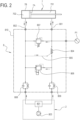
- the baler 1 comprises a hydraulic circuit 8.
- the hydraulic circuit 8 includes a first conduit 801.
- the hydraulic 8 includes a second conduit 802.
- the first conduit 801 is in fluid communication with the closing chamber 701.
- the second conduit 802 is in fluid communication with the opening chamber 702.
- the first conduit 801 and the second conduit 802 are selectively connectable to a pump 803.
- the first conduit 801 and the second conduit 802, in an example, are connectable to the pump through a distributor 811.
- the distributor 811 is movable between three positions. A first position, to connect the pump 803 to the first conduit 801. A second position, to connect the pump 803 to the second conduit 802. A third position, to isolate the pump 803 from the hydraulic circuit 8.
- the pump is connected to an actuating fluid reservoir, not illustrated.
- the actuating fluid reservoir in an example, is provided inside the tractor 2.
- the actuating fluid reservoir in an embodiment, is provided inside the baler 1.
- the pump 803 is provided inside the tractor 2.
- the distributor 811 is provided inside the tractor 2.
- the first conduit 801, in an example, includes a first choker 808.
- the second conduit 802, in an example, includes a second choker 809.
- the first choker 808 and the second choker 809 provide a regulating of the flow of the actuating fluid, respectively in the first conduit 801 and in the second conduit 802.
- the baler 1 includes a binder 12.
- the binder 12, in an embodiment, is provided in the frame 3.
- the binder 12 is configured for binding the bale with a fastening element.
- the baler 1, in an example, includes a pick-up assembly 9.
- the pick-up assembly 9 is configured to collect the crops.
- the pick-up assembly in an example, includes a pick-up shaft having rake teeth.
- the pick-up shaft is configurated to rotate.
- the pick-up assembly 9, in an embodiment, comprises a pair of pick-up wheels 901, movably connected to the ends of the pick-up shaft.
- the baler 1, in an example, includes a pushing rotor.
- the pushing rotor is positioned between the pick-up assembly 9 and the chamber 5, to feed the crops collected by the pick-up assembly 9 to the chamber 5.
- the pick-up assembly itself is configured to feed the collected crops to the chamber 5.
- the baler 1 includes a pressure sensor P1.
- the pressure sensor P1 in an example, is connected to the first conduit 801.
- the pressure sensor P1 is configured for detecting a control signal.
- the control signal is representative of a pressure inside the closing chamber 701.
- the baler 1 includes a control unit.
- the control unit is configured to generate an alert signal as a function of the control signal.
- the hydraulic circuit 8, in an example, includes a hydraulic circuit casing 810.
- the hydraulic circuit casing 810 in an example, is made of aluminum.
- the hydraulic circuit 8, in an example, includes an operating valve 804.
- the operating valve 804, in an example, is inserted in the first conduit 801.
- the operating valve 804, in an example, is inserted in the first conduit 801 between the pump 803 and the closing chamber 701.
- the operating valve 804, in an example, is a non-return valve.
- the operating valve 804, in an example is operable in an open position, for allowing the actuating fluid to flow from the pump 803 to the closing chamber 701, and in a closed position, for retaining the actuating fluid in the closing chamber 701.
- the operating valve 701 allows a flow of the actuating fluid from the pump 803 to the closing chamber 701, but not an opposite flow of the actuating fluid from the closing chamber 701 to the pump 803.
- the pressure sensor P1 is connected to the first conduit 801 downstream of the operating valve 804 (in other words, between the operating valve 804 and the closing chamber 701).
- the driver 805, in an embodiment, is a conduit, which is in fluid communication with the operating valve 804 and with the second conduit 802.
- the driver 805 is connected to the operating valve 804 to force it in the open position, responsive to a pressure in the second conduit 802.
- the driver 805 allows the closing chamber 701 to empty when the opening chamber 702 is filling.
- the hydraulic circuit 8 includes a setting valve 806.
- the setting valve 806 is connected to a conduit that connects the first conduit 801, upstream the operating valve 804, to the second conduit 802.
- the setting valve 806, in an embodiment, is a solenoid valve.
- the setting valve 806 is configured to allow a flow of the actuating fluid from the first conduit 801 to the second conduit 802, when a pressure in the first conduit 801 exceeds a second pressure in the second conduit 802 of a predetermined first threshold value.
- the first threshold value in an example, is 100 bars.
- the hydraulic circuit 8 includes a safety valve 807.
- the safety valve 807 is connected to a conduit that connects the first conduit 801, downstream of the operating valve 804, to the second conduit.
- the safety valve 807 in an example, is a single-effect valve.
- the safety valve 807 is configured to allow a flow of the actuating fluid from the first conduit 801 to the second conduit 802, when a first pressure in the first conduit 801 exceeds a second pressure in the second conduit 802 of a predetermined second threshold value.
- the second threshold value in an example, is 230 bars.
- the present description covers also a method for producing round bales in a baler 1 connected to a tractor 2.
- the method includes a step of moving a tailgate 6 to a closed position.
- the tailgate 6 cooperates with a frame 3 to form a chamber 5 delimited by a plurality of rollers 500.
- the step of moving the tailgate 6 in the closed position includes a connection of a pump 803 to a first conduit 801 and a pressurizing of an actuating fluid in the first conduit 801.
- the first conduit 801 is connected to a closing chamber 701 of a cylinder-piston actuator 7.
- an operating valve 804 positioned in the first conduit between the pump 803 and the closing chamber 701, lets the actuating fluid flowing into the closing chamber 701.
- the actuating fluid by feeding to the closing chamber 701, provides an expansion of the closing chamber 701, resulting in a movement of the piston 7A in a direction that moves the tailgate 6 in the closed position.
- the method in an example, comprises a step of receiving a setting parameter set by the user and representative of a typology of crop to be processed.
- the first threshold value is selected from a plurality of memorized values, in response to the setting parameter.
- the step of moving the tailgate 6 to the closed position last until a setting configuration is reached.
- the setting configuration is detected by a setting valve 806.
- the first threshold value is set (through an electric signal which depends on the setting parameter).
- the setting valve 806 allows a flow of the actuating fluid from the first conduit 801 to the second conduit 802. In that way, the step of moving a tailgate 6 to a closed position ends.
- the method comprises a step of collecting crops.
- the method comprises a step of forming a bale in the chamber 5, by rotating crops received in the chamber 5.
- the crops are collected and received in the chamber 5 through a pick-up assembly 9.
- the method comprises a step of detecting a control signal, representative of a pressure inside the closing chamber 701 of the cylinder-piston actuator 7 (when the tailgate 6 is in the closed position).
- the pressure inside the closing chamber 701 is detected by measuring the pressure of the actuating fluid in the first conduit 801, downstream of the operating valve 804 and the closing chamber 701.
- the method in an example, comprises a step of receiving a user selection representative of a desired density for the formed bale.
- the method in an example, comprises a step of deriving a reference pressure value based on the user selection.
- the bale grows.
- the pressure inside the closing chamber 701 (represented by the control signal) reaches the reference pressure.
- an alert is generated. The alert warns the user to stop an advancing motion of the tractor 2.
- the method provides a step of binding the formed bale with a fastening element.
- the operating valve 804 retains the operating fluid in the closing chamber 701, thus keeping the tailgate 6 closed.
- the method comprises a step of moving the tailgate 6 in an open position, to discharge the formed bale.
- the step of moving the tailgate 6 in the open position includes a connection of the pump 803 to a second conduit 802 and a pressurizing of the actuating fluid in the second conduit 802.
- the second conduit 802 is connected to an opening chamber 702 of a cylinder-piston actuator 7.
- the actuating fluid by feeding to the opening chamber 702, provides an expansion of the opening chamber 702, resulting in a movement of the piston 7A in a direction that moves the tailgate 6 in the open position.
- the operating valve 804 is opened by a driver, to allow the closing chamber 701 to empty.
- the actuating fluid flows from the closing chamber 701 to the distributor 811, through the operating valve 804, which is opened.
- the driver in an example, is a conduit that connects the second conduit 802 to the operating valve 804.
- the pressure of the actuating fluid inside the second conduit 802 wins the elastic force of a spring included in the operating valve 804, resulting in an opening of the operating valve 804.
Landscapes
- Life Sciences & Earth Sciences (AREA)
- Environmental Sciences (AREA)
- Engineering & Computer Science (AREA)
- Mechanical Engineering (AREA)
- Physics & Mathematics (AREA)
- Fluid Mechanics (AREA)
- General Engineering & Computer Science (AREA)
- Fluid-Pressure Circuits (AREA)
- Storage Of Harvested Produce (AREA)
- Agricultural Machines (AREA)
Claims (15)
- Presse à balles (1) pouvant être raccordée à un tracteur (2) pour créer des balles rondes, comprenant :- un cadre (3) supporté sur un essieu de roue (4) ;- une chambre (5) pour recevoir les récoltes et pour loger une balle formée, la chambre ayant une taille fixe prédéterminée ;- un hayon (6) raccordé au cadre et mobile entre une position fermée, pour coopérer avec le cadre (3) afin de délimiter la chambre (5), et une position ouverte, pour décharger la balle formée ;- un ensemble de transport, qui délimite la chambre (5) pour imprimer un mouvement de rotation aux récoltes contenues dans la chambre (5), et a une première portion disposée dans le cadre (3) et une deuxième portion disposée dans le hayon (6) ;- un actionneur cylindre-piston (7), qui inclut une chambre de fermeture (701) et est raccordé au cadre (3) et au hayon (6) pour déplacer le hayon (6) de la position ouverte à la position fermée, lors de la réception d'un fluide d'actionnement dans la chambre de fermeture (701) ;- un dispositif de liage (12), configuré pour lier la balle formée avec un élément de fixation ;- une unité de commande, configurée pour générer un signal d'alerte,- un capteur de pression (P1) pour détecter un signal de commande représentatif d'une pression à l'intérieur de la chambre de fermeture (701) de l'actionneur cylindre-piston (7), dans lequel l'unité de commande est programmée pour générer le signal d'alerte en fonction du signal de commande, dans lequel l'actionneur cylindre-piston (7) est un actionneur à double effet, qui inclut, en plus de la chambre de fermeture (701), une chambre d'ouverture (702), qui peut être alimentée avec le fluide d'actionnement pour commander un mouvement du hayon (6) de la position fermée à la position ouverte, dans lequel l'actionneur cylindre-piston (7) est un actionneur hydraulique et dans lequel la presse à balles (1) comprend un circuit hydraulique (8) incluant :- un premier conduit (801) et un deuxième conduit (802), qui peuvent être raccordés sélectivement à une source de pression et sont en communication fluidique avec la chambre de fermeture (701) et avec la chambre d'ouverture (702) de l'actionneur cylindre-piston (7), respectivement,caractérisé en ce que le circuit hydraulique (8) inclut :- une soupape de réglage (806) qui est raccordé entre le premier conduit (801) et le deuxième conduit (802) et est configurée pour permettre un écoulement du fluide d'actionnement du premier conduit (801) vers le deuxième conduit (802), lorsqu'une première pression dans le premier conduit (801) dépasse une deuxième pression dans le deuxième conduit (802) d'une première valeur de seuil prédéterminée ;- une soupape de sécurité (807) qui est raccordée entre le premier conduit (801) et le deuxième conduit (802) et est configurée pour permettre un écoulement du fluide d'actionnement du premier conduit (801) vers le deuxième conduit (802), lorsque la première pression dans le premier conduit (801) dépasse la deuxième pression dans le deuxième conduit (802) d'une deuxième valeur de seuil prédéterminée, dans lequel la deuxième valeur de seuil est supérieure à la première valeur de seuil.
- Presse à balles (1) selon la revendication 1, dans laquelle le circuit hydraulique (8) inclut :- une soupape de fonctionnement (804), qui est insérée dans le premier conduit (801) et peut fonctionner dans une position ouverte, pour permettre au fluide d'actionnement de s'écouler de la source de pression (803) vers la chambre de fermeture (701), et dans une position fermée, pour retenir le fluide d'actionnement dans la chambre de fermeture (701) ;- un pilote (805), raccordé à la soupape de fonctionnement (804) pour la forcer en position ouverte, sensible à une pression dans le deuxième conduit (802), et dans lequel le capteur de pression (P1) est en communication fluidique avec le premier conduit (801), en aval de la soupape de fonctionnement (804) .
- Presse à balles (1) selon la revendication 2, dans laquelle la soupape de réglage (806) est raccordée en amont de la soupape de fonctionnement (804).
- Presse à balles (1) selon la revendication 3, dans laquelle l'unité de commande est raccordée à la soupape de réglage (806) pour régler la première valeur de seuil dans la soupape de réglage (806) par l'intermédiaire d'un signal électrique, et est configurée pour sélectionner la première valeur de seuil parmi une pluralité de valeurs mémorisées, en fonction d'un paramètre de réglage réglé par l'utilisateur et représentatif d'une typologie de récolte à traiter.
- Presse à balles (1) selon l'une quelconque des revendications 2 à 4, dans laquelle la soupape de sécurité (807) est en aval de la soupape de fonctionnement (804).
- Presse à balles (1) selon l'une quelconque des revendications précédentes, dans laquelle l'unité de commande est programmée pour définir une valeur de pression de référence sur la base d'une sélection de l'utilisateur, et pour comparer le signal de commande à la valeur de pression de référence, pour générer le signal d'alerte en fonction du dépassement de la valeur de pression de référence par le signal de commande.
- Presse à balles (1) selon la revendication 6, comprenant une interface utilisateur, qui peut être positionnée sur le tracteur (2), dans laquelle l'unité de commande est programmée pour afficher, en temps réel au niveau de l'interface utilisateur, des données graphiques représentatives du signal de commande et/ou de la valeur de pression de référence.
- Procédé de production de balles rondes dans une presse à balles (1) raccordée à un tracteur (2), comprenant les étapes suivantes :- déplacer, en alimentant en fluide d'actionnement une chambre de fermeture (701) d'un actionneur cylindre-piston (7), un hayon (6) vers une position fermée, où le hayon coopère avec un cadre (3) pour former une chambre (5) ;- former une balle dans la chambre (5), en faisant tourner les récoltes reçues dans la chambre (5), dans laquelle la taille de la chambre (5) reste fixe pendant la formation de la balle ;- générer un signal d'alerte, pour fournir à l'utilisateur des informations sur un fonctionnement ou un état de la presse à balles (1) ;- lier la balle formée avec un élément de fixation ;- déplacer le hayon (6) vers une position ouverte, pour décharger la balle liée,- détecter un signal de commande, représentatif d'une pression à l'intérieur de la chambre de fermeture (701) de l'actionneur cylindre-piston (7), lorsque le hayon (6) est en position fermée, dans lequel le signal d'alerte est généré en fonction du signal de commande dans lequel l'étape de déplacement du hayon vers la position ouverte estaccomplie en alimentant en fluide d'actionnement une chambre d'ouverture (702) de l'actionneur cylindre-piston (7), qui est un actionneur à double effet, dans lequel l'actionneur cylindre-piston (7) est un actionneur hydraulique et dans lequel la presse à balles (1) comprend un circuit hydraulique (8) incluant :- un premier conduit (801) et un deuxième conduit (802), qui peuvent être raccordés sélectivement à une source de pression et sont en communication fluidique avec la chambre de fermeture (701) et avec la chambre d'ouverture (702) de l'actionneur cylindre-piston (7), respectivement, caractérisés en ce que le circuit hydraulique (8) inclut :- une soupape de réglage (806) qui est raccordée entre le premier conduit (801) et le deuxième conduit (802) pour permettre un écoulement du fluide d'actionnement du premier conduit (801) vers le deuxième conduit (802), lorsqu'une première pression dans le premier conduit (801) dépasse une deuxième pression dans le deuxième conduit (802) d'une première valeur de seuil prédéterminée ;- une soupape de sécurité (807), qui est raccordée entre le premier conduit (801) 15 et le deuxième conduit (802) pour permettre un écoulement du fluide d'actionnement du premier conduit (801) vers le deuxième conduit (802), lorsque la première pression dans le premier conduit (801) dépasse la deuxième pression dans le deuxième conduit (802) d'une deuxième valeur de seuil prédéterminée, dans lequel la deuxième valeur de seuil est supérieure à la première valeur de seuil.
- Procédé selon la revendication 8, comprenant les étapes suivantes :- recevoir une sélection d'utilisateur représentative d'une densité souhaitée pour la balle formée ;- dériver une valeur de pression de référence basée sur la sélection de l'utilisateur, dans laquelle le signal d'alerte est généré lorsque le signal de commande dépasse la valeur de pression de référence.
- Procédé selon la revendication 9, comprenant une étape d'affichage, en temps réel au niveau d'une interface utilisateur, de données graphiques représentatives du signal de commande et/ou de la valeur de pression de référence.
- Procédé selon l'une quelconque des revendications 8 à 10, dans lequel, dans l'étape de déplacer le hayon (6) vers la position fermée, le fluide d'actionnement est fourni à la chambre de fermeture (701) par l'intermédiaire d'une soupape de fonctionnement (804), qui est configurée pour retenir le fluide d'actionnement dans la chambre de fermeture (701), et dans lequel la pression à l'intérieur de la chambre de fermeture (701) est détectée en mesurant une pression d'un premier conduit (801) qui met en communication fluidique la soupape de fonctionnement (804) et la chambre de fermeture (701).
- Procédé selon la revendication 11, dans lequel la soupape de fonctionnement (804) est forcée dans une position ouverte, pour libérer le fluide d'actionnement de la chambre de fermeture (701), en réponse à une pression du fluide d'actionnement dans la chambre d'ouverture (702).
- Procédé selon l'une quelconque des revendications 8 à 12, dans lequel, dans l'étape de déplacer le hayon (6) vers la position fermée, le fluide d'actionnement est fourni à la chambre de fermeture (701) jusqu'à ce qu'une configuration de réglage soit atteinte, en fonction d'une première valeur de seuil.
- Procédé selon la revendication 13, comprenant une étape de recevoir un paramètre de réglage réglé par l'utilisateur et représentatif d'une typologie de récolte à traiter, dans lequel la première valeur de seuil est sélectionnée parmi une pluralité de valeurs mémorisées, en réponse au paramètre de réglage.
- Procédé selon l'une quelconque des revendications 8 à 14, dans lequel l'instant où la balle est complètement formée est déterminé par le signal de commande, représentatif d'une pression à l'intérieur de la chambre de fermeture.
Priority Applications (1)
| Application Number | Priority Date | Filing Date | Title |
|---|---|---|---|
| EP23157107.6A EP4201195B1 (fr) | 2017-08-11 | 2018-08-09 | Presse à balles pouvant être reliée à un tracteur pour fournir des balles rondes et procédé de production de balles rondes |
Applications Claiming Priority (2)
| Application Number | Priority Date | Filing Date | Title |
|---|---|---|---|
| IT102017000093544A IT201700093544A1 (it) | 2017-08-11 | 2017-08-11 | Imballatore connettibile ad un trattore per realizzare balle rotonde e metodo per realizzare balle rotonde |
| PCT/IB2018/056006 WO2019030704A1 (fr) | 2017-08-11 | 2018-08-09 | Presse à balles pouvant être reliée à un tracteur pour créer des balles rondes et procédé de production de balles rondes |
Related Child Applications (2)
| Application Number | Title | Priority Date | Filing Date |
|---|---|---|---|
| EP23157107.6A Division EP4201195B1 (fr) | 2017-08-11 | 2018-08-09 | Presse à balles pouvant être reliée à un tracteur pour fournir des balles rondes et procédé de production de balles rondes |
| EP23157107.6A Division-Into EP4201195B1 (fr) | 2017-08-11 | 2018-08-09 | Presse à balles pouvant être reliée à un tracteur pour fournir des balles rondes et procédé de production de balles rondes |
Publications (2)
| Publication Number | Publication Date |
|---|---|
| EP3664596A1 EP3664596A1 (fr) | 2020-06-17 |
| EP3664596B1 true EP3664596B1 (fr) | 2023-11-08 |
Family
ID=60628097
Family Applications (2)
| Application Number | Title | Priority Date | Filing Date |
|---|---|---|---|
| EP18762154.5A Active EP3664596B1 (fr) | 2017-08-11 | 2018-08-09 | Presse à balles pouvant être reliée à un tracteur pour créer des balles rondes et procédé de production de balles rondes |
| EP23157107.6A Active EP4201195B1 (fr) | 2017-08-11 | 2018-08-09 | Presse à balles pouvant être reliée à un tracteur pour fournir des balles rondes et procédé de production de balles rondes |
Family Applications After (1)
| Application Number | Title | Priority Date | Filing Date |
|---|---|---|---|
| EP23157107.6A Active EP4201195B1 (fr) | 2017-08-11 | 2018-08-09 | Presse à balles pouvant être reliée à un tracteur pour fournir des balles rondes et procédé de production de balles rondes |
Country Status (9)
| Country | Link |
|---|---|
| US (2) | US11696532B2 (fr) |
| EP (2) | EP3664596B1 (fr) |
| AU (1) | AU2018315740B2 (fr) |
| CA (1) | CA3071514A1 (fr) |
| ES (2) | ES3030321T3 (fr) |
| IT (1) | IT201700093544A1 (fr) |
| LT (2) | LT3664596T (fr) |
| PL (2) | PL4201195T3 (fr) |
| WO (1) | WO2019030704A1 (fr) |
Cited By (1)
| Publication number | Priority date | Publication date | Assignee | Title |
|---|---|---|---|---|
| EP4635290A1 (fr) | 2024-04-16 | 2025-10-22 | Kverneland Group Ravenna S.r.l. | Procédé de formation d'une balle par une presse à balles, système agricole et presse à balles |
Families Citing this family (9)
| Publication number | Priority date | Publication date | Assignee | Title |
|---|---|---|---|---|
| CN111742721B (zh) * | 2019-03-28 | 2021-12-14 | 绛县星源科技有限公司 | 一种车载不停车双圆捆打捆机作业控制方法及系统 |
| IT202000000928A1 (it) | 2020-01-20 | 2021-07-20 | Kverneland Group Ravenna Srl | Rotopressa |
| US11519429B2 (en) * | 2020-04-22 | 2022-12-06 | Deere & Company | Hydraulic system for baler implement gate |
| US11547057B2 (en) | 2020-04-22 | 2023-01-10 | Deere & Company | Hydraulic dampening system for a rear gate of a round baler |
| US20230232748A1 (en) * | 2020-07-30 | 2023-07-27 | Mchale Engineering | A baler and method and apparatus for determining uniformity of the density of a round bale |
| CN114115209B (zh) * | 2020-08-11 | 2023-08-18 | 宇通客车股份有限公司 | 一种车辆、车辆避障方法及装置 |
| DE102022134299A1 (de) | 2022-12-21 | 2024-06-27 | Pöttinger Landtechnik Gmbh | Landwirtschaftliche Ballenpresse |
| US20250057085A1 (en) * | 2023-08-15 | 2025-02-20 | Cnh Industrial America Llc | Regenerative tailgate circuit |
| EP4552477A1 (fr) | 2023-11-10 | 2025-05-14 | Kverneland Group Ravenna S.r.l. | Presse à balles et procédé de formation de balles |
Family Cites Families (32)
| Publication number | Priority date | Publication date | Assignee | Title |
|---|---|---|---|---|
| FR2604855B1 (fr) * | 1986-10-09 | 1990-11-02 | Hesston Sa | Dispositif d'ejection d'une balle formee dans une presse a balles cylindriques |
| US5165332A (en) * | 1990-01-11 | 1992-11-24 | Gehl Company | Bale density monitoring apparatus and method |
| IT1277868B1 (it) * | 1995-07-24 | 1997-11-12 | Antonio Feraboli | Rotopressa per la raccolta e la formazione di balle cilindriche di foraggio o paglia, del tipo a camera variabile, con camera di |
| DE19910555A1 (de) * | 1999-03-10 | 2000-09-14 | Lely Welger Maschinenfabrik Gm | Landwirtschaftliche Rundballenpresse mit einer Wägeeinrichtung |
| DE10303201C5 (de) * | 2003-01-28 | 2015-03-12 | Lely Vermeer Maschinenfabrik GmbH | Rundballenpresse für landwirtschaftliche Halmgüter |
| DE102004022801A1 (de) * | 2004-05-08 | 2005-12-15 | Deere & Company, Moline | Rundballenpresse |
| US7472649B1 (en) * | 2007-09-28 | 2009-01-06 | Deere & Company | Sequence and timing control for large round baler ejection device |
| US7805914B2 (en) * | 2008-03-10 | 2010-10-05 | Cnh America Llc | Hydraulic bale kicker with optional weighing device |
| US7849791B2 (en) * | 2008-11-10 | 2010-12-14 | Cnh America Llc | Optimized baler tailgate cycle |
| KR101359935B1 (ko) * | 2012-02-09 | 2014-02-12 | 허우영 | 첨가제 정량 투입 장치가 구비된 원형 곤포 결속기 |
| US9295198B2 (en) * | 2012-05-09 | 2016-03-29 | Cnh Industrial America Llc | Density system bypass for a round baler |
| JP5701248B2 (ja) * | 2012-05-24 | 2015-04-15 | 日立建機株式会社 | 油圧閉回路システム |
| CN103141229A (zh) | 2013-02-01 | 2013-06-12 | 中机美诺科技股份有限公司 | 一种适用于捡拾圆捆机的可调节草捆密度的液压控制装置 |
| KR101425869B1 (ko) * | 2013-04-30 | 2014-08-01 | 주식회사 동조 | 베일러 뒷문 자동 개폐 장치, 이를 이용한 자동 개폐 방법 및 자동 개폐 시스템 |
| US9107348B2 (en) * | 2013-11-25 | 2015-08-18 | Cnh Industrial America Llc | Fluid circuit for bale ejection |
| US9113599B2 (en) * | 2013-11-25 | 2015-08-25 | Cnh Industrial America Llc | Fluid circuit for bale ejection with restricted flow |
| US9980437B2 (en) * | 2014-03-25 | 2018-05-29 | CNH Industrial American LLC | Baling system having a bale position sensor |
| US9713306B2 (en) * | 2015-06-09 | 2017-07-25 | Cnh Industrial America Llc | Electrohydraulic circuit for a drop floor assembly |
| DE102015211035A1 (de) | 2015-06-16 | 2016-12-22 | Deere & Company | Rundballenpresse mit einem Sensor zur Erfassung der Ballengröße |
| US10595465B2 (en) * | 2016-04-08 | 2020-03-24 | Deere & Company | Agricultural baler including baler gate control system |
| WO2018056805A1 (fr) * | 2016-09-23 | 2018-03-29 | Lely Patent N.V. | Appareil et procédé de formation et éjection d'une balle en fonction d'un capteur de rampe |
| PL3351086T3 (pl) * | 2017-01-20 | 2020-11-02 | Deere & Company | Układ do belowania |
| DE102017213436A1 (de) * | 2017-08-02 | 2019-02-07 | Deere & Company | Einrichtung zur Steuerung der Auslassklappe einer Ballenpresse, Ballenpresse und Verfahren |
| EP3569055B1 (fr) * | 2018-05-18 | 2021-04-07 | Deere & Company | Presse à balles rondes |
| CN109156178B (zh) * | 2018-08-14 | 2021-09-24 | 内蒙古农业大学 | 一种圆捆机监控系统及方法 |
| US10537066B1 (en) * | 2018-09-25 | 2020-01-21 | Redlands Ashlyn Motors, PLC | Continuous baler |
| US11051456B2 (en) * | 2019-01-02 | 2021-07-06 | Deere & Company | Bale weight measurement and control system using liftgate |
| US10653067B1 (en) * | 2019-05-21 | 2020-05-19 | Deere & Company | Crop package accumulator |
| US11105351B2 (en) * | 2019-09-20 | 2021-08-31 | Cnh Industrial America Llc | Agricultural baler with hydraulic flow controller |
| CN114945270B (zh) * | 2020-01-20 | 2024-04-02 | 阿瑟琳红土地汽车制造私人有限公司 | 连续打捆机 |
| US11519429B2 (en) * | 2020-04-22 | 2022-12-06 | Deere & Company | Hydraulic system for baler implement gate |
| US11547057B2 (en) * | 2020-04-22 | 2023-01-10 | Deere & Company | Hydraulic dampening system for a rear gate of a round baler |
-
2017
- 2017-08-11 IT IT102017000093544A patent/IT201700093544A1/it unknown
-
2018
- 2018-08-09 LT LTEPPCT/IB2018/056006T patent/LT3664596T/lt unknown
- 2018-08-09 EP EP18762154.5A patent/EP3664596B1/fr active Active
- 2018-08-09 ES ES23157107T patent/ES3030321T3/es active Active
- 2018-08-09 AU AU2018315740A patent/AU2018315740B2/en active Active
- 2018-08-09 LT LTEP23157107.6T patent/LT4201195T/lt unknown
- 2018-08-09 ES ES18762154T patent/ES2969216T3/es active Active
- 2018-08-09 US US16/630,961 patent/US11696532B2/en active Active
- 2018-08-09 PL PL23157107.6T patent/PL4201195T3/pl unknown
- 2018-08-09 PL PL18762154.5T patent/PL3664596T3/pl unknown
- 2018-08-09 EP EP23157107.6A patent/EP4201195B1/fr active Active
- 2018-08-09 WO PCT/IB2018/056006 patent/WO2019030704A1/fr not_active Ceased
- 2018-08-09 CA CA3071514A patent/CA3071514A1/fr active Pending
-
2023
- 2023-05-22 US US18/200,498 patent/US12066038B2/en active Active
Cited By (2)
| Publication number | Priority date | Publication date | Assignee | Title |
|---|---|---|---|---|
| EP4635290A1 (fr) | 2024-04-16 | 2025-10-22 | Kverneland Group Ravenna S.r.l. | Procédé de formation d'une balle par une presse à balles, système agricole et presse à balles |
| WO2025219872A1 (fr) | 2024-04-16 | 2025-10-23 | Kverneland Group Ravenna S.R.L. | Procédé de formation d'une balle par une presse à balles, système agricole et presse à balles |
Also Published As
| Publication number | Publication date |
|---|---|
| LT4201195T (lt) | 2025-05-12 |
| NZ760593A (en) | 2025-03-28 |
| PL4201195T3 (pl) | 2025-06-16 |
| ES2969216T3 (es) | 2024-05-17 |
| EP4201195B1 (fr) | 2025-02-26 |
| AU2018315740A1 (en) | 2020-01-30 |
| EP3664596A1 (fr) | 2020-06-17 |
| CA3071514A1 (fr) | 2019-02-14 |
| US12066038B2 (en) | 2024-08-20 |
| LT3664596T (lt) | 2024-02-12 |
| PL3664596T3 (pl) | 2024-05-06 |
| AU2018315740B2 (en) | 2024-01-18 |
| WO2019030704A1 (fr) | 2019-02-14 |
| US11696532B2 (en) | 2023-07-11 |
| ES3030321T3 (en) | 2025-06-27 |
| EP4201195A1 (fr) | 2023-06-28 |
| US20200221643A1 (en) | 2020-07-16 |
| IT201700093544A1 (it) | 2019-02-11 |
| US20230292670A1 (en) | 2023-09-21 |
Similar Documents
| Publication | Publication Date | Title |
|---|---|---|
| US12066038B2 (en) | Baler connectable to a tractor for providing round bales and method for producing round bales | |
| US7331279B2 (en) | Round baling press | |
| EP2458965B1 (fr) | Presse enrouleuse continue avec pickup | |
| EP3062600B1 (fr) | Appareil et procédé de formation de balle avec une protection contre la surcharge | |
| EP3308631B1 (fr) | Machine de récolte agricole | |
| AU2019370936B2 (en) | A baling machine including a drive-transferring driveline | |
| EP3695705B1 (fr) | Machine de récolte avec système de détection de débit de récolte | |
| AU2019373378B2 (en) | Improvements in or relating to agricultural baling machines | |
| EP4165962B1 (fr) | Appareil de mise en balles | |
| EP3782456B1 (fr) | Ramasseuse-presse agricole dotée d'une commande de verrouillage de hayon | |
| EP4552477A1 (fr) | Presse à balles et procédé de formation de balles | |
| NZ760593B2 (en) | Baler connectable to a tractor for providing round bales and method for producing round bales |
Legal Events
| Date | Code | Title | Description |
|---|---|---|---|
| STAA | Information on the status of an ep patent application or granted ep patent |
Free format text: STATUS: UNKNOWN |
|
| STAA | Information on the status of an ep patent application or granted ep patent |
Free format text: STATUS: THE INTERNATIONAL PUBLICATION HAS BEEN MADE |
|
| PUAI | Public reference made under article 153(3) epc to a published international application that has entered the european phase |
Free format text: ORIGINAL CODE: 0009012 |
|
| STAA | Information on the status of an ep patent application or granted ep patent |
Free format text: STATUS: REQUEST FOR EXAMINATION WAS MADE |
|
| 17P | Request for examination filed |
Effective date: 20200110 |
|
| AK | Designated contracting states |
Kind code of ref document: A1 Designated state(s): AL AT BE BG CH CY CZ DE DK EE ES FI FR GB GR HR HU IE IS IT LI LT LU LV MC MK MT NL NO PL PT RO RS SE SI SK SM TR |
|
| AX | Request for extension of the european patent |
Extension state: BA ME |
|
| DAV | Request for validation of the european patent (deleted) | ||
| DAX | Request for extension of the european patent (deleted) | ||
| STAA | Information on the status of an ep patent application or granted ep patent |
Free format text: STATUS: EXAMINATION IS IN PROGRESS |
|
| 17Q | First examination report despatched |
Effective date: 20220303 |
|
| GRAP | Despatch of communication of intention to grant a patent |
Free format text: ORIGINAL CODE: EPIDOSNIGR1 |
|
| STAA | Information on the status of an ep patent application or granted ep patent |
Free format text: STATUS: GRANT OF PATENT IS INTENDED |
|
| P01 | Opt-out of the competence of the unified patent court (upc) registered |
Effective date: 20230525 |
|
| INTG | Intention to grant announced |
Effective date: 20230705 |
|
| GRAS | Grant fee paid |
Free format text: ORIGINAL CODE: EPIDOSNIGR3 |
|
| GRAA | (expected) grant |
Free format text: ORIGINAL CODE: 0009210 |
|
| STAA | Information on the status of an ep patent application or granted ep patent |
Free format text: STATUS: THE PATENT HAS BEEN GRANTED |
|
| AK | Designated contracting states |
Kind code of ref document: B1 Designated state(s): AL AT BE BG CH CY CZ DE DK EE ES FI FR GB GR HR HU IE IS IT LI LT LU LV MC MK MT NL NO PL PT RO RS SE SI SK SM TR |
|
| REG | Reference to a national code |
Ref country code: GB Ref legal event code: FG4D |
|
| REG | Reference to a national code |
Ref country code: CH Ref legal event code: EP |
|
| REG | Reference to a national code |
Ref country code: DE Ref legal event code: R096 Ref document number: 602018060822 Country of ref document: DE |
|
| REG | Reference to a national code |
Ref country code: IE Ref legal event code: FG4D |
|
| REG | Reference to a national code |
Ref country code: NL Ref legal event code: FP |
|
| REG | Reference to a national code |
Ref country code: SE Ref legal event code: TRGR |
|
| PG25 | Lapsed in a contracting state [announced via postgrant information from national office to epo] |
Ref country code: GR Free format text: LAPSE BECAUSE OF FAILURE TO SUBMIT A TRANSLATION OF THE DESCRIPTION OR TO PAY THE FEE WITHIN THE PRESCRIBED TIME-LIMIT Effective date: 20240209 |
|
| PG25 | Lapsed in a contracting state [announced via postgrant information from national office to epo] |
Ref country code: IS Free format text: LAPSE BECAUSE OF FAILURE TO SUBMIT A TRANSLATION OF THE DESCRIPTION OR TO PAY THE FEE WITHIN THE PRESCRIBED TIME-LIMIT Effective date: 20240308 |
|
| PG25 | Lapsed in a contracting state [announced via postgrant information from national office to epo] |
Ref country code: IS Free format text: LAPSE BECAUSE OF FAILURE TO SUBMIT A TRANSLATION OF THE DESCRIPTION OR TO PAY THE FEE WITHIN THE PRESCRIBED TIME-LIMIT Effective date: 20240308 Ref country code: GR Free format text: LAPSE BECAUSE OF FAILURE TO SUBMIT A TRANSLATION OF THE DESCRIPTION OR TO PAY THE FEE WITHIN THE PRESCRIBED TIME-LIMIT Effective date: 20240209 Ref country code: BG Free format text: LAPSE BECAUSE OF FAILURE TO SUBMIT A TRANSLATION OF THE DESCRIPTION OR TO PAY THE FEE WITHIN THE PRESCRIBED TIME-LIMIT Effective date: 20240208 Ref country code: PT Free format text: LAPSE BECAUSE OF FAILURE TO SUBMIT A TRANSLATION OF THE DESCRIPTION OR TO PAY THE FEE WITHIN THE PRESCRIBED TIME-LIMIT Effective date: 20240308 |
|
| REG | Reference to a national code |
Ref country code: ES Ref legal event code: FG2A Ref document number: 2969216 Country of ref document: ES Kind code of ref document: T3 Effective date: 20240517 |
|
| PG25 | Lapsed in a contracting state [announced via postgrant information from national office to epo] |
Ref country code: RS Free format text: LAPSE BECAUSE OF FAILURE TO SUBMIT A TRANSLATION OF THE DESCRIPTION OR TO PAY THE FEE WITHIN THE PRESCRIBED TIME-LIMIT Effective date: 20231108 Ref country code: NO Free format text: LAPSE BECAUSE OF FAILURE TO SUBMIT A TRANSLATION OF THE DESCRIPTION OR TO PAY THE FEE WITHIN THE PRESCRIBED TIME-LIMIT Effective date: 20240208 Ref country code: HR Free format text: LAPSE BECAUSE OF FAILURE TO SUBMIT A TRANSLATION OF THE DESCRIPTION OR TO PAY THE FEE WITHIN THE PRESCRIBED TIME-LIMIT Effective date: 20231108 |
|
| PG25 | Lapsed in a contracting state [announced via postgrant information from national office to epo] |
Ref country code: DK Free format text: LAPSE BECAUSE OF FAILURE TO SUBMIT A TRANSLATION OF THE DESCRIPTION OR TO PAY THE FEE WITHIN THE PRESCRIBED TIME-LIMIT Effective date: 20231108 |
|
| REG | Reference to a national code |
Ref country code: AT Ref legal event code: UEP Ref document number: 1628764 Country of ref document: AT Kind code of ref document: T Effective date: 20231108 |
|
| PG25 | Lapsed in a contracting state [announced via postgrant information from national office to epo] |
Ref country code: SK Free format text: LAPSE BECAUSE OF FAILURE TO SUBMIT A TRANSLATION OF THE DESCRIPTION OR TO PAY THE FEE WITHIN THE PRESCRIBED TIME-LIMIT Effective date: 20231108 |
|
| PG25 | Lapsed in a contracting state [announced via postgrant information from national office to epo] |
Ref country code: SM Free format text: LAPSE BECAUSE OF FAILURE TO SUBMIT A TRANSLATION OF THE DESCRIPTION OR TO PAY THE FEE WITHIN THE PRESCRIBED TIME-LIMIT Effective date: 20231108 Ref country code: SK Free format text: LAPSE BECAUSE OF FAILURE TO SUBMIT A TRANSLATION OF THE DESCRIPTION OR TO PAY THE FEE WITHIN THE PRESCRIBED TIME-LIMIT Effective date: 20231108 Ref country code: RO Free format text: LAPSE BECAUSE OF FAILURE TO SUBMIT A TRANSLATION OF THE DESCRIPTION OR TO PAY THE FEE WITHIN THE PRESCRIBED TIME-LIMIT Effective date: 20231108 Ref country code: EE Free format text: LAPSE BECAUSE OF FAILURE TO SUBMIT A TRANSLATION OF THE DESCRIPTION OR TO PAY THE FEE WITHIN THE PRESCRIBED TIME-LIMIT Effective date: 20231108 Ref country code: DK Free format text: LAPSE BECAUSE OF FAILURE TO SUBMIT A TRANSLATION OF THE DESCRIPTION OR TO PAY THE FEE WITHIN THE PRESCRIBED TIME-LIMIT Effective date: 20231108 |
|
| REG | Reference to a national code |
Ref country code: DE Ref legal event code: R097 Ref document number: 602018060822 Country of ref document: DE |
|
| PLBE | No opposition filed within time limit |
Free format text: ORIGINAL CODE: 0009261 |
|
| STAA | Information on the status of an ep patent application or granted ep patent |
Free format text: STATUS: NO OPPOSITION FILED WITHIN TIME LIMIT |
|
| 26N | No opposition filed |
Effective date: 20240809 |
|
| PG25 | Lapsed in a contracting state [announced via postgrant information from national office to epo] |
Ref country code: SI Free format text: LAPSE BECAUSE OF FAILURE TO SUBMIT A TRANSLATION OF THE DESCRIPTION OR TO PAY THE FEE WITHIN THE PRESCRIBED TIME-LIMIT Effective date: 20231108 |
|
| PG25 | Lapsed in a contracting state [announced via postgrant information from national office to epo] |
Ref country code: SI Free format text: LAPSE BECAUSE OF FAILURE TO SUBMIT A TRANSLATION OF THE DESCRIPTION OR TO PAY THE FEE WITHIN THE PRESCRIBED TIME-LIMIT Effective date: 20231108 |
|
| REG | Reference to a national code |
Ref country code: CH Ref legal event code: PL |
|
| PG25 | Lapsed in a contracting state [announced via postgrant information from national office to epo] |
Ref country code: LU Free format text: LAPSE BECAUSE OF NON-PAYMENT OF DUE FEES Effective date: 20240809 |
|
| PG25 | Lapsed in a contracting state [announced via postgrant information from national office to epo] |
Ref country code: CH Free format text: LAPSE BECAUSE OF NON-PAYMENT OF DUE FEES Effective date: 20240831 Ref country code: MC Free format text: LAPSE BECAUSE OF FAILURE TO SUBMIT A TRANSLATION OF THE DESCRIPTION OR TO PAY THE FEE WITHIN THE PRESCRIBED TIME-LIMIT Effective date: 20231108 |
|
| PGFP | Annual fee paid to national office [announced via postgrant information from national office to epo] |
Ref country code: NL Payment date: 20250821 Year of fee payment: 8 |
|
| PG25 | Lapsed in a contracting state [announced via postgrant information from national office to epo] |
Ref country code: FI Free format text: LAPSE BECAUSE OF FAILURE TO SUBMIT A TRANSLATION OF THE DESCRIPTION OR TO PAY THE FEE WITHIN THE PRESCRIBED TIME-LIMIT Effective date: 20231108 |
|
| PGFP | Annual fee paid to national office [announced via postgrant information from national office to epo] |
Ref country code: ES Payment date: 20250926 Year of fee payment: 8 |
|
| PGFP | Annual fee paid to national office [announced via postgrant information from national office to epo] |
Ref country code: LT Payment date: 20250723 Year of fee payment: 8 Ref country code: DE Payment date: 20250820 Year of fee payment: 8 |
|
| PGFP | Annual fee paid to national office [announced via postgrant information from national office to epo] |
Ref country code: PL Payment date: 20250731 Year of fee payment: 8 Ref country code: IT Payment date: 20250825 Year of fee payment: 8 |
|
| PGFP | Annual fee paid to national office [announced via postgrant information from national office to epo] |
Ref country code: BE Payment date: 20250820 Year of fee payment: 8 Ref country code: GB Payment date: 20250820 Year of fee payment: 8 |
|
| PGFP | Annual fee paid to national office [announced via postgrant information from national office to epo] |
Ref country code: FR Payment date: 20250828 Year of fee payment: 8 Ref country code: AT Payment date: 20250821 Year of fee payment: 8 |
|
| PGFP | Annual fee paid to national office [announced via postgrant information from national office to epo] |
Ref country code: SE Payment date: 20250820 Year of fee payment: 8 |
|
| PGFP | Annual fee paid to national office [announced via postgrant information from national office to epo] |
Ref country code: IE Payment date: 20250820 Year of fee payment: 8 Ref country code: CZ Payment date: 20250804 Year of fee payment: 8 |
|
| PGFP | Annual fee paid to national office [announced via postgrant information from national office to epo] |
Ref country code: LV Payment date: 20250818 Year of fee payment: 8 |