EP3664588B1 - System for managing the temperature in an electric envelope - Google Patents
System for managing the temperature in an electric envelope Download PDFInfo
- Publication number
- EP3664588B1 EP3664588B1 EP19207752.7A EP19207752A EP3664588B1 EP 3664588 B1 EP3664588 B1 EP 3664588B1 EP 19207752 A EP19207752 A EP 19207752A EP 3664588 B1 EP3664588 B1 EP 3664588B1
- Authority
- EP
- European Patent Office
- Prior art keywords
- volume
- air
- outlet
- temperature
- air inlet
- Prior art date
- Legal status (The legal status is an assumption and is not a legal conclusion. Google has not performed a legal analysis and makes no representation as to the accuracy of the status listed.)
- Active
Links
- 239000000463 material Substances 0.000 claims description 10
- 230000004913 activation Effects 0.000 claims description 8
- 238000010616 electrical installation Methods 0.000 claims description 4
- 238000000034 method Methods 0.000 claims description 4
- 238000009529 body temperature measurement Methods 0.000 claims description 3
- 101150015071 vent1 gene Proteins 0.000 claims description 3
- 238000009434 installation Methods 0.000 claims description 2
- 230000000903 blocking effect Effects 0.000 claims 2
- 230000002459 sustained effect Effects 0.000 claims 2
- 102100032919 Chromobox protein homolog 1 Human genes 0.000 description 7
- 101000797584 Homo sapiens Chromobox protein homolog 1 Proteins 0.000 description 7
- 238000009423 ventilation Methods 0.000 description 3
- 230000033228 biological regulation Effects 0.000 description 2
- 230000015572 biosynthetic process Effects 0.000 description 2
- 238000005259 measurement Methods 0.000 description 2
- 101100446506 Mus musculus Fgf3 gene Proteins 0.000 description 1
- 238000004378 air conditioning Methods 0.000 description 1
- 230000000295 complement effect Effects 0.000 description 1
- 230000005494 condensation Effects 0.000 description 1
- 238000009833 condensation Methods 0.000 description 1
- 230000007423 decrease Effects 0.000 description 1
- 230000000593 degrading effect Effects 0.000 description 1
- 238000010438 heat treatment Methods 0.000 description 1
- 239000007769 metal material Substances 0.000 description 1
- 238000000926 separation method Methods 0.000 description 1
Images


Classifications
-
- H—ELECTRICITY
- H05—ELECTRIC TECHNIQUES NOT OTHERWISE PROVIDED FOR
- H05K—PRINTED CIRCUITS; CASINGS OR CONSTRUCTIONAL DETAILS OF ELECTRIC APPARATUS; MANUFACTURE OF ASSEMBLAGES OF ELECTRICAL COMPONENTS
- H05K7/00—Constructional details common to different types of electric apparatus
- H05K7/20—Modifications to facilitate cooling, ventilating, or heating
- H05K7/20536—Modifications to facilitate cooling, ventilating, or heating for racks or cabinets of standardised dimensions, e.g. electronic racks for aircraft or telecommunication equipment
- H05K7/20618—Air circulating in different modes under control of air guidance flaps
-
- H—ELECTRICITY
- H05—ELECTRIC TECHNIQUES NOT OTHERWISE PROVIDED FOR
- H05K—PRINTED CIRCUITS; CASINGS OR CONSTRUCTIONAL DETAILS OF ELECTRIC APPARATUS; MANUFACTURE OF ASSEMBLAGES OF ELECTRICAL COMPONENTS
- H05K7/00—Constructional details common to different types of electric apparatus
- H05K7/20—Modifications to facilitate cooling, ventilating, or heating
- H05K7/20536—Modifications to facilitate cooling, ventilating, or heating for racks or cabinets of standardised dimensions, e.g. electronic racks for aircraft or telecommunication equipment
- H05K7/20554—Forced ventilation of a gaseous coolant
- H05K7/20572—Forced ventilation of a gaseous coolant within cabinets for removing heat from sub-racks, e.g. plenum
-
- H—ELECTRICITY
- H05—ELECTRIC TECHNIQUES NOT OTHERWISE PROVIDED FOR
- H05K—PRINTED CIRCUITS; CASINGS OR CONSTRUCTIONAL DETAILS OF ELECTRIC APPARATUS; MANUFACTURE OF ASSEMBLAGES OF ELECTRICAL COMPONENTS
- H05K7/00—Constructional details common to different types of electric apparatus
- H05K7/20—Modifications to facilitate cooling, ventilating, or heating
- H05K7/20536—Modifications to facilitate cooling, ventilating, or heating for racks or cabinets of standardised dimensions, e.g. electronic racks for aircraft or telecommunication equipment
- H05K7/206—Air circulating in closed loop within cabinets wherein heat is removed through air-to-air heat-exchanger
-
- H—ELECTRICITY
- H05—ELECTRIC TECHNIQUES NOT OTHERWISE PROVIDED FOR
- H05K—PRINTED CIRCUITS; CASINGS OR CONSTRUCTIONAL DETAILS OF ELECTRIC APPARATUS; MANUFACTURE OF ASSEMBLAGES OF ELECTRICAL COMPONENTS
- H05K7/00—Constructional details common to different types of electric apparatus
- H05K7/20—Modifications to facilitate cooling, ventilating, or heating
- H05K7/20536—Modifications to facilitate cooling, ventilating, or heating for racks or cabinets of standardised dimensions, e.g. electronic racks for aircraft or telecommunication equipment
- H05K7/207—Thermal management, e.g. cabinet temperature control
-
- H—ELECTRICITY
- H02—GENERATION; CONVERSION OR DISTRIBUTION OF ELECTRIC POWER
- H02B—BOARDS, SUBSTATIONS OR SWITCHING ARRANGEMENTS FOR THE SUPPLY OR DISTRIBUTION OF ELECTRIC POWER
- H02B1/00—Frameworks, boards, panels, desks, casings; Details of substations or switching arrangements
- H02B1/56—Cooling; Ventilation
- H02B1/565—Cooling; Ventilation for cabinets
Definitions
- the present invention relates to a temperature management system in an electrical enclosure.
- the invention also relates to a method for managing the temperature implemented using said system.
- the management of the temperature in the enclosure of an electrical enclosure is a question dealt with on a recurring basis.
- the devices present in the enclosure tend to heat up and it is therefore necessary to maintain the temperature inside the enclosure below a certain threshold, otherwise there is a risk of degrading the devices.
- An air conditioning and/or heating solution can be used respectively as a replacement or as a complement in order to regulate the temperature inside the envelope.
- the system includes a third mode of operation in which the control and processing unit controls the first air transfer means and the second air transfer means to block any flow of air respectively between the first volume and the second volume and between the first volume and the third volume.
- the system comprises means for determining a first period of activation of the first air transfer means and second air transfer means and a second period of activation of the first means of air transfer and second air transfer means.
- the system includes a temperature sensor configured to supply the minimum temperature value and the maximum temperature value.
- the system includes means for connecting to a meteorological data server and means for querying said server to obtain said minimum temperature value and said maximum temperature value and a temperature change curve.
- the system comprises a temperature sensor intended to be placed in the first volume and in that the control and processing unit comprises an input connected to said temperature sensor and in that said means for determining the mode of operation are configured to be based on temperature measurement data provided by said sensor.
- said means for determining the mode of operation comprise means for comparing each temperature datum supplied by said temperature sensor with at least one threshold value.
- said means for determining the mode of operation comprise means for calculating the dew temperature and in this that it includes means for comparing each temperature datum provided by said temperature sensor with said dew point temperature.
- the first air transfer means comprise a first fan controlled by the control and processing unit.
- the first air transfer means comprise means for closing off the first air inlet/outlet and/or the second air inlet/outlet, controlled by the control unit and treatment.
- the second air transfer means comprise a second fan controlled by the control and processing unit.
- the second air transfer means comprise means for closing off the third air inlet/outlet and/or the fourth air inlet/outlet, controlled by the control unit and treatment.
- the first air transfer means and the second air transfer means comprise a rotating plate about an axis, said plate carrying a single diametrically opposed fan and opening and being controlled by the unit control and processing device to rotate around its axis between at least two positions, a first angular position in which its fan is positioned between the first air inlet/outlet and the second air inlet/outlet and its opening is positioned between the third air inlet/outlet and the fourth air inlet/outlet and a second angular position in which its fan is positioned between the third air inlet/outlet and the fourth air inlet/outlet and its opening is positioned between the first air inlet/outlet and the second air inlet/outlet.
- the first angular position and the second angular position are obtained by rotating the plate through 180°.
- the plate is configured to assume at least a third angular position offset by 90° relative to the first angular position, said third angular position corresponding to an operating mode in which the plate is interposed between the first input / air outlet and the second air inlet / outlet to block their connection and the plate is interposed between the third air inlet / outlet and the fourth air inlet / outlet to block their connection.
- the reservoir is made of an extensible material.
- the invention also relates to an electrical installation comprising an electrical enclosure which comprises a lower wall, an upper wall and at the at least one side wall, so as to delimit a first closed volume, said installation comprising a system as defined above which is installed on one of its walls, the second air inlet/outlet and the fourth inlet/outlet system air being connected to said first volume.
- the temperature management system of the invention is adaptable to an electrical enclosure.
- electrical envelope we mean a electrical cabinet, electrical box or equivalent. In the rest of the description and in the drawings, it will be considered that the electrical enclosure is an electrical cabinet 1.
- an electrical cabinet 1 may comprise a lower wall 10, an upper wall 11 and four side walls 12 opposite in pairs. Its walls delimit a first closed internal volume V1 in which electrical appliances are placed.
- the electrical devices 13 can be mounted on supports, such as uprights and rails 14 adapted.
- the cabinet 1 can include a grid allowing its internal volume to exchange air with the outside or be completely hermetic, in particular when it is intended to be used outdoors.
- Cabinet 1 may be made of a metallic material.
- the temperature management system 2 can be fixed on the upper wall 11 of the electrical cabinet.
- the temperature management system 2 of the invention has the particularity of being able to store hot air during hot periods to restore it during colder periods and of being able to store cold air during cold periods to restore it during warmer periods.
- the system 2 comprises a first enclosure 20 delimiting a second closed volume V2, separate from the volume V1 of the cabinet. It may be a hermetic box.
- This enclosure 20 is advantageously made of a material that insulates the heat as much as possible so as to limit heat exchanges between the internal space of this enclosure and the outside as much as possible.
- the system 2 also comprises a reservoir 21 delimiting a third closed volume, separate from the first volume V1 and from the second volume V2.
- Reservoir 21 is also made of a material guaranteeing hermetic separation of third volume V3 from second volume V2.
- Reservoir 21 is intended to be placed in second volume V2 of first enclosure 20.
- Reservoir 21 is made of a flexible material, allowing it to vary its volume from a minimum value which may be equal to zero to a maximum value corresponding to that of the second volume V2 delimited by enclosure 20.
- the wall of this enclosure 21 is advantageously made of a material that insulates the heat as much as possible so as to limit the heat exchanges with the space V2 as much as possible.
- the tank 21 can also be made of an extensible material, of the balloon type, allowing it to deflate and release the air that it will have stored beforehand under the sole pressure of its walls.
- System 2 comprises a first air inlet/outlet I1 connected to the second volume V2 and a second air inlet/outlet I2 intended to be connected to the first volume V1 when the system 2 is fitted to the electrical cabinet 1.
- System 2 comprises a third air inlet/outlet I3 connected to the third volume V3 and a fourth air inlet/outlet I4 intended to be connected to the first volume V1 when system 2 is fitted to the electrical cabinet 2.
- All the air inlets/outlets are independent and separate, that is to say they do not communicate with each other.
- Each air inlet/outlet can be made in the form of a channel opening out into the closed volume considered.
- the second air inlet/outlet I2 and the fourth air inlet/outlet I4 of the system are intended to be connected to corresponding openings made on a wall of the electrical cabinet 1, for example the upper wall 11 of that -this.
- the system 2 may comprise a chute 22 connected to the fourth air inlet/outlet I4, said chute 22 opening inside the volume V1 of the electrical cabinet, preferably centrally with respect to the volume V1 of the cabinet. in order to better diffuse/sample the air.
- the system 2 also comprises first air transfer means MT1 arranged between the first air inlet/outlet I1 and the second air inlet/outlet I2 and second air transfer means MT2 arranged between the third inlet /air outlet I3 and the fourth air inlet/outlet I4.
- the first air transfer means MT1 may include at least one fan and be controlled to allow air transfer from the first air inlet/outlet I1 to the second air inlet/outlet I2, therefore from the second volume V2 to the first volume V1 when the system is fitted to electrical cabinet 1, or from the second air inlet/outlet I2 to the first air inlet/outlet I1, therefore from the first volume V1 to the second volume V2 when system 2 is fitted to electrical cabinet 1.
- the second air transfer means MT2 may comprise at least one fan and be controlled to allow air transfer from the third air inlet/outlet I3 to the fourth air inlet/outlet I4, therefore from the third volume V3 to the first volume V1 when system 2 is fitted to electrical cabinet 1, or from the fourth air inlet/outlet I4 to the third air inlet/outlet I3, therefore from the first volume V1 to the third volume V3 when system 2 is fitted to electrical cabinet 1.
- the first air transfer means MT1 may comprise a first fan VENT1 arranged between the two air outlets.
- the second air transfer means MT2 may comprise a second fan VENT2 arranged between the two air outlets.
- the picture 3 illustrates the exchanges of air carried out between the different volumes in each of the first two modes of operation.
- the system 2 comprises a control and processing unit UC intended to control each operating mode of the system.
- This control and processing unit UC may in particular comprise input/output modules.
- the first air transfer means MT1 can be connected to a first output module of the control and processing unit UC and the second air transfer means MT2 can be connected to a second output module of the unit CPU control and processing. It will be seen that the control and processing unit UC can include calculation means allowing it to determine in which mode of operation the system 2 must operate.
- the second air transfer means MT2 that is to say the second fan VENT2 are controlled by the control and processing unit UC to suck in the air present in the first volume V1 and transfer it to the third volume V3.
- the expansion of the tank 21 inside the enclosure 20 pushes the air present in the volume V2 towards the volume V1, through the first air inlet/outlet I1 and the second inlet/ air outlet I2. If a fan is present between these last two inputs/outputs, it can help transfer air from volume V2 to volume V1, but this fan remains optional. Air can be injected from volume V2 to volume V1 via said chute 22.
- the first air transfer means MT1 that is to say the first fan VENT1 are controlled by the control and processing unit UC to suck in the air present in the first volume V1 and transfer it to the second volume V2.
- the air injected into the second volume V2 compresses the reservoir, forcing the air present in the third volume V3 to escape towards the first volume V1, through the third air inlet/outlet I3 and the fourth air inlet/outlet I4. If a fan is present between these last two inputs/outputs, it can help transfer air from volume V3 to volume V1, but this fan remains optional.
- the system 2 can only operate with a single fan for the two operating modes MOD1, MOD2 described above.
- This one and the same fan VENT is indeed used alternately as first air transfer means MT1 or as second air transfer means MT2, depending on the mode of operation of the system.
- this single fan VENT is used in the first operating mode MOD1 for the first transfer of air from volume V1 to volume V3 and a simple and unique opening O is then used to carry out the second transfer of air from volume V2 to volume V1.
- this single fan VENT is used for the first transfer of air from volume V1 to volume V2 while said opening O is used for the second transfer of air from volume V3 to volume V1.
- the system 2 may comprise a plate 23 rotatably mounted on itself around an axis.
- the plate 23 comprises the opening O and carries the fan VENT which is fixed on the plate 23 in a diametrically opposite position with respect to that of said opening O.
- the plate 23 is in a first angular position called at 0° with respect to a vertical axis (X) perpendicular to its axis of rotation and located in the plane of the plate 23, this position being the reference position of the plate 23 In this first position, the plate 23 is interposed between the first air inlet/outlet I1 and the second air inlet/outlet I2 and between the third air inlet/outlet I3 and the fourth air inlet/outlet of air I4, preventing any flow of air from passing from one volume to another.
- the system is therefore in the third operating mode MOD3, that is to say in closed mode.
- the plate 23 is in a second angular position called at 90° (rotation in the counterclockwise direction) with respect to said vertical axis (X).
- the VENT fan is placed between the third air inlet/outlet I3 and the fourth air inlet/outlet I4 and the opening O which is diametrically opposite is therefore placed between the first inlet/outlet of air I1 and the second air inlet/outlet I2.
- the system 2 is therefore ready to operate according to the first operating mode MOD1.
- the plate 23 is in a third angular position called at 180° with respect to said vertical axis (X). In this third position, the plate 23 is interposed between the first air inlet/outlet I1 and the second air inlet/outlet I2 and between the third air inlet/outlet I3 and the fourth air inlet/outlet air I4, preventing any air flow from passing from one volume to another.
- the system is therefore in the third operating mode MOD3, that is to say in closed mode.
- the plate 23 is in a third angular position called at 270° with respect to said vertical axis (X).
- the VENT fan is opposite the first air inlet/outlet I1 and the second air inlet/outlet I2 and the opening O is opposite the third air inlet/outlet I3 and the fourth air inlet/outlet I4.
- the system is therefore ready to operate according to the second operating mode MOD2.
- the plate 23 can be fixed on the axis of an electric motor connected to an output module of the control and processing unit UC.
- the control and processing unit UC controls the electric motor to rotate the plate and cause it to assume the desired angular position.
- the control and processing unit UC can control the position of the opening with respect to the two air inlets/outlets and thus increase or reduce the air flow in a simple way.
- the control of the air flow can be carried out by the control and processing unit taking into account various parameters (operating mode applied, temperature(s), operating fault, etc.).
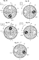
- the figure 7E thus shows an intermediate position of the plate in which the opening O is partially opposite two air inlets/outlets.
- the first transfer of air from volume V1 to volume V3 is a transfer of so-called hot air
- the second transfer of air from volume V2 to the volume V1 is a so-called cold air transfer.
- the first transfer of air from volume V1 to volume V2 is a transfer of so-called cold air
- the second transfer of air from volume V3 to volume V1 is a transfer of air says hot.
- At least a first period corresponds to a so-called hot time interval while at least a second period corresponds to a so-called cold time interval.
- the calculation means of the control and processing unit consider a period T (for example equal to one day) and determine, over this period T, the variation in temperature at which the cabinet electrical is exposed.
- the temperature variation curve can be generated by taking into account weather forecast data for the location in which the electrical cabinet is installed or from weather data obtained for the same period, a previous year, or after a learning period , or by any other means.
- the control and processing unit may in particular have access to a meteorological data server (S_MET- figure 1 ) allowing him to have the data necessary for the creation of the curve.
- control and processing unit UC is caused to apply the first operating mode MOD1.
- control and processing unit UC is caused to apply the second operating mode MOD2.
- control and processing unit UC may have to apply the third mode of operation.
- the system may include a temperature sensor TEMP (shown in the figure 1 ) connected to an input module of the control and processing unit UC and placed inside the electrical cabinet 1 in order to collect temperature measurement data.
- TEMP shown in the figure 1
- control and processing unit US can implement a regulation by comparing the temperature present in the volume V1 of the electrical cabinet with the dew point temperature.
- the system can also integrate the temperature sensor TEMP connected to an input module of the control and processing unit UC and placed inside the electrical cabinet 1 in order to collect measurement data of temperature.
- the system may include a humidity sensor connected to another input module of the control and processing unit UC in order to collect the humidity measurement data inside the electrical cabinet.
- the reservoir 21 can be made of a non-elastic (or non-extensible) material or of an extensible material.
- the pressure exerted by the walls of the reservoir 21 makes it possible to naturally release the air present in the reservoir during the second mode of operation. In this operating mode, the only fan VENT used between volume V1 and volume V2 can even be stopped.
Landscapes
- Engineering & Computer Science (AREA)
- Aviation & Aerospace Engineering (AREA)
- Physics & Mathematics (AREA)
- Thermal Sciences (AREA)
- Microelectronics & Electronic Packaging (AREA)
- Power Engineering (AREA)
- Cooling Or The Like Of Electrical Apparatus (AREA)
- Control Of Temperature (AREA)
Description
La présente invention se rapporte à un système de gestion de la température dans une enveloppe électrique.The present invention relates to a temperature management system in an electrical enclosure.
L'invention concerne également un procédé de gestion de la température mis en œuvre à l'aide dudit système.The invention also relates to a method for managing the temperature implemented using said system.
La gestion de la température dans l'enceinte d'une enveloppe électrique, telle qu'une armoire électrique ou un coffret, est u ne question traitée de manière récurrente. Les appareils présents dans l'enveloppe ont tendance à chauffer et il est donc nécessaire de maintenir la température à l'intérieur de l'enveloppe sous un certain seuil, au risque sinon de dégrader les appareils. A l'inverse, il est également possible de devoir chauffer l'espace interne de l'enveloppe lorsque l'enceinte subit des variations de températures susceptibles de créerde la condensation. C'est notamment le cas lorsque l'enveloppe est placée à l'extérieur car il peut ainsi faire très chaud pendant la journée et très froid pendant la nuit.The management of the temperature in the enclosure of an electrical enclosure, such as an electrical cabinet or a box, is a question dealt with on a recurring basis. The devices present in the enclosure tend to heat up and it is therefore necessary to maintain the temperature inside the enclosure below a certain threshold, otherwise there is a risk of degrading the devices. Conversely, it is also possible to have to heat the internal space of the enclosure when the enclosure undergoes temperature variations likely to create condensation. This is particularly the case when the envelope is placed outside because it can be very hot during the day and very cold during the night.
Pour répondre àces différentes contraintes, il est classique d'utiliser un système de ventilation pour permettre une circulation d'air dans l'enveloppe. Une solution de climatisation et/ou de chauffage peut être utilisée respectivement en remplacement ou en complément afin de réguler la température à l'intérieur de l'enveloppe.To meet these different constraints, it is conventional to use a ventilation system to allow air circulation in the envelope. An air conditioning and/or heating solution can be used respectively as a replacement or as a complement in order to regulate the temperature inside the envelope.
Cependant, ces solutions ne s'avèrent pas toujours économes en énergie.However, these solutions are not always energy efficient.
Il existe toujours un besoin de proposer une solution de gestion de la température dans une enveloppe électrique, telle qu'une armoire électrique, qui puisse fonctionner pour produiredu froid ou du chaud, qui puisse tenir compte des variations de température, parfois importantes, subies par l'enveloppe électrique, qui soit fiable, économe en énergie électrique et qui ne nécessite pas l'emploi de composants spécifiques.There is always a need to propose a solution for managing the temperature in an electrical enclosure, such as an electrical cabinet, which can operate to produce cold or heat, which can take into account the sometimes significant temperature variations undergone by the electrical enclosure, which is reliable, economical in terms of electrical energy and which does not require the use of specific components.
On connaît les documents
Ce but est atteint par un système de gestion de la température selon la revendication 1.This object is achieved by a temperature management system according to
Selon une particularité, le système comporte un troisième mode de fonctionnement dans lequel l'unité de commande et de traitement commande les premiers moyens de transfert d'air et les deuxièmes moyens de transfert d'air pour bloquer tout flux d'air respectivement entre le premier volume et le deuxième volume et entre le premier volume et le troisième volume.According to one feature, the system includes a third mode of operation in which the control and processing unit controls the first air transfer means and the second air transfer means to block any flow of air respectively between the first volume and the second volume and between the first volume and the third volume.
Selon une autre particularité, le système comporte des moyens de détermination d'une première période d'activation des premiers moyens de transfert d'air et des deuxièmes moyens de transfert d'air et d'une deuxième période d'activation des premiers moyens de transfert d'air et des deuxièmes moyens de transfert d'air.According to another feature, the system comprises means for determining a first period of activation of the first air transfer means and second air transfer means and a second period of activation of the first means of air transfer and second air transfer means.
Selon une autre particularité, la première période d'activation est définie par un premier intervalle de temps dénommé Dtc et défini par la relation suivante : ![]()
![]()
Dans laquelle :
- tcmin correspond à un premier instant correspondant à la température (Tmax - ec),
- tcmax correspond à un deuxième instant correspondant à la température (Tmax - ec),
- Tmax correspond à une valeur maximale de température subie par le système sur une période donnée et ec correspond à un premier écart de température.
- tc min corresponds to a first instant corresponding to the temperature (T max - e c ),
- tc max corresponds to a second instant corresponding to the temperature (T max - ec),
- Tmax corresponds to a maximum temperature value experienced by the system over a given period and e c corresponds to a first temperature difference.
Selon une autre particularité, la deuxième période d'activation est définie par un deuxième intervalle de temps dénommé Dtf et défini par la relation suivante : ![]()
![]()
Dans laquelle :
- tfmin correspond à un premier instant correspondant à une température (Tmin + ef),
- tfmax correspond à un deuxième instant correspondant à la température (Tmin + ef),
- Tmin correspond à une valeur minimale de température subie par le système sur ladite période donnée et et correspond à un deuxième écart de température.
- tf min corresponds to a first instant corresponding to a temperature (T min + e f ),
- tf max corresponds to a second instant corresponding to the temperature (T min + e f ),
- Tmin corresponds to a minimum temperature value experienced by the system over said given period and and corresponds to a second temperature difference.
Selon une autre particularité, le système comporte un capteur de température configurée pour fournir la valeur minimale de température et la valeur maximale de température.According to another feature, the system includes a temperature sensor configured to supply the minimum temperature value and the maximum temperature value.
Selon une autre particularité, le système comporte des moyens de connexion à un serveur de données météorologiques et des moyens d'interrogation dudit serveur pour obtenir ladite valeur minimale de température et ladite valeur maximale de température et une courbe d'évolution de la température.According to another feature, the system includes means for connecting to a meteorological data server and means for querying said server to obtain said minimum temperature value and said maximum temperature value and a temperature change curve.
Selon une autre particularité, le système comporte un capteur de température destiné à être placé dans le premier volume et en ce que l'unité de commande et de traitement comporte une entrée reliée audit capteur de température et en ce que lesdits moyens de détermination du mode de fonctionnement sont configurés pour se baser sur des données de mesure de température fournies par ledit capteur.According to another feature, the system comprises a temperature sensor intended to be placed in the first volume and in that the control and processing unit comprises an input connected to said temperature sensor and in that said means for determining the mode of operation are configured to be based on temperature measurement data provided by said sensor.
Selon une autre particularité, lesdits moyens de détermination du mode de fonctionnement comportent des moyens de comparaison de chaque donnée de température fournie par ledit capteur de température avec au moins une valeur seuil. Selon une autre particularité, lesdits moyens de détermination du mode de fonctionnement comportent des moyens de calcul de la température de rosée et en ce qu'il comporte des moyens de comparaison de chaque donnée de température fournie par ledit capteur de température avec ladite température de rosée.According to another feature, said means for determining the mode of operation comprise means for comparing each temperature datum supplied by said temperature sensor with at least one threshold value. According to another feature, said means for determining the mode of operation comprise means for calculating the dew temperature and in this that it includes means for comparing each temperature datum provided by said temperature sensor with said dew point temperature.
Selon une autre particularité, les premiers moyens de transfert d'air comportent un premier ventilateur commandé par l'unité de commande et de traitement.According to another feature, the first air transfer means comprise a first fan controlled by the control and processing unit.
Selon une autre particularité, les premiers moyens de transfert d'air comportent des moyens d'obturation de la première entrée/sortie d'air et/ou de la deuxième entrée/sortie d'air, commandés par l'unité de commande et de traitement.
Selon une autre particularité, les deuxièmes moyens de transfert d'air comportent un deuxième ventilateur commandé par l'unité de commande et de traitement.According to another feature, the first air transfer means comprise means for closing off the first air inlet/outlet and/or the second air inlet/outlet, controlled by the control unit and treatment.
According to another feature, the second air transfer means comprise a second fan controlled by the control and processing unit.
Selon une autre particularité, les deuxièmes moyens de transfert d'air comportent des moyens d'obturation de la troisième entrée/sortie d'air et/ou de la quatrième entrée/sortie d'air, commandés par l'unité de commande et de traitement.According to another feature, the second air transfer means comprise means for closing off the third air inlet/outlet and/or the fourth air inlet/outlet, controlled by the control unit and treatment.
Selon une autre particularité, les premiers moyens de transfert d'air et les deuxièmes moyens de transfert d'air comportent une platine rotative autour d'un axe, ladite platine portant un unique ventilateur et une ouverture diamétralement opposés et étant commandé par l'unité de commande et de traitement pour tourner autour de son axe entre au moins deux positions, une première position angulaire dans laquelle son ventilateur est positionné entre la première entrée/sortie d'air et la deuxième entrée sortie d'air et son ouverture est positionnée entre la troisième entrée/sortie d'air et la quatrième entrée sortie d'air et une deuxième position angulaire dans laquelle son ventilateur est positionné entre la troisième entrée/sortie d'air et la quatrième entrée/sortie d'air et son ouverture est positionnée entre la première entrée/sortie d'air et la deuxième entrée/sortie d'air.According to another feature, the first air transfer means and the second air transfer means comprise a rotating plate about an axis, said plate carrying a single diametrically opposed fan and opening and being controlled by the unit control and processing device to rotate around its axis between at least two positions, a first angular position in which its fan is positioned between the first air inlet/outlet and the second air inlet/outlet and its opening is positioned between the third air inlet/outlet and the fourth air inlet/outlet and a second angular position in which its fan is positioned between the third air inlet/outlet and the fourth air inlet/outlet and its opening is positioned between the first air inlet/outlet and the second air inlet/outlet.
Selon une autre particularité, la première position angulaire et la deuxième position angulaire sont obtenues par une rotation de la platine de 180°.
Selon une autre particularité, la platine est configurée pour prendre au moins une troisième position angulaire décalée de 90° par rapport à la première position angulaire, ladite troisième position angulaire correspondant à un mode de fonctionnement dans lequel la platine s'interpose entre la première entrée/sortie d'air et la deuxième entrée/sortie d'air pour bloquer leur liaison et la platine s'interpose entre la troisième entrée/sortie d'air et la quatrième entrée/sortie d'air pour bloquer leur liaison.According to another feature, the first angular position and the second angular position are obtained by rotating the plate through 180°.
According to another feature, the plate is configured to assume at least a third angular position offset by 90° relative to the first angular position, said third angular position corresponding to an operating mode in which the plate is interposed between the first input / air outlet and the second air inlet / outlet to block their connection and the plate is interposed between the third air inlet / outlet and the fourth air inlet / outlet to block their connection.
Selon une autre particularité, le réservoir est réalisé dans un matériau extensible.According to another feature, the reservoir is made of an extensible material.
L'invention concerne également une installation électrique comportant une enveloppe électrique qui comprend une paroi inférieure, une paroi supérieure et au moins une paroi latérale, de manière à délimiter un premier volume fermé, ladite installation comportant un système tel que défini ci-dessus qui est installé sur l'une de ses parois, la deuxième entrée/sortie d'air et la quatrième entrée/sortie d'air du système étant connectés audit premier volume.The invention also relates to an electrical installation comprising an electrical enclosure which comprises a lower wall, an upper wall and at the at least one side wall, so as to delimit a first closed volume, said installation comprising a system as defined above which is installed on one of its walls, the second air inlet/outlet and the fourth inlet/outlet system air being connected to said first volume.
L'invention concerne également un procédé de gestion de la température dans une installation électrique telle que définie ci-dessus, le procédé comportant les étapes suivantes :
- Sélection d'un mode de fonctionnement du système,
- Application dudit mode de fonctionnement sélectionné par commande des premiers moyens de transfert d'air et des deuxièmes moyens de transfert d'air.
- Selection of a system operating mode,
- Application of said operating mode selected by controlling the first air transfer means and the second air transfer means.
D'autres caractéristiques et avantages vont apparaître dans la description détaillée qui suit faite en regard des dessins annexés dans lesquels :
- La
figure 1 représente le système de gestion de la température conforme à l'invention adapté sur une armoire électrique ; - La
figure 2 représente les moyens de transfert d'air employés dans le système de l'invention ; - La
figure 3 illustre de manière schématique les échanges d'air réalisés respectivement dans le premier mode de fonctionnement et dans le deuxième mode de fonctionnement ; - Les
figures 4A, 4B ,5A, 5B ,6A, 6B illustrent les différents états de fonctionnement du système de l'invention ; - Les
figures 7A à 7E représentent un exemple de réalisation d'une partie du système de l'invention et illustrent son principe de fonctionnement ; - La
figure 8 représente par une courbe un principe de contrôle par la température du système de l'invention ;
- The
figure 1 represents the temperature management system in accordance with the invention fitted to an electrical cabinet; - The
figure 2 represents the air transfer means employed in the system of the invention; - The
picture 3 schematically illustrates the air exchanges carried out respectively in the first mode of operation and in the second mode of operation; - The
Figures 4A, 4B ,5A, 5B ,6A, 6B illustrate the different operating states of the system of the invention; - The
figures 7A to 7E represent an embodiment of part of the system of the invention and illustrate its principle of operation; - The
figure 8 represents by a curve a principle of temperature control of the system of the invention;
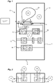
En référence à la
De manière non limitative, une armoire électrique 1 peut comporter une paroi inférieure 10, une paroi supérieure 11 et quatre parois latérales 12 opposées deux à deux. Ses parois délimitent un premier volume interne fermé V1 dans lequel sont placés des appareils électriques. Dans l'armoire électrique, les appareils électriques 13 peuvent être montés sur des supports, tels que montants et rails 14 adaptés. L'armoire 1 peut comporter une grille permettant à son volume interne d'échanger de l'air avec l'extérieur ou être complètement hermétique, notamment lorsqu'elle est destinée à être employée en extérieur. L'armoire 1 pourra être fabriqué dans un matériau métallique.In a non-limiting manner, an
De manière non limitative, le système 2 de gestion de la température conforme à l'invention peut être fixé sur la paroi supérieure 11 de l'armoire électrique.In a non-limiting way, the
De manière générale, le système 2 de gestion de la température de l'invention présente la particularité de pouvoir stocker de l'air chaud lors des périodes chaudes pour le restituer lors des périodes plus froides et de pouvoir stocker de l'air froid lors des périodes froides pour le restituer lors des périodes plus chaudes.In general, the
Pour cela, le système 2 conforme à l'invention comporte une première enceinte 20 délimitant un deuxième volume V2 fermé, distinct du volume V1 de l'armoire. Il pourra s'agir d'un caisson hermétique. Cette enceinte 20 est avantageusement réalisée dans un matériau le plus isolant possible de la chaleur de manière à limiter au maximum les échanges thermiques entre l'espace interne de cette enceinte et l'extérieur.For this, the
Le système 2 comporte également un réservoir 21 délimitant un troisième volume fermé, distinct du premier volume V1 et du deuxième volume V2. Le réservoir 21 est également réalisé dans un matériau garantissant une séparation hermétique du troisième volume V3 par rapport au deuxième volume V2.The
Le réservoir 21 est destiné à être placé dans le deuxième volume V2 de la première enceinte 20.
Le réservoir 21 est réalisé dans un matériau souple, lui permettant de faire varier son volume d'une valeur minimale pouvant être égale à zéro à une valeur maximale correspondant à celui du deuxième volume V2 délimité par l'enceinte 20. La paroi de cette enceinte 21 est avantageusement réalisée dans un matériau le plus isolant possible de la chaleur de manière à limiter au maximum les échanges thermiques avec l'espace V2.
On verra ci-après que le réservoir 21 peut également être réalisé dans un matériau extensible, type ballon de baudruche, lui permettant de se dégonfler et de libérer l'air qu'il aura préalablement stocké sous la seule pression de ses parois.It will be seen below that the
Le système 2 comporte une première entrée/sortie d'air I1 connectée au deuxième volume V2 et une deuxième entrée/sortie d'air I2 destinée à être connectée au premier volume V1 lorsque le système 2 est adapté sur l'armoire électrique 1.
Le système 2 comporte une troisième entrée/sortie d'air I3 connectée au troisième volume V3 et une quatrième entrée/sortie d'air I4 destinée à être connectée au premier volume V1 lorsque le système 2 est adapté sur l'armoire électrique 2.
Toutes les entrées/sorties d'air sont indépendantes et distinctes, c'est-à-dire qu'elles ne communiquent pas entre elles.All the air inlets/outlets are independent and separate, that is to say they do not communicate with each other.
Chaque entrée/sortie d'air peut être réalisée sous la forme d'un canal débouchant dans le volume fermé considéré.Each air inlet/outlet can be made in the form of a channel opening out into the closed volume considered.
La deuxième entrée/sortie d'air I2 et la quatrième entrée/sortie d'air I4 du système sont destinées à venir se connecter sur des ouvertures correspondantes réalisées sur une paroi de l'armoire électrique 1, par exemple la paroi supérieure 11 de celle-ci.The second air inlet/outlet I2 and the fourth air inlet/outlet I4 of the system are intended to be connected to corresponding openings made on a wall of the
Le système 2 peut comporter une goulotte 22 connectée à la quatrième entrée/sortie d'air I4, ladite goulotte 22 débouchant à l'intérieur du volume V1 de l'armoire électrique, préférentiellement de manière centrale par rapport au volume V1 de l'armoire afin de mieux diffuser/prélever l'air.The
Le système 2 comporte également des premiers moyens de transfert d'air MT1 agencés entre la première entrée/sortie d'air I1 et la deuxième entrée/sortie d'air I2 et des deuxièmes moyens de transfert d'air MT2 agencés entre la troisième entrée/sortie d'air I3 et la quatrième entrée/sortie d'air I4.The
Les premiers moyens de transfert d'air MT1 peuvent comporter au moins un ventilateur et être commandés pour permettre un transfert d'air de la première entrée/sortie d'air I1 vers la deuxième entrée/sortie d'air I2, donc du deuxième volume V2 vers le premier volume V1 lorsque le système est adapté sur l'armoire électrique 1, ou de la deuxième entrée/sortie d'air I2 vers la première entrée/sortie d'air I1, donc du premier volume V1 vers le deuxième volume V2 lorsque le système 2 est adapté sur l'armoire électrique 1.The first air transfer means MT1 may include at least one fan and be controlled to allow air transfer from the first air inlet/outlet I1 to the second air inlet/outlet I2, therefore from the second volume V2 to the first volume V1 when the system is fitted to
Les deuxièmes moyens de transfert d'air MT2 peuvent comporter au moins un ventilateur et être commandés pour permettre un transfert d'air de la troisième entrée/sortie d'air I3 vers la quatrième entrée/sortie d'air I4, donc du troisième volume V3 vers le premier volume V1 lorsque le système 2 est adapté sur l'armoire électrique 1, ou de la quatrième entrée/sortie d'air I4 vers la troisième entrée/sortie d'air I3, donc du premier volume V1 vers le troisième volume V3 lorsque le système 2 est adapté sur l'armoire électrique 1.The second air transfer means MT2 may comprise at least one fan and be controlled to allow air transfer from the third air inlet/outlet I3 to the fourth air inlet/outlet I4, therefore from the third volume V3 to the first volume V1 when
Les premiers moyens de transfert d'air MT1 peuvent comporter un premier ventilateur VENT1 agencé entre les deux sorties d'air.The first air transfer means MT1 may comprise a first fan VENT1 arranged between the two air outlets.
Les deuxièmes moyens de transfert d'air MT2 peuvent comporter un deuxième ventilateur VENT2 agencé entre les deux sorties d'air.The second air transfer means MT2 may comprise a second fan VENT2 arranged between the two air outlets.
On verra ci-après que, dans un mode de réalisation particulier de l'invention, un seul ventilateur peut être employé.It will be seen below that, in a particular embodiment of the invention, a single fan can be used.
Selon un aspect particulier de l'invention, on distingue plusieurs modes de fonctionnement possibles du système 2 :
- Premier mode de fonctionnement MOD1 : Premier transfert d'air du premier volume V1 vers le troisième volume V3 et deuxième transfert d'air simultané du deuxième volume V2 vers le premier volume V1 ;
- Deuxième mode de fonctionnement MOD2 : Premier transfert d'air du premier volume V1 vers le deuxième volume V2 et deuxième transfert d'air simultané du troisième volume V3 vers le premier volume V1.
- Troisième mode de fonctionnement MOD3 : Système fermé, c'est-à-dire aucun transfert d'air d'un volume à un autre.
- First mode of operation MOD1: First transfer of air from the first volume V1 to the third volume V3 and second simultaneous transfer of air from the second volume V2 to the first volume V1;
- Second operating mode MOD2: First transfer of air from the first volume V1 to the second volume V2 and second simultaneous transfer of air from the third volume V3 to the first volume V1.
- Third operating mode MOD3: Closed system, that is to say no transfer of air from one volume to another.
La
Le système 2 comporte une unité de commande et de traitement UC destinée à commander chaque mode de fonctionnement du système. Cette unité de commande et de traitement UC peut notamment comporter des modules d'entrées/sorties. Les premiers moyens de transfert d'air MT1 peuvent être connectés sur un premier module de sortie de l'unité de commande et de traitement UC et les deuxièmes moyens de transfert d'air MT2 peuvent être connectés sur un deuxième module de sortie de l'unité de commande et de traitement UC. On verra que l'unité de commande et de traitement UC peut comporter des moyens de calculs lui permettant de déterminer dans quelle mode de fonctionnement le système 2 doit fonctionner.The
En référence aux
En référence aux
Sur les
De manière non limitative mais particulièrement avantageuse, le système 2 peut ne fonctionner qu'avec un seul ventilateur pour les deux modes de fonctionnement MOD1, MOD2 décrits ci-dessus. Ce seul et même ventilateur VENT est en effet employé alternativement comme premiers moyens de transfert d'air MT1 ou comme deuxièmes moyens de transfert d'air MT2, selon le mode de fonctionnement du système. Ainsi, ce seul ventilateur VENT est employé dans le premier mode de fonctionnement MOD1 pour le premier transfert d'air du volume V1 vers le volume V3 et une simple et unique ouverture O est alors employée pour réaliser le deuxième transfert d'air du volume V2 vers le volume V1. Et dans le deuxième mode de fonctionnement, ce seul ventilateur VENT est employé pour le premier transfert d'air du volume V1 vers le volume V2 alors que ladite ouverture O est employée pour le deuxième transfert d'air du volume V3 vers le volume V1.In a non-limiting but particularly advantageous manner, the
Dans cette réalisation à un seul ventilateur VENT, en référence aux
Sur la
Sur la
Sur la
Sur la
La platine 23 peut être fixée sur l'axe d'un moteur électrique connecté sur un module de sortie de l'unité de commande et de traitement UC. Selon le mode de fonctionnement à appliquer, l'unité de commande et de traitement UC commande le moteur électrique pour faire tourner la platine et lui faire prendre la position angulaire désirée.The
Selon un aspect particulier de l'invention, pour réguler le débit d'air vers chaque volume, il est possible de contrôler la position de l'ouverture O réalisée sur la platine. En faisant varier la position angulaire de la platine 23 par commande du moteur, l'unité de commande et de traitement UC peut contrôler la position de l'ouverture vis-à-vis des deux entrées/sorties d'air et ainsi augmenter ou réduire le débit d'air de manière simple. Le contrôle du débit d'air peut être réalisé par l'unité de commande et de traitement en tenant compte de différents paramètres (mode de fonctionnement appliqué, température(s), défaut de fonctionnement,...). La
Selon un aspect particulier de l'invention, dans le premier mode de fonctionnement, le premier transfert d'air du volume V1 vers le volume V3 est un transfert d'air dit chaud, tandis que le deuxième transfert d'air du volume V2 vers le volume V1 est un transfert d'air dit froid.According to a particular aspect of the invention, in the first mode of operation, the first transfer of air from volume V1 to volume V3 is a transfer of so-called hot air, while the second transfer of air from volume V2 to the volume V1 is a so-called cold air transfer.
Dans le deuxième mode de fonctionnement, le premier transfert d'air du volume V1 vers le volume V2 est un transfert d'air dit froid, tandis que le deuxième transfert d'air du volume V3 vers le volume V1 est un transfert d'air dit chaud.In the second operating mode, the first transfer of air from volume V1 to volume V2 is a transfer of so-called cold air, while the second transfer of air from volume V3 to volume V1 is a transfer of air says hot.
Chaque mode de fonctionnement peut être commandé selon différentes variantes de réalisations exposées ci-dessous.Each mode of operation can be controlled according to different variant embodiments set out below.
Dans une première variante de réalisation, il s'agit de définir plusieurs périodes de temps de fonctionnement du système. Au moins une première période correspond à un intervalle de temps dit chaud alors que au moins une deuxième période correspond à un intervalle de temps dit froid.In a first embodiment variant, it is a question of defining several operating time periods of the system. At least a first period corresponds to a so-called hot time interval while at least a second period corresponds to a so-called cold time interval.
Pour définir chacune des deux périodes, les moyens de calcul de l'unité de commande et de traitement considèrent une période T (par exemple égale à une journée) et détermine, sur cette période T, la variation de la température à laquelle l'armoire électrique est exposée. La courbe de variation de température peut être générée en tenant compte des données de prévision météorologiques du lieu dans lequel l'armoire électrique est implantée ou à partir de données météorologiques obtenues pour la même période, une année précédente, ou après une période d'apprentissage, ou par tout autre moyen. L'unité de commande et de traitement peut notamment disposer d'un accès à un serveur de données météorologiques (S_MET-
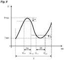
Un exemple de courbe de variation de la température sur cette période T est représenté sur la
Sur la période T et à partir de la courbe, on peut voir que la température augmente jusqu'à atteindre une valeur maximale Tmax pour ensuite diminuer jusqu'à atteindre une valeur minimale Tmin. L'amplitude de température sur cette période est donc de Tmax - Tmin.Over the period T and from the curve, it can be seen that the temperature increases until it reaches a maximum value Tmax and then decreases until it reaches a minimum value Tmin. The temperature amplitude over this period is therefore Tmax - Tmin.
Pour définir les intervalles de temps froids et chauds, les moyens de calcul procèdent de la manière ci-dessous.
- On définit :
- Dtf : intervalle de temps froid = tfmax - tfmin
- Dtc : intervalle de temps chaud = tcmax - tcmin
- Avec :
- tcmin : premier instant correspondant à une température (Tmax - ec)
- tcmax : deuxième instant correspondant à une température (Tmax - ec)
- tfmin : premier instant correspondant à une température (Tmin + ec)
- tfmax : deuxième instant correspondant à une température (Tmin + ec) et :
- ec, et : paramètres réglables correspondant à des écarts de température permettant d'englober la valeur maximale et la valeur minimale dans un intervalle de temps donné ;
- We define :
- Dtf: cold time interval = tf max - tf min
- Dtc: hot time interval = tc max - tc min
- With :
- tc min : first instant corresponding to a temperature (T max - e c )
- tc max : second instant corresponding to a temperature (T max - e c )
- tf min : first instant corresponding to a temperature (T min + e c )
- tf max : second instant corresponding to a temperature (T min + e c ) and:
- e c , and: adjustable parameters corresponding to temperature differences making it possible to include the maximum value and the minimum value in a given time interval;
De manière non limitative, on pourra définir que (Tmax - ec) correspond à une température maximale de fonctionnement des appareils et que (Tmin + ef) correspond à une température minimale de fonctionnement des appareils.In a non-limiting way, it will be possible to define that (Tmax − e c ) corresponds to a maximum operating temperature of the devices and that (Tmin + e f ) corresponds to a minimum operating temperature of the devices.
Pendant l'intervalle de temps chaud calculé, l'unité de commande et de traitement UC est amenée à appliquer le premier mode de fonctionnement MOD1.During the calculated hot time interval, the control and processing unit UC is caused to apply the first operating mode MOD1.
Pendant l'intervalle de temps froid, l'unité de commande et de traitement UC est amenée à appliquer le deuxième mode de fonctionnement MOD2.During the cold weather interval, the control and processing unit UC is caused to apply the second operating mode MOD2.
Dans toute autre situation, l'unité de commande et de traitement UC peut être amenée à appliquer le troisième mode de fonctionnement.In any other situation, the control and processing unit UC may have to apply the third mode of operation.
Dans une deuxième variante de réalisation, l'unité de commande et de traitement UC applique le mode de fonctionnement adapté en tenant compte de la température mesurée à l'intérieur de l'armoire électrique 1, donc à l'intérieur du volume V1. Dans ce cas, il s'agit d'un principe de régulation de température. Ainsi, l'unité de commande et de traitement UC peut fonctionner de la manière suivante :
- Si la température mesurée est supérieure à une valeur seuil prédéfinie, l'unité de commande et de traitement déclenche le premier mode de fonctionnement afin de transférer de l'air froid dans le volume V1 de l'armoire et donc refroidir les appareils électriques.
- Si la température mesurée est inférieure à une valeur seuil prédéfinie, l'unité de commande et de traitement déclenche le deuxième mode de fonctionnement afin de transférer de l'air chaud dans le volume V1 de l'armoire et donc de réchauffer l'intérieur de l'armoire électrique.
- If the measured temperature is greater than a predefined threshold value, the control and processing unit triggers the first mode of operation in order to transfer cold air into the volume V1 of the cabinet and therefore cool the electrical appliances.
- If the measured temperature is lower than a predefined threshold value, the control and processing unit triggers the second mode of operation in order to transfer hot air into the volume V1 of the cabinet and therefore to heat the interior of the cabinet. the electrical cabinet.
Dans cette dernière réalisation, le système peut comporter un capteur de température TEMP (représenté sur la
Dans une réalisation particulière, pendant un intervalle froid, l'unité de commande et de traitement US peut mettre en œuvre une régulation en comparant la température présente dans le volume V1 de l'armoire électrique avec la température de rosée.In a particular embodiment, during a cold interval, the control and processing unit US can implement a regulation by comparing the temperature present in the volume V1 of the electrical cabinet with the dew point temperature.
Pour rappel, la température de rosée se calcule à partir de la relation suivante : 
Pendant l'intervalle froid, les moyens de calcul de l'unité de commande et de traitement comparent la température détermine la température de rosée pour chaque valeur mesurée de température dans le volume V1 de l'armoire électrique puis compare chaque valeur mesurée avec la température de rosée correspondante :
- Si la valeur mesurée de température est inférieure à la température de rosée calculée, l'unité de commande et de traitement UC applique le deuxième mode de fonctionnement MOD2 jusqu'à ce que la température mesurée devienne supérieure à la température de rosée correspondante, ceci afin d'éliminer le possible condensat.
- Si la valeur mesurée de température est supérieure à la température de rosée calculée, il n'y a pas de risque de formation de condensat et donc l'unité de commande et de traitement UC ne force aucun mode de fonctionnement, c'est-à-dire que aucun transfert d'air n'est commandé entre les volumes.
- If the measured temperature value is lower than the calculated dew point temperature, the control and processing unit UC applies the second operating mode MOD2 until the measured temperature becomes higher than the corresponding dew point temperature, this in order to to eliminate possible condensate.
- If the measured temperature value is higher than the calculated dew point temperature, there is no risk of condensate formation and therefore the control and processing unit UC does not force any operating mode, i.e. say that no air transfer is controlled between the volumes.
Dans cette réalisation, le système peut également intégrer le capteur de température TEMP connecté sur un module d'entrée de l'unité de commande et de traitement UC et placé à l'intérieur de l'armoire électrique 1 afin de recueillir des données de mesure de température. Pour déterminer la température de rosée, le système peut comporter un capteur d'humidité connecté sur un autre module d'entrée de l'unité de commande et de traitement UC afin de recueillir les données de mesure d'humidité à l'intérieur de l'armoire électrique.In this embodiment, the system can also integrate the temperature sensor TEMP connected to an input module of the control and processing unit UC and placed inside the
Selon différents aspects particuliers, comme déjà évoqué ci-dessus, le réservoir 21 peut être réalisé dans un matériau non élastique (ou non extensible) ou dans un matériau extensible. Dans ce dernier cas, la pression exercée par les parois du réservoir 21 permet de libérer naturellement l'air présent dans le réservoir lors du deuxième mode de fonctionnement. Dans ce mode de fonctionnement, le seul ventilateur VENT employé entre le volume V1 et le volume V2 peut même être arrêté.According to various particular aspects, as already mentioned above, the
La solution de l'invention présente ainsi de nombreux avantages, parmi lesquels :
- Elle est simple à mettre en œuvre et est adaptable aisément sur une armoire électrique existante ;
- Elle n'utilise que des solutions classiques de ventilation pour fonctionner ;
- Elle permet de s'adapter facilement aux conditions de température externes ;
- It is simple to implement and is easily adaptable to an existing electrical cabinet;
- It only uses conventional ventilation solutions to operate;
- It makes it easy to adapt to external temperature conditions;
Claims (20)
- Temperature management system (2), that can be adapted to an electrical enclosure, said electrical enclosure delimiting a first volume (V1) that is closed with respect to the outside, said system being characterized in that it comprises:- a first chamber (20) delimiting a second closed volume (V2) and a tank (21) housed in said first chamber (20) and delimiting a third closed volume (V3) inside said first chamber, distinct from the second volume (V2),- first air transfer means (MT1) arranged between a first air inlet/outlet (11) connected to the second volume (V2) and a second air inlet/outlet (12) intended to be connected to the first volume (V1),- second air transfer means (MT2) arranged between a third air inlet/outlet (13) connected to the third volume (V3) and a fourth air inlet/outlet (14) intended to be connected to the first volume (V1),- a control and processing unit (UC) comprising a first command output connected to said first air transfer means, a second command output connected to said second air transfer means and means for determining a mode of operation of said system, said mode of operation being chosen from among at least:- a first mode of operation (MOD1) in which the control and processing unit (UC) controls the first air transfer means for generating a first air flow from the second volume (V2) to said first volume (V1) and the second air transfer means for generating a second air flow from the first volume (V1) to said third volume (V3),- a second mode of operation (MOD2) in which the control and processing unit controls the first air transfer means for generating a first air flow from the first volume (V1) to said second volume (V2) and the second air transfer means for generating a second air flow from said third volume (V3) to said first volume (V1),- the temperature management system (2) having the particular feature of being able to store hot air during hot periods to restore it in colder periods and of being able to store cold air during cold periods to restore it in hotter periods,- in the first mode of operation, the first air transfer from the volume V1 to the volume V3 being a so-called hot air transfer, whereas the second air transfer from the volume V2 to the volume V1 is a so-called cold air transfer,- in the second mode of operation, the first air transfer from the volume V1 to the volume V2 is a so-called cold air transfer, whereas the second air transfer from the volume V3 to the volume V1 is a so-called hot air transfer; and- the tank (21) being made from a flexible material.
- System according to Claim 1, characterized in that it comprises a third mode of operation (MOD3) in which the control and processing unit (UC) controls the first air transfer means and the second air transfer means to block any air flow respectively between the first volume and the second volume and between the first volume and the third volume.
- System according to Claim 1 or 2, characterized in that it comprises means for determining a first period of activation of the first air transfer means (MT1) and of the second air transfer means (MT2) and a second period of activation of the first air transfer means (MT1) and of the second air transfer means (MT2).
- System according to Claim 3, characterized in that the first activation period is defined by a first time interval named Dtc and defined by the following relationship:
 - tcmin corresponds to a first instant corresponding to the temperature (Tmax - ec),- tcmax corresponds to a second instant corresponding to the temperature (Tmax - ec),- Tmax corresponds to a maximum temperature value sustained by the system over a given period and ec corresponds to a first temperature difference.
 - System according to Claim 3 or 4, characterized in that the second activation period is defined by a second time interval named Dtf and defined by the following relationship:
 - tfmin corresponds to a first instant corresponding to a temperature (Tmin + ef),- tfmax corresponds to a second instant corresponding to the temperature (Tmin + ef),- Tmin corresponds to a minimum temperature value sustained by the system over said given period and ef corresponds to a second temperature difference.
 - System according to Claim 4 or 5, characterized in that it comprises a temperature sensor (TEMP) configured to supply the minimum temperature value and the maximum temperature value.
- System according to one of Claims 4 to 6, characterized in that it comprises means for connecting to a meteorological data server and means for interrogating said server to obtain said minimum temperature value and said maximum temperature value and a temperature trend curve.
- System according to Claim 1 or 2, characterized in that it comprises a temperature sensor (TEMP) intended to be placed in the first volume and in that the control and processing unit (UC) comprises an input linked to said temperature sensor and in that said means for determining the mode of operation are configured to be based on temperature measurement data supplied by said sensor.
- System according to Claim 8, characterized in that said means for determining the mode of operation comprise means for comparing each temperature datum supplied by said temperature sensor (TEMP) with at least one threshold value.
- System according to Claim 8 or 9, characterized in that said means for determining the mode of operation comprise means for calculating the dew point temperature and in that it comprises means for comparing each temperature datum supplied by said temperature sensor (TEMP) with said dew point temperature.
- System according to one of Claims 1 to 10, characterized in that the first air transfer means (MT1) comprise a first fan (VENT1) controlled by the control and processing unit.
- System according to one of Claims 1 to 11, characterized in that the first air transfer means (MT1) comprise means for blocking the first air inlet/outlet and/or the second air inlet/outlet controlled by the control and processing unit.
- System according to one of Claims 1 to 12, characterized in that the second air transfer means (MT2) comprise a second fan (VENT2) controlled by the control and processing unit.
- System according to one of Claims 1 to 13, characterized in that the second air transfer means (MT2) comprise means for blocking the third air inlet/outlet and/or the fourth air inlet/outlet, controlled by the control and processing unit.
- System according to one of Claims 1 to 10, characterized in that the first air transfer means (MT1) and the second air transfer means (MT2) comprise a plate (23) that rotates about an axis, said plate bearing a single fan (VENT) and an aperture (O) that are diametrically opposite and being controlled by the control and processing unit (UC) to revolve about its axis between at least two positions, a first angular position in which its fan (VENT) is positioned between the first air inlet/outlet (11) and the second air inlet/outlet (12) and its aperture (O) is positioned between the third air inlet/outlet (13) and the fourth air inlet/outlet (14) and a second angular position in which its fan (VENT) is positioned between the third air inlet/outlet (13) and the fourth air inlet/outlet (14) and its aperture (O) is positioned between the first air inlet/outlet (11) and the second air inlet/outlet (12).
- System according to Claim 15, characterized in that the first angular position and the second angular position are obtained by a rotation of the plate (23) of 180°.
- System according to Claim 15 or 16, characterized in that the plate (23) is configured to take at least one third angular position that is offset by 90° with respect to the first angular position, said third angular position corresponding to a mode of operation in which the plate (23) is interposed between the first air inlet/outlet (11) and the second air inlet/outlet (12) to block the linking thereof and the plate (23) is interposed between the third air inlet/outlet (13) and the fourth air inlet/outlet (14) to block the linking thereof.
- System according to one of Claims 1 to 17, characterized in that the tank (21) is made from an extendable material.
- Electrical installation comprising an electrical enclosure which comprises a bottom wall (10), a top wall (11) and at least one side wall (12), so as to delimit a first closed volume (V1), characterized in that the installation comprises a system (2) as defined in one of Claims 1 to 18 which is installed on one of its walls, the second air inlet/outlet (12) and the fourth air inlet/outlet (14) of the system being connected to said first volume (V1).
- Method for managing the temperature in an electrical installation as defined in Claim 19, characterized in that it comprises the following steps:- selection of a mode of operation of the system,- application of said selected mode of operation by control of the first air transfer means (MT1) and of the second air transfer means (MT2).
Applications Claiming Priority (1)
| Application Number | Priority Date | Filing Date | Title |
|---|---|---|---|
| FR1872311A FR3089384B1 (en) | 2018-12-04 | 2018-12-04 | Temperature management system in an electrical enclosure |
Publications (2)
| Publication Number | Publication Date |
|---|---|
| EP3664588A1 EP3664588A1 (en) | 2020-06-10 |
| EP3664588B1 true EP3664588B1 (en) | 2023-01-11 |
Family
ID=66049309
Family Applications (1)
| Application Number | Title | Priority Date | Filing Date |
|---|---|---|---|
| EP19207752.7A Active EP3664588B1 (en) | 2018-12-04 | 2019-11-07 | System for managing the temperature in an electric envelope |
Country Status (4)
| Country | Link |
|---|---|
| US (1) | US11495944B2 (en) |
| EP (1) | EP3664588B1 (en) |
| ES (1) | ES2938684T3 (en) |
| FR (1) | FR3089384B1 (en) |
Family Cites Families (10)
| Publication number | Priority date | Publication date | Assignee | Title |
|---|---|---|---|---|
| US6877551B2 (en) * | 2002-07-11 | 2005-04-12 | Avaya Technology Corp. | Systems and methods for weatherproof cabinets with variably cooled compartments |
| DE102005011179B4 (en) * | 2005-03-09 | 2007-07-26 | Rittal Gmbh & Co. Kg | Method for monitoring the cooling operation in a device arrangement with a receiving housing, in particular a control cabinet and with a cooling device |
| GB2464354B (en) * | 2009-03-13 | 2011-06-08 | 4Energy Ltd | Equipment enclosure |
| FR2983676B1 (en) * | 2011-12-05 | 2013-12-20 | Schneider Electric Ind Sas | ELECTRICAL CABINET WITH IMPROVED THERMAL DISSIPATION |
| FR3003408B1 (en) * | 2013-03-12 | 2016-09-23 | Schneider Electric Ind Sas | ELECTRICAL CABINET WITH IMPROVED THERMAL DISSIPATION |
| US10015914B2 (en) * | 2015-02-05 | 2018-07-03 | Vertiv Energy Systems, Inc. | Enclosures and methods of managing heat in heat generating modules |
| FR3036233B1 (en) * | 2015-05-11 | 2018-06-01 | Schneider Electric Industries Sas | THERMAL DISSIPATION SYSTEM FOR ELECTRICAL ENVELOPE |
| FR3047328B1 (en) * | 2016-01-29 | 2018-01-05 | Schneider Electric Industries Sas | METHOD AND SYSTEM FOR DETERMINING THE LEVEL OF EFFICIENCY OF A VENTILATION SYSTEM OF AN ELECTRICAL ENVELOPE |
| US10524382B2 (en) * | 2017-08-28 | 2019-12-31 | Dmytro KHACHATUROV | System and method for forced air cooling of electrical device |
| FR3089704B1 (en) * | 2018-12-07 | 2020-11-27 | Schneider Electric Ind Sas | Ventilation unit for electrical cabinet |
-
2018
- 2018-12-04 FR FR1872311A patent/FR3089384B1/en active Active
-
2019
- 2019-11-07 EP EP19207752.7A patent/EP3664588B1/en active Active
- 2019-11-07 ES ES19207752T patent/ES2938684T3/en active Active
- 2019-11-26 US US16/695,312 patent/US11495944B2/en active Active
Also Published As
| Publication number | Publication date |
|---|---|
| FR3089384B1 (en) | 2020-10-30 |
| US20200176958A1 (en) | 2020-06-04 |
| EP3664588A1 (en) | 2020-06-10 |
| RU2019139043A (en) | 2021-06-03 |
| ES2938684T3 (en) | 2023-04-13 |
| FR3089384A1 (en) | 2020-06-05 |
| US11495944B2 (en) | 2022-11-08 |
Similar Documents
| Publication | Publication Date | Title |
|---|---|---|
| EP2779335B1 (en) | Electrical cabinet with improved heat dissipation | |
| EP3467605B1 (en) | Method for monitoring a temperature control system associated with an electrical cabinet | |
| EP3195917A1 (en) | Air filtering system for an electrical enclosure | |
| EP2553345B1 (en) | Device for analyzing the thermal behaviour in transient regime of a room equipped with a heating or air-conditioning unit | |
| FR3025871B1 (en) | EQUIPMENT FOR MONITORING AT LEAST ONE THERMAL CONTROL APPARATUS, AND ASSOCIATED CONTROL ARRANGEMENT AND CONTROL SYSTEM | |
| EP3090240B1 (en) | Method and device for determining the heat loss coefficient of a room | |
| EP3664588B1 (en) | System for managing the temperature in an electric envelope | |
| EP3090112B1 (en) | Method for operating a window and a home automation of a building | |
| EP3739273A1 (en) | Room ventilation system | |
| WO2013102578A2 (en) | Thermal analysis device | |
| FR2878619A1 (en) | Wet clutch`s plate e.g. pressure plate, temperature estimating method for vehicle`s automatic transmission, involves correcting thermodynamic equations by estimating error functions from measured and calculated oil temperatures difference | |
| WO2009156649A1 (en) | Computer bay comprising an adaptive cooling device | |
| FR3036233A1 (en) | THERMAL DISSIPATION SYSTEM FOR ELECTRICAL ENVELOPE | |
| EP3078827B1 (en) | Method for diagnosing an opening or closing position of a valve of a cooling circuit of an engine of a vehicle | |
| EP0852331A1 (en) | Method and apparatus for measuring the volumetric heat loss coefficient of an electrically heated room | |
| FR2739931A1 (en) | Method for measuring the thermal loss volume coefficient of an electrically heated building. | |
| EP3358323A1 (en) | Estimation of the thermal resistance of a building | |
| FR2489958A1 (en) | TEMPERATURE PROBE WITH THERMOELECTRIC CONVERTER AND USE THEREOF | |
| EP3630556B1 (en) | Device for controlling and regulating a windscreen wiper blade heating circuit | |
| FR2463371A1 (en) | Fluid flowmeter for solar heater - senses both illumination level and working fluid temp. to reduce heat losses by control of working fluid circulation | |
| FR3012613A1 (en) | METHOD FOR CONFIGURING A PULSE READING AND RECORDING DEVICE FOR READING AT LEAST ONE PULSE EMITTING COUNTER AND ASSOCIATED DEVICE | |
| EP2979146B1 (en) | Control device for a heating, ventilation and air-conditioning machine | |
| CH342010A (en) | Method for integrating the heat absorption capacity of a medium and apparatus for carrying out this method | |
| FR2930055A1 (en) | POWER BALANCING METHOD OF A HEATING DEVICE | |
| EP2051369A2 (en) | Method for determining an internal magnitude of an actuator for manoeuvring a mobile home-automation element |
Legal Events
| Date | Code | Title | Description |
|---|---|---|---|
| PUAI | Public reference made under article 153(3) epc to a published international application that has entered the european phase |
Free format text: ORIGINAL CODE: 0009012 |
|
| STAA | Information on the status of an ep patent application or granted ep patent |
Free format text: STATUS: THE APPLICATION HAS BEEN PUBLISHED |
|
| AK | Designated contracting states |
Kind code of ref document: A1 Designated state(s): AL AT BE BG CH CY CZ DE DK EE ES FI FR GB GR HR HU IE IS IT LI LT LU LV MC MK MT NL NO PL PT RO RS SE SI SK SM TR |
|
| AX | Request for extension of the european patent |
Extension state: BA ME |
|
| STAA | Information on the status of an ep patent application or granted ep patent |
Free format text: STATUS: REQUEST FOR EXAMINATION WAS MADE |
|
| 17P | Request for examination filed |
Effective date: 20200721 |
|
| RBV | Designated contracting states (corrected) |
Designated state(s): AL AT BE BG CH CY CZ DE DK EE ES FI FR GB GR HR HU IE IS IT LI LT LU LV MC MK MT NL NO PL PT RO RS SE SI SK SM TR |
|
| GRAP | Despatch of communication of intention to grant a patent |
Free format text: ORIGINAL CODE: EPIDOSNIGR1 |
|
| STAA | Information on the status of an ep patent application or granted ep patent |
Free format text: STATUS: GRANT OF PATENT IS INTENDED |
|
| RIC1 | Information provided on ipc code assigned before grant |
Ipc: H02B 1/56 20060101ALI20220906BHEP Ipc: H05K 7/20 20060101AFI20220906BHEP |
|
| INTG | Intention to grant announced |
Effective date: 20220923 |
|
| GRAS | Grant fee paid |
Free format text: ORIGINAL CODE: EPIDOSNIGR3 |
|
| GRAA | (expected) grant |
Free format text: ORIGINAL CODE: 0009210 |
|
| STAA | Information on the status of an ep patent application or granted ep patent |
Free format text: STATUS: THE PATENT HAS BEEN GRANTED |
|
| AK | Designated contracting states |
Kind code of ref document: B1 Designated state(s): AL AT BE BG CH CY CZ DE DK EE ES FI FR GB GR HR HU IE IS IT LI LT LU LV MC MK MT NL NO PL PT RO RS SE SI SK SM TR |
|
| REG | Reference to a national code |
Ref country code: GB Ref legal event code: FG4D Free format text: NOT ENGLISH |
|
| REG | Reference to a national code |
Ref country code: CH Ref legal event code: EP |
|
| REG | Reference to a national code |
Ref country code: DE Ref legal event code: R096 Ref document number: 602019024243 Country of ref document: DE |
|
| REG | Reference to a national code |
Ref country code: IE Ref legal event code: FG4D Free format text: LANGUAGE OF EP DOCUMENT: FRENCH |
|
| REG | Reference to a national code |
Ref country code: AT Ref legal event code: REF Ref document number: 1544183 Country of ref document: AT Kind code of ref document: T Effective date: 20230215 |
|
| REG | Reference to a national code |
Ref country code: ES Ref legal event code: FG2A Ref document number: 2938684 Country of ref document: ES Kind code of ref document: T3 Effective date: 20230413 |
|
| REG | Reference to a national code |
Ref country code: LT Ref legal event code: MG9D |
|
| REG | Reference to a national code |
Ref country code: NL Ref legal event code: MP Effective date: 20230111 |
|
| REG | Reference to a national code |
Ref country code: AT Ref legal event code: MK05 Ref document number: 1544183 Country of ref document: AT Kind code of ref document: T Effective date: 20230111 |
|
| PG25 | Lapsed in a contracting state [announced via postgrant information from national office to epo] |
Ref country code: NL Free format text: LAPSE BECAUSE OF FAILURE TO SUBMIT A TRANSLATION OF THE DESCRIPTION OR TO PAY THE FEE WITHIN THE PRESCRIBED TIME-LIMIT Effective date: 20230111 |
|
| PG25 | Lapsed in a contracting state [announced via postgrant information from national office to epo] |
Ref country code: RS Free format text: LAPSE BECAUSE OF FAILURE TO SUBMIT A TRANSLATION OF THE DESCRIPTION OR TO PAY THE FEE WITHIN THE PRESCRIBED TIME-LIMIT Effective date: 20230111 Ref country code: PT Free format text: LAPSE BECAUSE OF FAILURE TO SUBMIT A TRANSLATION OF THE DESCRIPTION OR TO PAY THE FEE WITHIN THE PRESCRIBED TIME-LIMIT Effective date: 20230511 Ref country code: NO Free format text: LAPSE BECAUSE OF FAILURE TO SUBMIT A TRANSLATION OF THE DESCRIPTION OR TO PAY THE FEE WITHIN THE PRESCRIBED TIME-LIMIT Effective date: 20230411 Ref country code: LV Free format text: LAPSE BECAUSE OF FAILURE TO SUBMIT A TRANSLATION OF THE DESCRIPTION OR TO PAY THE FEE WITHIN THE PRESCRIBED TIME-LIMIT Effective date: 20230111 Ref country code: LT Free format text: LAPSE BECAUSE OF FAILURE TO SUBMIT A TRANSLATION OF THE DESCRIPTION OR TO PAY THE FEE WITHIN THE PRESCRIBED TIME-LIMIT Effective date: 20230111 Ref country code: HR Free format text: LAPSE BECAUSE OF FAILURE TO SUBMIT A TRANSLATION OF THE DESCRIPTION OR TO PAY THE FEE WITHIN THE PRESCRIBED TIME-LIMIT Effective date: 20230111 Ref country code: AT Free format text: LAPSE BECAUSE OF FAILURE TO SUBMIT A TRANSLATION OF THE DESCRIPTION OR TO PAY THE FEE WITHIN THE PRESCRIBED TIME-LIMIT Effective date: 20230111 |
|
| PG25 | Lapsed in a contracting state [announced via postgrant information from national office to epo] |
Ref country code: SE Free format text: LAPSE BECAUSE OF FAILURE TO SUBMIT A TRANSLATION OF THE DESCRIPTION OR TO PAY THE FEE WITHIN THE PRESCRIBED TIME-LIMIT Effective date: 20230111 Ref country code: PL Free format text: LAPSE BECAUSE OF FAILURE TO SUBMIT A TRANSLATION OF THE DESCRIPTION OR TO PAY THE FEE WITHIN THE PRESCRIBED TIME-LIMIT Effective date: 20230111 Ref country code: IS Free format text: LAPSE BECAUSE OF FAILURE TO SUBMIT A TRANSLATION OF THE DESCRIPTION OR TO PAY THE FEE WITHIN THE PRESCRIBED TIME-LIMIT Effective date: 20230511 Ref country code: GR Free format text: LAPSE BECAUSE OF FAILURE TO SUBMIT A TRANSLATION OF THE DESCRIPTION OR TO PAY THE FEE WITHIN THE PRESCRIBED TIME-LIMIT Effective date: 20230412 Ref country code: FI Free format text: LAPSE BECAUSE OF FAILURE TO SUBMIT A TRANSLATION OF THE DESCRIPTION OR TO PAY THE FEE WITHIN THE PRESCRIBED TIME-LIMIT Effective date: 20230111 |
|
| REG | Reference to a national code |
Ref country code: DE Ref legal event code: R097 Ref document number: 602019024243 Country of ref document: DE |
|
| PG25 | Lapsed in a contracting state [announced via postgrant information from national office to epo] |
Ref country code: SM Free format text: LAPSE BECAUSE OF FAILURE TO SUBMIT A TRANSLATION OF THE DESCRIPTION OR TO PAY THE FEE WITHIN THE PRESCRIBED TIME-LIMIT Effective date: 20230111 Ref country code: RO Free format text: LAPSE BECAUSE OF FAILURE TO SUBMIT A TRANSLATION OF THE DESCRIPTION OR TO PAY THE FEE WITHIN THE PRESCRIBED TIME-LIMIT Effective date: 20230111 Ref country code: EE Free format text: LAPSE BECAUSE OF FAILURE TO SUBMIT A TRANSLATION OF THE DESCRIPTION OR TO PAY THE FEE WITHIN THE PRESCRIBED TIME-LIMIT Effective date: 20230111 Ref country code: DK Free format text: LAPSE BECAUSE OF FAILURE TO SUBMIT A TRANSLATION OF THE DESCRIPTION OR TO PAY THE FEE WITHIN THE PRESCRIBED TIME-LIMIT Effective date: 20230111 Ref country code: CZ Free format text: LAPSE BECAUSE OF FAILURE TO SUBMIT A TRANSLATION OF THE DESCRIPTION OR TO PAY THE FEE WITHIN THE PRESCRIBED TIME-LIMIT Effective date: 20230111 |
|
| PLBE | No opposition filed within time limit |
Free format text: ORIGINAL CODE: 0009261 |
|
| STAA | Information on the status of an ep patent application or granted ep patent |
Free format text: STATUS: NO OPPOSITION FILED WITHIN TIME LIMIT |
|
| PG25 | Lapsed in a contracting state [announced via postgrant information from national office to epo] |
Ref country code: SK Free format text: LAPSE BECAUSE OF FAILURE TO SUBMIT A TRANSLATION OF THE DESCRIPTION OR TO PAY THE FEE WITHIN THE PRESCRIBED TIME-LIMIT Effective date: 20230111 |
|
| 26N | No opposition filed |
Effective date: 20231012 |
|
| PGFP | Annual fee paid to national office [announced via postgrant information from national office to epo] |
Ref country code: ES Payment date: 20231219 Year of fee payment: 5 |
|
| PG25 | Lapsed in a contracting state [announced via postgrant information from national office to epo] |
Ref country code: SI Free format text: LAPSE BECAUSE OF FAILURE TO SUBMIT A TRANSLATION OF THE DESCRIPTION OR TO PAY THE FEE WITHIN THE PRESCRIBED TIME-LIMIT Effective date: 20230111 |
|
| PGFP | Annual fee paid to national office [announced via postgrant information from national office to epo] |
Ref country code: IT Payment date: 20231124 Year of fee payment: 5 Ref country code: FR Payment date: 20231123 Year of fee payment: 5 |
|
| REG | Reference to a national code |
Ref country code: DE Ref legal event code: R119 Ref document number: 602019024243 Country of ref document: DE |
|
| REG | Reference to a national code |
Ref country code: CH Ref legal event code: PL |
|
| PG25 | Lapsed in a contracting state [announced via postgrant information from national office to epo] |
Ref country code: MC Free format text: LAPSE BECAUSE OF FAILURE TO SUBMIT A TRANSLATION OF THE DESCRIPTION OR TO PAY THE FEE WITHIN THE PRESCRIBED TIME-LIMIT Effective date: 20230111 |
|
| PG25 | Lapsed in a contracting state [announced via postgrant information from national office to epo] |
Ref country code: LU Free format text: LAPSE BECAUSE OF NON-PAYMENT OF DUE FEES Effective date: 20231107 |
|
| PG25 | Lapsed in a contracting state [announced via postgrant information from national office to epo] |
Ref country code: CH Free format text: LAPSE BECAUSE OF NON-PAYMENT OF DUE FEES Effective date: 20231130 |
|
| GBPC | Gb: european patent ceased through non-payment of renewal fee |
Effective date: 20231107 |
|
| PG25 | Lapsed in a contracting state [announced via postgrant information from national office to epo] |
Ref country code: MC Free format text: LAPSE BECAUSE OF FAILURE TO SUBMIT A TRANSLATION OF THE DESCRIPTION OR TO PAY THE FEE WITHIN THE PRESCRIBED TIME-LIMIT Effective date: 20230111 Ref country code: LU Free format text: LAPSE BECAUSE OF NON-PAYMENT OF DUE FEES Effective date: 20231107 Ref country code: CH Free format text: LAPSE BECAUSE OF NON-PAYMENT OF DUE FEES Effective date: 20231130 |
|
| REG | Reference to a national code |
Ref country code: BE Ref legal event code: MM Effective date: 20231130 |
|
| REG | Reference to a national code |
Ref country code: IE Ref legal event code: MM4A |
|
| PG25 | Lapsed in a contracting state [announced via postgrant information from national office to epo] |
Ref country code: IE Free format text: LAPSE BECAUSE OF NON-PAYMENT OF DUE FEES Effective date: 20231107 Ref country code: DE Free format text: LAPSE BECAUSE OF NON-PAYMENT OF DUE FEES Effective date: 20240601 |
|
| PG25 | Lapsed in a contracting state [announced via postgrant information from national office to epo] |
Ref country code: GB Free format text: LAPSE BECAUSE OF NON-PAYMENT OF DUE FEES Effective date: 20231107 |
|
| PG25 | Lapsed in a contracting state [announced via postgrant information from national office to epo] |
Ref country code: BE Free format text: LAPSE BECAUSE OF NON-PAYMENT OF DUE FEES Effective date: 20231130 |