EP3664430A1 - Vibratory device and optical detection device - Google Patents
Vibratory device and optical detection device Download PDFInfo
- Publication number
- EP3664430A1 EP3664430A1 EP18893643.9A EP18893643A EP3664430A1 EP 3664430 A1 EP3664430 A1 EP 3664430A1 EP 18893643 A EP18893643 A EP 18893643A EP 3664430 A1 EP3664430 A1 EP 3664430A1
- Authority
- EP
- European Patent Office
- Prior art keywords
- flange portion
- support body
- cover
- vibration device
- light
- Prior art date
- Legal status (The legal status is an assumption and is not a legal conclusion. Google has not performed a legal analysis and makes no representation as to the accuracy of the status listed.)
- Granted
Links
Images






Classifications
-
- B—PERFORMING OPERATIONS; TRANSPORTING
- B06—GENERATING OR TRANSMITTING MECHANICAL VIBRATIONS IN GENERAL
- B06B—METHODS OR APPARATUS FOR GENERATING OR TRANSMITTING MECHANICAL VIBRATIONS OF INFRASONIC, SONIC, OR ULTRASONIC FREQUENCY, e.g. FOR PERFORMING MECHANICAL WORK IN GENERAL
- B06B1/00—Methods or apparatus for generating mechanical vibrations of infrasonic, sonic, or ultrasonic frequency
- B06B1/02—Methods or apparatus for generating mechanical vibrations of infrasonic, sonic, or ultrasonic frequency making use of electrical energy
- B06B1/0207—Driving circuits
-
- B—PERFORMING OPERATIONS; TRANSPORTING
- B06—GENERATING OR TRANSMITTING MECHANICAL VIBRATIONS IN GENERAL
- B06B—METHODS OR APPARATUS FOR GENERATING OR TRANSMITTING MECHANICAL VIBRATIONS OF INFRASONIC, SONIC, OR ULTRASONIC FREQUENCY, e.g. FOR PERFORMING MECHANICAL WORK IN GENERAL
- B06B1/00—Methods or apparatus for generating mechanical vibrations of infrasonic, sonic, or ultrasonic frequency
- B06B1/02—Methods or apparatus for generating mechanical vibrations of infrasonic, sonic, or ultrasonic frequency making use of electrical energy
- B06B1/06—Methods or apparatus for generating mechanical vibrations of infrasonic, sonic, or ultrasonic frequency making use of electrical energy operating with piezoelectric effect or with electrostriction
- B06B1/0644—Methods or apparatus for generating mechanical vibrations of infrasonic, sonic, or ultrasonic frequency making use of electrical energy operating with piezoelectric effect or with electrostriction using a single piezoelectric element
- B06B1/0651—Methods or apparatus for generating mechanical vibrations of infrasonic, sonic, or ultrasonic frequency making use of electrical energy operating with piezoelectric effect or with electrostriction using a single piezoelectric element of circular shape
-
- B—PERFORMING OPERATIONS; TRANSPORTING
- B08—CLEANING
- B08B—CLEANING IN GENERAL; PREVENTION OF FOULING IN GENERAL
- B08B7/00—Cleaning by methods not provided for in a single other subclass or a single group in this subclass
- B08B7/02—Cleaning by methods not provided for in a single other subclass or a single group in this subclass by distortion, beating, or vibration of the surface to be cleaned
-
- B—PERFORMING OPERATIONS; TRANSPORTING
- B08—CLEANING
- B08B—CLEANING IN GENERAL; PREVENTION OF FOULING IN GENERAL
- B08B7/00—Cleaning by methods not provided for in a single other subclass or a single group in this subclass
- B08B7/04—Cleaning by methods not provided for in a single other subclass or a single group in this subclass by a combination of operations
-
- G—PHYSICS
- G02—OPTICS
- G02B—OPTICAL ELEMENTS, SYSTEMS OR APPARATUS
- G02B27/00—Optical systems or apparatus not provided for by any of the groups G02B1/00 - G02B26/00, G02B30/00
- G02B27/0006—Optical systems or apparatus not provided for by any of the groups G02B1/00 - G02B26/00, G02B30/00 with means to keep optical surfaces clean, e.g. by preventing or removing dirt, stains, contamination, condensation
-
- G—PHYSICS
- G03—PHOTOGRAPHY; CINEMATOGRAPHY; ANALOGOUS TECHNIQUES USING WAVES OTHER THAN OPTICAL WAVES; ELECTROGRAPHY; HOLOGRAPHY
- G03B—APPARATUS OR ARRANGEMENTS FOR TAKING PHOTOGRAPHS OR FOR PROJECTING OR VIEWING THEM; APPARATUS OR ARRANGEMENTS EMPLOYING ANALOGOUS TECHNIQUES USING WAVES OTHER THAN OPTICAL WAVES; ACCESSORIES THEREFOR
- G03B17/00—Details of cameras or camera bodies; Accessories therefor
-
- G—PHYSICS
- G03—PHOTOGRAPHY; CINEMATOGRAPHY; ANALOGOUS TECHNIQUES USING WAVES OTHER THAN OPTICAL WAVES; ELECTROGRAPHY; HOLOGRAPHY
- G03B—APPARATUS OR ARRANGEMENTS FOR TAKING PHOTOGRAPHS OR FOR PROJECTING OR VIEWING THEM; APPARATUS OR ARRANGEMENTS EMPLOYING ANALOGOUS TECHNIQUES USING WAVES OTHER THAN OPTICAL WAVES; ACCESSORIES THEREFOR
- G03B17/00—Details of cameras or camera bodies; Accessories therefor
- G03B17/02—Bodies
-
- G—PHYSICS
- G03—PHOTOGRAPHY; CINEMATOGRAPHY; ANALOGOUS TECHNIQUES USING WAVES OTHER THAN OPTICAL WAVES; ELECTROGRAPHY; HOLOGRAPHY
- G03B—APPARATUS OR ARRANGEMENTS FOR TAKING PHOTOGRAPHS OR FOR PROJECTING OR VIEWING THEM; APPARATUS OR ARRANGEMENTS EMPLOYING ANALOGOUS TECHNIQUES USING WAVES OTHER THAN OPTICAL WAVES; ACCESSORIES THEREFOR
- G03B17/00—Details of cameras or camera bodies; Accessories therefor
- G03B17/02—Bodies
- G03B17/08—Waterproof bodies or housings
-
- G—PHYSICS
- G03—PHOTOGRAPHY; CINEMATOGRAPHY; ANALOGOUS TECHNIQUES USING WAVES OTHER THAN OPTICAL WAVES; ELECTROGRAPHY; HOLOGRAPHY
- G03B—APPARATUS OR ARRANGEMENTS FOR TAKING PHOTOGRAPHS OR FOR PROJECTING OR VIEWING THEM; APPARATUS OR ARRANGEMENTS EMPLOYING ANALOGOUS TECHNIQUES USING WAVES OTHER THAN OPTICAL WAVES; ACCESSORIES THEREFOR
- G03B17/00—Details of cameras or camera bodies; Accessories therefor
- G03B17/56—Accessories
-
- H—ELECTRICITY
- H04—ELECTRIC COMMUNICATION TECHNIQUE
- H04N—PICTORIAL COMMUNICATION, e.g. TELEVISION
- H04N23/00—Cameras or camera modules comprising electronic image sensors; Control thereof
- H04N23/50—Constructional details
- H04N23/52—Elements optimising image sensor operation, e.g. for electromagnetic interference [EMI] protection or temperature control by heat transfer or cooling elements
-
- H—ELECTRICITY
- H04—ELECTRIC COMMUNICATION TECHNIQUE
- H04N—PICTORIAL COMMUNICATION, e.g. TELEVISION
- H04N23/00—Cameras or camera modules comprising electronic image sensors; Control thereof
- H04N23/50—Constructional details
- H04N23/54—Mounting of pick-up tubes, electronic image sensors, deviation or focusing coils
-
- B—PERFORMING OPERATIONS; TRANSPORTING
- B06—GENERATING OR TRANSMITTING MECHANICAL VIBRATIONS IN GENERAL
- B06B—METHODS OR APPARATUS FOR GENERATING OR TRANSMITTING MECHANICAL VIBRATIONS OF INFRASONIC, SONIC, OR ULTRASONIC FREQUENCY, e.g. FOR PERFORMING MECHANICAL WORK IN GENERAL
- B06B2201/00—Indexing scheme associated with B06B1/0207 for details covered by B06B1/0207 but not provided for in any of its subgroups
- B06B2201/70—Specific application
- B06B2201/77—Atomizers
-
- B—PERFORMING OPERATIONS; TRANSPORTING
- B60—VEHICLES IN GENERAL
- B60S—SERVICING, CLEANING, REPAIRING, SUPPORTING, LIFTING, OR MANOEUVRING OF VEHICLES, NOT OTHERWISE PROVIDED FOR
- B60S1/00—Cleaning of vehicles
- B60S1/02—Cleaning windscreens, windows or optical devices
- B60S1/56—Cleaning windscreens, windows or optical devices specially adapted for cleaning other parts or devices than front windows or windscreens
-
- G—PHYSICS
- G01—MEASURING; TESTING
- G01S—RADIO DIRECTION-FINDING; RADIO NAVIGATION; DETERMINING DISTANCE OR VELOCITY BY USE OF RADIO WAVES; LOCATING OR PRESENCE-DETECTING BY USE OF THE REFLECTION OR RERADIATION OF RADIO WAVES; ANALOGOUS ARRANGEMENTS USING OTHER WAVES
- G01S7/00—Details of systems according to groups G01S13/00, G01S15/00, G01S17/00
- G01S7/02—Details of systems according to groups G01S13/00, G01S15/00, G01S17/00 of systems according to group G01S13/00
- G01S7/027—Constructional details of housings, e.g. form, type, material or ruggedness
-
- G—PHYSICS
- G01—MEASURING; TESTING
- G01S—RADIO DIRECTION-FINDING; RADIO NAVIGATION; DETERMINING DISTANCE OR VELOCITY BY USE OF RADIO WAVES; LOCATING OR PRESENCE-DETECTING BY USE OF THE REFLECTION OR RERADIATION OF RADIO WAVES; ANALOGOUS ARRANGEMENTS USING OTHER WAVES
- G01S7/00—Details of systems according to groups G01S13/00, G01S15/00, G01S17/00
- G01S7/48—Details of systems according to groups G01S13/00, G01S15/00, G01S17/00 of systems according to group G01S17/00
- G01S7/481—Constructional features, e.g. arrangements of optical elements
- G01S7/4811—Constructional features, e.g. arrangements of optical elements common to transmitter and receiver
- G01S7/4813—Housing arrangements
-
- H—ELECTRICITY
- H04—ELECTRIC COMMUNICATION TECHNIQUE
- H04N—PICTORIAL COMMUNICATION, e.g. TELEVISION
- H04N23/00—Cameras or camera modules comprising electronic image sensors; Control thereof
- H04N23/50—Constructional details
- H04N23/55—Optical parts specially adapted for electronic image sensors; Mounting thereof
Definitions
- the present invention relates to a vibration device for removing foreign matters such as water droplets, dust or the like adhering to a dome-shaped cover, and an optical detection device including the vibration device.
- Patent Document 1 a tabular hood is arranged in front of a camera.
- a piezoelectric vibrator is fixed to the hood. Water droplets adhering to an outer surface of the hood are atomized and removed by vibration of the piezoelectric vibrator.
- Patent Document 2 described below discloses a dome-shaped light-transmissive body arranged in front of a camera.
- the dome-shaped light-transmissive body is provided with a flange portion extending outward in a radial direction.
- a ring-shaped piezoelectric vibrator is fixed to the flange portion.
- the dome-shaped light-transmissive body is vibrated by vibration of the piezoelectric vibrator. Droplets are thereby removed.
- Patent Documents 1 and 2 the water droplets or the like are removed by using the vibration of the piezoelectric vibrator.
- the tubular hood is vibrated. Therefore, there was no vibration node in a field of view of the camera.
- Patent Document 2 when a dome-shaped light-transmissive body is vibrated, it was not possible to prevent a node of vibration from being generated within the field of view of the camera. At the node of the vibration, displacement is very small. Therefore, attached water droplets or the like cannot be reliably removed.
- An object of the present invention is to provide a vibration device and an optical detection device including the vibration device capable of reliably removing water droplets or dust adhering to a surface of a dome-shaped cover.
- a first vibration device includes a dome-shaped cover arranged so as to include a detection region of an optical detection element, a tubular support body having an interior space for arranging the optical detection element and being connected to the cover, a vibrating body coupled to the support body and vibrating the cover with the support body interposed between the vibrating body and the cover, and a drive circuit, in a case where the cover and the support body are vibrated at substantially the same resonant frequency, in a connection portion where the cover and the support body are connected, the drive circuit driving the vibrating body at substantially the same frequency as the resonant frequency so as to vibrate the cover and the support body in a vibration mode in which displacement of a portion on a connection portion side of the cover and displacement of a portion on a connection portion side of the support body are in opposite directions.
- a second vibration device includes a dome-shaped cover arranged so as to include a detection region of an optical detection element, a tubular support body having an interior space for arranging the optical detection element and being connected to the cover, a vibrating body coupled to the support body and vibrating the cover with the support body interposed between the vibrating body and the cover, and a drive circuit, in a case where the cover and the support body are vibrated at substantially the same resonant frequency, the drive circuit driving the vibrating body at substantially the same frequency as the resonant frequency of the support body and the cover in a manner such that a node region is located at a connection portion where the cover and the support body are connected to each other.
- the first vibration device and the second vibration device will be collectively referred to as a vibration device according to the present invention.
- An optical detection device includes a vibration device according to the present invention, and an optical detection element arranged in at least a part of an interior space of the support body of the vibration device and having the detection region on the cover.
- a dome-shaped cover is used, but in a case where the dome-shaped cover is vibrated by a vibrating body, water droplets, dust or the like adhering to a dome-shaped cover surface can be reliably removed.
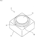
- Fig. 1 is a perspective view illustrating an appearance of an optical detection device according to a first embodiment of the present invention
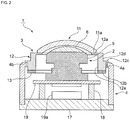
- Fig. 2 is a front cross-sectional view thereof
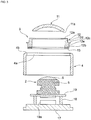
- Fig. 3 is an exploded front cross-sectional view.
- a camera module 1 as an optical detection device includes a camera module main body 2, a vibration device 3, and a case 4.
- the camera module main body 2 includes an imaging element 5 and a lens module 6 as an optical detection element.
- the vibration device 3 includes a light-transmissive body 11 as a dome-shaped cover, a tubular support body 12, and a vibrating body 13.
- the imaging element 5 of the camera module main body 2 takes an image of an outside of the light-transmissive body 11. Therefore, in this embodiment, the imaging element 5 as an optical detection element detects visible light as an active energy ray, and takes an image within a field of view as a detection region.
- the field of view which is a detection region of the imaging element 5, is located in the light-transmissive body 11. That is, the light-transmissive body 11 is made to have a size including the field of view.
- the light-transmissive body 11 is made of a transparent material.
- a transparent material is not particularly limited, and various kinds of glass such as soda glass, quartz glass, borosilicate glass and the like, and synthetic resin can be used.
- the light-transmissive body 11 has a shape obtained by cutting a part of a sphere at a position not a maximum outer peripheral portion of the sphere.
- the light-transmissive body 11 may have various curved shapes that project toward an object side, that is, toward outside. That is, an outer surface of the light-transmissive body 11 is not limited to a part of a spherical surface.
- the shape of a "dome shape" is intended to include even a shape in which planes of a plurality of polygonal shapes or the like are gathered together to have a resulting dome shape, as well as a shape formed by only a curved surface.
- an end surface on a dome-shaped support body 12 side is not limited to an annular shape, but may have a shape in which a part of the annular shape falls off, or may be an angular-annular shape.
- a ring-shaped end face 11a located in the vicinity of an outer peripheral edge of the light-transmissive body 11 is joined to a ring-shaped first end surface 12a of the support body 12.
- the support body 12 is a substantially cylindrical member and has the first end surface 12a and a second end surface 12b on the opposite side.
- a vibrating body 13 made of a piezoelectric element is joined to a second end surface 12b of the support body 12.
- the support body 12 has a fixing flange portion 12c projecting outward.
- the fixing flange portion 12c is provided at a position between the first end surface 12a and the second end surface 12b.
- the light-transmissive body 11 is vibrated with the support body 12 interposed therebetween.
- water droplets, dust or the like adhering to the outer surface of the light-transmissive body 11 can be removed.
- the support body 12 may be made of various metal materials such as stainless steel, kovar, invar, alloy thereof or the like, or ceramics such as alumina, and the material thereof is not particularly limited.
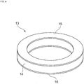
- the vibrating body 13 includes a ring-shaped piezoelectric body 14, a first excitation electrode 15 provided on one surface of the piezoelectric body 14, and a second excitation electrode 16 provided on another surface.
- the piezoelectric body 14 is subjected to poling treatment in a thickness direction.
- a piezoelectric material configuring the piezoelectric body 14 is also not particularly limited, and a SrBaTi-based piezoelectric material, a TiBaO-based piezoelectric material, a PbTiO-based piezoelectric material, or the like can be used.
- the first and second excitation electrodes 15 and 16 are made of an appropriate metal material such as Al, Cu, Ag, Au, an alloy thereof, or the like.
- the case 4 has an opening 4a opened upward.
- a ring-shaped end surface 4b is located so as to surround the opening 4a.
- a fixing flange portion 12c of the support body 12 of the vibration device 3 is joined to the ring-shaped end surface 4b.
- the vibration device 3 is fixed to the case 4.
- a portion on a lens module side of the camera module main body 2 is located in an interior space of the vibration device 3, and the remaining portion thereof is located in an interior space of the case 4.
- the entire camera module main body 2 may be located in an interior space of the support body 12. That is, it is sufficient that at least a part of the camera module main body 2 may be located in the interior space of the support body 12.
- the case 4 may also be made of a suitable material such as metal, synthetic resin, ceramics, or the like.
- case 4 is fixed to a base plate 17.
- a plurality of leg portions 18 is fixed on the base plate 17.
- a substrate 19 is fixed on the plurality of leg portions 18.
- the camera module main body 2 is fixed on the substrate 19.
- a drive circuit 19a for driving the vibrating body 13 made of a piezoelectric element and a drive circuit for driving the camera module main body 2 are provided on at least one main surface of the substrate 19 or on a top surface of the base plate 17.
- the drive circuit 19a may be configured by a suitable electric circuit capable of driving the vibrating body 13 at a specific frequency.
- the drive circuit 19a vibrates the vibrating body 13 to vibrate the light-transmissive body 11 with the support body 12 interposed therebetween.
- the drive circuit drives the vibrating body 13 at substantially the same frequency as the resonant frequency in a manner such that the light-transmissive body 11 and the support body 12 are vibrated in a vibration mode in which displacement of a portion on a connection portion side of the light-transmissive body 11 and displacement of a portion on a connection portion side of the support body 12 are in opposite directions.
- the drive circuit 19a is configured to drive the vibrating body 13 at substantially the same frequency as the resonant frequency of the light-transmissive body 11 and the support body 12 in a manner such that a node region is located at the connection portion connecting the light-transmissive body 11 and the support body 12.
- the base plate 17, the leg portion 18, and the substrate 19 can be also made of a suitable material such as synthetic resin, metal, or the like.
- the feature of this embodiment is that in the vibration device 3, in the connection portion connecting the light-transmissive body 11 and the tubular support body 12, the vibrating body 13 is driven by the drive circuit 19a at substantially the same frequency as the above-described resonant frequency in a manner such that the light-transmissive body 11 and the support body 12 are vibrated in the vibration mode in which the displacement of the portion on the connection portion side of the light-transmissive body 11 and the displacement of the portion on the connection portion side of the support body 12 are in the opposite directions.
- the vibrating body 13 including a piezoelectric vibrator is vibrated, the light-transmissive body 11 vibrates with the support body 12 interposed therebetween, but there is no portion where displacement directions on both sides are opposed to each other on a surface of the light-transmissive body 11, and the node region is located at the connection portion, therefore, a node is not present on the outer surface of the light-transmissive body 11. Therefore, the attached water droplets and dust can be reliably removed.
- a displacement amount of the light-transmissive body 11 and a displacement amount of the support body 12 are substantially the same.
- substantially the same is not necessarily intended to be absolutely the same, and not only a case where they are completely the same but also a case where the displacement amount of the support body 12 is within the displacement amount +40 to -70% of the light-transmissive body 11. Within this range, water droplets and dust adhering to the outer surface of the light-transmissive body 11 can be removed more reliably.
- the resonant frequency of the light-transmissive body 11 is substantially the same as the resonant frequency of the support body 12 to which the vibrating body 13 is coupled.
- the light-transmissive body 11 can be strongly vibrated. Therefore, water droplets and dust adhering to the outer surface of the light-transmissive body 11 can be reliably removed.
- the fact that "the resonant frequencies are substantially the same” means not only a case where the resonant frequencies are completely the same but also a case of the range in which the resonant frequency of the support body 12 is within ⁇ 10% resonant frequency of the light-transmissive body 11.
- a preferred ratio between the resonant frequency of the light-transmissive body 11 and the resonant frequency of the support body 12 will be described in more detail later with reference to Fig. 8 and Fig. 9 .
- connection portion between the light-transmissive body 11 and the support body 12 is not limited to a joint surface between the two, but is referred to as a portion on the support body 12 side which includes a boundary between the two.
- the range of the connection portion is referred to as a portion from the first end surface 12a of the support body 12 to a midpoint between the first end surface 12a and the second end surface 12b. That is, it is sufficient that the node region of the vibration may be located in this portion.
- a portion of the first end surface 12a side of the support body 12, that is, a portion closer to the first end surface 12a side than the node becomes a portion displaced in the displacement direction of the light-transmissive body 11, and a portion lower than the node becomes a portion made to be displaced in a direction opposite to the displacement direction of the light-transmissive body 11.
- the support body 12 has a cancellation part where a portion displaced in the displacement direction of the transmissive body 11 and a portion displaced in the opposite direction to the displacement direction of the light-transmissive body 11 are adjacent to each other.
- the node is the cancellation part. In this manner, it is sufficient that the cancellation part may be present in the connection portion, and the cancellation part is not limited to an interface between the light-transmissive body 11 and the support body 12.
- the node region When the node region is located in the support body 12 as described above, displacement of the node region on one side and displacement on the opposite side are in opposite directions. Whereby, the node region configures the cancellation part.
- the node region includes not only a node but also a region in the vicinity of the node.
- the node may be located in the support body 12 as described above, as long as there is no cancellation part adjacent to the displacement portion in the opposite direction.
- an outer diameter of a second portion 12e below the fixing flange portion 12c is larger than an outer diameter of a first portion 12d from the first end surface 12a side to the fixing flange portion 12c.
- the second portion 12e projects outward to configure even the flange portion.
- the flange portion projecting outward may be provided on the support body 12 separately from the fixing flange portion 12c.
- Fig. 5(a) is a schematic cross-sectional view illustrating displacement distribution in a case where the above-described light-transmissive body 11 is vibrated alone
- Fig. 5(b) is a schematic cross-sectional view illustrating displacement distribution of a structure in which the support body 12 and the vibrating body 13 are coupled to each other.
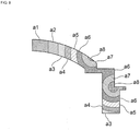
- a region a1 marked with cross-hatching indicates the largest displacement, and regions a2, a3, a4, a5, a6, and a7 respectively have smaller displacement in this order.
- a region a8 indicated by dot hatching has the smallest displacement, and corresponds to a node.
- the tubular support body 12 vibrates in a respiration mode. That is, the displacement in a direction in which the outer diameter increases and the displacement in a direction in which the outer diameter decreases are repeated. Therefore, the most displaced portion is the region a1.
- the displacement of the arrow in the region a1 is applied to the light-transmissive body 11.
- Fig. 6 is a schematic cross-sectional view illustrating displacement distribution of each part in a case where the vibrating body 13 is vibrated in a structure in which the light-transmissive body 11 is connected to the support body 12 and integrated, as in this embodiment.
- a simulation model and conditions for which the displacement distribution is obtained are as follows. Dimensions of respective portions were set to values shown in Fig. 7 .
- a material of the light-transmissive body 11 was quartz glass.
- a material of the support body 12 was stainless steel (SUS304).
- the piezoelectric element configuring the vibrating body 13 was set to have a structure in which electrodes are provided on both surfaces of a ring-shaped member made of PZT. It is assumed that the piezoelectric element was polarized in the thickness direction. Further, the resonance was analyzed under a condition in which a potential difference of 1 V was applied to front and back surfaces of the piezoelectric element.
- the region a1 is the largest displacement portion. That is, the center of the light-transmissive body 11 is displaced most greatly.
- the region a8 having the smallest displacement which becomes the node of the vibration is located on the support body 12 side from a joint interface between the two. This is because, in a case where the light-transmissive body 11 and the support body 12 are vibrated at substantially the same resonant frequency, the connection portion having a structure in which the light-transmissive body 11 and the support body 12 are connected to each other is vibrated in the vibration mode in which the displacement of a portion on the connection portion side of the light-transmissive body 11 and the displacement of a portion on the connection portion side of the support body 12 are in the opposite directions.
- the vibration can be obtained by setting the frequency at which the vibrating body 13 is driven by the drive circuit 19a to substantially the same frequency as the above-described resonant frequency in the structure in which the above-described light-transmissive body 11 and the support body 12 are connected to each other.
- Fig. 8 is a diagram illustrating displacement distribution in a case where the resonant frequency of the light-transmissive body 11 is the same as the resonant frequency of the support body 12.
- a ratio of the resonant frequency of the support body 12 with respect to the resonant frequency of the light-transmissive body 11 is defined as a resonant frequency ratio.
- the displacement distribution in a case where the resonant frequency ratio is 1.0 is illustrated.
- Fig. 9 illustrates the displacement distribution in a case where the above-described resonant frequency ratio is 1.2. Simulation conditions for the displacement distributions illustrated in Fig. 8 and Fig. 9 were the same as those in the case where the displacement distribution illustrated in Fig. 6 was obtained.
- Fig. 8 and Fig. 9 schematically illustrate the displacement distribution of the cross-sectional portion cut out into half along the center as a symmetry of a structure in which the light-transmissive body 11 and the support body 12 are connected to each other.
- regions having different magnitudes of displacement are hatched and distinguished.
- the region a1 indicates a portion where the displacement is largest, and the displacement becomes smaller in the order of the regions a2, a3, a4, a5, a6, a7, and a8.
- a viewing angle in a case where an image is taken by an imaging element as an optical detection element is an angle formed between a virtual line connecting the center of the imaging element and one node region, and a virtual line connecting the node region located on the opposite side and the center of the imaging element.
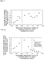
- Fig. 10 is a diagram indicating a change in viewing angle in a case where the above-described resonant frequency ratio is changed. As is apparent from Fig. 10 , it is understood that when the resonant frequency ratio exceeds 1.1, the viewing angle decreases as the resonant frequency ratio increases. On the other hand, when the viewing angle is equal to or less than 1.1, a large viewing angle of equal to or more than 163° can be obtained.
- Fig. 11 is a diagram indicating a change in a maximum displacement amount ratio of the light-transmissive body 11 in a case where the above described resonant frequency ratio is changed.
- the maximum displacement amount ratio of the light-transmissive body 11 refers to a ratio of the maximum displacement amount of the light-transmissive body 11 with respect to the maximum displacement amount of the light-transmissive body 11 in a case where the resonant frequency ratio is 1.
- the maximum displacement amount is the displacement amount of the center because the center of the light-transmissive body 11 is displaced most greatly.
- the resonant frequency ratio is preferably equal to or more than 0.9. Accordingly, it is understood that the above-described resonant frequency ratio is preferably equal to or more than 0.9 and equal to or less than 1.1.
- Fig. 12 indicates the above-described resonant frequency ratio and a change in the displacement amount ratio between the support body 12 and the light-transmissive body 11 at the connection portion.
- the displacement amount ratio in the connection portion between the support body 12 and the light-transmissive body 11 is equal to or more than 0.3 and equal to or less than 1.38.
- the resonant frequency ratio is preferably equal to or more than 0.9 and equal to or less than 1.1. In other words, it is sufficient that the resonant frequency of the support body 12 may be within the resonant frequency ⁇ 10% of the light-transmissive body 11, and this range is substantially the same frequency range as the resonant frequency of the light-transmissive body 11 as described above.
- the tubular support body 32 is connected to the light-transmissive body 11 on a side of a first end surface 32a.
- the vibrating body 13 including a ring-shaped piezoelectric element is fixed to a second end surface 32b.
- the support body 32 has a groove 32c on its inner peripheral surface.
- the groove 32c is provided between the first end surface 32a and the second end surface 32b. Since the groove 32c is provided, a first inward projecting portion 32d is provided on an upper side of the groove 32c, and a second inward projecting portion 32e is provided on a lower side of the groove 32c.
- An outer portion of the groove 32c is a coupling portion 32f,and couples the first inward projecting portion 32d and the second inward projecting portion 32e. Therefore, in a cross section extending from the above-described support body 32 toward the light-transmissive body 11, the support body 32 has a U-like shape.
- first inward projecting portion 32d and the second inward projecting portion 32e project inwardly in an annular shape from the coupling portion 32f as a reference, in this specification, such a portion projecting inward in a radial direction is also referred to as a flange portion. That is, the first inward projecting portion 32d and the second inward projecting portion 32e are first and second flange portions projecting inward in the radial direction, respectively.
- the first inward projecting portion 32d side is vibrated more strongly, and thus the light-transmissive body 11 can be vibrated more strongly.
- the first inward projecting portion 32d and the second inward projecting portion 32e are separated from each other with a space therebetween.
- the first inward projecting portion 32d can be vibrated more strongly.
- a dimension connecting an inner peripheral edge and an outer peripheral edge of the first inward projecting portion 32d be the same as a dimension connecting an inner peripheral edge and an outer peripheral edge of the second inward projecting portion 32e.
- a distance between the first inward projecting portion 32d and the second inward projecting portion 32e is preferably smaller than the dimension connecting the inner peripheral edge and the outer peripheral edge of the first inward projecting portion 32d.
- the cancellation part is a portion where a portion where the support body is displaced in the displacement direction of the light-transmissive body 11 and a portion where the support body is displaced in the opposite direction to the displacement direction of the light-transmissive body 11 are adjacent to each other.
- the cancellation part includes the first inward projecting portion 32d as the first flange portion and the second inward projecting portion 32e as the second flange portion. In the cancellation part, the first flange portion and the second flange portion are opposed to each other.
- the vibrating body 13 can be provided inside in the radial direction as compared with the first embodiment. That is, an outer diameter of the support body 32 can be reduced, thereby making it possible to reduce the size of the support body.
- a volume of the support body 32 can be reduced by about 50% compared with the first embodiment.
- the resonant frequency of the above-described support body 32 is substantially the same as the resonant frequency of the light-transmissive body 11. Then, by driving the vibrating body 13 by a drive circuit with a resonant frequency substantially the same as the above-described resonant frequency, in the connection portion, the light-transmissive body 11 and the support body 32 can be vibrated in a vibration mode in which displacement of a portion on the connection portion side of the light-transmissive body 11 and displacement of a portion on the connection portion side of the support body 32 are in opposite directions. Therefore, similarly to the first embodiment, a node of the vibration is not present in the portion located within the field of view of the light-transmissive body 11. Therefore, water droplets, dust or the like adhering to the outer surface of the light-transmissive body 11 can be reliably removed.
- Fig. 16 is a front cross-sectional view of a vibration device of a third embodiment
- Fig. 17 is a schematic cross-sectional view illustrating displacement distribution thereof.
- the vibration device 41 of the third embodiment has a structure in which a support body 42 is further jointed to a lower surface of the vibrating body 13 of the vibration device 31 of the second embodiment.
- the support body 42 is made of a tubular body, and has a first end surface 42a and a second end surface 42b as an open end surface.
- the ring-shaped first end surface 42a is joined to the vibrating body 13.
- a groove 42c is provided on an outer peripheral surface, in the opposite case of the support body 32.
- a first flange portion 42d is provided above the groove 42c
- a second flange portion 42e is provided below the groove 42c
- a bottom portion of the groove 42c becomes a coupling portion 42f coupling the first flange portion 42d and the second flange portion 42e.
- the first flange portion in the support body 32 and the second flange portion 42e in the support body 42 are provided so as to project in opposite directions to the respective coupling portions.
- the first flange portion 42d in the support body 42 and the second flange portion in the support body 32 are also provided so as to project in opposite directions to the respective coupling portions.
- the second support body 42 may be further joined under the vibrating body 13 made of the piezoelectric element.
- a resonant frequency relationship between the support body 32 and the light-transmissive body 11 and the frequency for driving the vibrating body 13 by the drive circuit are the same as those in the first and second embodiments. Therefore, water droplets, dust or the like adhering to the outer surface of the light-transmissive body 11 can be reliably removed.
- the vibration device 41 when the vibrating body 13 is vibrated, the first support body 32 and the second support body 42 are displaced in the opposite directions. Therefore, the displacement in the opposite directions to each other in the vibrating body 13 including piezoelectric elements are canceled out, so that deformation of the vibrating body 13 can be reduced as illustrated in Fig. 17 .
- the vibration device 41 of the third embodiment it has been confirmed that the maximum displacement amount in the piezoelectric element is reduced to about 0.75 times as compared with the vibration device 31 of the second embodiment. Therefore, the stress applied to the piezoelectric element is reduced, so that breakage or deterioration of the piezoelectric element at the time of repeated use is less likely to occur. Therefore, the reliability can be enhanced.
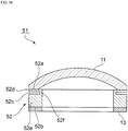
- Fig. 18 is a front cross-sectional view of a vibration device according to a fourth embodiment.
- a groove 52c is provided on an outer peripheral surface of a support body 52. That is, the support body 52 has a structure similar to that of the second support body 42 in the third embodiment.
- a portion between the groove 52c and a first end surface 52a is a first flange portion 52d.
- a portion between the groove 52c and a second end surface 52b is a second flange portion 52e.
- the first flange portion 52d and the second flange portion 52e are coupled to each other by a coupling portion 52f located at a bottom portion of the groove 52c. That is, when the coupling portion 52f is used as a reference, the first flange portion 52d and the second flange portion 52e configure a flange portion projecting outward in the radial direction.
- a cross-sectional shape of the support body 52 made of a tubular body may have a U-shape that is open toward the outside, contrary to the vibration device 31 of the second embodiment.
- Fig. 19 is a front cross-sectional view of a vibration device according to a fifth embodiment.
- a support body 62 made of a tubular body has a groove 62c opened toward an outside on an inner peripheral surface and a groove 62g opened toward an inner side on the inner peripheral surface.
- a first end surface 62a which is a first ring-shaped opening end surface, is jointed to the light-transmissive body 11.
- the groove 62g is located between the first end surface 62a and the groove 62c. Therefore, a first flange portion 62d above the groove 62c and a second flange portion 62e on the lower side are coupled by a coupling portion 62f.
- the vibrating body 13 is joined to a second end surface 62b which is a lower surface of the second flange portion 62e. That is, based on the outer surface of the coupling portion 62f at a bottom portion of the groove 62c, the first and second flange portions 62d and 62e are annular flange portions projecting outward in the radial direction.
- a flange portion 62h above the groove 62g is coupled to the first flange portion 62d by a coupling portion 62i. Therefore, in a case where the groove 62g is centered, when the flange portion 62h is defined as the first flange portion, the first flange portion 62d serves as the second flange portion.
- the flange portion 62h projecting inward in the radial direction and the first and second flange portions 62d and 62e projecting outward in the radial direction are provided.
- the first flange portion and the second flange portion are provided so as to project in the opposite direction to the coupling portion. Therefore, the support body 62 has an S-shape in a cross section orthogonal to a circumferential direction of the support body 62, that is, in a cross section including a direction from the support body 62 toward the light-transmissive body 11. As illustrated in Fig. 19 , the first flange portion 62d is opposed to the flange portion 62h and the second flange portion 62e with a space therebetween.
- the support body 62 in this embodiment includes a cancellation part having the flange portion 62h and the first flange portion 62d, and a cancellation part including the first flange portion 62d and the second flange portion 62e.
- deformation is suppressed in the first flange portion 62d, similar to the vibrating body 13 of the third embodiment.
- Fig. 20 is a front cross-sectional view of a vibration device of a sixth embodiment.
- a support body 72 has a groove 72c opened toward the outside on the side closer to a first end surface 72a in contrast to the support body 62 illustrated in Fig. 19 , and has a groove 72g opened toward the inside on the side closer to a second end surface 72b than the groove 72c.
- a first flange portion 62d, the coupling portion 62f, the second flange portion 62e, the coupling portion 62i, and a flange portion 72h projecting toward the inside are coupled in this order from the first end surface 72a side.
- the cross section of the support body 72 is formed in an inverted S-shape, in other words, in a Z-shape.
- the second flange portion 62e is opposed to the flange portion 72h and the first flange portion 62d with a space interposed therebetween. Even in this case, in the same manner as in the vibration device 61, when the vibrating body 13 is vibrated, the light-transmissive body 11 can be strongly vibrated.
- the resonant frequency of the support body 62 or the support body 72 is substantially the same as the resonant frequency of the light-transmissive body 11 and the vibrating body 13 is driven at substantially the same frequency as the above-described resonant frequency, whereby, in the connection portion, it is possible to vibrate the light transmissive body 11 and the support body 62 or the support body 72 in a vibration mode in which displacement of a portion on the connection portion side of the light-transmissive body 11 and displacement of a portion on the connection portion side of the support body 62 or the support body 72 are in opposite directions.
- a small displacement portion or a node region is not present in the light-transmissive body 11 and is located at the connection portion between the two, water droplets, dust or the like adhering to the outer surface of the light-transmissive body 11 can be reliably removed.
- the support body 12 is cylindrical, but may also be a tubular body having other shapes such as a rectangular cylindrical shape.
- the camera module main body 2 includes the imaging element 5 and the lens module 6, but the structure of the camera module main body 2 is not limited to that illustrated in the figure. It is sufficient that the camera module main body may include at least an imaging element.
- the imaging element 5 which takes images with visible light is used as the optical detection element, and the detection region is the field of view, but an active energy ray other than visible light may be used.
- the optical detection device of the present invention is not limited to the camera, and the present invention may be applied to an in-vehicle radar apparatus known as RADAR or LiDAR, for example.
- an element for optically detecting the active energy ray which is at least one of infrared rays and electromagnetic waves is used as the optical detection element.
Landscapes
- Physics & Mathematics (AREA)
- General Physics & Mathematics (AREA)
- Engineering & Computer Science (AREA)
- Mechanical Engineering (AREA)
- Multimedia (AREA)
- Signal Processing (AREA)
- Optics & Photonics (AREA)
- Electromagnetism (AREA)
- Studio Devices (AREA)
- Camera Bodies And Camera Details Or Accessories (AREA)
- Accessories Of Cameras (AREA)
- Structure And Mechanism Of Cameras (AREA)
- Apparatuses For Generation Of Mechanical Vibrations (AREA)
- Measurement Of Mechanical Vibrations Or Ultrasonic Waves (AREA)
Abstract
Description
- The present invention relates to a vibration device for removing foreign matters such as water droplets, dust or the like adhering to a dome-shaped cover, and an optical detection device including the vibration device.
- There have been proposed various camera modules in which a light-transmissive body is arranged in front of an imaging element of a camera. In the following
Patent Document 1, a tabular hood is arranged in front of a camera. A piezoelectric vibrator is fixed to the hood. Water droplets adhering to an outer surface of the hood are atomized and removed by vibration of the piezoelectric vibrator. -
Patent Document 2 described below discloses a dome-shaped light-transmissive body arranged in front of a camera. The dome-shaped light-transmissive body is provided with a flange portion extending outward in a radial direction. A ring-shaped piezoelectric vibrator is fixed to the flange portion. The dome-shaped light-transmissive body is vibrated by vibration of the piezoelectric vibrator. Droplets are thereby removed. -
- Patent Document 1: Japanese Unexamined Utility Model Registration Application Publication No.
05-032191 - Patent Document 2: Japanese Unexamined Patent Application Publication No.
2017-170303 - In
Patent Documents Patent Document 1, the tubular hood is vibrated. Therefore, there was no vibration node in a field of view of the camera. - In contrast, in
Patent Document 2, when a dome-shaped light-transmissive body is vibrated, it was not possible to prevent a node of vibration from being generated within the field of view of the camera. At the node of the vibration, displacement is very small. Therefore, attached water droplets or the like cannot be reliably removed. - An object of the present invention is to provide a vibration device and an optical detection device including the vibration device capable of reliably removing water droplets or dust adhering to a surface of a dome-shaped cover.
- A first vibration device according to the present invention includes a dome-shaped cover arranged so as to include a detection region of an optical detection element, a tubular support body having an interior space for arranging the optical detection element and being connected to the cover, a vibrating body coupled to the support body and vibrating the cover with the support body interposed between the vibrating body and the cover, and a drive circuit, in a case where the cover and the support body are vibrated at substantially the same resonant frequency, in a connection portion where the cover and the support body are connected, the drive circuit driving the vibrating body at substantially the same frequency as the resonant frequency so as to vibrate the cover and the support body in a vibration mode in which displacement of a portion on a connection portion side of the cover and displacement of a portion on a connection portion side of the support body are in opposite directions.
- A second vibration device according to the present invention includes a dome-shaped cover arranged so as to include a detection region of an optical detection element, a tubular support body having an interior space for arranging the optical detection element and being connected to the cover, a vibrating body coupled to the support body and vibrating the cover with the support body interposed between the vibrating body and the cover, and a drive circuit, in a case where the cover and the support body are vibrated at substantially the same resonant frequency, the drive circuit driving the vibrating body at substantially the same frequency as the resonant frequency of the support body and the cover in a manner such that a node region is located at a connection portion where the cover and the support body are connected to each other.
- Hereinafter, the first vibration device and the second vibration device will be collectively referred to as a vibration device according to the present invention.
- An optical detection device according to the present invention includes a vibration device according to the present invention, and an optical detection element arranged in at least a part of an interior space of the support body of the vibration device and having the detection region on the cover.
- According to a vibration device and an optical detection device of the present invention, a dome-shaped cover is used, but in a case where the dome-shaped cover is vibrated by a vibrating body, water droplets, dust or the like adhering to a dome-shaped cover surface can be reliably removed.
-
- [
Fig. 1] Fig. 1 is a perspective view illustrating an appearance of a camera module according to a first embodiment of the present invention. - [
Fig. 2] Fig. 2 is a front cross-sectional view of the camera module according to the first embodiment of the present invention. - [
Fig. 3] Fig. 3 is an exploded front cross-sectional view of the camera module according to the first embodiment of the present invention. - [
Fig. 4] Fig. 4 is a perspective view illustrating a piezoelectric element as a vibrating body used in the first embodiment. - [
Fig. 5] Fig. 5(a) is a schematic cross-sectional view illustrating displacement distribution in a case where a dome-shaped cover is vibrated alone, andFig. 5(b) is a schematic cross-sectional view illustrating displacement distribution of a structure in which a support body and a vibrating body are coupled to each other. - [
Fig. 6] Fig. 6 is a schematic cross-sectional view illustrating displacement distribution in a vibration state of a vibration device according to the first embodiment. - [
Fig. 7] Fig. 7 is a schematic elevational cross-sectional view for explaining a model of a simulation in which the displacement distribution illustrated inFig. 6 is obtained. - [
Fig. 8] Fig. 8 is a schematic cross-sectional view illustrating displacement distribution in a case where a resonant frequency of a light-transmissive body is the same as a resonant frequency of the support body, and therefore a resonant frequency ratio is 1.0. - [
Fig. 9] Fig. 9 is a schematic cross-sectional view illustrating displacement distribution in a case where the resonant frequency ratio is 1.2. - [
Fig. 10] Fig. 10 is a diagram indicating a relationship between the resonant frequency ratio and a viewing angle. - [
Fig. 11] Fig. 11 is a diagram illustrating a relationship between the resonant frequency ratio and a maximum displacement amount ratio of a light-transmissive body. - [
Fig. 12] Fig. 12 is a diagram illustrating a relationship between the resonant frequency ratio and a displacement amount ratio of the support body to the light-transmissive body at a connection portion. - [
Fig. 13] Fig. 13 is a front cross-sectional view for explaining a vibration device according to a second embodiment of the present invention. - [
Fig. 14] Fig. 14 is a diagram illustrating a maximum tensile stress of a dome-shaped cover and a vibrating body in the first embodiment and the second embodiment. - [
Fig. 15] Fig. 15 is a diagram illustrating a maximum compressive stress of the dome-shaped cover and the vibrating body in the first embodiment and the second embodiment. - [
Fig. 16] Fig. 16 is a front cross-sectional view of a vibration device according to a third embodiment. - [
Fig. 17] Fig. 17 is a schematic cross-sectional view illustrating displacement distribution of the vibration device according to the third embodiment. - [
Fig. 18] Fig. 18 is a front cross-sectional view of a vibration device according to a fourth embodiment. - [
Fig. 19] Fig. 19 is a front cross-sectional view of a vibration device according to a fifth embodiment. - [
Fig. 20] Fig. 20 is a front cross-sectional view of a vibration device according to a sixth embodiment. Description of Embodiments - Hereinafter, specific embodiments of the present invention will now be described with reference to the drawings to clarify the present invention.
- It should be noted that each of the embodiments described herein is illustrative and that partial substitutions or combinations of configurations are possible between different embodiments.
-
Fig. 1 is a perspective view illustrating an appearance of an optical detection device according to a first embodiment of the present invention,Fig. 2 is a front cross-sectional view thereof, andFig. 3 is an exploded front cross-sectional view. - A
camera module 1 as an optical detection device includes a camera modulemain body 2, avibration device 3, and acase 4. - The camera module
main body 2 includes animaging element 5 and alens module 6 as an optical detection element. Thevibration device 3 includes a light-transmissive body 11 as a dome-shaped cover, atubular support body 12, and a vibratingbody 13. Theimaging element 5 of the camera modulemain body 2 takes an image of an outside of the light-transmissive body 11. Therefore, in this embodiment, theimaging element 5 as an optical detection element detects visible light as an active energy ray, and takes an image within a field of view as a detection region. The field of view, which is a detection region of theimaging element 5, is located in the light-transmissive body 11. That is, the light-transmissive body 11 is made to have a size including the field of view. - The light-
transmissive body 11 is made of a transparent material. Such a material is not particularly limited, and various kinds of glass such as soda glass, quartz glass, borosilicate glass and the like, and synthetic resin can be used. - In this embodiment, the light-
transmissive body 11 has a shape obtained by cutting a part of a sphere at a position not a maximum outer peripheral portion of the sphere. However, the light-transmissive body 11 may have various curved shapes that project toward an object side, that is, toward outside. That is, an outer surface of the light-transmissive body 11 is not limited to a part of a spherical surface. In addition, in the present invention, the shape of a "dome shape" is intended to include even a shape in which planes of a plurality of polygonal shapes or the like are gathered together to have a resulting dome shape, as well as a shape formed by only a curved surface. Furthermore, an end surface on a dome-shapedsupport body 12 side is not limited to an annular shape, but may have a shape in which a part of the annular shape falls off, or may be an angular-annular shape. - A ring-shaped
end face 11a located in the vicinity of an outer peripheral edge of the light-transmissive body 11 is joined to a ring-shapedfirst end surface 12a of thesupport body 12. Thesupport body 12 is a substantially cylindrical member and has thefirst end surface 12a and asecond end surface 12b on the opposite side. A vibratingbody 13 made of a piezoelectric element is joined to asecond end surface 12b of thesupport body 12. - The
support body 12 has a fixingflange portion 12c projecting outward. The fixingflange portion 12c is provided at a position between thefirst end surface 12a and thesecond end surface 12b. - By vibrating the vibrating
body 13, together with the vibratingbody 13, the light-transmissive body 11 is vibrated with thesupport body 12 interposed therebetween. As a result, as will be described later, water droplets, dust or the like adhering to the outer surface of the light-transmissive body 11 can be removed. - The
support body 12 may be made of various metal materials such as stainless steel, kovar, invar, alloy thereof or the like, or ceramics such as alumina, and the material thereof is not particularly limited. As illustrated inFig. 4 , the vibratingbody 13 includes a ring-shapedpiezoelectric body 14, afirst excitation electrode 15 provided on one surface of thepiezoelectric body 14, and asecond excitation electrode 16 provided on another surface. Thepiezoelectric body 14 is subjected to poling treatment in a thickness direction. A piezoelectric material configuring thepiezoelectric body 14 is also not particularly limited, and a SrBaTi-based piezoelectric material, a TiBaO-based piezoelectric material, a PbTiO-based piezoelectric material, or the like can be used. - The first and
second excitation electrodes - As illustrated in
Fig. 1 to Fig. 3 , thecase 4 has anopening 4a opened upward. A ring-shapedend surface 4b is located so as to surround theopening 4a. A fixingflange portion 12c of thesupport body 12 of thevibration device 3 is joined to the ring-shapedend surface 4b. Thus, thevibration device 3 is fixed to thecase 4. As illustrated inFig. 2 , a portion on a lens module side of the camera modulemain body 2 is located in an interior space of thevibration device 3, and the remaining portion thereof is located in an interior space of thecase 4. The entire camera modulemain body 2 may be located in an interior space of thesupport body 12. That is, it is sufficient that at least a part of the camera modulemain body 2 may be located in the interior space of thesupport body 12. - The
case 4 may also be made of a suitable material such as metal, synthetic resin, ceramics, or the like. - Further, the
case 4 is fixed to abase plate 17. A plurality ofleg portions 18 is fixed on thebase plate 17. Asubstrate 19 is fixed on the plurality ofleg portions 18. The camera modulemain body 2 is fixed on thesubstrate 19. - A
drive circuit 19a for driving the vibratingbody 13 made of a piezoelectric element and a drive circuit for driving the camera modulemain body 2 are provided on at least one main surface of thesubstrate 19 or on a top surface of thebase plate 17. Thedrive circuit 19a may be configured by a suitable electric circuit capable of driving the vibratingbody 13 at a specific frequency. - The
drive circuit 19a vibrates the vibratingbody 13 to vibrate the light-transmissive body 11 with thesupport body 12 interposed therebetween. In this case, when the light-transmissive body 11 as the cover and thesupport body 12 vibrate at substantially the same resonant frequency, in a connection portion described later in which the light-transmissive body 11 and thesupport body 12 are connected to each other, the drive circuit drives the vibratingbody 13 at substantially the same frequency as the resonant frequency in a manner such that the light-transmissive body 11 and thesupport body 12 are vibrated in a vibration mode in which displacement of a portion on a connection portion side of the light-transmissive body 11 and displacement of a portion on a connection portion side of thesupport body 12 are in opposite directions. - Alternatively, the
drive circuit 19a is configured to drive the vibratingbody 13 at substantially the same frequency as the resonant frequency of the light-transmissive body 11 and thesupport body 12 in a manner such that a node region is located at the connection portion connecting the light-transmissive body 11 and thesupport body 12. - The
base plate 17, theleg portion 18, and thesubstrate 19 can be also made of a suitable material such as synthetic resin, metal, or the like. - The feature of this embodiment is that in the
vibration device 3, in the connection portion connecting the light-transmissive body 11 and thetubular support body 12, the vibratingbody 13 is driven by thedrive circuit 19a at substantially the same frequency as the above-described resonant frequency in a manner such that the light-transmissive body 11 and thesupport body 12 are vibrated in the vibration mode in which the displacement of the portion on the connection portion side of the light-transmissive body 11 and the displacement of the portion on the connection portion side of thesupport body 12 are in the opposite directions. - Alternatively, as described above, the vibrating
body 13 is driven by thedrive circuit 19a at substantially the same frequency as the resonant frequency of the light-transmissive body 11 and thesupport body 12 so that the node region is located at the connection portion. - Therefore, in a case where the vibrating
body 13 including a piezoelectric vibrator is vibrated, the light-transmissive body 11 vibrates with thesupport body 12 interposed therebetween, but there is no portion where displacement directions on both sides are opposed to each other on a surface of the light-transmissive body 11, and the node region is located at the connection portion, therefore, a node is not present on the outer surface of the light-transmissive body 11. Therefore, the attached water droplets and dust can be reliably removed. Preferably, at the connection portion, a displacement amount of the light-transmissive body 11 and a displacement amount of thesupport body 12 are substantially the same. - Note that substantially the same is not necessarily intended to be absolutely the same, and not only a case where they are completely the same but also a case where the displacement amount of the
support body 12 is within the displacement amount +40 to -70% of the light-transmissive body 11. Within this range, water droplets and dust adhering to the outer surface of the light-transmissive body 11 can be removed more reliably. - Preferably, the resonant frequency of the light-
transmissive body 11 is substantially the same as the resonant frequency of thesupport body 12 to which the vibratingbody 13 is coupled. In this case too, the light-transmissive body 11 can be strongly vibrated. Therefore, water droplets and dust adhering to the outer surface of the light-transmissive body 11 can be reliably removed. Here, the fact that "the resonant frequencies are substantially the same" means not only a case where the resonant frequencies are completely the same but also a case of the range in which the resonant frequency of thesupport body 12 is within ±10% resonant frequency of the light-transmissive body 11. - A preferred ratio between the resonant frequency of the light-
transmissive body 11 and the resonant frequency of thesupport body 12 will be described in more detail later with reference toFig. 8 andFig. 9 . - The connection portion between the light-
transmissive body 11 and thesupport body 12 is not limited to a joint surface between the two, but is referred to as a portion on thesupport body 12 side which includes a boundary between the two. The range of the connection portion is referred to as a portion from thefirst end surface 12a of thesupport body 12 to a midpoint between thefirst end surface 12a and thesecond end surface 12b. That is, it is sufficient that the node region of the vibration may be located in this portion. In this case, a portion of thefirst end surface 12a side of thesupport body 12, that is, a portion closer to thefirst end surface 12a side than the node becomes a portion displaced in the displacement direction of the light-transmissive body 11, and a portion lower than the node becomes a portion made to be displaced in a direction opposite to the displacement direction of the light-transmissive body 11. That is, thesupport body 12 has a cancellation part where a portion displaced in the displacement direction of thetransmissive body 11 and a portion displaced in the opposite direction to the displacement direction of the light-transmissive body 11 are adjacent to each other. In this embodiment, the node is the cancellation part. In this manner, it is sufficient that the cancellation part may be present in the connection portion, and the cancellation part is not limited to an interface between the light-transmissive body 11 and thesupport body 12. - When the node region is located in the
support body 12 as described above, displacement of the node region on one side and displacement on the opposite side are in opposite directions. Whereby, the node region configures the cancellation part. - The node region includes not only a node but also a region in the vicinity of the node. In the light-
transmissive body 11, the node may be located in thesupport body 12 as described above, as long as there is no cancellation part adjacent to the displacement portion in the opposite direction. - In the
tubular support body 12, an outer diameter of asecond portion 12e below the fixingflange portion 12c is larger than an outer diameter of afirst portion 12d from thefirst end surface 12a side to the fixingflange portion 12c. In other words, thesecond portion 12e projects outward to configure even the flange portion. - In this manner, the flange portion projecting outward may be provided on the
support body 12 separately from the fixingflange portion 12c. -
Fig. 5(a) is a schematic cross-sectional view illustrating displacement distribution in a case where the above-described light-transmissive body 11 is vibrated alone, andFig. 5(b) is a schematic cross-sectional view illustrating displacement distribution of a structure in which thesupport body 12 and the vibratingbody 13 are coupled to each other. - In
Fig. 5(a) and Fig. 5(b) , a region a1 marked with cross-hatching indicates the largest displacement, and regions a2, a3, a4, a5, a6, and a7 respectively have smaller displacement in this order. A region a8 indicated by dot hatching has the smallest displacement, and corresponds to a node. - As illustrated in
Fig. 5(a) , when the light-transmissive body 11 is vibrated so as to be displaced in the direction indicated by arrows, the node of the vibration appears in a ring shape in the light-transmissive body 11. Therefore, in such a vibration mode, it is not possible to effectively remove water droplets or dust adhering to the node. - As illustrated in
Fig. 5(b) , when the vibrating body is bent and vibrated, thetubular support body 12 vibrates in a respiration mode. That is, the displacement in a direction in which the outer diameter increases and the displacement in a direction in which the outer diameter decreases are repeated. Therefore, the most displaced portion is the region a1. The displacement of the arrow in the region a1 is applied to the light-transmissive body 11. -
Fig. 6 is a schematic cross-sectional view illustrating displacement distribution of each part in a case where the vibratingbody 13 is vibrated in a structure in which the light-transmissive body 11 is connected to thesupport body 12 and integrated, as in this embodiment. Note that a simulation model and conditions for which the displacement distribution is obtained are as follows. Dimensions of respective portions were set to values shown inFig. 7 . A material of the light-transmissive body 11 was quartz glass. A material of thesupport body 12 was stainless steel (SUS304). The piezoelectric element configuring the vibratingbody 13 was set to have a structure in which electrodes are provided on both surfaces of a ring-shaped member made of PZT. It is assumed that the piezoelectric element was polarized in the thickness direction. Further, the resonance was analyzed under a condition in which a potential difference of 1 V was applied to front and back surfaces of the piezoelectric element. - As illustrated in
Fig. 6 , the region a1 is the largest displacement portion. That is, the center of the light-transmissive body 11 is displaced most greatly. In contrast, the region a8 having the smallest displacement which becomes the node of the vibration is located on thesupport body 12 side from a joint interface between the two. This is because, in a case where the light-transmissive body 11 and thesupport body 12 are vibrated at substantially the same resonant frequency, the connection portion having a structure in which the light-transmissive body 11 and thesupport body 12 are connected to each other is vibrated in the vibration mode in which the displacement of a portion on the connection portion side of the light-transmissive body 11 and the displacement of a portion on the connection portion side of thesupport body 12 are in the opposite directions. The vibration can be obtained by setting the frequency at which the vibratingbody 13 is driven by thedrive circuit 19a to substantially the same frequency as the above-described resonant frequency in the structure in which the above-described light-transmissive body 11 and thesupport body 12 are connected to each other. - Therefore, the region a8 serving as a node of the vibration is not located within the light-
transmissive body 11. That is, the node of the vibration does not appear within the field of view of theimaging element 5 of the camera modulemain body 2 illustrated inFig. 2 . Therefore, water droplets, dust or the like adhering to the outer surface of the portion corresponding to the field of view of the light-transmissive body 11 can be reliably removed. - As described above in this embodiment, in the structure in which the light-
transmissive body 11 and thesupport body 12 are connected to each other, in order to set the position of the node of the vibration as described above, it is necessary that the resonant frequency of the light-transmissive body 11 and the resonant frequency of thesupport body 12 are substantially the same, and thus driving the vibratingbody 13 at substantially the same frequency as the above-described resonant frequency, the effect of the present invention can be obtained. This will be described with reference toFig. 8 to Fig. 12 . -
Fig. 8 is a diagram illustrating displacement distribution in a case where the resonant frequency of the light-transmissive body 11 is the same as the resonant frequency of thesupport body 12. Here, a ratio of the resonant frequency of thesupport body 12 with respect to the resonant frequency of the light-transmissive body 11 is defined as a resonant frequency ratio. InFig. 8 , the displacement distribution in a case where the resonant frequency ratio is 1.0 is illustrated. On the other hand,Fig. 9 illustrates the displacement distribution in a case where the above-described resonant frequency ratio is 1.2. Simulation conditions for the displacement distributions illustrated inFig. 8 andFig. 9 were the same as those in the case where the displacement distribution illustrated inFig. 6 was obtained. - Note that
Fig. 8 andFig. 9 schematically illustrate the displacement distribution of the cross-sectional portion cut out into half along the center as a symmetry of a structure in which the light-transmissive body 11 and thesupport body 12 are connected to each other. As in the case ofFig. 5(a) and Fig. 5(b) , regions having different magnitudes of displacement are hatched and distinguished. The region a1 indicates a portion where the displacement is largest, and the displacement becomes smaller in the order of the regions a2, a3, a4, a5, a6, a7, and a8. - It is understood that in the displacement distribution illustrated in
Fig. 8 , the region a8 which is the node region is located at a periphery of the light-transmissive body 11, whereas inFig. 9 , the region a8 which is the node region is located at the center side of the light-transmissive body 11. - A viewing angle in a case where an image is taken by an imaging element as an optical detection element is an angle formed between a virtual line connecting the center of the imaging element and one node region, and a virtual line connecting the node region located on the opposite side and the center of the imaging element.
- Therefore, it is understood that in the case of
Fig. 8 in which the resonant frequency ratio is 1.0, the viewing angle can be widened as compared with the case ofFig. 9 in which the resonant frequency ratio is 1.2. -
Fig. 10 is a diagram indicating a change in viewing angle in a case where the above-described resonant frequency ratio is changed. As is apparent fromFig. 10 , it is understood that when the resonant frequency ratio exceeds 1.1, the viewing angle decreases as the resonant frequency ratio increases. On the other hand, when the viewing angle is equal to or less than 1.1, a large viewing angle of equal to or more than 163° can be obtained. - Whereas, in a case where the above-described resonant frequency ratio is changed, the displacement amount of the light-
transmissive body 11 for removing water droplets or the like also changes.Fig. 11 is a diagram indicating a change in a maximum displacement amount ratio of the light-transmissive body 11 in a case where the above described resonant frequency ratio is changed. Here, the maximum displacement amount ratio of the light-transmissive body 11 refers to a ratio of the maximum displacement amount of the light-transmissive body 11 with respect to the maximum displacement amount of the light-transmissive body 11 in a case where the resonant frequency ratio is 1. The maximum displacement amount is the displacement amount of the center because the center of the light-transmissive body 11 is displaced most greatly. - As is apparent from
Fig. 11 , it is understood that when the resonant frequency ratio is less than 0.9, the maximum displacement amount ratio of the light-transmissive body becomes smaller as the resonant frequency ratio becomes smaller. Therefore, in order to obtain a larger displacement amount, the resonant frequency ratio is preferably equal to or more than 0.9. Accordingly, it is understood that the above-described resonant frequency ratio is preferably equal to or more than 0.9 and equal to or less than 1.1. -
Fig. 12 indicates the above-described resonant frequency ratio and a change in the displacement amount ratio between thesupport body 12 and the light-transmissive body 11 at the connection portion. As is apparent fromFig. 12 , in a range in which the resonant frequency ratio is equal to or more than 0.9 and equal to or less than 1.1, the displacement amount ratio in the connection portion between thesupport body 12 and the light-transmissive body 11 is equal to or more than 0.3 and equal to or less than 1.38. - As described above, the resonant frequency ratio is preferably equal to or more than 0.9 and equal to or less than 1.1. In other words, it is sufficient that the resonant frequency of the
support body 12 may be within the resonant frequency ±10% of the light-transmissive body 11, and this range is substantially the same frequency range as the resonant frequency of the light-transmissive body 11 as described above. -
Fig. 13 is a front cross-sectional view of a vibration device according to a second embodiment of the present invention. In avibration device 31, atubular support body 32 is different from thetubular support body 12 in the first embodiment. The other points in thevibration device 31 of the second embodiment are the same as those of thevibration device 3 of the first embodiment. Accordingly, the description of the portions other than thesupport body 32 will be described with reference to the first embodiment. - The
tubular support body 32 is connected to the light-transmissive body 11 on a side of afirst end surface 32a. The vibratingbody 13 including a ring-shaped piezoelectric element is fixed to asecond end surface 32b. - The
support body 32 has agroove 32c on its inner peripheral surface. Thegroove 32c is provided between thefirst end surface 32a and thesecond end surface 32b. Since thegroove 32c is provided, a first inward projectingportion 32d is provided on an upper side of thegroove 32c, and a second inward projectingportion 32e is provided on a lower side of thegroove 32c. An outer portion of thegroove 32c is acoupling portion 32f,and couples the first inward projectingportion 32d and the second inward projectingportion 32e. Therefore, in a cross section extending from the above-describedsupport body 32 toward the light-transmissive body 11, thesupport body 32 has a U-like shape. Note that since the first inward projectingportion 32d and the second inward projectingportion 32e project inwardly in an annular shape from thecoupling portion 32f as a reference, in this specification, such a portion projecting inward in a radial direction is also referred to as a flange portion. That is, the first inward projectingportion 32d and the second inward projectingportion 32e are first and second flange portions projecting inward in the radial direction, respectively. - In a case where the first flange portion and the second flange portion are opposed to each other as described above, the first inward projecting
portion 32d side is vibrated more strongly, and thus the light-transmissive body 11 can be vibrated more strongly. Preferably, as illustrated inFig. 13 , there are no other members in thegroove 32c, and the first inward projectingportion 32d and the second inward projectingportion 32e are separated from each other with a space therebetween. Whereby, the first inward projectingportion 32d can be vibrated more strongly. It is preferable that a dimension connecting an inner peripheral edge and an outer peripheral edge of the first inward projectingportion 32d be the same as a dimension connecting an inner peripheral edge and an outer peripheral edge of the second inward projectingportion 32e. In the direction from thesupport body 32 toward the light-transmissive body 11, a distance between the first inward projectingportion 32d and the second inward projectingportion 32e is preferably smaller than the dimension connecting the inner peripheral edge and the outer peripheral edge of the first inward projectingportion 32d. Note that as described above, the cancellation part is a portion where a portion where the support body is displaced in the displacement direction of the light-transmissive body 11 and a portion where the support body is displaced in the opposite direction to the displacement direction of the light-transmissive body 11 are adjacent to each other. In this embodiment, the cancellation part includes the first inward projectingportion 32d as the first flange portion and the second inward projectingportion 32e as the second flange portion. In the cancellation part, the first flange portion and the second flange portion are opposed to each other. -
Fig. 14 indicates a maximum tensile stress in the light-transmissive body 11 and the vibratingbody 13 in a case where thevibration device 3 of the first embodiment and thevibration device 31 of the second embodiment are vibrated, andFig. 15 indicates a maximum compressive stress. As is apparent fromFig. 14 andFig. 15 , according to the first embodiment, the maximum tensile stress in the light-transmissive body 11 can be reduced, and the maximum compressive stress in the vibratingbody 13 can be reduced, as compared with the second embodiment. - Further, in the second embodiment, since the cross section of the
support body 32 is U-shaped and thegroove 32c is provided inside, the vibratingbody 13 can be provided inside in the radial direction as compared with the first embodiment. That is, an outer diameter of thesupport body 32 can be reduced, thereby making it possible to reduce the size of the support body. In an example in which thesupport body 32 is configured so that a resonant frequency is 50 kHz, a volume of thesupport body 32 can be reduced by about 50% compared with the first embodiment. - Also in the
vibration device 31 of the second embodiment, the resonant frequency of the above-describedsupport body 32 is substantially the same as the resonant frequency of the light-transmissive body 11. Then, by driving the vibratingbody 13 by a drive circuit with a resonant frequency substantially the same as the above-described resonant frequency, in the connection portion, the light-transmissive body 11 and thesupport body 32 can be vibrated in a vibration mode in which displacement of a portion on the connection portion side of the light-transmissive body 11 and displacement of a portion on the connection portion side of thesupport body 32 are in opposite directions. Therefore, similarly to the first embodiment, a node of the vibration is not present in the portion located within the field of view of the light-transmissive body 11. Therefore, water droplets, dust or the like adhering to the outer surface of the light-transmissive body 11 can be reliably removed. -
Fig. 16 is a front cross-sectional view of a vibration device of a third embodiment, andFig. 17 is a schematic cross-sectional view illustrating displacement distribution thereof. - The
vibration device 41 of the third embodiment has a structure in which asupport body 42 is further jointed to a lower surface of the vibratingbody 13 of thevibration device 31 of the second embodiment. Thesupport body 42 is made of a tubular body, and has afirst end surface 42a and asecond end surface 42b as an open end surface. The ring-shapedfirst end surface 42a is joined to the vibratingbody 13. In thesupport body 42, agroove 42c is provided on an outer peripheral surface, in the opposite case of thesupport body 32. Whereby, afirst flange portion 42d is provided above thegroove 42c, asecond flange portion 42e is provided below thegroove 42c, and a bottom portion of thegroove 42c becomes acoupling portion 42f coupling thefirst flange portion 42d and thesecond flange portion 42e. As illustrated inFig. 16 , the first flange portion in thesupport body 32 and thesecond flange portion 42e in thesupport body 42 are provided so as to project in opposite directions to the respective coupling portions. Thefirst flange portion 42d in thesupport body 42 and the second flange portion in thesupport body 32 are also provided so as to project in opposite directions to the respective coupling portions. - In this manner, when the
support body 32 is used as a first support body, thesecond support body 42 may be further joined under the vibratingbody 13 made of the piezoelectric element. Also in the third embodiment, a resonant frequency relationship between thesupport body 32 and the light-transmissive body 11 and the frequency for driving the vibratingbody 13 by the drive circuit are the same as those in the first and second embodiments. Therefore, water droplets, dust or the like adhering to the outer surface of the light-transmissive body 11 can be reliably removed. - In addition, in the
vibration device 41, when the vibratingbody 13 is vibrated, thefirst support body 32 and thesecond support body 42 are displaced in the opposite directions. Therefore, the displacement in the opposite directions to each other in the vibratingbody 13 including piezoelectric elements are canceled out, so that deformation of the vibratingbody 13 can be reduced as illustrated inFig. 17 . In thevibration device 41 of the third embodiment, it has been confirmed that the maximum displacement amount in the piezoelectric element is reduced to about 0.75 times as compared with thevibration device 31 of the second embodiment. Therefore, the stress applied to the piezoelectric element is reduced, so that breakage or deterioration of the piezoelectric element at the time of repeated use is less likely to occur. Therefore, the reliability can be enhanced. -
Fig. 18 is a front cross-sectional view of a vibration device according to a fourth embodiment. - In a
vibration device 51, agroove 52c is provided on an outer peripheral surface of asupport body 52. That is, thesupport body 52 has a structure similar to that of thesecond support body 42 in the third embodiment. - A portion between the
groove 52c and afirst end surface 52a is afirst flange portion 52d. A portion between thegroove 52c and asecond end surface 52b is asecond flange portion 52e. Thefirst flange portion 52d and thesecond flange portion 52e are coupled to each other by acoupling portion 52f located at a bottom portion of thegroove 52c. That is, when thecoupling portion 52f is used as a reference, thefirst flange portion 52d and thesecond flange portion 52e configure a flange portion projecting outward in the radial direction. - In this manner, a cross-sectional shape of the
support body 52 made of a tubular body may have a U-shape that is open toward the outside, contrary to thevibration device 31 of the second embodiment. -
Fig. 19 is a front cross-sectional view of a vibration device according to a fifth embodiment. In avibration device 61, asupport body 62 made of a tubular body has agroove 62c opened toward an outside on an inner peripheral surface and agroove 62g opened toward an inner side on the inner peripheral surface. Afirst end surface 62a, which is a first ring-shaped opening end surface, is jointed to the light-transmissive body 11. Thegroove 62g is located between thefirst end surface 62a and thegroove 62c. Therefore, afirst flange portion 62d above thegroove 62c and asecond flange portion 62e on the lower side are coupled by acoupling portion 62f. The vibratingbody 13 is joined to asecond end surface 62b which is a lower surface of thesecond flange portion 62e. That is, based on the outer surface of thecoupling portion 62f at a bottom portion of thegroove 62c, the first andsecond flange portions - On the other hand, a
flange portion 62h above thegroove 62g is coupled to thefirst flange portion 62d by acoupling portion 62i. Therefore, in a case where thegroove 62g is centered, when theflange portion 62h is defined as the first flange portion, thefirst flange portion 62d serves as the second flange portion. In such a structure, theflange portion 62h projecting inward in the radial direction and the first andsecond flange portions flange portion 62h is defined as the first flange portion and thefirst flange portion 62d is defined as the second flange portion as described above, as illustrated inFig. 19 , the first flange portion and the second flange portion are provided so as to project in the opposite direction to the coupling portion. Therefore, thesupport body 62 has an S-shape in a cross section orthogonal to a circumferential direction of thesupport body 62, that is, in a cross section including a direction from thesupport body 62 toward the light-transmissive body 11. As illustrated inFig. 19 , thefirst flange portion 62d is opposed to theflange portion 62h and thesecond flange portion 62e with a space therebetween. Even in this case, when thesupport body 62 is vibrated by the vibratingbody 13, the light-transmissive body 11 can be vibrated more strongly. Note that thesupport body 62 in this embodiment includes a cancellation part having theflange portion 62h and thefirst flange portion 62d, and a cancellation part including thefirst flange portion 62d and thesecond flange portion 62e. However, deformation is suppressed in thefirst flange portion 62d, similar to the vibratingbody 13 of the third embodiment. -
Fig. 20 is a front cross-sectional view of a vibration device of a sixth embodiment. In avibration device 71, asupport body 72 has agroove 72c opened toward the outside on the side closer to afirst end surface 72a in contrast to thesupport body 62 illustrated inFig. 19 , and has agroove 72g opened toward the inside on the side closer to asecond end surface 72b than thegroove 72c. Accordingly, afirst flange portion 62d, thecoupling portion 62f, thesecond flange portion 62e, thecoupling portion 62i, and aflange portion 72h projecting toward the inside are coupled in this order from thefirst end surface 72a side. Therefore, the cross section of thesupport body 72 is formed in an inverted S-shape, in other words, in a Z-shape. As illustrated inFig. 20 , thesecond flange portion 62e is opposed to theflange portion 72h and thefirst flange portion 62d with a space interposed therebetween. Even in this case, in the same manner as in thevibration device 61, when the vibratingbody 13 is vibrated, the light-transmissive body 11 can be strongly vibrated. - Also in the
vibration devices vibration device 3, the resonant frequency of thesupport body 62 or thesupport body 72 is substantially the same as the resonant frequency of the light-transmissive body 11 and the vibratingbody 13 is driven at substantially the same frequency as the above-described resonant frequency, whereby, in the connection portion, it is possible to vibrate thelight transmissive body 11 and thesupport body 62 or thesupport body 72 in a vibration mode in which displacement of a portion on the connection portion side of the light-transmissive body 11 and displacement of a portion on the connection portion side of thesupport body 62 or thesupport body 72 are in opposite directions. Accordingly, since a small displacement portion or a node region is not present in the light-transmissive body 11 and is located at the connection portion between the two, water droplets, dust or the like adhering to the outer surface of the light-transmissive body 11 can be reliably removed. - Note that in each of the embodiments which has been described above, the
support body 12 is cylindrical, but may also be a tubular body having other shapes such as a rectangular cylindrical shape. - The vibrating
body 13 is not limited to a ring-shaped piezoelectric element, and piezoelectric vibrator having various shapes such as a plurality of square plate-like piezoelectric elements and other vibrating body may also be used. - In
Fig. 2 , the camera modulemain body 2 includes theimaging element 5 and thelens module 6, but the structure of the camera modulemain body 2 is not limited to that illustrated in the figure. It is sufficient that the camera module main body may include at least an imaging element. - In the above embodiments, the
imaging element 5 which takes images with visible light is used as the optical detection element, and the detection region is the field of view, but an active energy ray other than visible light may be used. - Therefore, the optical detection device of the present invention is not limited to the camera, and the present invention may be applied to an in-vehicle radar apparatus known as RADAR or LiDAR, for example. In this case, an element for optically detecting the active energy ray which is at least one of infrared rays and electromagnetic waves is used as the optical detection element.
-
- 1
- CAMERA MODULE
- 2
- CAMERA MODULE MAIN BODY
- 3
- VIBRATION DEVICE
- 4
- CASE
- 4a
- OPENING
- 4b
- END SURFACE
- 5
- IMAGING ELEMENT
- 6
- LENS MODULE
- 11
- LIGHT-TRANSMISSIVE BODY
- 11a
- END SURFACE
- 12
- SUPPORT BODY
- 12a
- FIRST END SURFACE
- 12b
- SECOND END SURFACE
- 12c
- FIXING FLANGE PORTION
- 12d
- FIRST PORTION
- 12e
- SECOND PORTION
- 13
- VIBRATING BODY
- 14
- PIEZOELECTRIC BODY
- 15, 16
- FIRST AND SECOND EXCITATION ELECTRODE
- 17
- BASE PLATE
- 18
- LEG PORTION
- 19
- SUBSTRATE
- 19a
- DRIVE CIRCUIT
- 31
- VIBRATION DEVICE
- 32
- SUPPORT BODY
- 32a
- FIRST END SURFACE
- 32b
- SECOND END SURFACE
- 32c
- GROOVE
- 32d
- FIRST INWARD PROJECTING PORTION
- 32e
- SECOND INWARD PROJECTING PORTION
- 32f
- COUPLING PORTION
- 41
- VIBRATION DEVICE
- 42
- SUPPORT BODY
- 42a
- FIRST END SURFACE
- 42b
- SECOND END SURFACE
- 42c
- GROOVE
- 42d
- FIRST FLANGE PORTION
- 42e
- SECOND FLANGE PORTION
- 42f
- COUPLING PORTION
- 51
- VIBRATION DEVICE
- 52
- SUPPORT BODY
- 52a
- FIRST END SURFACE
- 52b
- SECOND END SURFACE
- 52c
- GROOVE
- 52d
- FIRST FLANGE PORTION
- 52e
- SECOND FLANGE PORTION
- 52f
- COUPLING PORTION
- 61
- VIBRATION DEVICE
- 62
- SUPPORT BODY
- 62a
- FIRST END SURFACE
- 62b
- SECOND END SURFACE
- 62c
- GROOVE
- 62d
- FIRST FLANGE PORTION
- 62e
- SECOND FLANGE PORTION
- 62f
- COUPLING PORTION
- 62g
- GROOVE
- 62h
- FLANGE PORTION
- 62i
- COUPLING PORTION
- 71
- VIBRATION DEVICE
- 72
- SUPPORT BODY
- 72a
- FIRST END SURFACE
- 72b
- SECOND END SURFACE
- 72c,
- 72g GROOVE
- 72h
- FLANGE PORTION
- a1, a2, a3, a4, a5, a6, a7, a8
- REGION
Claims (26)
- A vibration device comprising:a dome-shaped cover arranged so as to include a detection region of an optical detection element;a tubular support body having an interior space for arranging the optical detection element and being connected to the cover;a vibrating body coupled to the support body and vibrating the cover with the support body interposed between the vibrating body and the cover; anda drive circuit, in a case where the cover and the support body are vibrated at substantially the same resonant frequency, in a connection portion where the cover and the support body are connected, driving the vibrating body at substantially the same frequency as the resonant frequency so as to vibrate the cover and the support body in a vibration mode in which displacement of a portion on a connection portion side of the cover and displacement of a portion on a connection portion side of the support body are in opposite directions.
- A vibration device comprising:a dome-shaped cover arranged so as to include a detection region of an optical detection element;a tubular support body having an interior space for arranging the optical detection element and being connected to the cover;a vibrating body coupled to the support body and vibrating the cover with the support body interposed between the vibrating body and the cover; anda drive circuit, in a case where the cover and the support body are vibrated at substantially the same resonant frequency, driving the vibrating body at substantially the same frequency as the resonant frequency of the support body and the cover in a manner such that a node region is located at a connection portion where the cover and the support body are connected to each other.
- The vibration device according to Claim 1 or 2,
wherein a displacement amount of the cover and a displacement amount of the support body are substantially the same in the connection portion. - The vibration device according to Claim 2,
wherein in a case where the cover and the support body are vibrated at substantially the same resonant frequency, in a connection portion where the cover and the support body are connected to each other, the drive circuit drives the vibrating body so as to vibrate the cover and the support body in a vibration mode in which displacement of a portion on a connection portion side of the cover and displacement of a portion on a connection portion side of the support body are in opposite directions. - The vibration device according to any one of Claims 1 to 4,
wherein in the connection portion, the support body has a cancellation part where a portion displaced in a displacement direction of the cover and a portion displaced in the direction opposite to a displacement direction of the cover are adjacent to each other. - The vibration device according to Claim 2,
wherein displacement on one side of the node region and displacement on an opposite side are in opposite directions, whereby a cancellation part is formed. - The vibration device according to Claim 5 or 6,
wherein the cancellation part has a first flange portion and a second flange portion extending in a direction orthogonal to a direction from the support body toward the cover. - The vibration device according to Claim 7,
wherein at the cancellation part, the first flange portion and the second flange portion are opposed to each other. - The vibration device according to Claim 8,
wherein at a portion where the first flange portion and the second flange portion are opposed to each other, the first flange portion is opposed to the second flange portion with a space interposed between the first flange portion and the second flange portion. - The vibration device according to Claim 9,
wherein the first flange portion and the second flange portion project from an inner peripheral surface of the support body toward the interior space side. - The vibration device according to any one of Claims 8 to 10,
wherein a coupling portion coupling an inner peripheral edge or an outer peripheral edge of the first flange portion to an inner peripheral edge or an outer peripheral edge of the second flange portion is included, and
a U-like shape is formed in a cross section where the first flange portion, the coupling portion, and the second flange portion are coupled along a direction in which the first and second flange portions are opposed to each other. - The vibration device according to Claim 7,
wherein the first flange portion and the second flange portion are provided so as to project in an opposite direction to the coupling portion. - The vibration device according to Claim 12,
wherein the vibration device includes a coupling portion which connects the first flange portion and the second flange portion and extends in a direction from the support body toward the cover. - The vibration device according to Claim 12,
wherein another flange portion other than the first flange portion and the second flange portion is provided,
a coupling portion connecting an inner peripheral edge of the first flange portion to an inner peripheral edge of the second flange portion is included, and
a coupling portion which is different form the coupling portion, and connects an outer peripheral edge of the other flange portion and an outer peripheral edge of the first flange portion, or a coupling portion connecting an outer peripheral edge of the second flange portion and an outer peripheral edge of the other flange portion. - The vibration device according to Claim 14,
wherein the first flange portion or the second flange portion is opposed to the other flange portion with a space between the first flange portion or the second flange portion and the other flange portion. - The vibration device according to Claim 15,
wherein a cross section in a direction orthogonal to a circumferential direction of the first flange portion and the second flange portion in a structure in which the first flange portion, the coupling portion, and the second flange portion are coupled to each other has an S-shape or a Z-shape. - The vibration device according to any one of Claims 7 to 16,
wherein a dimension connecting an inner peripheral edge and an outer peripheral edge of the first flange portion and a dimension connecting an inner peripheral edge and an outer peripheral edge of the second flange portion are equal. - The vibration device according to Claim 17,
wherein a distance between the first flange portion and the second flange portion in a direction from the support body to the cover is smaller than a dimension connecting between the inner peripheral edge and the outer peripheral edge of the first flange portion. - The vibration device according to any one of Claims 1 to 18,
wherein in a detection region of the optical detection element, there is no region having displacement smaller than a displacement amount of the connection portion. - The vibration device according to any one of Claims 1 to 19,
wherein the vibrating body is a piezoelectric element. - The vibration device according to Claim 20,
wherein the piezoelectric element is a ring-shaped piezoelectric element, and is fixed to an end surface opposite to a side on which the cover of the support body is provided. - The vibration device according to any one of Claims 1 to 21,
wherein the cover is made of a light-transmissive body. - An optical detection device comprising:the vibration device according to Claim 1 or 2; andan optical detection element arranged in at least a part of an interior space of the support body of the vibration device and having the detection region in the cover.
- The optical detection device according to Claim 23,
wherein the optical detection element is an imaging element, and the detection region is a field of view. - The optical detection device according to Claim 23,
wherein the optical detection element is an element for optically detecting an active energy ray. - The optical detection device according to Claim 25,
wherein the active energy ray is at least one of an infrared ray and an electromagnetic wave.
Applications Claiming Priority (2)
| Application Number | Priority Date | Filing Date | Title |
|---|---|---|---|
| JP2017250770 | 2017-12-27 | ||
| PCT/JP2018/026355 WO2019130629A1 (en) | 2017-12-27 | 2018-07-12 | Vibratory device and optical detection device |
Publications (3)
| Publication Number | Publication Date |
|---|---|
| EP3664430A1 true EP3664430A1 (en) | 2020-06-10 |
| EP3664430A4 EP3664430A4 (en) | 2021-04-21 |
| EP3664430B1 EP3664430B1 (en) | 2022-04-13 |
Family
ID=67063399
Family Applications (2)
| Application Number | Title | Priority Date | Filing Date |
|---|---|---|---|
| EP18896780.6A Active EP3668079B1 (en) | 2017-12-27 | 2018-06-15 | Vibratory device and optical detection device |
| EP18893643.9A Active EP3664430B1 (en) | 2017-12-27 | 2018-07-12 | Vibratory device and optical detection device |
Family Applications Before (1)
| Application Number | Title | Priority Date | Filing Date |
|---|---|---|---|
| EP18896780.6A Active EP3668079B1 (en) | 2017-12-27 | 2018-06-15 | Vibratory device and optical detection device |
Country Status (5)
| Country | Link |
|---|---|
| US (2) | US11012597B2 (en) |
| EP (2) | EP3668079B1 (en) |
| JP (2) | JP6977784B2 (en) |
| CN (2) | CN111512623B (en) |
| WO (2) | WO2019130623A1 (en) |
Families Citing this family (19)
| Publication number | Priority date | Publication date | Assignee | Title |
|---|---|---|---|---|
| WO2018100796A1 (en) * | 2016-11-30 | 2018-06-07 | 株式会社村田製作所 | Vibration device, water droplet removal device for camera, and camera |
| EP3668079B1 (en) * | 2017-12-27 | 2022-09-28 | Murata Manufacturing Co., Ltd. | Vibratory device and optical detection device |
| CN112703063B (en) * | 2018-09-28 | 2022-04-19 | 株式会社村田制作所 | Vibration device and optical detection device |
| JP2020140025A (en) * | 2019-02-27 | 2020-09-03 | キヤノン株式会社 | Imaging device |
| WO2021038942A1 (en) * | 2019-08-28 | 2021-03-04 | 株式会社村田製作所 | Vibration device and optical detection device |
| JP6819846B1 (en) * | 2019-11-22 | 2021-01-27 | 株式会社村田製作所 | A vibrating device and an imaging unit equipped with the vibrating device |
| WO2021100227A1 (en) * | 2019-11-22 | 2021-05-27 | 株式会社村田製作所 | Vibration device, and imaging unit provided with vibration device |
| WO2021100232A1 (en) * | 2019-11-22 | 2021-05-27 | 株式会社村田製作所 | Vibration device, and image-capturing unit including vibration device |
| WO2021111668A1 (en) * | 2019-12-06 | 2021-06-10 | 株式会社村田製作所 | Vibratory device and image capture device |
| JP7111258B2 (en) * | 2020-03-27 | 2022-08-02 | 株式会社村田製作所 | Vibration device and vibration control method |
| CN112492175B (en) * | 2020-12-08 | 2022-06-10 | 维沃移动通信有限公司 | Camera shooting module |
| CN113050346A (en) * | 2021-03-16 | 2021-06-29 | 南昌欧菲光电技术有限公司 | Lens housing, lens and electronic device |
| WO2023095366A1 (en) * | 2021-11-26 | 2023-06-01 | 株式会社村田製作所 | Vibration device and imaging device |
| DE112022004765T5 (en) * | 2021-11-30 | 2024-08-14 | Murata Manufacturing Co., Ltd. | OPTICAL MODULE AND OPTICAL DEVICE |
| WO2023153017A1 (en) * | 2022-02-10 | 2023-08-17 | 株式会社村田製作所 | Vibration device and imaging device |
| DE112023001127T5 (en) * | 2022-04-28 | 2025-01-02 | Murata Manufacturing Co., Ltd. | OPTICAL DEVICE AND IMAGE CAPTURE UNIT WITH OPTICAL DEVICE |
| JP2024132549A (en) * | 2023-03-17 | 2024-10-01 | 株式会社村田製作所 | Imaging unit |
| JP2024139295A (en) * | 2023-03-27 | 2024-10-09 | 株式会社村田製作所 | Optical device and imaging unit including optical device |
| JP2026055473A (en) * | 2024-09-18 | 2026-03-31 | マクセル株式会社 | Lens unit, camera module, in-vehicle system, mobile unit, and assembly method for lens unit |
Family Cites Families (24)
| Publication number | Priority date | Publication date | Assignee | Title |
|---|---|---|---|---|
| JP2541566Y2 (en) | 1991-10-02 | 1997-07-16 | 株式会社村上開明堂 | Monitor-water drop removal device for camera |
| JP4871802B2 (en) * | 2007-07-09 | 2012-02-08 | キヤノン株式会社 | Driving device and imaging device |
| JP2010093796A (en) * | 2008-09-11 | 2010-04-22 | Panasonic Corp | Imaging apparatus and dust reduction apparatus |
| JP4681066B2 (en) * | 2008-12-26 | 2011-05-11 | オリンパスイメージング株式会社 | Vibration device |
| JP4759635B2 (en) * | 2009-06-15 | 2011-08-31 | オリンパスイメージング株式会社 | Vibration device |
| US8009979B2 (en) * | 2009-07-08 | 2011-08-30 | Samsung Electronics Co., Ltd. | Imaging device unit and electronic apparatus including the imaging device unit |
| JP2012050016A (en) * | 2010-08-30 | 2012-03-08 | Olympus Imaging Corp | Imaging apparatus |
| JP2012138768A (en) * | 2010-12-27 | 2012-07-19 | Hitachi Kokusai Electric Inc | Dome type monitor camera system |
| WO2012129521A1 (en) * | 2011-03-23 | 2012-09-27 | Gentex Corporation | Lens cleaning apparatus |
| US9376066B2 (en) * | 2011-04-18 | 2016-06-28 | Magna Electronics, Inc. | Vehicular camera with variable focus capability |
| JP5965681B2 (en) * | 2012-03-09 | 2016-08-10 | オリンパス株式会社 | Vibrating device and imaging device using the same |
| US10401618B2 (en) * | 2015-03-11 | 2019-09-03 | Texas Instruments Incorporated | Ultrasonic lens cleaning system with current sensing |
| CN107852449B (en) * | 2015-08-04 | 2020-08-18 | 株式会社村田制作所 | Vibrating device and camera |
| DE112016005987B4 (en) | 2015-12-25 | 2023-02-16 | Murata Manufacturing Co., Ltd. | vibration device and camera |
| CN108474998B (en) * | 2016-03-03 | 2020-10-30 | 株式会社村田制作所 | Vibration device and driving method thereof, and camera |
| JP2017170303A (en) | 2016-03-22 | 2017-09-28 | オリンパス株式会社 | Droplet removal device, imaging device having droplet removal device, control method of droplet removal device, and control program of droplet removal device |
| US10591720B2 (en) * | 2016-06-28 | 2020-03-17 | Texas Instruments Incorporated | Optical device housing |
| US11237387B2 (en) * | 2016-12-05 | 2022-02-01 | Texas Instruments Incorporated | Ultrasonic lens cleaning system with foreign material detection |
| US10695805B2 (en) * | 2017-02-03 | 2020-06-30 | Texas Instruments Incorporated | Control system for a sensor assembly |
| EP3617796B1 (en) * | 2017-04-28 | 2023-10-18 | Murata Manufacturing Co., Ltd. | Vibration device |
| EP3668079B1 (en) * | 2017-12-27 | 2022-09-28 | Murata Manufacturing Co., Ltd. | Vibratory device and optical detection device |
| WO2020003572A1 (en) * | 2018-06-28 | 2020-01-02 | 株式会社村田製作所 | Vibration device and optical detection device |
| WO2021111668A1 (en) * | 2019-12-06 | 2021-06-10 | 株式会社村田製作所 | Vibratory device and image capture device |
| JP7111258B2 (en) * | 2020-03-27 | 2022-08-02 | 株式会社村田製作所 | Vibration device and vibration control method |
-
2018
- 2018-06-15 EP EP18896780.6A patent/EP3668079B1/en active Active
- 2018-06-15 CN CN201880083550.0A patent/CN111512623B/en active Active
- 2018-06-15 JP JP2019562727A patent/JP6977784B2/en active Active
- 2018-06-15 WO PCT/JP2018/022986 patent/WO2019130623A1/en not_active Ceased
- 2018-07-12 EP EP18893643.9A patent/EP3664430B1/en active Active
- 2018-07-12 JP JP2019562729A patent/JP6977785B2/en active Active
- 2018-07-12 CN CN201880082546.2A patent/CN111512622B/en active Active
- 2018-07-12 WO PCT/JP2018/026355 patent/WO2019130629A1/en not_active Ceased
-
2020
- 2020-03-13 US US16/817,679 patent/US11012597B2/en active Active
- 2020-04-01 US US16/837,054 patent/US11503190B2/en active Active
Also Published As
| Publication number | Publication date |
|---|---|
| US11012597B2 (en) | 2021-05-18 |
| US20200213495A1 (en) | 2020-07-02 |
| US11503190B2 (en) | 2022-11-15 |
| WO2019130623A1 (en) | 2019-07-04 |
| WO2019130629A1 (en) | 2019-07-04 |
| CN111512622B (en) | 2021-11-16 |
| JP6977785B2 (en) | 2021-12-08 |
| CN111512623B (en) | 2021-12-28 |
| EP3668079A4 (en) | 2021-05-26 |
| EP3668079B1 (en) | 2022-09-28 |
| JPWO2019130623A1 (en) | 2020-07-27 |
| JPWO2019130629A1 (en) | 2020-07-27 |
| JP6977784B2 (en) | 2021-12-08 |
| US20200225466A1 (en) | 2020-07-16 |
| EP3668079A1 (en) | 2020-06-17 |
| EP3664430B1 (en) | 2022-04-13 |
| EP3664430A4 (en) | 2021-04-21 |
| CN111512623A (en) | 2020-08-07 |
| CN111512622A (en) | 2020-08-07 |
Similar Documents
| Publication | Publication Date | Title |
|---|---|---|
| EP3664430B1 (en) | Vibratory device and optical detection device | |
| EP3623059B1 (en) | Vibration device | |
| US10444495B2 (en) | Vibration device, method of driving the same, and camera | |
| CN107852449B (en) | Vibrating device and camera | |
| US11511323B2 (en) | Vibration device and optical detection device | |
| CN112004614B (en) | Vibration device | |
| US11433426B2 (en) | Vibration device and imaging unit including vibration device | |
| EP3912735B1 (en) | Vibration device and vibration control method | |
| CN112004613B (en) | Vibration device and optical detection device | |
| US11980914B2 (en) | Vibrating device and optical detection apparatus | |
| US20240288685A1 (en) | Optical module and optical device | |
| US20240280803A1 (en) | Optical module and optical device | |
| WO2020137262A1 (en) | Vibration device and optical detection device |
Legal Events
| Date | Code | Title | Description |
|---|---|---|---|
| STAA | Information on the status of an ep patent application or granted ep patent |
Free format text: STATUS: THE INTERNATIONAL PUBLICATION HAS BEEN MADE |
|
| PUAI | Public reference made under article 153(3) epc to a published international application that has entered the european phase |
Free format text: ORIGINAL CODE: 0009012 |
|
| STAA | Information on the status of an ep patent application or granted ep patent |
Free format text: STATUS: REQUEST FOR EXAMINATION WAS MADE |
|
| 17P | Request for examination filed |
Effective date: 20200302 |
|
| AK | Designated contracting states |
Kind code of ref document: A1 Designated state(s): AL AT BE BG CH CY CZ DE DK EE ES FI FR GB GR HR HU IE IS IT LI LT LU LV MC MK MT NL NO PL PT RO RS SE SI SK SM TR |
|
| AX | Request for extension of the european patent |
Extension state: BA ME |
|
| DAV | Request for validation of the european patent (deleted) | ||
| DAX | Request for extension of the european patent (deleted) | ||
| A4 | Supplementary search report drawn up and despatched |
Effective date: 20210318 |
|
| RIC1 | Information provided on ipc code assigned before grant |
Ipc: H04N 5/225 20060101AFI20210315BHEP Ipc: G03B 17/02 20210101ALI20210315BHEP Ipc: G03B 17/56 20210101ALI20210315BHEP Ipc: G02B 27/00 20060101ALI20210315BHEP Ipc: G03B 17/08 20210101ALI20210315BHEP Ipc: B06B 1/06 20060101ALI20210315BHEP |
|
| GRAP | Despatch of communication of intention to grant a patent |
Free format text: ORIGINAL CODE: EPIDOSNIGR1 |
|
| STAA | Information on the status of an ep patent application or granted ep patent |
Free format text: STATUS: GRANT OF PATENT IS INTENDED |
|
| GRAJ | Information related to disapproval of communication of intention to grant by the applicant or resumption of examination proceedings by the epo deleted |
Free format text: ORIGINAL CODE: EPIDOSDIGR1 |
|
| GRAP | Despatch of communication of intention to grant a patent |
Free format text: ORIGINAL CODE: EPIDOSNIGR1 |
|
| RIC1 | Information provided on ipc code assigned before grant |
Ipc: B60S 1/56 20060101ALI20210917BHEP Ipc: G03B 17/08 20210101ALI20210917BHEP Ipc: G02B 27/00 20060101ALI20210917BHEP Ipc: B08B 7/02 20060101ALI20210917BHEP Ipc: B06B 1/06 20060101ALI20210917BHEP Ipc: G03B 17/56 20210101ALI20210917BHEP Ipc: G03B 17/02 20210101ALI20210917BHEP Ipc: H04N 5/225 20060101AFI20210917BHEP |
|
| INTG | Intention to grant announced |
Effective date: 20211012 |
|
| INTG | Intention to grant announced |
Effective date: 20211027 |
|
| GRAS | Grant fee paid |
Free format text: ORIGINAL CODE: EPIDOSNIGR3 |
|
| GRAA | (expected) grant |
Free format text: ORIGINAL CODE: 0009210 |
|
| STAA | Information on the status of an ep patent application or granted ep patent |
Free format text: STATUS: THE PATENT HAS BEEN GRANTED |
|
| AK | Designated contracting states |
Kind code of ref document: B1 Designated state(s): AL AT BE BG CH CY CZ DE DK EE ES FI FR GB GR HR HU IE IS IT LI LT LU LV MC MK MT NL NO PL PT RO RS SE SI SK SM TR |
|
| REG | Reference to a national code |
Ref country code: GB Ref legal event code: FG4D |
|
| REG | Reference to a national code |
Ref country code: CH Ref legal event code: EP |
|
| REG | Reference to a national code |
Ref country code: DE Ref legal event code: R096 Ref document number: 602018033963 Country of ref document: DE |
|
| REG | Reference to a national code |
Ref country code: IE Ref legal event code: FG4D |
|
| REG | Reference to a national code |
Ref country code: AT Ref legal event code: REF Ref document number: 1484291 Country of ref document: AT Kind code of ref document: T Effective date: 20220515 |
|
| REG | Reference to a national code |
Ref country code: LT Ref legal event code: MG9D |
|
| REG | Reference to a national code |
Ref country code: NL Ref legal event code: MP Effective date: 20220413 |
|
| REG | Reference to a national code |
Ref country code: AT Ref legal event code: MK05 Ref document number: 1484291 Country of ref document: AT Kind code of ref document: T Effective date: 20220413 |
|
| PG25 | Lapsed in a contracting state [announced via postgrant information from national office to epo] |
Ref country code: NL Free format text: LAPSE BECAUSE OF FAILURE TO SUBMIT A TRANSLATION OF THE DESCRIPTION OR TO PAY THE FEE WITHIN THE PRESCRIBED TIME-LIMIT Effective date: 20220413 |
|
| PG25 | Lapsed in a contracting state [announced via postgrant information from national office to epo] |
Ref country code: SE Free format text: LAPSE BECAUSE OF FAILURE TO SUBMIT A TRANSLATION OF THE DESCRIPTION OR TO PAY THE FEE WITHIN THE PRESCRIBED TIME-LIMIT Effective date: 20220413 Ref country code: PT Free format text: LAPSE BECAUSE OF FAILURE TO SUBMIT A TRANSLATION OF THE DESCRIPTION OR TO PAY THE FEE WITHIN THE PRESCRIBED TIME-LIMIT Effective date: 20220816 Ref country code: NO Free format text: LAPSE BECAUSE OF FAILURE TO SUBMIT A TRANSLATION OF THE DESCRIPTION OR TO PAY THE FEE WITHIN THE PRESCRIBED TIME-LIMIT Effective date: 20220713 Ref country code: LT Free format text: LAPSE BECAUSE OF FAILURE TO SUBMIT A TRANSLATION OF THE DESCRIPTION OR TO PAY THE FEE WITHIN THE PRESCRIBED TIME-LIMIT Effective date: 20220413 Ref country code: HR Free format text: LAPSE BECAUSE OF FAILURE TO SUBMIT A TRANSLATION OF THE DESCRIPTION OR TO PAY THE FEE WITHIN THE PRESCRIBED TIME-LIMIT Effective date: 20220413 Ref country code: GR Free format text: LAPSE BECAUSE OF FAILURE TO SUBMIT A TRANSLATION OF THE DESCRIPTION OR TO PAY THE FEE WITHIN THE PRESCRIBED TIME-LIMIT Effective date: 20220714 Ref country code: FI Free format text: LAPSE BECAUSE OF FAILURE TO SUBMIT A TRANSLATION OF THE DESCRIPTION OR TO PAY THE FEE WITHIN THE PRESCRIBED TIME-LIMIT Effective date: 20220413 Ref country code: ES Free format text: LAPSE BECAUSE OF FAILURE TO SUBMIT A TRANSLATION OF THE DESCRIPTION OR TO PAY THE FEE WITHIN THE PRESCRIBED TIME-LIMIT Effective date: 20220413 Ref country code: BG Free format text: LAPSE BECAUSE OF FAILURE TO SUBMIT A TRANSLATION OF THE DESCRIPTION OR TO PAY THE FEE WITHIN THE PRESCRIBED TIME-LIMIT Effective date: 20220713 Ref country code: AT Free format text: LAPSE BECAUSE OF FAILURE TO SUBMIT A TRANSLATION OF THE DESCRIPTION OR TO PAY THE FEE WITHIN THE PRESCRIBED TIME-LIMIT Effective date: 20220413 |
|
| REG | Reference to a national code |
Ref country code: DE Ref legal event code: R079 Ref document number: 602018033963 Country of ref document: DE Free format text: PREVIOUS MAIN CLASS: H04N0005225000 Ipc: H04N0023000000 |
|
| PG25 | Lapsed in a contracting state [announced via postgrant information from national office to epo] |
Ref country code: RS Free format text: LAPSE BECAUSE OF FAILURE TO SUBMIT A TRANSLATION OF THE DESCRIPTION OR TO PAY THE FEE WITHIN THE PRESCRIBED TIME-LIMIT Effective date: 20220413 Ref country code: PL Free format text: LAPSE BECAUSE OF FAILURE TO SUBMIT A TRANSLATION OF THE DESCRIPTION OR TO PAY THE FEE WITHIN THE PRESCRIBED TIME-LIMIT Effective date: 20220413 Ref country code: LV Free format text: LAPSE BECAUSE OF FAILURE TO SUBMIT A TRANSLATION OF THE DESCRIPTION OR TO PAY THE FEE WITHIN THE PRESCRIBED TIME-LIMIT Effective date: 20220413 Ref country code: IS Free format text: LAPSE BECAUSE OF FAILURE TO SUBMIT A TRANSLATION OF THE DESCRIPTION OR TO PAY THE FEE WITHIN THE PRESCRIBED TIME-LIMIT Effective date: 20220813 |
|
| REG | Reference to a national code |
Ref country code: DE Ref legal event code: R097 Ref document number: 602018033963 Country of ref document: DE |
|
| PG25 | Lapsed in a contracting state [announced via postgrant information from national office to epo] |
Ref country code: SM Free format text: LAPSE BECAUSE OF FAILURE TO SUBMIT A TRANSLATION OF THE DESCRIPTION OR TO PAY THE FEE WITHIN THE PRESCRIBED TIME-LIMIT Effective date: 20220413 Ref country code: SK Free format text: LAPSE BECAUSE OF FAILURE TO SUBMIT A TRANSLATION OF THE DESCRIPTION OR TO PAY THE FEE WITHIN THE PRESCRIBED TIME-LIMIT Effective date: 20220413 Ref country code: RO Free format text: LAPSE BECAUSE OF FAILURE TO SUBMIT A TRANSLATION OF THE DESCRIPTION OR TO PAY THE FEE WITHIN THE PRESCRIBED TIME-LIMIT Effective date: 20220413 Ref country code: EE Free format text: LAPSE BECAUSE OF FAILURE TO SUBMIT A TRANSLATION OF THE DESCRIPTION OR TO PAY THE FEE WITHIN THE PRESCRIBED TIME-LIMIT Effective date: 20220413 Ref country code: DK Free format text: LAPSE BECAUSE OF FAILURE TO SUBMIT A TRANSLATION OF THE DESCRIPTION OR TO PAY THE FEE WITHIN THE PRESCRIBED TIME-LIMIT Effective date: 20220413 Ref country code: CZ Free format text: LAPSE BECAUSE OF FAILURE TO SUBMIT A TRANSLATION OF THE DESCRIPTION OR TO PAY THE FEE WITHIN THE PRESCRIBED TIME-LIMIT Effective date: 20220413 |
|
| PLBE | No opposition filed within time limit |
Free format text: ORIGINAL CODE: 0009261 |
|
| STAA | Information on the status of an ep patent application or granted ep patent |
Free format text: STATUS: NO OPPOSITION FILED WITHIN TIME LIMIT |
|
| PG25 | Lapsed in a contracting state [announced via postgrant information from national office to epo] |
Ref country code: MC Free format text: LAPSE BECAUSE OF FAILURE TO SUBMIT A TRANSLATION OF THE DESCRIPTION OR TO PAY THE FEE WITHIN THE PRESCRIBED TIME-LIMIT Effective date: 20220413 |
|
| REG | Reference to a national code |
Ref country code: CH Ref legal event code: PL |
|
| 26N | No opposition filed |
Effective date: 20230116 |
|
| GBPC | Gb: european patent ceased through non-payment of renewal fee |
Effective date: 20220713 |
|
| REG | Reference to a national code |
Ref country code: BE Ref legal event code: MM Effective date: 20220731 |
|
| PG25 | Lapsed in a contracting state [announced via postgrant information from national office to epo] |
Ref country code: AL Free format text: LAPSE BECAUSE OF FAILURE TO SUBMIT A TRANSLATION OF THE DESCRIPTION OR TO PAY THE FEE WITHIN THE PRESCRIBED TIME-LIMIT Effective date: 20220413 |
|
| PG25 | Lapsed in a contracting state [announced via postgrant information from national office to epo] |
Ref country code: LU Free format text: LAPSE BECAUSE OF NON-PAYMENT OF DUE FEES Effective date: 20220712 Ref country code: LI Free format text: LAPSE BECAUSE OF NON-PAYMENT OF DUE FEES Effective date: 20220731 Ref country code: CH Free format text: LAPSE BECAUSE OF NON-PAYMENT OF DUE FEES Effective date: 20220731 |
|
| PG25 | Lapsed in a contracting state [announced via postgrant information from national office to epo] |
Ref country code: SI Free format text: LAPSE BECAUSE OF FAILURE TO SUBMIT A TRANSLATION OF THE DESCRIPTION OR TO PAY THE FEE WITHIN THE PRESCRIBED TIME-LIMIT Effective date: 20220413 Ref country code: GB Free format text: LAPSE BECAUSE OF NON-PAYMENT OF DUE FEES Effective date: 20220713 Ref country code: BE Free format text: LAPSE BECAUSE OF NON-PAYMENT OF DUE FEES Effective date: 20220731 |
|
| PG25 | Lapsed in a contracting state [announced via postgrant information from national office to epo] |
Ref country code: IE Free format text: LAPSE BECAUSE OF NON-PAYMENT OF DUE FEES Effective date: 20220712 |
|
| PG25 | Lapsed in a contracting state [announced via postgrant information from national office to epo] |
Ref country code: IT Free format text: LAPSE BECAUSE OF FAILURE TO SUBMIT A TRANSLATION OF THE DESCRIPTION OR TO PAY THE FEE WITHIN THE PRESCRIBED TIME-LIMIT Effective date: 20220413 |
|
| PG25 | Lapsed in a contracting state [announced via postgrant information from national office to epo] |
Ref country code: MK Free format text: LAPSE BECAUSE OF FAILURE TO SUBMIT A TRANSLATION OF THE DESCRIPTION OR TO PAY THE FEE WITHIN THE PRESCRIBED TIME-LIMIT Effective date: 20220413 Ref country code: CY Free format text: LAPSE BECAUSE OF FAILURE TO SUBMIT A TRANSLATION OF THE DESCRIPTION OR TO PAY THE FEE WITHIN THE PRESCRIBED TIME-LIMIT Effective date: 20220413 |
|
| PG25 | Lapsed in a contracting state [announced via postgrant information from national office to epo] |
Ref country code: HU Free format text: LAPSE BECAUSE OF FAILURE TO SUBMIT A TRANSLATION OF THE DESCRIPTION OR TO PAY THE FEE WITHIN THE PRESCRIBED TIME-LIMIT; INVALID AB INITIO Effective date: 20180712 |
|
| PG25 | Lapsed in a contracting state [announced via postgrant information from national office to epo] |
Ref country code: MT Free format text: LAPSE BECAUSE OF FAILURE TO SUBMIT A TRANSLATION OF THE DESCRIPTION OR TO PAY THE FEE WITHIN THE PRESCRIBED TIME-LIMIT Effective date: 20220413 |
|
| PG25 | Lapsed in a contracting state [announced via postgrant information from national office to epo] |
Ref country code: BG Free format text: LAPSE BECAUSE OF FAILURE TO SUBMIT A TRANSLATION OF THE DESCRIPTION OR TO PAY THE FEE WITHIN THE PRESCRIBED TIME-LIMIT Effective date: 20220413 |
|
| PG25 | Lapsed in a contracting state [announced via postgrant information from national office to epo] |
Ref country code: BG Free format text: LAPSE BECAUSE OF FAILURE TO SUBMIT A TRANSLATION OF THE DESCRIPTION OR TO PAY THE FEE WITHIN THE PRESCRIBED TIME-LIMIT Effective date: 20220413 |
|
| PGFP | Annual fee paid to national office [announced via postgrant information from national office to epo] |
Ref country code: DE Payment date: 20250722 Year of fee payment: 8 |
|
| PGFP | Annual fee paid to national office [announced via postgrant information from national office to epo] |
Ref country code: FR Payment date: 20250725 Year of fee payment: 8 |
|
| PG25 | Lapsed in a contracting state [announced via postgrant information from national office to epo] |
Ref country code: TR Free format text: LAPSE BECAUSE OF FAILURE TO SUBMIT A TRANSLATION OF THE DESCRIPTION OR TO PAY THE FEE WITHIN THE PRESCRIBED TIME-LIMIT Effective date: 20220413 |