EP3664281A1 - Motor control device - Google Patents
Motor control device Download PDFInfo
- Publication number
- EP3664281A1 EP3664281A1 EP19213668.7A EP19213668A EP3664281A1 EP 3664281 A1 EP3664281 A1 EP 3664281A1 EP 19213668 A EP19213668 A EP 19213668A EP 3664281 A1 EP3664281 A1 EP 3664281A1
- Authority
- EP
- European Patent Office
- Prior art keywords
- electrical angle
- motor
- current
- control device
- axis
- Prior art date
- Legal status (The legal status is an assumption and is not a legal conclusion. Google has not performed a legal analysis and makes no representation as to the accuracy of the status listed.)
- Withdrawn
Links
- 238000000034 method Methods 0.000 claims abstract description 310
- 230000008859 change Effects 0.000 claims abstract description 45
- 230000004907 flux Effects 0.000 claims abstract description 38
- 230000004044 response Effects 0.000 claims abstract description 5
- 230000008569 process Effects 0.000 claims description 31
- 238000005070 sampling Methods 0.000 claims description 19
- 229920006395 saturated elastomer Polymers 0.000 claims description 10
- 230000004069 differentiation Effects 0.000 claims description 8
- 238000009499 grossing Methods 0.000 claims description 8
- 230000007423 decrease Effects 0.000 claims description 4
- 238000012935 Averaging Methods 0.000 claims description 3
- 238000006243 chemical reaction Methods 0.000 description 24
- 238000010586 diagram Methods 0.000 description 16
- 238000001514 detection method Methods 0.000 description 11
- 238000012937 correction Methods 0.000 description 6
- 230000000694 effects Effects 0.000 description 6
- 230000005284 excitation Effects 0.000 description 4
- 230000003044 adaptive effect Effects 0.000 description 3
- 230000003111 delayed effect Effects 0.000 description 3
- 230000007935 neutral effect Effects 0.000 description 3
- 230000004043 responsiveness Effects 0.000 description 3
- 230000002123 temporal effect Effects 0.000 description 3
- 230000003247 decreasing effect Effects 0.000 description 2
- 230000004048 modification Effects 0.000 description 2
- 238000012986 modification Methods 0.000 description 2
- 230000035699 permeability Effects 0.000 description 2
- 238000012545 processing Methods 0.000 description 2
- 230000009467 reduction Effects 0.000 description 2
- 230000001133 acceleration Effects 0.000 description 1
- 230000003213 activating effect Effects 0.000 description 1
- 230000008901 benefit Effects 0.000 description 1
- 230000000295 complement effect Effects 0.000 description 1
- 230000001934 delay Effects 0.000 description 1
- 230000005347 demagnetization Effects 0.000 description 1
- 238000003672 processing method Methods 0.000 description 1
- 230000035945 sensitivity Effects 0.000 description 1
Images


Classifications
-
- H—ELECTRICITY
- H02—GENERATION; CONVERSION OR DISTRIBUTION OF ELECTRIC POWER
- H02P—CONTROL OR REGULATION OF ELECTRIC MOTORS, ELECTRIC GENERATORS OR DYNAMO-ELECTRIC CONVERTERS; CONTROLLING TRANSFORMERS, REACTORS OR CHOKE COILS
- H02P21/00—Arrangements or methods for the control of electric machines by vector control, e.g. by control of field orientation
- H02P21/14—Estimation or adaptation of machine parameters, e.g. flux, current or voltage
- H02P21/18—Estimation of position or speed
-
- H—ELECTRICITY
- H02—GENERATION; CONVERSION OR DISTRIBUTION OF ELECTRIC POWER
- H02P—CONTROL OR REGULATION OF ELECTRIC MOTORS, ELECTRIC GENERATORS OR DYNAMO-ELECTRIC CONVERTERS; CONTROLLING TRANSFORMERS, REACTORS OR CHOKE COILS
- H02P21/00—Arrangements or methods for the control of electric machines by vector control, e.g. by control of field orientation
- H02P21/22—Current control, e.g. using a current control loop
-
- H—ELECTRICITY
- H02—GENERATION; CONVERSION OR DISTRIBUTION OF ELECTRIC POWER
- H02P—CONTROL OR REGULATION OF ELECTRIC MOTORS, ELECTRIC GENERATORS OR DYNAMO-ELECTRIC CONVERTERS; CONTROLLING TRANSFORMERS, REACTORS OR CHOKE COILS
- H02P21/00—Arrangements or methods for the control of electric machines by vector control, e.g. by control of field orientation
- H02P21/24—Vector control not involving the use of rotor position or rotor speed sensors
- H02P21/32—Determining the initial rotor position
-
- H—ELECTRICITY
- H02—GENERATION; CONVERSION OR DISTRIBUTION OF ELECTRIC POWER
- H02P—CONTROL OR REGULATION OF ELECTRIC MOTORS, ELECTRIC GENERATORS OR DYNAMO-ELECTRIC CONVERTERS; CONTROLLING TRANSFORMERS, REACTORS OR CHOKE COILS
- H02P6/00—Arrangements for controlling synchronous motors or other dynamo-electric motors using electronic commutation dependent on the rotor position; Electronic commutators therefor
- H02P6/08—Arrangements for controlling the speed or torque of a single motor
-
- H—ELECTRICITY
- H02—GENERATION; CONVERSION OR DISTRIBUTION OF ELECTRIC POWER
- H02P—CONTROL OR REGULATION OF ELECTRIC MOTORS, ELECTRIC GENERATORS OR DYNAMO-ELECTRIC CONVERTERS; CONTROLLING TRANSFORMERS, REACTORS OR CHOKE COILS
- H02P6/00—Arrangements for controlling synchronous motors or other dynamo-electric motors using electronic commutation dependent on the rotor position; Electronic commutators therefor
- H02P6/14—Electronic commutators
- H02P6/16—Circuit arrangements for detecting position
- H02P6/18—Circuit arrangements for detecting position without separate position detecting elements
-
- H—ELECTRICITY
- H02—GENERATION; CONVERSION OR DISTRIBUTION OF ELECTRIC POWER
- H02P—CONTROL OR REGULATION OF ELECTRIC MOTORS, ELECTRIC GENERATORS OR DYNAMO-ELECTRIC CONVERTERS; CONTROLLING TRANSFORMERS, REACTORS OR CHOKE COILS
- H02P21/00—Arrangements or methods for the control of electric machines by vector control, e.g. by control of field orientation
- H02P21/06—Rotor flux based control involving the use of rotor position or rotor speed sensors
- H02P21/08—Indirect field-oriented control; Rotor flux feed-forward control
- H02P21/09—Field phase angle calculation based on rotor voltage equation by adding slip frequency and speed proportional frequency
Definitions
- This disclosure relates to a motor control device, and particularly to a motor control device including an electrical angle estimation unit that estimates an electrical angle of a motor.
- a motor control device including an electrical angle estimation unit estimating an electrical angle of a motor (for example, refer to Japanese Patent No. 3312472 (Reference 1) and JP 2017-70122A (Reference 2)).
- an alternating voltage is applied to a motor, and a motor current that flows due to the application of the alternating voltage (AC voltage) is detected.
- the detected motor current is divided into a component parallel to and a component orthogonal to the applied alternating voltage.
- a current also flows in a direction orthogonal to a vector of the alternating voltage except when the vector of the alternating voltage is parallel or orthogonal to a rotor magnetic pole axis.
- the current is detected, and thus a phase difference angle between the vector of the alternating voltage and a magnetic flux axis can be detected.
- a phase of the vector of the alternating voltage that is applied such that a phase difference angle becomes zero is adjusted, and thus a magnetic pole position (electrical angle) is indirectly estimated.
- an electrical angle of a motor is estimated on the basis of an adaptive observer model and an extended induced voltage observer model.
- a state (magnetic flux) and an output (current) of an AC motor are estimated through calculation on the basis of an input (a voltage command for an inverter) for the AC motor, and an electrical angle is estimated on the basis of a deviation between an estimated current and a current detected by a current sensor.
- an electrical angle is estimated by using a state quantity such as an extended induced voltage having position information of a rotor on the basis of motor parameters such as a resistance and an inductance that are measurable in advance and physical quantities such as a current and a voltage that are detectable by sensors.
- the electrical angle may be successively estimated (at a relatively small angle interval).
- the electrical angle may be successively estimated (at a relatively small angle interval), and a problem that there is a case where an error occurs in the estimation of the electrical angle has been found.
- a motor control device controls driving of a motor provided with a permanent magnet in response to a d-axis current command and a q-axis current command that are set on the basis of a torque command
- the motor control device includes an electrical angle estimation unit configured to estimate an electrical angle of the motor according to at least one of a first method of estimating the electrical angle of the motor on the basis that a leakage current in a q axis becomes zero by applying a voltage to a d axis and, a second method of estimating the electrical angle of the motor on the basis of at least one of a phase current difference and a line current difference caused by an induced voltage generated due to rotation of the motor becomes zero, and a third method of estimating the electrical angle on the basis of a voltage equation, depending on an angular velocity of the motor, a modulation rate of a pwm signal, and whether a magnetic flux change is included in a nonlinear region in which the magnetic flux change is nonlinear, in which, in
- the electrical angle estimation unit is configured to replace the electrical angle estimated according to at least one of the first method and the third method with the electrical angle estimated according to the second method.
- an electrical angle can be relatively accurately estimated by detecting a timing (zero-cross timing) at which at least one of the phase current difference and the line current difference is zero.
- the electrical angle estimation unit is configured to estimate the electrical angle according to the first method and the second method in a case where the angular velocity of the motor is low, and estimate the electrical angle according to the second method and the third method in a case where the angular velocity of the motor is high.
- the electrical angle estimation unit is configured to estimate the electrical angle according to the second method.
- the electrical angle estimation unit is configured to estimate a plurality of predetermined electrical angles, and estimate an electrical angle between the predetermined electrical angles through interpolation calculation.
- an electrical angle can be estimated at only a zero-cross timing (30 degrees, 60 degrees, 90 degrees, and the like), and thus electrical angles at timings other than the zero-cross timing can be estimated by performing interpolation calculation.
- the electrical angle estimation unit is configured to compensate for a delay of the electrical angle estimated according to the second method on the basis of an equipment constant of the motor.
- an electrical angle is estimated on the basis of a current (a phase current and a line current), and thus a phase may be delayed with respect to a voltage. Therefore, with this configuration, a delay of the electrical angle (phase) is compensated for, and thus it is possible to improve the accuracy of estimation of the electrical angle.
- the second method includes a method based on a current value in a stationary coordinate system and a method based on a current difference when two phases are short-circuited to each other, in addition to a method based on the phase current difference and a method based on the line current difference.
- an electrical angle can be estimated according to the method based on a current value in the stationary coordinate system and the method based on a current difference when two phases are short-circuited to each other.
- the electrical angle estimation unit is configured to estimate the electrical angle of the motor on the basis of current values in two phases in which absolute values of current values or absolute values of change amounts of currents are greater among three phases.
- the electrical angle estimation unit is configured to reduce noise on the basis of a d-axis current value and a q-axis current value.
- an angular velocity of the motor to which the method based on the current value in the stationary coordinate system is applied is higher than an angular velocity of the motor to which the method based on the current difference when the two phases are short-circuited to each other is applied.
- the electrical angle estimation unit is configured to estimates the electrical angle according to the at least one of the method based on the line current difference and the method based on the current difference when the two phases are short-circuited to each other, instead of using the method based on the phase current difference and the method based on the current value in the stationary coordinate system.
- the second method includes the method based on the current value in the stationary coordinate system and the method based on the current difference when the two phases are short-circuited to each other, it is preferable that, in a case where a current supplied to the motor is detected by a single shunt resistor, the second method further includes a method of estimating the electrical angle on the basis of an induced voltage in an off vector state.
- the "off vector state” indicates that all switching elements are turned off in an H bridge circuit (power conversion circuit) including a plurality of switching elements (an upper arm and a lower arm).
- the electrical angle estimation unit is configured to estimates an electrical angle by performing a plurality of times of sampling for detecting an electrical angle such that the number of times of sampling is increased as the angular velocity of the motor becomes lower, and performing movement averaging on results of the plurality of times of sampling.
- the electrical angle estimation unit is configured to reduces an interval of sampling for estimating the electrical angle according to the first method in a case where a change rate of a q-axis current is high more than in a case where the change rate of the q-axis current is low.
- ⁇ indicates an angular velocity
- Kt indicates a counter-electromotive force constant
- Ld indicates d-axis inductance
- Lq indicates q-axis inductance
- idrefn indicates an electrical angle estimated when magnetic flux is saturated on the basis of the following Equ
- the electrical angle estimation unit is configured to performs a smoothing process such that values before and after replacement are continued when an estimated value that is estimated according to at least one of the first method and the third method is replaced with the electrical angle estimated according to the second method.
- the electrical angle estimation unit is configured to estimate an initial position of the motor on the basis of a voltage being applied to the permanent magnet of the motor in a case where the angular velocity of the motor is around zero, continuously estimate the electrical angle in a case where the angular velocity of the motor is more than around zero, and stop the motor in a case where step-out of the motor is detected a predetermined number of times or more within a predetermined period.
- the electrical angle estimation unit is configured to perform time differentiation on the estimated electrical angle so as to calculate the angular velocity, and replace an angular velocity calculated on the basis of the electrical angle estimated according to the third method with an angular velocity calculated on the basis of the electrical angle estimated according to the second method.
- an angular velocity is substituted on the basis of electrical angles estimated according to the second method in which an electrical angle can be relatively accurately estimated, and thus it is possible to improve the accuracy of estimation of an electrical angle and also to improve the robustness of the estimation of an electrical angle.
- the difference between the q-axis inductance and the d-axis inductance is increased by performing at least one of an increase of the q-axis inductance and a decrease of the d-axis inductance.
- "ref” indicates a command
- "idn” indicates a time lapse and extension to a nonlinear region.
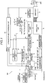
- the motor control device 100 is configured to control driving of a motor 200 provided with a permanent magnet (not illustrated) in response to a d-axis current command idref and a q-axis current command iqref that are set on the basis of a torque command Tref.
- a permanent magnet not illustrated
- the motor 200 is provided with a plurality of permanent magnets.
- the motor 200 is an interior permanent magnet (IPM) motor in which permanent magnets are buried in a rotor (not illustrated) or a surface permanent magnet (SPM) motor in which permanent magnets are disposed on a surface of a rotor.
- IPM interior permanent magnet
- SPM surface permanent magnet
- the motor control device 100 includes a torque/current conversion unit 1.
- the torque command Tref is input to the torque/current conversion unit 1 via a power management control unit 2.
- An angular velocity ⁇ s ⁇ of the motor 200 estimated by an electrical angle estimation unit 12 which will be described later is input to the torque/current conversion unit 1.
- the torque/current conversion unit 1 calculates a d-axis current command idrefidn and a q-axis current command iqrefidn on the basis of the torque command Tref and the angular velocity ⁇ s ⁇ of the motor 200.
- the motor control device 100 includes a current/voltage conversion unit 4.
- the current/voltage conversion unit 4 converts the d-axis current command idrefidn and the q-axis current command iqrefidn calculated by the torque/current conversion unit 1 into a d-axis voltage command vdref and a q-axis voltage command vqref, respectively.
- a d-axis current id and a q-axis current iq from a 3-phase/2-phase conversion unit 13 are input to the current/voltage conversion unit 4.
- the current/voltage conversion unit 4 integrates a difference between the d-axis current command idref and the d-axis current id and a difference between the q-axis current command iqref and the q-axis current iq.
- a difference integral value of the d-axis current command idref and the d-axis current id and a difference integral value of the q-axis current command iqref and the q-axis current iq are added in a state of being respectively multiplied by gains (ki and kp).
- the motor control device 100 includes a limiting unit 5.
- the limiting unit 5 is configured to limit increases of the d-axis voltage command vdref and the q-axis voltage command vqref output from the current/voltage conversion unit 4. For example, in a case where the d-axis voltage command vdref (q-axis voltage command vqref) is equal to or less than a predetermined threshold value, the d-axis voltage command vdref (q-axis voltage command vqref) is output to have an original value from the limiting unit 5.
- the d-axis voltage command vdref (q-axis voltage command vqref) is more than a limiter vdlim (vqlim)
- the d-axis voltage command vdref (q-axis voltage command vqref) is converted into a value (any constant value) of the limiter vdlim (vqlim) and is output.
- the motor control device 100 includes a 2-phase/3-phase conversion unit 6.
- the 2-phase/3-phase conversion unit 6 is configured to subject the d-axis voltage command vdref (q-axis voltage command vqref) output from the limiting unit 5 to inverse Park transform and inverse Clarke transform, and thus to output voltages vu, vv, and vw corresponding to 3-phase voltage values.
- the motor control device 100 includes a modulation unit 7.
- the modulation unit 7 performs envelope center shift modulation on the voltages vu, vv, and vw that are input from the 2-phase/3-phase conversion unit 6. Specifically, the modulation unit 7 compares values of the voltages vu, vv, and vw with each other, and uses 1/2 of an intermediate value of the voltages vu, vv, and vw as a correction value.
- the modulation unit 7 is configured to subtract the correction value from the voltages vu, vv, and vw and to output subtracted values.
- the motor control device 100 includes a PWM output unit 8.
- the PWM output unit 8 outputs PWM signals pwmu, pwmv, and pwmw for driving a plurality of bridge-connected switching elements (not illustrated) included in a drive unit 9 on the basis of signals (signals obtained by subtracting the correction value from the voltages vu, vv, and vw) output from the modulation unit 7.
- the motor control device 100 includes the drive unit 9.
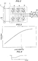
- the drive unit 9 applies the 3-phase voltages vu, vv, and vw to the motor 200 by turning on and off a plurality of switching elements 9a (refer to Fig. 2 ) on the basis of the PWM signals pwmu, pwmv, and pwmw. Consequently, the motor 200 is rotated at a speed corresponding to cycles of the applied voltages vu, vv, and vw.
- the motor control device 100 includes a current limiting unit 10.
- the current limiting unit 10 is configured to limit a current used to control (vector control) the motor 200.
- the current limiting unit 10 is configured to limit a current such that a current larger than current limitations (lam and lame) does not flow in vector control for the motor 200.
- the motor control device 100 includes a delay compensation unit 11.
- the delay compensation unit 11 is configured to compensate for a rotation delay of the motor 200. Generally, rotation of the motor 200 is delayed due to a plurality of factors such as delays of a calculation process of software or a response of the motor 200.
- the delay compensation unit 11 inputs a delay angle ( ⁇ c) to the 2-phase/3-phase conversion unit 6 on the basis of a delay time obtained by taking into consideration the plurality of factors and the angular velocity ⁇ s ⁇ estimated by the electrical angle estimation unit 12. A detailed configuration of the electrical angle estimation unit 12 will be described later.
- the delay compensation unit 11 is configured not to perform delay compensation on a 3-phase/2-phase conversion unit 13 which will be described later, and to perform delay compensation on the 2-phase/3-phase conversion unit 6. In other words, the delay compensation is performed on only the 2-phase/3-phase conversion unit 6, and is not performed on the 3-phase/2-phase conversion unit 13 to which a current including the influence of weak magnetic flux control is input.
- the motor control device 100 includes the 3-phase/2-phase conversion unit 13.
- the 3-phase/2-phase conversion unit 13 subjects excitation currents lu, Iv, and Iw with the respective phases of the motor 200 to Clarke transform and Park transform, and thus calculates the q-axis current iq and the d-axis current id.
- the excitation currents lu, Iv, and Iw with the respective phases of the motor 200 are detected separately for each phase.
- the excitation currents lu, Iv, and Iw with the respective phases are detected according to a three-shunt method.
- a shunt resistor 20 is provided for each phase on a downstream side of an H bridge circuit including the plurality of switching elements 9a.
- the excitation currents lu, Iv, and Iw are detected by the three shunt resistors 20.
- the motor control device 100 includes a noninterference control unit 14.
- the noninterference control unit 14 performs predetermined calculation (calculation regarding interference between iq and id) on the angular velocity ⁇ s ⁇ that is input from the electrical angle estimation unit 12 and the q-axis current iq and the d-axis current id that are output from the 3-phase/2-phase conversion unit 13, and outputs correction values vd1 and vq1 to the limiting unit 5.
- the motor control device 100 includes a determination unit 15 that determines (identifies) a d-axis inductance Ld, a q-axis inductance Lq, an armature resistance Ra, an armature interlinkage flux vector ⁇ a (torque constant Kt) that are parameters for controlling driving of the motor 200.
- the motor control device 100 includes a nonlinearization processing unit 16 that extends the armature interlinkage flux vector ⁇ a, the d-axis inductance Ld, and the q-axis inductance Lq determined by the determination unit 15 to a nonlinear region in which a magnetic flux change is nonlinear.
- the torque/current conversion unit 1 is configured to calculate the d-axis current command idrefidn and the q-axis current command iqrefidn on the basis of the armature interlinkage flux vector ⁇ a, the d-axis inductance Ld, and the q-axis inductance Lq extended to the nonlinear region by the nonlinearization processing unit 16. Details of extension to the nonlinear region will be described later.
- a linear region and the nonlinear region will be described.
- torque longitudinal axis
- q-axis current transverse axis
- the torque increases substantially linearly (substantially straight line shape) as the q-axis current increases.
- the torque increases nonlinearly as the q-axis current increases. Specifically, an increase amount of the torque is gradually reduced as the q-axis current increases.
- Fig. 3 illustrates a relationship between the q-axis current and the torque, and a relationship between a d-axis current and torque is the same as in Fig. 3 .
- the electrical angle estimation unit 12 is configured to estimate an electrical angle of the motor 200 according to at least one of a first method, a second method, and a third method on the basis of an angular velocity ⁇ of the motor 200, a modulation rate of a pwm signal, and whether a magnetic flux change is included in the linear region or the nonlinear region.
- the first method is a method of estimating an electrical angle ( ⁇ vd ⁇ ) of the motor 200 on the basis that a leakage current in the q axis becomes zero by applying a voltage to the d axis.
- the second method is a method of estimating an electrical angle ( ⁇ 0 ⁇ , ⁇ 0t ⁇ , ⁇ 0e ⁇ , and ⁇ 01e ⁇ ) of the motor 200 on the basis that at least one of a phase current difference and a line current difference caused by an induced voltage generated due to rotation of the motor 200 is zero.
- the third method is a method of estimating an electrical angle ( ⁇ o ⁇ ) on the basis of a voltage equation. An electrical angle ( ⁇ p ⁇ ) corresponding to an initial position is estimated in a region in which an angular velocity of the motor 200 is substantially 0.
- initial position estimation voltages are applied to the permanent magnets, and ripples of currents when the voltages are applied are integrated.
- An initial position ( ⁇ p ⁇ ) of an electrical angle is estimated on the basis of a polarity of the integral value ( ⁇ pd ⁇ and ⁇ pq ⁇ in the following table 2).
- Initial positions of a salient-pole machine and a non-salient-pole machine may be determined on the basis of ⁇ pd ⁇ and ⁇ pq ⁇ .
- the initial position estimation is performed only once when an angular velocity of the motor 200 is substantially 0.
- ⁇ p ⁇ is set as an initial value in the first method ( ⁇ vd ⁇ ) which will be described later.
- Table 2 Polarity of ⁇ pd ⁇ Polarity of ⁇ pq ⁇ ⁇ p ⁇ + + 0 to -90 deg + - 0 to 90 deg - + -90 to -180 deg - - 90 to 180 deg
- a voltage is applied to the d axis, and the voltage applied to the d axis is adjusted such that a leakage current that leaks in the q axis is 0. Consequently, the electrical angle ( ⁇ vd ⁇ ) can be indirectly estimated.
- the electrical angle estimation unit 12 is configured to reduce a sampling interval for estimating an electrical angle according to the first method in a case where a change rate ( ⁇ iqref) of the q-axis current is high more than in a case where the change rate of the q-axis current is low.
- the change rate ( ⁇ iqref) of the q-axis current increases at a low speed and a high load (when ⁇ i is large).
- a sampling interval ( ⁇ t) is reduced, and a width of the pwm signal is also reduced, according to the magnitude of the change rate ( ⁇ iqref) of the q-axis current. Consequently, it is possible to reduce an error in estimation of the electrical angle ( ⁇ vd ⁇ ). It is possible to reduce a switching loss.
- the electrical angle estimation unit 12 is configured to correct the electrical angle ( ⁇ vd ⁇ ) that is estimated when magnetic flux is saturated, on the basis of the following Equation 7.
- ⁇ vd ⁇ ⁇ vd ⁇ ⁇ SV 0 / SV 1
- SV 0 ⁇ ⁇ Kt ⁇ idn 0 + Ld ⁇ idn 0 ⁇ Lq ⁇ idn 0 ⁇ ⁇ ⁇ ⁇ idrefn ⁇ p iqrefn
- SV 1 ⁇ ⁇ ⁇ Kt ⁇ idn + Ld ⁇ idn ⁇ Lq ⁇ idn ⁇ ⁇ ⁇ ⁇ idrefn ⁇ piqrefn
- ⁇ indicates an angular velocity
- Kt indicates a counter-electromotive force constant
- Ld indicates d-axis inductance
- Lq indicates q-axis inductance
- idrefn indicates a d-axis current command value
- iqrefn indicates a q-axis current command value.
- the subscript ind indicates the present value
- the subscript indO indicates a value in a region in which magnetic flux of the motor is not saturated.
- p indicates time differentiation.
- the difference between the q-axis inductance Lq and the d-axis inductance Ld is increased according to at least one of an increase of the q-axis inductance Lq and a reduction of the d-axis inductance Ld.
- the first method is used in a case where an angular velocity of the motor 200 is low (in a case of a low velocity), but, in a case where a salient-pole difference (difference between Lq and Ld) is relatively small, it is difficult to estimate the electrical angle ⁇ vd ⁇ . Therefore, as described above, the difference Lq and Ld is increased.
- the weak magnetic flux reduces the torque of the motor 200 and also causes demagnetization.
- respective magnetic saturation points of the d axis and the q axis are close to each other.
- the motor 200 is brought into a strong magnetic flux state, and thus Ld is reduced in a magnetic saturation region. Consequently, a salient-pole difference (difference between Lq and Ld) is increased.
- ⁇ vd ⁇ the electrical angle ⁇ vd ⁇ .
- the motor 200 is brought into a strong magnetic flux state, and thus the torque of the motor 200 increases in a low speed region. In other words, there is an advantage in that the torque for activating the motor 200 increases. In intermediate speed and high speed regions, the process (reducing Ld) is not performed, and the process does not influence performance of the motor 200 in the intermediate speed and high speed regions.
- the inductance L of a coil is represented by the following Equation 8.
- L ⁇ ⁇ N 2 ⁇ S / I
- ⁇ indicates permeability
- N indicates the number of turns of the coil
- S indicates a sectional area
- I indicates a coil length
- step S1 the determination unit 15 determines (identifies parameters) Lq and Ld.
- step S2 it is determined whether or not a difference between Lq and Ld is more than 0 and is equal to or less than a predetermined threshold value (k ⁇ ).
- a predetermined threshold value k ⁇
- an linjdc flag is turned on. Consequently, as illustrated in Fig. 6 , a DC saturation voltage vdsat is applied in a direction of a strong magnetic flux with respect to the voltage ⁇ Vd (in the first method, a voltage applied to the d axis) such that the motor 200 is brought into a strong magnetic flux state.
- a saturation current (linjdc) in the d axis flows.
- step S4 it is determined whether or not the difference between Lq and Ld is more than the predetermined threshold value (k ⁇ ). In a case of yes in step S4, the flow proceeds to step S5, and the electrical angle ⁇ vd ⁇ is estimated.
- step S6 it is determined whether or not the difference between Lq and Ld is more than the predetermined threshold value (k ⁇ ). In a case of yes in step S6, the flow proceeds to step S5, and the electrical angle ⁇ vd ⁇ is estimated. In a case of no in step S6 (that is, in a case where the difference between Lq and Ld is less than 0), the flow proceeds to step S7. In other words, the electrical angle ⁇ vd ⁇ is not estimated (the electrical angle ⁇ vd ⁇ cannot be estimated).
- step S4 the flow proceeds to step S8, and the linjdc flag is turned off. Thereafter, the flow proceeds to step S7.
- the second method includes a method ( ⁇ 0 ⁇ ) based on a phase current difference, a method ( ⁇ 01 ⁇ ) based on a line current difference, a method ( ⁇ 0e ⁇ ) based on a current value in a stationary coordinate system, and a method ( ⁇ 01e ⁇ ) based on a current difference when two phases are short-circuited to each other.
- E indicates a phase induced voltage
- L indicates reluctance
- i indicates a current
- Ri indicates resistance
- the phase induced voltage E may be represented by a temporal change of a phase current in a zero vector period. Consequently, it is possible to estimate the electrical angle ⁇ 0 ⁇ .
- the electrical angle ⁇ 01 ⁇ is estimated on the basis of the following Equation 11.
- Ev ⁇ sin ⁇ ⁇ 2 ⁇ / 3 ⁇ Ewsin ⁇ + 2 ⁇ / 3 + L div / dt ⁇ diw / dt + R iv ⁇ iw 0
- Equation 12 Evw ⁇ sin ⁇ ⁇ ⁇ Ldivw / dt
- the line induced voltage Evw may be represented by a temporal change of a line current in a zero vector period. Consequently, it is possible to estimate the electrical angle ⁇ 01 ⁇ .
- the electrical angle ( ⁇ 0e ⁇ ) is estimated on the basis of the following Equation 13. ⁇ 0 e ⁇ ⁇ tan ⁇ 1 pi ⁇ / pi ⁇ ⁇ ⁇ / 2
- i ⁇ indicates a current of the ⁇ axis in the stationary coordinate system
- i ⁇ indicates a current of the ⁇ axis in the stationary coordinate system
- p indicates time differentiation.
- ⁇ 0e ⁇ is approximately obtained on the basis of a ratio between temporal change rates of a ⁇ -axis current and an ⁇ -axis current in the stationary coordinate system.
- the electrical angle ⁇ 0e ⁇ is a backup when the electrical angle ⁇ 0 ⁇ cannot be detected. Consequently, it is possible to improve stability of detection of a zero-cross. Either the detection of the electrical angle ⁇ 0e ⁇ or the detection of the electrical angle ⁇ 0 ⁇ may be performed.
- an electrical angle of the motor 200 is configured to be estimated on the basis of current values in two phases in which absolute values of current values or absolute values of change amounts of currents are greater among the three phases.
- pi ⁇ and pi ⁇ are obtained on the basis of the following Equation 14.
- pi ⁇ and pi ⁇ are obtained on the basis of the following Equation 15.
- pi ⁇ 1 / ⁇ 2 ⁇ piv ⁇ piw
- pi ⁇ ⁇ 3 / 2 ⁇ ⁇ piv ⁇ piw
- pi ⁇ and pi ⁇ are obtained on the basis of the following Equation 16.
- iq and id respectively indicate a q-axis current and a d-axis current.
- iu, iv, and iw respectively indicate a u-phase current, a v-phase current, and a w-phase current.
- R indicates resistance.
- the electrical angle ⁇ 01e ⁇ is a backup when the electrical angle ⁇ 01 ⁇ cannot be detected. Consequently, it is possible to improve stability of detection of a zero-cross. Either the detection of the electrical angle ⁇ 01e ⁇ or the detection of the electrical angle ⁇ 01 ⁇ may be performed.
- an electrical angle can be estimated by using only ⁇ (estimated value) and equipment constants as shown in the following Equation 20.
- the electrical angle estimation unit 12 is configured to estimate an electrical angle at which a phase current difference is zero and an electrical angle at which a line current difference is zero on the basis of the following Equations 21 and 22 when the phase current difference is not zero and when the line current difference is not zero.
- ⁇ 0t ⁇ and ⁇ 01t ⁇ respectively indicate target values (an electrical angle of every 60 degrees from 0 degrees, and an electrical angle of every 60 degrees from 30 degrees), ⁇ i* indicates a current difference, and ⁇ 1* indicates a change rate of ⁇ i*.
- * indicates the d axis or the q axis.
- the electrical angle ( ⁇ o ⁇ ) is estimated on the basis of the following Equation 23.
- the third method is referred to as an adaptive observer model.
- ⁇ o ⁇ tan ⁇ 1 ⁇ / ⁇
- ⁇ indicates a field magnetic flux linkage of an armature coil
- subscripts ⁇ and ⁇ indicate the stationary coordinate system (the ⁇ axis and the ⁇ axis).
- the electrical angle estimation unit 12 estimates an electrical angle according to the first method ( ⁇ vd ⁇ ) and the second method ( ⁇ 0 ⁇ , ⁇ 0t ⁇ , ⁇ 0e ⁇ , and ⁇ 01e ⁇ ) in a case where an angular velocity of the motor 200 is low (low velocity). In a very low region of the low speed, ⁇ 0e ⁇ is not estimated. In a case where an angular velocity of the motor 200 is high (an intermediate velocity or a high velocity), an electrical angle is configured to be estimated according to the second method ( ⁇ 0 ⁇ , ⁇ 0t ⁇ , and ⁇ 0e ⁇ ) and the third method ( ⁇ o ⁇ ).
- the electrical angle estimation unit 12 is configured to estimate an electrical angle according to the second method ( ⁇ 0 ⁇ and ⁇ 0e ⁇ ).
- estimation of the electrical angle ⁇ 0 ⁇ is performed every 60 degrees from 0 degrees. Specifically, in a case where the motor 200 is rotated clockwise, the electrical angle ⁇ 0 ⁇ is estimated at 0 degrees, 60 degrees, 120 degrees, 180 degrees, 240 degrees, and 300 degrees. In a case where the motor 200 is rotated counterclockwise, the electrical angle ⁇ 0 ⁇ is estimated at 0 degrees, -60 degrees, -120 degrees, -180 degrees, -240 degrees, and -300 degrees.
- Estimation of the electrical angle ⁇ 01 ⁇ is performed every 60 degrees from 30 degrees. Specifically, in a case where the motor 200 is rotated clockwise, the electrical angle ⁇ 01 ⁇ is estimated at 30 degrees, 90 degrees, 150 degrees, 210 degrees, 270 degrees, and 330 degrees. In a case where the motor 200 is rotated counterclockwise, the electrical angle ⁇ 01 ⁇ is estimated at -30 degrees, -90 degrees, -150 degrees, -210 degrees, -270 degrees, and -330 degrees.
- the electrical angle estimation unit 12 is configured to estimate a plurality of predetermined electrical angles (only ⁇ 0e ⁇ or both of ⁇ 0 ⁇ and ⁇ 0e ⁇ ) and also to estimate an electrical angle between the predetermined electrical angles through interpolation calculation.
- An electrical angle ⁇ 0 ⁇ t between predetermined electrical angles is estimated through interpolation calculation on the basis of the following Equation 24.
- ⁇ 0* ⁇ t1 indicates a certain electrical angle (for example, 0 degrees)
- t1 indicates a time of entering a certain zone (for example, between 0 degrees to 60 degrees)
- d ⁇ indicates acceleration of an electrical angle
- ⁇ 0 ⁇ indicates an estimated value of an angular velocity of the motor 200
- kj indicates a map (refer to Fig. 7 ) of d ⁇ .
- the electrical angle ⁇ 0 ⁇ t is estimated through interpolation calculation as illustrated in Fig. 8 on the basis of the above equation.
- a zero vector (active zero vector) is forced to be applied. Specifically, the active zero vector is applied around the electrical angle ⁇ 0 ⁇ of every 60 degrees from 0 degrees. Consequently, the electrical angle ⁇ 0e ⁇ is estimated.
- the responsiveness of a servomotor it is necessary to perform estimation of an electrical angle from a relatively low velocity (the intermediate velocity in Table 1) to a region in which an induced voltage is generated, the electrical angle ⁇ o ⁇ is estimated in addition to the electrical angles ( ⁇ 0 ⁇ , ⁇ 0t ⁇ , ⁇ 0e ⁇ , and ⁇ 01e ⁇ ) based on a zero-cross.
- the responsiveness of a servomotor is not required, only the electrical angles ( ⁇ 0 ⁇ , ⁇ 0t ⁇ , ⁇ 0e ⁇ , and ⁇ 01e ⁇ ) based on a zero-cross are estimated. Consequently, it is possible to reduce a load on the motor control device 100.
- the electrical angle estimation unit 12 is configured to replace (subjected to an override) the electrical angle estimated according to at least one of the first method and the third method with the electrical angle estimated according to the second method.
- the electrical angle ⁇ vd ⁇ estimated according to the first method in a predetermined electrical angle (an electrical angle of every 60 degrees from 0 degrees, or an electrical angle of every 60 degrees from 30 degrees), the electrical angle ⁇ vd ⁇ estimated according to the first method is replaced (subjected to an override) with an electrical angle (any one of ⁇ 0 ⁇ , ⁇ 0t ⁇ , ⁇ 0e ⁇ , and ⁇ 01e ⁇ ) estimated according to the second method.
- the electrical angle ⁇ vd ⁇ estimated according to the first method or the electrical angle ⁇ o ⁇ estimated according to the third method in a predetermined electrical angle, the electrical angle ⁇ vd ⁇ estimated according to the first method or the electrical angle ⁇ o ⁇ estimated according to the third method is replaced with an electrical angle (any one of ⁇ 0 ⁇ , ⁇ 0t ⁇ , and ⁇ 0e ⁇ ) estimated according to the second method.
- the electrical angle ⁇ o ⁇ is estimated according to the third method
- the electrical angle ⁇ 0 ⁇ estimated according to the third method is replaced with an electrical angle (any one of ⁇ 0 ⁇ , ⁇ 0t ⁇ , and ⁇ 0e ⁇ ) estimated according to the second method.
- the override is performed at a timing at which a phase current difference or a line current difference is zero. Specifically, a timing at which a phase current difference is zero (zero-cross) is every 60 degrees from 0 degrees. A timing at which a line current difference is zero is every 60 degrees from 30 degrees.
- the zero vector active zero vector
- an electrical angle ( ⁇ 0 ⁇ , ⁇ 0t ⁇ , ⁇ 0e ⁇ , and ⁇ 01e ⁇ ) is detected according to the second method.
- the zero vector active zero vector
- the zero vector is forced to be applied around an electrical angle of every 60 degrees from 0 degrees. Consequently, an electrical angle ( ⁇ 0 ⁇ and ⁇ 0e ⁇ ) is detected according to the second method.
- An electrical angle estimated value includes an estimated value for electrical angle estimation and an electrical angle estimated value for control (speed control and position control).
- the estimated value for electrical angle estimation is an estimated value (an immediate value ( ⁇ s ⁇ ; refer to a thick solid line in Fig. 10 ) that is estimated according to the first to third methods.
- the electrical angle estimated value for control is subjected to smoothing (refer to a thick dotted line in Fig. 10 ). Specifically, smoothing is performed on a value of the latest electrical angle before the override to be proportional to the angular velocity ⁇ . An electrical angle for angular velocity estimation is not subjected to smoothing. Consequently, it is possible to improve controllability while maintaining the accuracy of estimation of an electrical angle (angular velocity).
- the override is performed by using the electrical angle ⁇ 0e ⁇ in a region in which an angular velocity is relatively high. This is because, in a case where a modulation rate becomes high, deviation from sinusoidal driving increases, and thus an error increases in the method of estimating the electrical angle ⁇ 0 ⁇ . In the region in which an angular velocity is relatively high, it is possible to estimate an electrical angle with high accuracy on the basis of only the electrical angle ⁇ 0e ⁇ (refer to the following Equation 25).
- An angular velocity of a motor to which the method ( ⁇ 0e ⁇ ) based on a current value in the stationary coordinate system is applied is higher than an angular velocity of a motor to which the method ( ⁇ 01e ⁇ ) based on a current difference when two phases are short-circuited to each other is applied.
- k ⁇ 01e and k ⁇ 0e are coefficients having characteristics illustrated in Fig. 11 .
- k ⁇ 01e is 1 in a region in which the angular velocity
- k ⁇ 01e decreases linearly from 1 to 0 in a region in which the angular velocity
- k ⁇ 0e is 0 in a region in which the angular velocity
- k ⁇ 0e increases linearly from 0 to 1 in a region in which the angular velocity
- the electrical angle estimation unit 12 is configured to estimate an electrical angle by performing sampling for detecting an electrical angle a plurality of times, and performing movement averaging on results of the plurality of times of sampling. For example, as illustrated in Fig. 12 , in estimation of the electrical angle ⁇ 0 ⁇ and the electrical angle ⁇ 0t ⁇ , a plurality of times of sampling is performed (for example, ten times every 5 degrees) in an electrical angle around a zero-cross. A zero-cross is detected on the basis of a change in a sign of a differential movement average of a plurality of times of sampling.
- a plurality of times of sampling is performed, and the electrical angle ⁇ 0e ⁇ and the electrical angle ⁇ 01e ⁇ are estimated on the basis of a movement average of sampling results.
- the number of times of sampling is increased as the angular velocity ⁇ of the motor 200 becomes lower.
- the number of times of sampling is exponentially increased as the angular velocity ⁇ of the motor 200 becomes lower.
- the override is performed on a first half and a second half of a pwm signal.
- the override may be performed for each cycle (every cycle or every two cycles) of the pwm signal. This is because, in the second method (electrical angle estimation using a current ripple), in a case where an equipment constant La/Ra (electrical time constant) of the motor 200 is large, a zero-cross may not be detected.
- the electrical angle estimation unit 12 is configured to compensate for a delay of an electrical angle estimated according to the second method on the basis of the equipment constant of the motor 200. Specifically, in a case where the angular velocity
- the electrical angle estimation unit 12 calculates the angular velocity ⁇ by performing time differentiation on an estimated electrical angle. For example, an angular velocity ⁇ vd ⁇ is calculated on the basis of the electrical angle ⁇ vd ⁇ estimated according to the first method. An angular velocity ⁇ 0 ⁇ is calculated on the basis of the electrical angles ⁇ 0 ⁇ , ⁇ 0t ⁇ , ⁇ 0e ⁇ , and ⁇ 01e ⁇ estimated according to the second method. An angular velocity ⁇ o ⁇ is calculated on the basis of the electrical angle ⁇ o ⁇ estimated according to the third method.
- the angular velocity ⁇ o ⁇ estimated according to the third method is replaced (subjected to an override) with the angular velocity ⁇ 0 ⁇ estimated according to the second method.
- the angular velocity ⁇ is calculated on the basis of time differentiation of the latest estimated electrical angle.
- an angular velocity estimated value for control is subjected to smoothing.
- An angular velocity for angular velocity estimation is not subjected to smoothing.
- the electrical angle estimation unit 12 estimates an initial position ( ⁇ p ⁇ ) of the motor 200 on the basis that voltages are applied to the permanent magnets of the motor 200 in a case where the angular velocity ⁇ of the motor 200 is around zero. In a case where the angular velocity ⁇ of the motor 200 is more than around zero, the electrical angle estimation unit 12 continuously estimates an electrical angle according to the first method ( ⁇ vd ⁇ ) and the second method (only ⁇ 0 ⁇ or both of ⁇ 0 ⁇ and ⁇ 0e ⁇ ). In a case where step-out of the motor 200 is detected a predetermined number of times or more within a predetermined period, the electrical angle estimation unit 12 is configured to stop the motor 200.
- step-out resultantly occurs.
- the step-out since the override is performed at the zero-cross timing, the step-out does not occur logically. However, the step-out may occur at the time of a rapid change of the angular velocity ⁇ . Therefore, the above-described measure is performed.
- the electrical angle estimation unit 12 is configured to replace the electrical angle ( ⁇ vd ⁇ and ⁇ o ⁇ ) estimated according to at least one of the first method and the third method with the electrical angle ( ⁇ 0 ⁇ , ⁇ 0t ⁇ , ⁇ 0e ⁇ , and ⁇ 01e ⁇ ) estimated according to the second method.
- an electrical angle ( ⁇ 0 ⁇ , ⁇ 0t ⁇ , ⁇ 0e ⁇ , and ⁇ 01e ⁇ ) can be relatively accurately estimated by detecting a timing (zero-cross timing) at which a phase current difference or a line current difference is zero. Consequently, in a case where an electrical angle ( ⁇ vd ⁇ and ⁇ o ⁇ ) is successively estimated according to at least one of the first method and the third method, even though an error occurs in the estimated electrical angle ( ⁇ vd ⁇ and ⁇ o ⁇ ), the error can be corrected by using the electrical angle ( ⁇ 0 ⁇ , ⁇ 0t ⁇ , ⁇ 0e ⁇ , and ⁇ 01e ⁇ ) estimated according to the second method at the zero-cross timing. As a result, in a case where an electrical angle is successively estimated, it is possible to correct an error in an estimated electrical angle.
- the first method in which the accuracy of estimation of the electrical angle ⁇ vd ⁇ is relatively high is used in a case where the angular velocity ⁇ of the motor 200 is low
- the third method in which the accuracy of estimation of the electrical angle ⁇ o ⁇ is relatively high is used in a case where the angular velocity ⁇ of the motor 200 is high
- an electrical angle can be estimated at only a zero-cross timing (30 degrees, 60 degrees, 90 degrees, and the like), and thus electrical angles at timings other than the zero-cross timing can be estimated by performing interpolation calculation.
- an electrical angle may be estimated on the basis of Equations 21 and 22.
- an electrical angle ( ⁇ 0 ⁇ , ⁇ 0t ⁇ , ⁇ 0e ⁇ , and ⁇ 01e ⁇ ) is estimated on the basis of a current (a phase current and a line current), and thus a phase may be delayed with respect to a voltage. Therefore, a delay of the electrical angle ( ⁇ 0 ⁇ , ⁇ 0t ⁇ , ⁇ 0e ⁇ , and ⁇ 01e ⁇ ) (phase) is compensated for, and thus it is possible to improve the accuracy of estimation of the electrical angle ( ⁇ 0 ⁇ , ⁇ 0t ⁇ , ⁇ 0e ⁇ , and ⁇ 01e ⁇ ).
- an electrical angle can be estimated according to the method ( ⁇ 0e ⁇ ) based on a current value in the stationary coordinate system and the method ( ⁇ 01e ⁇ ) based on a current difference when two phases are short-circuited to each other.
- an electrical angle of the motor 200 is estimated on the basis of current values in two phases in which absolute values of the current values or absolute values of change amounts of currents are greater, and thus it is possible to improve noise resistance with respect to a current value and a change amount of the current value.
- noise is reduced on the basis of a d-axis current value and a q-axis current value, and thus it is possible to increase the accuracy of estimation of an electrical angle ( ⁇ 0e ⁇ ).
- a method ( ⁇ 0e ⁇ and ⁇ 01e ⁇ ) for increasing the accuracy of estimation of an electrical angle is selected depending on an angular velocity of the motor 200, and thus it is possible to further increase the accuracy of estimation of an electrical angle.
- an electrical angle ( ⁇ vd ⁇ ) can be appropriately estimated according to the first method.
- an electrical angle ( ⁇ vd ⁇ ) can be appropriately estimated.
- the motor 200 in a case where the angular velocity ⁇ of the motor 200 is around zero, an initial position of the motor 200 is estimated, and thus it is possible to estimate the subsequent electrical angle with high accuracy. In a case where step-out of the motor 200 is detected a predetermined number of times or more within a predetermined period, the motor 200 is stopped, and thus it is possible to prevent driving of the motor 200 from being continued in a state in which the motor 200 steps out.
- the angular velocity ⁇ 0 ⁇ is substituted on the basis of the electrical angles ⁇ 0 ⁇ , ⁇ 0t ⁇ , ⁇ 0e ⁇ , and ⁇ 01e ⁇ estimated according to the second method in which an electrical angle can be relatively accurately estimated, and thus it is possible to improve the accuracy of estimation of an electrical angle and also to improve the robustness of the estimation of an electrical angle.
- the first embodiment even in a case where it is difficult to estimate the electrical angle ⁇ vd ⁇ according to the first embodiment due to a relatively small difference between the q-axis inductance Lq and the d-axis inductance Ld, it is possible to easily estimate the electrical angle ⁇ vd ⁇ by increasing a difference between the q-axis inductance Lq and the d-axis inductance Ld.
- a current is detected (single-shunt method) by a single shunt resistor 20 unlike in the first embodiment in which a current is detected by the three shunt resistors 20.
- the shunt resistor 20 (current detection portion) is provided in a drive unit 109 of the motor control device 100.
- the shunt resistor 20 is configured to detect a current flowing through a DC side (positive side: P) of 3-phase AC for supplying power from a power supply unit 210 to the motor 200.
- the shunt resistor 20 may be configured to detect a current flowing through a GND side. Phase currents on the downstream side of the switching elements 9a are indicated by iuL, ivL, and iwL.
- Fig. 15 illustrates an example of one cycle of a PWM signal pwm*.
- a length of one cycle is referred to as a period T
- a start point of the cycle is referred to as a start point t0
- a period in which a voltage is applied from the power supply unit 210 to only the U phase is referred to as T100.
- Applying a voltage from the power supply unit 210 will be referred to as "voltage application”, and not applying a voltage will be referred to as "voltage nonapplication”.
- a period of U phase voltage application, V phase voltage application, and W phase voltage nonapplication is referred to as T110
- a period of U phase voltage application, V phase voltage application, and W phase voltage application is referred to as T111
- a period of U phase voltage nonapplication, V phase voltage nonapplication, and W phase voltage nonapplication is referred to as T000.
- a "zero vector" is assumed to indicate a state in the period T000.
- a detected current ir, the phase currents iu, iv, and iw, and the phase currents iuL, ivL, and iwL have a relationship represented by the following Equation 27.
- the currents have a relationship represented by the following Equation 28 in the period T110.
- a current iut0 (iu at the start point t0), ivt0 (iv at the start point t0), and iwt0 (iw at the start point t0) have a relationship represented by the following Equation 29.
- the electrical angle estimation unit 12 does not use the method (electrical angle ⁇ 0 ⁇ ) based on a phase current difference and the method (electrical angle ⁇ 0e ⁇ ) based on a current value in the stationary coordinate system in the second method. This is because, in the single-shunt method, a circulating current in a zero vector state (a state in which all the switching elements 9a of an upper arm or a lower arm are turned off) cannot be detected.
- the electrical angle estimation unit 12 is configured to estimate an electrical angle according to at least one of the method (electrical angle ⁇ 01 ⁇ ) based on a line current difference and the method (electrical angle ⁇ 01e ⁇ ) based on a current difference when two phases are short-circuited to each other (in the second embodiment, both of the methods).
- step S11 it is determined whether or not the motor 200 is in a zero-cross state (a phase current difference is 0).
- a zero-cross timing is 30 degrees, 90 degrees, 150 degrees, 210 degrees, 270 degrees, and 330 degrees. Actually, the zero-cross timing (electrical angle) is within a range of the angles ⁇ k0 deg.
- step S12 it is determined whether or not a cycle of pwm is an even number.
- step S13 an electrical angle is estimated according to at least one of the method (electrical angle ⁇ 01 ⁇ ) based on a line current difference and the method (electrical angle ⁇ 01e ⁇ ) based on a current difference when two phases are short-circuited to each other.
- an electrical angle estimation pulse shift process is performed.
- the electrical angle estimation pulse shift process is a process for securing the minimum time for detecting a state in which two phases are short-circuited to each other even in a case where the state in which two phases are short-circuited to each other cannot be detected through a single-shunt pulse shift process which will be described later. Specifically, as illustrated in Fig.
- a pulse width of a pwm signal is increased and decreased in order to secure the minimum time for detecting a state in which two phases are short-circuited to each other. For example, at a timing at which a current is detected, a pulse width of a pwm signal (pwmv) is increased (refer to a dotted line in Fig. 17 ). A pulse width of the pwm signal is decreased at another timing in order to complement the increase of the pulse width of the pwm signal. Consequently, the output amount of whole current is not changed. A current value detected through the electrical angle estimation pulse shift process is used for current control.
- step S14 the single-shunt pulse shift process is performed.
- the single-shunt pulse shift process is a process of moving (shifting) a pulse width of a pwm signal with respect to a triangular wave C such that a pulse of the pwm signal is generated at the time at which a detection current is detected.
- the electrical angle estimation pulse shift process is different from the single-shunt pulse shift process in terms of processing method. Therefore, as described above, the electrical angle estimation pulse shift process and the single-shunt pulse shift process are switched to each other depending on whether a cycle of pwm is an even number or an odd number, and thus it is possible to suppress interference in both of the processes.
- Remaining configurations of the second embodiment are the same as those of the first embodiment.
- an electrical angle ⁇ ev ⁇ is estimated on the basis of an induced voltage in an off vector state unlike in the second embodiment in which an electrical angle is estimated on the basis of the electrical angle ⁇ 01 ⁇ and the electrical angle ⁇ 01e ⁇ .
- the second method further includes a method of estimating an electrical angle on the basis of an induced voltage in a zero vector state in a case where a current supplied to the motor 200 is detected by a single shunt resistor 20.
- the electrical angle ⁇ ev ⁇ is estimated on the basis of a line induced voltage as shown in the following Equation 30.
- V ⁇ 2 / 3 ⁇ Euv ⁇ Evw / 2 ⁇ Ewu / 2
- Euv indicates a line induced voltage between the U phase and the V phase
- Evw indicates a line induced voltage between the V phase and the W phase
- Ewu indicates a line induced voltage between the W phase and the U phase.
- Equation 31 the line induced voltages are represented by the following Equation 31.
- ke indicates a counter-electromotive force constant
- kvgain indicates a voltage read gain
- Eu, Ev, and Ew respectively indicate terminal induced voltages with the U phase, the V phase, and the W phase.
- ⁇ indicates an electrical angular velocity.
- the electrical angle ⁇ ev ⁇ may be estimated on the basis of a phase voltage (a terminal induced voltage between a neutral point and a terminal with each phase) as shown in the following Equation 32.
- V ⁇ 2 / 3 ⁇ Eu ⁇ ⁇ Ev ⁇ / 2 ⁇ Ew ⁇ / 2
- the electrical angle ⁇ ev ⁇ estimated on the basis of a phase voltage switches between angles depending on whether the motor 200 is rotated clockwise (cw) or counterclockwise (ccw).
- Equation 33 The terminal induced voltages are represented by the following Equation 33.
- Eu, Ev, and Ew respectively indicate terminal induced voltages with the U phase, the V phase, and the W phase.
- the neutral point is required to be detected by hardware or to be estimated by software.
- a current value read according to the electrical angle estimation pulse shift process of the second embodiment is not used for current control. This is because the read current value is a current value in a zero vector state (off vector state).
- a timing at which an off vector is applied is 0 degrees, 60 degrees, 120 degrees, 180 degrees, 240 degrees, and 300 degrees. Actually, the timing at which an off vector is applied is within a range of the angles ⁇ k0 deg. In this case, since a difference between the terminal induced voltages is not taken, the off vector is applied once.
- Remaining configurations of the third embodiment are the same as those of the first and second embodiments.
- an electrical angle is estimated on the basis of the above Equations 21 and 22 when a phase current difference is not zero and when a line current difference is not zero, but the present invention is not limited thereto. In the present invention, an electrical angle may not be estimated on the basis of the above Equations 21 and 22.
- the electrical angle estimation pulse shift process and the single-shunt pulse shift process are alternately performed with respect to a cycle (an even number and an odd number) of pwm, but the present invention is not limited thereto.
- the electrical angle estimation pulse shift process may be performed once with respect to a plurality of single-shunt pulse shift processes.
Landscapes
- Engineering & Computer Science (AREA)
- Power Engineering (AREA)
- Control Of Ac Motors In General (AREA)
- Control Of Motors That Do Not Use Commutators (AREA)
Abstract
Description
- This disclosure relates to a motor control device, and particularly to a motor control device including an electrical angle estimation unit that estimates an electrical angle of a motor.
- In the related art, there is a motor control device including an electrical angle estimation unit estimating an electrical angle of a motor (for example, refer to
Japanese Patent No. 3312472 JP 2017-70122A - In
Reference 1, an alternating voltage is applied to a motor, and a motor current that flows due to the application of the alternating voltage (AC voltage) is detected. The detected motor current is divided into a component parallel to and a component orthogonal to the applied alternating voltage. Here, in a case where the alternating voltage is applied to the motor, a current also flows in a direction orthogonal to a vector of the alternating voltage except when the vector of the alternating voltage is parallel or orthogonal to a rotor magnetic pole axis. The current is detected, and thus a phase difference angle between the vector of the alternating voltage and a magnetic flux axis can be detected. A phase of the vector of the alternating voltage that is applied such that a phase difference angle becomes zero is adjusted, and thus a magnetic pole position (electrical angle) is indirectly estimated. - In
Reference 2, an electrical angle of a motor is estimated on the basis of an adaptive observer model and an extended induced voltage observer model. In the adaptive observer model, a state (magnetic flux) and an output (current) of an AC motor are estimated through calculation on the basis of an input (a voltage command for an inverter) for the AC motor, and an electrical angle is estimated on the basis of a deviation between an estimated current and a current detected by a current sensor. In the extended induced voltage observer model, an electrical angle is estimated by using a state quantity such as an extended induced voltage having position information of a rotor on the basis of motor parameters such as a resistance and an inductance that are measurable in advance and physical quantities such as a current and a voltage that are detectable by sensors. - In the estimation of an electrical angle disclosed in
Reference 1 andReference 2, the electrical angle may be successively estimated (at a relatively small angle interval). - Here, in the estimation of an electrical angle disclosed in
Reference 1 andReference 2, the electrical angle may be successively estimated (at a relatively small angle interval), and a problem that there is a case where an error occurs in the estimation of the electrical angle has been found. - Thus, a need exists for a motor control device capable of correcting an error in an estimated electrical angle in a case where the electrical angle is successively estimated.
- A motor control device according to an aspect of the present invention controls driving of a motor provided with a permanent magnet in response to a d-axis current command and a q-axis current command that are set on the basis of a torque command, and the motor control device includes an electrical angle estimation unit configured to estimate an electrical angle of the motor according to at least one of a first method of estimating the electrical angle of the motor on the basis that a leakage current in a q axis becomes zero by applying a voltage to a d axis and, a second method of estimating the electrical angle of the motor on the basis of at least one of a phase current difference and a line current difference caused by an induced voltage generated due to rotation of the motor becomes zero, and a third method of estimating the electrical angle on the basis of a voltage equation, depending on an angular velocity of the motor, a modulation rate of a pwm signal, and whether a magnetic flux change is included in a nonlinear region in which the magnetic flux change is nonlinear, in which, in a case where the electrical angle of the motor is estimated according to at least one of the first method and the third method, with respect to the electrical angle estimated according to the second method, the electrical angle estimation unit is configured to replace the electrical angle estimated according to at least one of the first method and the third method with the electrical angle estimated according to the second method.
- In the motor control device according to the aspect of the present invention, as described above, in a case where the electrical angle of the motor is estimated according to at least one of the first method and the third method, with respect to the electrical angle estimated according to the second method, the electrical angle estimation unit is configured to replace the electrical angle estimated according to at least one of the first method and the third method with the electrical angle estimated according to the second method. Here, in the second method, an electrical angle can be relatively accurately estimated by detecting a timing (zero-cross timing) at which at least one of the phase current difference and the line current difference is zero. Consequently, in a case where an electrical angle is successively estimated according to at least one of the first method and the third method, even though an error occurs in the estimated electrical angle, the error can be corrected by using the electrical angle estimated according to the second method at the zero-cross timing. As a result, in a case where an electrical angle is successively estimated, it is possible to correct an error in an estimated electrical angle.
- In the motor control device according to the aspect, it is preferable that the electrical angle estimation unit is configured to estimate the electrical angle according to the first method and the second method in a case where the angular velocity of the motor is low, and estimate the electrical angle according to the second method and the third method in a case where the angular velocity of the motor is high.
- With this configuration, since the first method in which the accuracy of estimation of an electrical angle is relatively high is used in a case where an angular velocity of the motor is low, and the third method in which the accuracy of estimation of an electrical angle is relatively high is used in a case where the angular velocity of the motor is relatively high, it is possible to perform estimation of an electrical angle with high accuracy in both of the cases where the angular velocity of the motor is low and high. As a result, it is possible to correct an error in an estimated electrical angle while performing estimation of an electrical angle with high accuracy in both of the cases where the angular velocity of the motor is low and high.
- In the motor control device according to the aspect, it is preferable that, in a case of overmodulation in which the modulation rate of the pwm signal is 1 or greater and in the nonlinear region in which the magnetic flux change is nonlinear, the electrical angle estimation unit is configured to estimate the electrical angle according to the second method.
- Here, in the first method and the third method, in a case of overmodulation of a pwm signal and in a nonlinear region, estimation of an electrical angle cannot be performed with high accuracy. Therefore, with this configuration, a zero-cross timing is detected according to the second method, and thus an electrical angle can be relatively accurately estimated even in the case of overmodulation of a pwm signal and in the nonlinear region.
- In this case, it is preferable that, in the second method in the nonlinear region in which the magnetic flux change is nonlinear, the electrical angle estimation unit is configured to estimate a plurality of predetermined electrical angles, and estimate an electrical angle between the predetermined electrical angles through interpolation calculation.
- with this configuration, as described above, in the second method, an electrical angle can be estimated at only a zero-cross timing (30 degrees, 60 degrees, 90 degrees, and the like), and thus electrical angles at timings other than the zero-cross timing can be estimated by performing interpolation calculation.
- In the motor control device according to the aspect, it is preferable that, in the second method, when the phase current difference is not zero and when the line current difference is not zero, the electrical angle estimation unit is configured to estimate an electrical angle at which the phase current difference is zero and an electrical angle at which the line current difference is zero on the basis of the following Equations 4 and 5:


- With this configuration, when a zero-cross timing cannot be detected according to the second method, an electrical angle can be estimated on the basis of
Equations 4 and 5. - In the motor control device according to the aspect, it is preferable that, in the second method, the electrical angle estimation unit is configured to compensate for a delay of the electrical angle estimated according to the second method on the basis of an equipment constant of the motor.
- In this configuration, in the second method, an electrical angle is estimated on the basis of a current (a phase current and a line current), and thus a phase may be delayed with respect to a voltage. Therefore, with this configuration, a delay of the electrical angle (phase) is compensated for, and thus it is possible to improve the accuracy of estimation of the electrical angle.
- In the motor control device according to the aspect, it is preferable that the second method includes a method based on a current value in a stationary coordinate system and a method based on a current difference when two phases are short-circuited to each other, in addition to a method based on the phase current difference and a method based on the line current difference.
- With this configuration, even in a case where an electrical angle cannot be appropriately estimated according to the method based on a phase current difference and the method based on a line current difference, an electrical angle can be estimated according to the method based on a current value in the stationary coordinate system and the method based on a current difference when two phases are short-circuited to each other.
- In this case, in the motor control device according to the aspect, it is preferable that, in the method based on the current value in the stationary coordinate system, the electrical angle estimation unit is configured to estimate the electrical angle of the motor on the basis of current values in two phases in which absolute values of current values or absolute values of change amounts of currents are greater among three phases.
- With this configuration, it is possible to improve noise resistance with respect to a current value and a change amount of the current value.
- In the motor control device in which the second method includes the method based on the current value in the stationary coordinate system and the method based on the current difference when the two phases are short-circuited to each other, in the method based on the current value in the stationary coordinate system, it is preferable that the electrical angle estimation unit is configured to reduce noise on the basis of a d-axis current value and a q-axis current value.
- With this configuration, noise is reduced, and thus it is possible to increase the accuracy of estimation of an electrical angle.
- In the motor control device in which the second method includes the method based on the current value in the stationary coordinate system and the method based on the current difference when the two phases are short-circuited to each other, it is preferable that an angular velocity of the motor to which the method based on the current value in the stationary coordinate system is applied is higher than an angular velocity of the motor to which the method based on the current difference when the two phases are short-circuited to each other is applied.
- With this configuration, a method for increasing the accuracy of estimation of an electrical angle is selected depending on an angular velocity of the motor, and thus it is possible to further increase the accuracy of estimation of an electrical angle.
- In the motor control device in which the second method includes the method based on the current value in the stationary coordinate system and the method based on the current difference when the two phases are short-circuited to each other, it is preferable that, in a case where a current supplied to the motor is detected by a single shunt resistor, in the second method, the electrical angle estimation unit is configured to estimates the electrical angle according to the at least one of the method based on the line current difference and the method based on the current difference when the two phases are short-circuited to each other, instead of using the method based on the phase current difference and the method based on the current value in the stationary coordinate system.
- With this configuration, according to at least one of the method based on the line current difference and the method based on the current difference when the two phases are short-circuited to each other, it is possible to estimate an electrical angle even in a case where a current supplied to the motor is detected by the single shunt resistor (in a case where a current value is detected at a separate time point for each phase). Consequently, it is possible to appropriately estimate an electrical angle even in a case where a current supplied to the motor is detected by the single shunt resistor.
- In the motor control device in which the second method includes the method based on the current value in the stationary coordinate system and the method based on the current difference when the two phases are short-circuited to each other, it is preferable that, in a case where a current supplied to the motor is detected by a single shunt resistor, the second method further includes a method of estimating the electrical angle on the basis of an induced voltage in an off vector state. Here, the "off vector state" indicates that all switching elements are turned off in an H bridge circuit (power conversion circuit) including a plurality of switching elements (an upper arm and a lower arm).
- With this configuration, in the method of estimating an electrical angle on the basis of an induced voltage in an off vector state, robustness is relatively higher than in the method based on the line current difference and the method based on the current difference when the two phases are short-circuited to each other, and thus it is possible to more appropriately estimate an electrical angle.
- In the motor control device according to the aspect, it is preferable that, in the second method, the electrical angle estimation unit is configured to estimates an electrical angle by performing a plurality of times of sampling for detecting an electrical angle such that the number of times of sampling is increased as the angular velocity of the motor becomes lower, and performing movement averaging on results of the plurality of times of sampling.
- With this configuration, even in a case where noise is included in a current (a phase current or a line current), it is possible to reduce the influence of the noise.
- In the motor control device according to the aspect, it is preferable that, in the first method, the electrical angle estimation unit is configured to reduces an interval of sampling for estimating the electrical angle according to the first method in a case where a change rate of a q-axis current is high more than in a case where the change rate of the q-axis current is low.
- With this configuration, even in a case where a change rate of a q-axis current is high, an electrical angle can be appropriately estimated according to the first method.
- In the motor control device according to the aspect, it is preferable that, in the first method, the electrical angle estimation unit is configured to corrects an electrical angle estimated when magnetic flux is saturated on the basis of the following Equation 6:

- With this configuration, even in a case where magnetic flux is saturated, an electrical angle can be appropriately estimated.
- In the motor control device according to the aspect, it is preferable that, the electrical angle estimation unit is configured to performs a smoothing process such that values before and after replacement are continued when an estimated value that is estimated according to at least one of the first method and the third method is replaced with the electrical angle estimated according to the second method.
- With this configuration, it is possible to suppress an estimated electrical angle from rapidly changing.
- In the motor control device according to the aspect, it is preferable that, when the motor steps out, the electrical angle estimation unit is configured to estimate an initial position of the motor on the basis of a voltage being applied to the permanent magnet of the motor in a case where the angular velocity of the motor is around zero, continuously estimate the electrical angle in a case where the angular velocity of the motor is more than around zero, and stop the motor in a case where step-out of the motor is detected a predetermined number of times or more within a predetermined period.
- With this configuration, in a case where an angular velocity of the motor is around zero, an initial position of the motor is estimated, and thus it is possible to estimate the subsequent electrical angle with high accuracy. In a case where step-out of the motor is detected a predetermined number of times or more within a predetermined period, the motor is stopped, and thus it is possible to prevent driving of the motor from being continued in a state in which the motor steps out.
- In the motor control device according to the aspect, it is preferable that the electrical angle estimation unit is configured to perform time differentiation on the estimated electrical angle so as to calculate the angular velocity, and replace an angular velocity calculated on the basis of the electrical angle estimated according to the third method with an angular velocity calculated on the basis of the electrical angle estimated according to the second method.
- With this configuration, an angular velocity is substituted on the basis of electrical angles estimated according to the second method in which an electrical angle can be relatively accurately estimated, and thus it is possible to improve the accuracy of estimation of an electrical angle and also to improve the robustness of the estimation of an electrical angle.
- In the motor control device according to the aspect, it is preferable that, in the first method, in a case where a difference between q-axis inductance and d-axis inductance is less than a predetermined threshold value, the difference between the q-axis inductance and the d-axis inductance is increased by performing at least one of an increase of the q-axis inductance and a decrease of the d-axis inductance.
- With this configuration, even in a case where it is difficult to estimate an electrical angle according to the first method due to a relatively small difference between the q-axis inductance and the d-axis inductance, it is possible to easily estimate an electrical angle by using the configuration.
- The foregoing and additional features and characteristics of this disclosure will become more apparent from the following detailed description considered with the reference to the accompanying drawings, wherein:
-
Fig. 1 is a block diagram illustrating a motor control device according to a first embodiment disclosed here; -
Fig. 2 is a diagram for describing current detection according to a three-shunt method; -
Fig. 3 is a diagram illustrating a relationship between a q-axis current and torque; -
Fig. 4 is a diagram illustrating a relationship between a change rate of the q-axis current and a load; -
Fig. 5 is a flowchart for describing a process of estimating an electrical angle according to a first method; -
Fig. 6 is a block diagram (partially enlarged view) illustrating the motor control device according to the first embodiment disclosed here; -
Fig. 7 is a diagram illustrating a map of dω; -
Fig. 8 is a diagram for describing interpolation calculation; -
Fig. 9 is a diagram for describing switching between the first method and a third method; -
Fig. 10 is a diagram for describing smoothing of an estimated electrical angle; -
Fig. 11 is a diagram for describing switching (combined calculation) between θ0e^ and θ01e^; -
Fig. 12 is a diagram for describing a plurality of times of sampling; -
Fig. 13 is a diagram for describing correction of a phase of an electrical angle estimated according to a second method; -
Fig. 14 is a diagram for describing current detection according to a single-shunt method according to a second embodiment disclosed here; -
Fig. 15 is a diagram for describing a PWM signal; -
Fig. 16 is a flowchart for describing a process of estimating an electrical angle according to a second method according to the second embodiment disclosed here; -
Fig. 17 is a diagram for describing an electrical angle estimation pulse shift process; and -
Fig. 18 is a diagram for describing a single-shunt pulse shift process. - Hereinafter, embodiments disclosed here will be described with reference to the drawings.
- With reference to
Figs. 1 to 13 , a description will be made of a configuration of amotor control device 100 according to a first embodiment. In the following description, "ref" indicates a command, and "idn" indicates a time lapse and extension to a nonlinear region. - As illustrated in
Fig. 1 , themotor control device 100 is configured to control driving of amotor 200 provided with a permanent magnet (not illustrated) in response to a d-axis current command idref and a q-axis current command iqref that are set on the basis of a torque command Tref. Hereinafter, details thereof will be described. - The
motor 200 is provided with a plurality of permanent magnets. Themotor 200 is an interior permanent magnet (IPM) motor in which permanent magnets are buried in a rotor (not illustrated) or a surface permanent magnet (SPM) motor in which permanent magnets are disposed on a surface of a rotor. - The
motor control device 100 includes a torque/current conversion unit 1. The torque command Tref is input to the torque/current conversion unit 1 via a powermanagement control unit 2. An angular velocity ωs^ of themotor 200 estimated by an electricalangle estimation unit 12 which will be described later is input to the torque/current conversion unit 1. The torque/current conversion unit 1 calculates a d-axis current command idrefidn and a q-axis current command iqrefidn on the basis of the torque command Tref and the angular velocity ωs^ of themotor 200. - The
motor control device 100 includes a current/voltage conversion unit 4. The current/voltage conversion unit 4 converts the d-axis current command idrefidn and the q-axis current command iqrefidn calculated by the torque/current conversion unit 1 into a d-axis voltage command vdref and a q-axis voltage command vqref, respectively. - Specifically, a d-axis current id and a q-axis current iq from a 3-phase/2-
phase conversion unit 13 are input to the current/voltage conversion unit 4. The current/voltage conversion unit 4 integrates a difference between the d-axis current command idref and the d-axis current id and a difference between the q-axis current command iqref and the q-axis current iq. A difference integral value of the d-axis current command idref and the d-axis current id and a difference integral value of the q-axis current command iqref and the q-axis current iq are added in a state of being respectively multiplied by gains (ki and kp). - The
motor control device 100 includes a limitingunit 5. The limitingunit 5 is configured to limit increases of the d-axis voltage command vdref and the q-axis voltage command vqref output from the current/voltage conversion unit 4. For example, in a case where the d-axis voltage command vdref (q-axis voltage command vqref) is equal to or less than a predetermined threshold value, the d-axis voltage command vdref (q-axis voltage command vqref) is output to have an original value from the limitingunit 5. On the other hand, in a case where the d-axis voltage command vdref (q-axis voltage command vqref) is more than a limiter vdlim (vqlim), the d-axis voltage command vdref (q-axis voltage command vqref) is converted into a value (any constant value) of the limiter vdlim (vqlim) and is output. - The
motor control device 100 includes a 2-phase/3-phase conversion unit 6. The 2-phase/3-phase conversion unit 6 is configured to subject the d-axis voltage command vdref (q-axis voltage command vqref) output from the limitingunit 5 to inverse Park transform and inverse Clarke transform, and thus to output voltages vu, vv, and vw corresponding to 3-phase voltage values. - The
motor control device 100 includes amodulation unit 7. Themodulation unit 7 performs envelope center shift modulation on the voltages vu, vv, and vw that are input from the 2-phase/3-phase conversion unit 6. Specifically, themodulation unit 7 compares values of the voltages vu, vv, and vw with each other, and uses 1/2 of an intermediate value of the voltages vu, vv, and vw as a correction value. Themodulation unit 7 is configured to subtract the correction value from the voltages vu, vv, and vw and to output subtracted values. - The
motor control device 100 includes aPWM output unit 8. ThePWM output unit 8 outputs PWM signals pwmu, pwmv, and pwmw for driving a plurality of bridge-connected switching elements (not illustrated) included in adrive unit 9 on the basis of signals (signals obtained by subtracting the correction value from the voltages vu, vv, and vw) output from themodulation unit 7. - The
motor control device 100 includes thedrive unit 9. Thedrive unit 9 applies the 3-phase voltages vu, vv, and vw to themotor 200 by turning on and off a plurality of switchingelements 9a (refer toFig. 2 ) on the basis of the PWM signals pwmu, pwmv, and pwmw. Consequently, themotor 200 is rotated at a speed corresponding to cycles of the applied voltages vu, vv, and vw. - The
motor control device 100 includes a current limitingunit 10. The current limitingunit 10 is configured to limit a current used to control (vector control) themotor 200. In other words, the current limitingunit 10 is configured to limit a current such that a current larger than current limitations (lam and lame) does not flow in vector control for themotor 200. - The
motor control device 100 includes adelay compensation unit 11. Thedelay compensation unit 11 is configured to compensate for a rotation delay of themotor 200. Generally, rotation of themotor 200 is delayed due to a plurality of factors such as delays of a calculation process of software or a response of themotor 200. Thedelay compensation unit 11 inputs a delay angle (θc) to the 2-phase/3-phase conversion unit 6 on the basis of a delay time obtained by taking into consideration the plurality of factors and the angular velocity ωs^ estimated by the electricalangle estimation unit 12. A detailed configuration of the electricalangle estimation unit 12 will be described later. - The
delay compensation unit 11 is configured not to perform delay compensation on a 3-phase/2-phase conversion unit 13 which will be described later, and to perform delay compensation on the 2-phase/3-phase conversion unit 6. In other words, the delay compensation is performed on only the 2-phase/3-phase conversion unit 6, and is not performed on the 3-phase/2-phase conversion unit 13 to which a current including the influence of weak magnetic flux control is input. - The
motor control device 100 includes the 3-phase/2-phase conversion unit 13. The 3-phase/2-phase conversion unit 13 subjects excitation currents lu, Iv, and Iw with the respective phases of themotor 200 to Clarke transform and Park transform, and thus calculates the q-axis current iq and the d-axis current id. - As illustrated in
Fig. 2 , the excitation currents lu, Iv, and Iw with the respective phases of themotor 200 are detected separately for each phase. In other words, the excitation currents lu, Iv, and Iw with the respective phases are detected according to a three-shunt method. Specifically, ashunt resistor 20 is provided for each phase on a downstream side of an H bridge circuit including the plurality of switchingelements 9a. The excitation currents lu, Iv, and Iw are detected by the threeshunt resistors 20. - The
motor control device 100 includes anoninterference control unit 14. Thenoninterference control unit 14 performs predetermined calculation (calculation regarding interference between iq and id) on the angular velocity ωs^ that is input from the electricalangle estimation unit 12 and the q-axis current iq and the d-axis current id that are output from the 3-phase/2-phase conversion unit 13, and outputs correction values vd1 and vq1 to the limitingunit 5. - The
motor control device 100 includes adetermination unit 15 that determines (identifies) a d-axis inductance Ld, a q-axis inductance Lq, an armature resistance Ra, an armature interlinkage flux vector φa (torque constant Kt) that are parameters for controlling driving of themotor 200. - The
motor control device 100 includes anonlinearization processing unit 16 that extends the armature interlinkage flux vector φa, the d-axis inductance Ld, and the q-axis inductance Lq determined by thedetermination unit 15 to a nonlinear region in which a magnetic flux change is nonlinear. The torque/current conversion unit 1 is configured to calculate the d-axis current command idrefidn and the q-axis current command iqrefidn on the basis of the armature interlinkage flux vector φa, the d-axis inductance Ld, and the q-axis inductance Lq extended to the nonlinear region by thenonlinearization processing unit 16. Details of extension to the nonlinear region will be described later. - With reference to
Fig. 3 , a linear region and the nonlinear region will be described. As illustrated inFig. 3 , torque (longitudinal axis) increases as a q-axis current (transverse axis) increases. Here, in a case where the q-axis current is smaller than iqsat, the torque increases substantially linearly (substantially straight line shape) as the q-axis current increases. On the other hand, in a case where the q-axis current is equal to or larger than iqsat, the torque increases nonlinearly as the q-axis current increases. Specifically, an increase amount of the torque is gradually reduced as the q-axis current increases. In other words, as the q-axis current increases, the magnetic flux change increases linearly and then increases nonlinearly. In the present specification, the region where the q-axis current is smaller than iqsat will be referred to as a linear region, and the region where the q-axis current is equal to or larger than iqsat will be referred to as a nonlinear region.Fig. 3 illustrates a relationship between the q-axis current and the torque, and a relationship between a d-axis current and torque is the same as inFig. 3 . - Next, a description will be made of a detailed configuration of the electrical
angle estimation unit 12. - Here, in the first embodiment, as shown in the following Table 1, the electrical
angle estimation unit 12 is configured to estimate an electrical angle of themotor 200 according to at least one of a first method, a second method, and a third method on the basis of an angular velocity ω^ of themotor 200, a modulation rate of a pwm signal, and whether a magnetic flux change is included in the linear region or the nonlinear region. The first method is a method of estimating an electrical angle (θvd^) of themotor 200 on the basis that a leakage current in the q axis becomes zero by applying a voltage to the d axis. The second method is a method of estimating an electrical angle (θ0^, θ0t^, θ0e^, and θ01e^) of themotor 200 on the basis that at least one of a phase current difference and a line current difference caused by an induced voltage generated due to rotation of themotor 200 is zero. The third method is a method of estimating an electrical angle (θo^) on the basis of a voltage equation. An electrical angle (Δθp^) corresponding to an initial position is estimated in a region in which an angular velocity of themotor 200 is substantially 0. Hereinafter, details thereof will be described.Table 1 Angular velocity (ω^) Around zero Low velocity Intermediate velocity High velocity Overmodulation Nonlinear region Step-out (low velocity) Step-out (high velocity) θ0^ O O (O) (O) O θ0e^ O O O O (O) θ01^ O O O θ01e^ O Δθp^ O O θvd^ O O O O θo^ O O - In initial position estimation, voltages are applied to the permanent magnets, and ripples of currents when the voltages are applied are integrated. An initial position (Δθp^) of an electrical angle is estimated on the basis of a polarity of the integral value (∑θpd^ and ∑θpq^ in the following table 2). Initial positions of a salient-pole machine and a non-salient-pole machine may be determined on the basis of ∑θpd^ and ∑θpq^. The initial position estimation is performed only once when an angular velocity of the
motor 200 is substantially 0. In addition, Δθp^ is set as an initial value in the first method (θvd^) which will be described later.Table 2 Polarity of Σθpd^ Polarity of ∑θpq^ Δθp^ + + 0 to -90 deg + - 0 to 90 deg - + -90 to -180 deg - - 90 to 180 deg - In the first method, a voltage is applied to the d axis, and the voltage applied to the d axis is adjusted such that a leakage current that leaks in the q axis is 0. Consequently, the electrical angle (θvd^) can be indirectly estimated.
- In the first method, the electrical
angle estimation unit 12 is configured to reduce a sampling interval for estimating an electrical angle according to the first method in a case where a change rate (Δiqref) of the q-axis current is high more than in a case where the change rate of the q-axis current is low. Specifically, as illustrated inFig. 4 , the change rate (Δiqref) of the q-axis current increases at a low speed and a high load (when ωi is large). In this case, a sampling interval (Δt) is reduced, and a width of the pwm signal is also reduced, according to the magnitude of the change rate (Δiqref) of the q-axis current. Consequently, it is possible to reduce an error in estimation of the electrical angle (θvd^). It is possible to reduce a switching loss. - In the first method, the electrical
angle estimation unit 12 is configured to correct the electrical angle (θvd^) that is estimated when magnetic flux is saturated, on the basis of the followingEquation 7.
- Here, ω indicates an angular velocity, Kt indicates a counter-electromotive force constant, Ld indicates d-axis inductance, Lq indicates q-axis inductance, idrefn indicates a d-axis current command value, and iqrefn indicates a q-axis current command value. The subscript ind indicates the present value, and the subscript indO indicates a value in a region in which magnetic flux of the motor is not saturated. In addition, p indicates time differentiation.
- Here, in a case where a load of the
motor 200 increases, and thus a current amount increases, a phenomenon in which magnetic flux is saturated occurs. Consequently, the saliency of local inductance decreases nonlinearly, and thus the sensitivity of magnetic pole position detection using the saliency in a high load region deteriorates. Therefore, as described above, the electrical angle (θvd^) estimated when magnetic flux is saturated is corrected. - Here, in the first embodiment, in the first method, in a case where a difference between the q-axis inductance Lq and the d-axis inductance Ld is less than a predetermined threshold value, the difference between the q-axis inductance Lq and the d-axis inductance Ld is increased according to at least one of an increase of the q-axis inductance Lq and a reduction of the d-axis inductance Ld. Here, the first method is used in a case where an angular velocity of the
motor 200 is low (in a case of a low velocity), but, in a case where a salient-pole difference (difference between Lq and Ld) is relatively small, it is difficult to estimate the electrical angle θvd^. Therefore, as described above, the difference Lq and Ld is increased. - There are many control restrictions such as a torque reduction or interferences, and thus the d axis is adjusted. The weak magnetic flux reduces the torque of the
motor 200 and also causes demagnetization. In themotor 200 with relatively small saliency, respective magnetic saturation points of the d axis and the q axis are close to each other. Themotor 200 is brought into a strong magnetic flux state, and thus Ld is reduced in a magnetic saturation region. Consequently, a salient-pole difference (difference between Lq and Ld) is increased. As a result, it is possible to easily estimate the electrical angle θvd^. Themotor 200 is brought into a strong magnetic flux state, and thus the torque of themotor 200 increases in a low speed region. In other words, there is an advantage in that the torque for activating themotor 200 increases. In intermediate speed and high speed regions, the process (reducing Ld) is not performed, and the process does not influence performance of themotor 200 in the intermediate speed and high speed regions. - The inductance L of a coil is represented by the following
Equation 8.
- Here, µ indicates permeability, N indicates the number of turns of the coil, S indicates a sectional area, and I indicates a coil length. Magnetic saturation occurs in the strong magnetic flux state (a state in which a current increases in a magnetic flux direction of a magnet). Consequently, the permeability µ is reduced. As a result, L is reduced. Assuming that Ld is reduced, and Lq does not change, a salient-pole difference (actually, an inverse salient-pole difference) increases. The
motor 200 has an inverse salient-pole difference in which Lq is larger than Ld (Lq > Ld). - Specifically, as illustrated in
Fig. 5 , the following process is performed. First, in step S1, thedetermination unit 15 determines (identifies parameters) Lq and Ld. - Next, in step S2, it is determined whether or not a difference between Lq and Ld is more than 0 and is equal to or less than a predetermined threshold value (kΔθ). In a case of yes in step S2, in step S3, an linjdc flag is turned on. Consequently, as illustrated in
Fig. 6 , a DC saturation voltage vdsat is applied in a direction of a strong magnetic flux with respect to the voltage ΔVd (in the first method, a voltage applied to the d axis) such that themotor 200 is brought into a strong magnetic flux state. As a result, a saturation current (linjdc) in the d axis flows. - Next, in step S4, it is determined whether or not the difference between Lq and Ld is more than the predetermined threshold value (kΔθ). In a case of yes in step S4, the flow proceeds to step S5, and the electrical angle θvd^ is estimated.
- In a case of no in step S2, the flow proceeds to step S6. In step S6, it is determined whether or not the difference between Lq and Ld is more than the predetermined threshold value (kΔθ). In a case of yes in step S6, the flow proceeds to step S5, and the electrical angle θvd^ is estimated. In a case of no in step S6 (that is, in a case where the difference between Lq and Ld is less than 0), the flow proceeds to step S7. In other words, the electrical angle θvd^ is not estimated (the electrical angle θvd^ cannot be estimated).
- In a case of no in step S4, the flow proceeds to step S8, and the linjdc flag is turned off. Thereafter, the flow proceeds to step S7.
- The second method includes a method (θ0^) based on a phase current difference, a method (θ01^) based on a line current difference, a method (θ0e^) based on a current value in a stationary coordinate system, and a method (θ01e^) based on a current difference when two phases are short-circuited to each other.
- In the method based on a phase current difference, the electrical angle θ0^ is estimated on the basis of the following
Equation 9.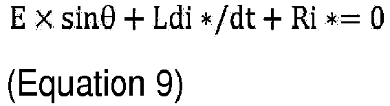
- Here, E indicates a phase induced voltage, L indicates reluctance, i indicates a current, Ri indicates resistance, and * indicates the d axis or the q axis. Since Ri = 0 around a zero-cross (a phase current difference is 0), the following
Equation 10 may be obtained.
- According to the above equation, the phase induced voltage E may be represented by a temporal change of a phase current in a zero vector period. Consequently, it is possible to estimate the electrical angle θ0^.
- In the method based on a line current difference, the electrical angle θ01^ is estimated on the basis of the following
Equation 11.
- Here, Ev and Ew indicates line induced voltages, L indicates reluctance, iv and iw indicate currents, and R indicates resistance. Since R = 0 around a zero-cross (a line current difference is 0), the following
Equation 12 may be obtained.
- According to the above equation, the line induced voltage Evw may be represented by a temporal change of a line current in a zero vector period. Consequently, it is possible to estimate the electrical angle θ01^.
- In the method based on current value in the stationary coordinate system, the electrical angle (θ0e^) is estimated on the basis of the following
Equation 13.
- Here, iα indicates a current of the α axis in the stationary coordinate system, and iβ indicates a current of the β axis in the stationary coordinate system. In addition, p indicates time differentiation. In other words, θ0e^ is approximately obtained on the basis of a ratio between temporal change rates of a β-axis current and an α-axis current in the stationary coordinate system. The electrical angle θ0e^ is a backup when the electrical angle θ0^ cannot be detected. Consequently, it is possible to improve stability of detection of a zero-cross. Either the detection of the electrical angle θ0e^ or the detection of the electrical angle θ0^ may be performed.
- Here, in the first embodiment, in the method based on a current value in the stationary coordinate system, an electrical angle of the
motor 200 is configured to be estimated on the basis of current values in two phases in which absolute values of current values or absolute values of change amounts of currents are greater among the three phases. Specifically, for example, in a case where absolute values of current values in the U phase and the V phase or absolute values of change amounts of currents thereof are greater (than that in the W phase), piα and piβ are obtained on the basis of the followingEquation 14.
- In a case where absolute values of current values in the V phase and the W phase or absolute values of change amounts of currents thereof are greater (than that in the U phase), piα and piβ are obtained on the basis of the following
Equation 15.
- In a case where absolute values of current values in the W phase and the U phase or absolute values of change amounts of currents thereof are greater (than that in the V phase), piα and piβ are obtained on the basis of the following
Equation 16.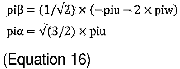
- The electrical
angle estimation unit 12 is configured to reduce noise on the basis of a d-axis current value and a q-axis current value in the method based on a current value in the stationary coordinate system. Specifically, noise is reduced on the basis of the following Equation 17.
- Here, iq and id respectively indicate a q-axis current and a d-axis current.
- In the method based on a current difference when two phases are short-circuited to each other, the electrical angle (θ01e^) is estimated on the basis of the following Equation 18.

- Here, iu, iv, and iw respectively indicate a u-phase current, a v-phase current, and a w-phase current. In addition, R indicates resistance. The electrical angle θ01e^ is a backup when the electrical angle θ01^ cannot be detected. Consequently, it is possible to improve stability of detection of a zero-cross. Either the detection of the electrical angle θ01e^ or the detection of the electrical angle θ01^ may be performed.
- The above Equation 18 may be represented by the following Equation 19 according to a boundary condition when two phases are short-circuited to each other.

- In a case where a current change rate is low (that is, in a case where p(iu) is about 0), an electrical angle can be estimated by using only ω (estimated value) and equipment constants as shown in the following
Equation 20.
- In the first embodiment, in the second method, the electrical
angle estimation unit 12 is configured to estimate an electrical angle at which a phase current difference is zero and an electrical angle at which a line current difference is zero on the basis of the following Equations 21 and 22 when the phase current difference is not zero and when the line current difference is not zero.

- Here, θ0t^ and θ01t^ respectively indicate target values (an electrical angle of every 60 degrees from 0 degrees, and an electrical angle of every 60 degrees from 30 degrees), Δi* indicates a current difference, and ΔΔ1* indicates a change rate of Δi*. In addition, * indicates the d axis or the q axis.
- In the third method, the electrical angle (θo^) is estimated on the basis of the following Equation 23. The third method is referred to as an adaptive observer model.

- Here, λ indicates a field magnetic flux linkage of an armature coil, and the subscripts α and β indicate the stationary coordinate system (the α axis and the β axis).
- Here, in the first embodiment, as shown in the above Table 1, the electrical
angle estimation unit 12 estimates an electrical angle according to the first method (θvd^) and the second method (θ0^, θ0t^, θ0e^, and θ01e^) in a case where an angular velocity of themotor 200 is low (low velocity). In a very low region of the low speed, θ0e^ is not estimated. In a case where an angular velocity of themotor 200 is high (an intermediate velocity or a high velocity), an electrical angle is configured to be estimated according to the second method (θ0^, θ0t^, and θ0e^) and the third method (θo^). In a case where an angular velocity of themotor 200 is intermediate, switching (combined calculation) between the first method (θvd^) and the third method (θo^) is performed. In a case of overmodulation in which a modulation rate of a pwm signal is 1 or greater, and in a nonlinear region in which a magnetic flux change is nonlinear, the electricalangle estimation unit 12 is configured to estimate an electrical angle according to the second method (θ0^ and θ0e^). - Specifically, estimation of the electrical angle θ0^ is performed every 60 degrees from 0 degrees. Specifically, in a case where the
motor 200 is rotated clockwise, the electrical angle θ0^ is estimated at 0 degrees, 60 degrees, 120 degrees, 180 degrees, 240 degrees, and 300 degrees. In a case where themotor 200 is rotated counterclockwise, the electrical angle θ0^ is estimated at 0 degrees, -60 degrees, -120 degrees, -180 degrees, -240 degrees, and -300 degrees. - Estimation of the electrical angle θ01^ is performed every 60 degrees from 30 degrees. Specifically, in a case where the
motor 200 is rotated clockwise, the electrical angle θ01^ is estimated at 30 degrees, 90 degrees, 150 degrees, 210 degrees, 270 degrees, and 330 degrees. In a case where themotor 200 is rotated counterclockwise, the electrical angle θ01^ is estimated at -30 degrees, -90 degrees, -150 degrees, -210 degrees, -270 degrees, and -330 degrees. - In the first embodiment, in the second method in a nonlinear region in which a magnetic flux change is nonlinear, the electrical
angle estimation unit 12 is configured to estimate a plurality of predetermined electrical angles (only θ0e^ or both of θ0^ and θ0e^) and also to estimate an electrical angle between the predetermined electrical angles through interpolation calculation. An electrical angle θ0^t between predetermined electrical angles (electrical angles every 60 degrees) is estimated through interpolation calculation on the basis of the following Equation 24.
- Here, θ0*^t1 indicates a certain electrical angle (for example, 0 degrees), t1 indicates a time of entering a certain zone (for example, between 0 degrees to 60 degrees), dω indicates acceleration of an electrical angle, ω0^ indicates an estimated value of an angular velocity of the
motor 200, and kj indicates a map (refer toFig. 7 ) of dω. The electrical angle θ0^t is estimated through interpolation calculation as illustrated inFig. 8 on the basis of the above equation. - In a case of overmodulation or in a nonlinear region, in a case where a voltage command in each phase is relatively large, and there is no timing at which a zero-cross is detectable (in a case where a zero-cross of a current change rate cannot be detected), a zero vector (active zero vector) is forced to be applied. Specifically, the active zero vector is applied around the electrical angle θ0^ of every 60 degrees from 0 degrees. Consequently, the electrical angle θ0e^ is estimated.
- In a case where the responsiveness of a servomotor is required, it is necessary to perform estimation of an electrical angle from a relatively low velocity (the intermediate velocity in Table 1) to a region in which an induced voltage is generated, the electrical angle θo^ is estimated in addition to the electrical angles (θ0^, θ0t^, θ0e^, and θ01e^) based on a zero-cross. On the other hand, in a case where the responsiveness of a servomotor is not required, only the electrical angles (θ0^, θ0t^, θ0e^, and θ01e^) based on a zero-cross are estimated. Consequently, it is possible to reduce a load on the
motor control device 100. - Here, in the first embodiment, in a case where an electrical angle of the motor is estimated according to at least one of the first method and the third method, with respect to an electrical angle estimated according to the second method, the electrical
angle estimation unit 12 is configured to replace (subjected to an override) the electrical angle estimated according to at least one of the first method and the third method with the electrical angle estimated according to the second method. Specifically, as shown in Table 1, in a region in which an angular velocity is low, when the electrical angle θvd^ is estimated according to the first method, in a predetermined electrical angle (an electrical angle of every 60 degrees from 0 degrees, or an electrical angle of every 60 degrees from 30 degrees), the electrical angle θvd^ estimated according to the first method is replaced (subjected to an override) with an electrical angle (any one of θ0^, θ0t^, θ0e^, and θ01e^) estimated according to the second method. In a region in which an angular velocity is intermediate, when the electrical angle θvd^ is estimated according to the first method or the electrical angle θo^ is estimated according to the third method, in a predetermined electrical angle, the electrical angle θvd^ estimated according to the first method or the electrical angle θo^ estimated according to the third method is replaced with an electrical angle (any one of θ0^, θ0t^, and θ0e^) estimated according to the second method. In a region in which an angular velocity is high, when the electrical angle θo^ is estimated according to the third method, in a predetermined electrical angle, the electrical angle θ0^ estimated according to the third method is replaced with an electrical angle (any one of θ0^, θ0t^, and θ0e^) estimated according to the second method. - As illustrated in
Fig. 9 , in the region in which an angular velocity is intermediate, switching between estimation of the electrical angle θvd^ according to the first method and the electrical angle θo^ according to the third method occurs. In a case where an angular velocity (|ω^|) is relatively low, the electrical angle θvd^ is estimated according to the first method, and, in a case where an angular velocity is relatively high, the electrical angle θo^ is estimated according to the third method. In a case where an angular velocity is substantially intermediate, combined calculation of the first method and the third method is performed. - The override is performed at a timing at which a phase current difference or a line current difference is zero. Specifically, a timing at which a phase current difference is zero (zero-cross) is every 60 degrees from 0 degrees. A timing at which a line current difference is zero is every 60 degrees from 30 degrees.
- In a case where the zero-cross cannot be detected for a while, for example, the zero vector (active zero vector) is forced to be applied around an electrical angle of every 60 degrees from 0 degrees. Consequently, an electrical angle (θ0^, θ0t^, θ0e^, and θ01e^) is detected according to the second method.
- In a case of overmodulation and in a nonlinear region, for example, the zero vector (active zero vector) is forced to be applied around an electrical angle of every 60 degrees from 0 degrees. Consequently, an electrical angle (θ0^ and θ0e^) is detected according to the second method.
- An electrical angle estimated value includes an estimated value for electrical angle estimation and an electrical angle estimated value for control (speed control and position control). The estimated value for electrical angle estimation is an estimated value (an immediate value (ωs^; refer to a thick solid line in
Fig. 10 ) that is estimated according to the first to third methods. On the other hand, as illustrated inFig. 10 , since there is a case where an estimated electrical angle has a discrete value (a value rapidly changes) due to an override, the electrical angle estimated value for control is subjected to smoothing (refer to a thick dotted line inFig. 10 ). Specifically, smoothing is performed on a value of the latest electrical angle before the override to be proportional to the angular velocity ω. An electrical angle for angular velocity estimation is not subjected to smoothing. Consequently, it is possible to improve controllability while maintaining the accuracy of estimation of an electrical angle (angular velocity). - As shown in Table 1, the override is performed by using the electrical angle θ0e^ in a region in which an angular velocity is relatively high. This is because, in a case where a modulation rate becomes high, deviation from sinusoidal driving increases, and thus an error increases in the method of estimating the electrical angle θ0^. In the region in which an angular velocity is relatively high, it is possible to estimate an electrical angle with high accuracy on the basis of only the electrical angle θ0e^ (refer to the following Equation 25).

- In addition, "(O)" in Table 1 indicates that estimation based on the electrical angle θ0^ is possible, and the estimation based on the electrical angle θ0^ is not performed for the above reason. Consequently, it is possible to reduce a load on the
motor control device 100 and also to improve the responsiveness of estimation of an electrical angle. Since there is no boundary condition in the electrical angle θ0e^ represented by theabove Equation 13, a zero-cross cannot be detected in a region in which an angular velocity is relatively high, but an electrical angle can be detected by using the electrical angle θ0e^ represented by theabove Equation 13. - An angular velocity of a motor to which the method (θ0e^) based on a current value in the stationary coordinate system is applied is higher than an angular velocity of a motor to which the method (θ01e^) based on a current difference when two phases are short-circuited to each other is applied. Specifically, the electrical angle θe^ is estimated on the basis of the following Equation 26.

- Here, kθ01e and kθ0e are coefficients having characteristics illustrated in
Fig. 11 . kθ01e is 1 in a region in which the angular velocity |ω^| is relatively low, and is 0 in a region in which the angular velocity|ω^| is relatively high. kθ01e decreases linearly from 1 to 0 in a region in which the angular velocity |ω^| is substantially intermediate. kθ0e is 0 in a region in which the angular velocity |ω^| is relatively low, and is 1 in a region in which the angular velocity |ω^| is relatively high. kθ0e increases linearly from 0 to 1 in a region in which the angular velocity |ω^| is substantially intermediate. Consequently, it is possible to improve the accuracy of estimation of an electrical angle. - In the second method, the electrical
angle estimation unit 12 is configured to estimate an electrical angle by performing sampling for detecting an electrical angle a plurality of times, and performing movement averaging on results of the plurality of times of sampling. For example, as illustrated inFig. 12 , in estimation of the electrical angle θ0^ and the electrical angle θ0t^, a plurality of times of sampling is performed (for example, ten times every 5 degrees) in an electrical angle around a zero-cross. A zero-cross is detected on the basis of a change in a sign of a differential movement average of a plurality of times of sampling. Similarly, for estimation of the electrical angle θ0e^ and the electrical angle θ01e^, a plurality of times of sampling is performed, and the electrical angle θ0e^ and the electrical angle θ01e^ are estimated on the basis of a movement average of sampling results. The number of times of sampling is increased as the angular velocity ω^ of themotor 200 becomes lower. For example, the number of times of sampling is exponentially increased as the angular velocity ω^ of themotor 200 becomes lower. - The override is performed on a first half and a second half of a pwm signal. On the other hand, the override may be performed for each cycle (every cycle or every two cycles) of the pwm signal. This is because, in the second method (electrical angle estimation using a current ripple), in a case where an equipment constant La/Ra (electrical time constant) of the
motor 200 is large, a zero-cross may not be detected. - In the first embodiment, in the second method, the electrical
angle estimation unit 12 is configured to compensate for a delay of an electrical angle estimated according to the second method on the basis of the equipment constant of themotor 200. Specifically, in a case where the angular velocity |ω^| is relatively high, the influence of the equipment constant La/Ra (electrical time constant) of themotor 200 cannot be disregarded, and thus a phase of an electrical angle estimated according to the second method is corrected. Specifically, as illustrated inFig. 13 , the correction is performed by subtracting an electrical angle (deg) shown in the map inFig. 13 from the electrical angle θ0*^ (θ0^ or θ01^) estimated according to the second method. Similarly, the electrical angles θ0e^ and θ01e^ are also corrected as necessary. - In the first embodiment, the electrical
angle estimation unit 12 calculates the angular velocity ω^ by performing time differentiation on an estimated electrical angle. For example, an angular velocity ωvd^ is calculated on the basis of the electrical angle θvd^ estimated according to the first method. An angular velocity ω0^ is calculated on the basis of the electrical angles θ0^, θ0t^, θ0e^, and θ01e^ estimated according to the second method. An angular velocity ωo^ is calculated on the basis of the electrical angle θo^ estimated according to the third method. When the angular velocity ω0^ is estimated according to the second method, the angular velocity ωo^ estimated according to the third method is replaced (subjected to an override) with the angular velocity ω0^ estimated according to the second method. The angular velocity ω^ is calculated on the basis of time differentiation of the latest estimated electrical angle. - In the same manner as the estimation of an electrical angle, since there is a case where an estimated angular velocity has a discrete value (a value rapidly changes) due to an override on an angular velocity, an angular velocity estimated value for control is subjected to smoothing. An angular velocity for angular velocity estimation is not subjected to smoothing.
- In the first embodiment, as shown in Table 1, when the
motor 200 steps out, the electricalangle estimation unit 12 estimates an initial position (Δθp^) of themotor 200 on the basis that voltages are applied to the permanent magnets of themotor 200 in a case where the angular velocity ω^ of themotor 200 is around zero. In a case where the angular velocity ω^ of themotor 200 is more than around zero, the electricalangle estimation unit 12 continuously estimates an electrical angle according to the first method (θvd^) and the second method (only θ0^ or both of θ0^ and θ0e^). In a case where step-out of themotor 200 is detected a predetermined number of times or more within a predetermined period, the electricalangle estimation unit 12 is configured to stop themotor 200. In a case where deviation between an estimated electrical angle and a zero-cross timing is great, step-out resultantly occurs. On the other hand, in the first embodiment, since the override is performed at the zero-cross timing, the step-out does not occur logically. However, the step-out may occur at the time of a rapid change of the angular velocity ω^. Therefore, the above-described measure is performed. - In the first embodiment, the following effects can be achieved.
- In the first embodiment, as described above, in a case where an electrical angle (θvd^ and θo^) of the
motor 200 is estimated according to at least one of the first method and the third method, with respect to an electrical angle (θ0^, θ0t^, θ0e^, and θ01e^) estimated according to the second method, the electricalangle estimation unit 12 is configured to replace the electrical angle (θvd^ and θo^) estimated according to at least one of the first method and the third method with the electrical angle (θ0^, θ0t^, θ0e^, and θ01e^) estimated according to the second method. Here, in the second method, an electrical angle (θ0^, θ0t^, θ0e^, and θ01e^) can be relatively accurately estimated by detecting a timing (zero-cross timing) at which a phase current difference or a line current difference is zero. Consequently, in a case where an electrical angle (θvd^ and θo^) is successively estimated according to at least one of the first method and the third method, even though an error occurs in the estimated electrical angle (θvd^ and θo^), the error can be corrected by using the electrical angle (θ0^, θ0t^, θ0e^, and θ01e^) estimated according to the second method at the zero-cross timing. As a result, in a case where an electrical angle is successively estimated, it is possible to correct an error in an estimated electrical angle. - In the first embodiment, as described above, since the first method in which the accuracy of estimation of the electrical angle θvd^ is relatively high is used in a case where the angular velocity ω^ of the
motor 200 is low, and the third method in which the accuracy of estimation of the electrical angle θo^ is relatively high is used in a case where the angular velocity ω^ of themotor 200 is high, it is possible to perform estimation of an electrical angle with high accuracy in both of the cases where the angular velocity ω^ of themotor 200 is low and high. As a result, it is possible to correct an error in an estimated electrical angle while performing estimation of an electrical angle with high accuracy in both of the cases where the angular velocity ω^ of themotor 200 is low and high. - In the first method and the third method, in a case of overmodulation of a pwm signal and in a nonlinear region, estimation of an electrical angle cannot be performed with high accuracy. Therefore, a zero-cross timing is detected according to the second method, and thus an electrical angle can be relatively accurately estimated even in the case of overmodulation of a pwm signal and in the nonlinear region.
- In the first embodiment, as described above, in the second method, an electrical angle can be estimated at only a zero-cross timing (30 degrees, 60 degrees, 90 degrees, and the like), and thus electrical angles at timings other than the zero-cross timing can be estimated by performing interpolation calculation.
- In the first embodiment, as described above, when a zero-cross timing cannot be detected according to the second method, an electrical angle may be estimated on the basis of Equations 21 and 22.
- In the first embodiment, as described above, in the second method, an electrical angle (θ0^, θ0t^, θ0e^, and θ01e^) is estimated on the basis of a current (a phase current and a line current), and thus a phase may be delayed with respect to a voltage. Therefore, a delay of the electrical angle (θ0^, θ0t^, θ0e^, and θ01e^) (phase) is compensated for, and thus it is possible to improve the accuracy of estimation of the electrical angle (θ0^, θ0t^, θ0e^, and θ01e^).
- In the first embodiment, as described above, even in a case where an electrical angle cannot be appropriately estimated according to the method (θ0^) based on a phase current difference and the method (θ01^) based on a line current difference, an electrical angle can be estimated according to the method (θ0e^) based on a current value in the stationary coordinate system and the method (θ01e^) based on a current difference when two phases are short-circuited to each other.
- In the first embodiment, as described above, an electrical angle of the
motor 200 is estimated on the basis of current values in two phases in which absolute values of the current values or absolute values of change amounts of currents are greater, and thus it is possible to improve noise resistance with respect to a current value and a change amount of the current value. - In the first embodiment, as described above, noise is reduced on the basis of a d-axis current value and a q-axis current value, and thus it is possible to increase the accuracy of estimation of an electrical angle (θ0e^).
- In the first embodiment, as described above, a method (θ0e^ and θ01e^) for increasing the accuracy of estimation of an electrical angle is selected depending on an angular velocity of the
motor 200, and thus it is possible to further increase the accuracy of estimation of an electrical angle. - In the first embodiment, as described above, even in a case where noise is included in a current (a phase current or a line current), it is possible to reduce the influence of the noise.
- In the first embodiment, as described above, even in a case where a change rate of a q-axis current is high, an electrical angle (θvd^) can be appropriately estimated according to the first method.
- In the first embodiment, as described above, even in a case where magnetic flux is saturated, an electrical angle (θvd^) can be appropriately estimated.
- In the first embodiment, as described above, it is possible to suppress an estimated electrical angle (θ0^ and θ01^) from rapidly changing.
- In the first embodiment, as described above, in a case where the angular velocity ω^ of the
motor 200 is around zero, an initial position of themotor 200 is estimated, and thus it is possible to estimate the subsequent electrical angle with high accuracy. In a case where step-out of themotor 200 is detected a predetermined number of times or more within a predetermined period, themotor 200 is stopped, and thus it is possible to prevent driving of themotor 200 from being continued in a state in which themotor 200 steps out. - In the first embodiment, as described above, the angular velocity ω0^ is substituted on the basis of the electrical angles θ0^, θ0t^, θ0e^, and θ01e^ estimated according to the second method in which an electrical angle can be relatively accurately estimated, and thus it is possible to improve the accuracy of estimation of an electrical angle and also to improve the robustness of the estimation of an electrical angle.
- In the first embodiment, as described above, even in a case where it is difficult to estimate the electrical angle θvd^ according to the first embodiment due to a relatively small difference between the q-axis inductance Lq and the d-axis inductance Ld, it is possible to easily estimate the electrical angle θvd^ by increasing a difference between the q-axis inductance Lq and the d-axis inductance Ld.
- With reference to
Figs. 14 to 18 , a description will be made of a configuration of themotor control device 100 according to a second embodiment. In the second embodiment, a current is detected (single-shunt method) by asingle shunt resistor 20 unlike in the first embodiment in which a current is detected by the threeshunt resistors 20. - Specifically, as illustrated in
Fig. 14 , the shunt resistor 20 (current detection portion) is provided in adrive unit 109 of themotor control device 100. For example, theshunt resistor 20 is configured to detect a current flowing through a DC side (positive side: P) of 3-phase AC for supplying power from apower supply unit 210 to themotor 200. Theshunt resistor 20 may be configured to detect a current flowing through a GND side. Phase currents on the downstream side of theswitching elements 9a are indicated by iuL, ivL, and iwL. -
Fig. 15 illustrates an example of one cycle of a PWM signal pwm*. A length of one cycle is referred to as a period T, a start point of the cycle is referred to as a start point t0, and a period in which a voltage is applied from thepower supply unit 210 to only the U phase is referred to as T100. Applying a voltage from thepower supply unit 210 will be referred to as "voltage application", and not applying a voltage will be referred to as "voltage nonapplication". A period of U phase voltage application, V phase voltage application, and W phase voltage nonapplication is referred to as T110, a period of U phase voltage application, V phase voltage application, and W phase voltage application is referred to as T111, and a period of U phase voltage nonapplication, V phase voltage nonapplication, and W phase voltage nonapplication is referred to as T000. A "zero vector" is assumed to indicate a state in the period T000. - As illustrated in
Fig. 15 , as an example, in the period T100, a detected current ir, the phase currents iu, iv, and iw, and the phase currents iuL, ivL, and iwL have a relationship represented by the following Equation 27. The currents have a relationship represented by the following Equation 28 in the period T110. At the start point t0, a current iut0 (iu at the start point t0), ivt0 (iv at the start point t0), and iwt0 (iw at the start point t0) have a relationship represented by the following Equation 29.


- Here, in the second method, in a case where a current supplied to the
motor 200 is detected by thesingle shunt resistor 20, the electricalangle estimation unit 12 does not use the method (electrical angle θ0^) based on a phase current difference and the method (electrical angle θ0e^) based on a current value in the stationary coordinate system in the second method. This is because, in the single-shunt method, a circulating current in a zero vector state (a state in which all theswitching elements 9a of an upper arm or a lower arm are turned off) cannot be detected. The electricalangle estimation unit 12 is configured to estimate an electrical angle according to at least one of the method (electrical angle θ01^) based on a line current difference and the method (electrical angle θ01e^) based on a current difference when two phases are short-circuited to each other (in the second embodiment, both of the methods). - Specifically, the following process is performed. First, as illustrated in
Fig. 16 , in step S11, it is determined whether or not themotor 200 is in a zero-cross state (a phase current difference is 0). A zero-cross timing (electrical angle) is 30 degrees, 90 degrees, 150 degrees, 210 degrees, 270 degrees, and 330 degrees. Actually, the zero-cross timing (electrical angle) is within a range of the angles ±k0 deg. - In a case of yes in step S11, in step S12, it is determined whether or not a cycle of pwm is an even number.
- In a case of yes in step S12 (the cycle of pwm is an even number), in step S13, an electrical angle is estimated according to at least one of the method (electrical angle θ01^) based on a line current difference and the method (electrical angle θ01e^) based on a current difference when two phases are short-circuited to each other. In step S12, an electrical angle estimation pulse shift process is performed. The electrical angle estimation pulse shift process is a process for securing the minimum time for detecting a state in which two phases are short-circuited to each other even in a case where the state in which two phases are short-circuited to each other cannot be detected through a single-shunt pulse shift process which will be described later. Specifically, as illustrated in
Fig. 17 , a pulse width of a pwm signal is increased and decreased in order to secure the minimum time for detecting a state in which two phases are short-circuited to each other. For example, at a timing at which a current is detected, a pulse width of a pwm signal (pwmv) is increased (refer to a dotted line inFig. 17 ). A pulse width of the pwm signal is decreased at another timing in order to complement the increase of the pulse width of the pwm signal. Consequently, the output amount of whole current is not changed. A current value detected through the electrical angle estimation pulse shift process is used for current control. - In a case of no in step S11 and no in step S12 (in a case where the cycle of pwm is an odd number), the flow proceeds to step S14. In step S14, the single-shunt pulse shift process is performed. As illustrated in
Fig. 18 , the single-shunt pulse shift process is a process of moving (shifting) a pulse width of a pwm signal with respect to a triangular wave C such that a pulse of the pwm signal is generated at the time at which a detection current is detected. As mentioned above, the electrical angle estimation pulse shift process is different from the single-shunt pulse shift process in terms of processing method. Therefore, as described above, the electrical angle estimation pulse shift process and the single-shunt pulse shift process are switched to each other depending on whether a cycle of pwm is an even number or an odd number, and thus it is possible to suppress interference in both of the processes. - Remaining configurations of the second embodiment are the same as those of the first embodiment.
- In the second embodiment, the following effects can be achieved.
- In the second embodiment, as described above, according to the method (electrical angle θ01^) based on a line current difference and the method (electrical angle θ01e^) based on a current difference when two phases are short-circuited to each other, it is possible to estimate an electrical angle even in a case where a current supplied to the
motor 200 is detected by the single shunt resistor 20 (in a case where a current value is detected at a separate time point for each phase). As a result, it is possible to appropriately estimate an electrical angle even in a case where a current supplied to themotor 200 is detected by thesingle shunt resistor 20. - A description will be made of a configuration of the
motor control device 100 according to a third embodiment. In the third embodiment, an electrical angle θev^ is estimated on the basis of an induced voltage in an off vector state unlike in the second embodiment in which an electrical angle is estimated on the basis of the electrical angle θ01^ and the electrical angle θ01e^. - The second method further includes a method of estimating an electrical angle on the basis of an induced voltage in a zero vector state in a case where a current supplied to the
motor 200 is detected by asingle shunt resistor 20. Specifically, in themotor control device 100, the electrical angle θev^ is estimated on the basis of a line induced voltage as shown in the following Equation 30.
- Here, Euv indicates a line induced voltage between the U phase and the V phase, and Evw indicates a line induced voltage between the V phase and the W phase. Ewu indicates a line induced voltage between the W phase and the U phase.
- Specifically, the line induced voltages are represented by the following Equation 31.

- Here, ke indicates a counter-electromotive force constant, and kvgain indicates a voltage read gain. Here, Eu, Ev, and Ew respectively indicate terminal induced voltages with the U phase, the V phase, and the W phase. In addition, ω indicates an electrical angular velocity.
- The electrical angle θev^ switches between angles depending on whether the
motor 200 is rotated clockwise (cw) or counterclockwise (ccw). Specifically, when themotor 200 is rotated clockwise (cw), the electrical angle θev^ is still θev^ (θev^ = θev^). On the other hand, when themotor 200 is rotated counterclockwise (ccw), the electrical angle θev^ switches to θev^ - π (θev^ = θev^ - π). - In the
motor control device 100, the electrical angle θev^ may be estimated on the basis of a phase voltage (a terminal induced voltage between a neutral point and a terminal with each phase) as shown in the following Equation 32.
- The electrical angle θev^ estimated on the basis of a phase voltage switches between angles depending on whether the
motor 200 is rotated clockwise (cw) or counterclockwise (ccw). - The terminal induced voltages are represented by the following Equation 33.

- Here, Eu, Ev, and Ew respectively indicate terminal induced voltages with the U phase, the V phase, and the W phase. The neutral point is required to be detected by hardware or to be estimated by software. A voltage E0^ of the neutral point is calculated on the basis of a relationship equation of E0^ = Eu + Ev + Ew.
- In the method of estimating the electrical angle θev^ according to the third embodiment, a current value read according to the electrical angle estimation pulse shift process of the second embodiment is not used for current control. This is because the read current value is a current value in a zero vector state (off vector state).
- In the method of estimating the electrical angle θev^ according to the third embodiment, a timing at which an off vector is applied is 0 degrees, 60 degrees, 120 degrees, 180 degrees, 240 degrees, and 300 degrees. Actually, the timing at which an off vector is applied is within a range of the angles ±k0 deg. In this case, since a difference between the terminal induced voltages is not taken, the off vector is applied once.
- Remaining configurations of the third embodiment are the same as those of the first and second embodiments.
- In the third embodiment, the following effects can be achieved.
- In the third embodiment, as described above, in the method of estimating an electrical angle on the basis of an induced voltage in an off vector state, robustness is higher than in the method based on a line current difference and the method based on a current difference when two phases are short-circuited to each other, and thus it is possible to more appropriately estimate an electrical angle.
- It is considered that the embodiments disclosed here are exemplary and are not limited in any aspect. The scope of the present invention is exhibited not by the description of the embodiments but by the claims, and includes all changes (modification examples) within the claims and the meaning and the scope of equivalents thereof.
- For example, in the first to third embodiments, a description has been made of an example of applying any one of the first method, the second method, and the third method on the basis of Table 1, but the present invention is not limited thereto. Table 1 is only an example, and any one of the first method, the second method, and the third method may be applied on the basis of application methods other than the application method (application range) shown in Table 1.
- In the first to third embodiments, a description has been made of an example in which, in the second method, an electrical angle is estimated on the basis of the above Equations 21 and 22 when a phase current difference is not zero and when a line current difference is not zero, but the present invention is not limited thereto. In the present invention, an electrical angle may not be estimated on the basis of the above Equations 21 and 22.
- In the first to third embodiments, a description has been made of an example of performing a process of estimating an initial position of a motor when the motor steps out, but the present invention is not limited thereto. As described above, since an override is performed at a zero-cross timing, and thus step-out does not occur logically, the process when the motor steps out may be not performed.
- In the second embodiment, a description has been made of an example in which the electrical angle estimation pulse shift process and the single-shunt pulse shift process are alternately performed with respect to a cycle (an even number and an odd number) of pwm, but the present invention is not limited thereto. For example, the electrical angle estimation pulse shift process may be performed once with respect to a plurality of single-shunt pulse shift processes.
- The principles, preferred embodiment and mode of operation of the present invention have been described in the foregoing specification. However, the invention which is intended to be protected is not to be construed as limited to the particular embodiments disclosed. Further, the embodiments described herein are to be regarded as illustrative rather than restrictive. Variations and changes may be made by others, and equivalents employed, without departing from the spirit of the present invention. Accordingly, it is expressly intended that all such variations, changes and equivalents which fall within the spirit and scope of the present invention as defined in the claims, be embraced thereby.
Claims (19)
- A motor control device (100) that is configured to control driving of a motor (200) provided with a permanent magnet in response to a d-axis current command and a q-axis current command that are set on the basis of a torque command, the motor control device comprising:an electrical angle estimation unit (12) configured to estimate an electrical angle of the motor according to at least one of a first method of estimating the electrical angle of the motor on the basis that a leakage current in a q axis becomes zero by applying a voltage to a d axis, a second method of estimating the electrical angle of the motor on the basis that at least one of a phase current difference and a line current difference caused by an induced voltage generated due to rotation of the motor becomes zero, and a third method of estimating the electrical angle on the basis of a voltage equation, depending on an angular velocity of the motor, a modulation rate of a pwm signal, and whether a magnetic flux change is included in a nonlinear region in which the magnetic flux change is nonlinear, whereinin a case where the electrical angle of the motor is estimated according to at least one of the first method and the third method, with respect to the electrical angle estimated according to the second method, the electrical angle estimation unit is configured to replace the electrical angle estimated according to at least one of the first method and the third method with the electrical angle estimated according to the second method.
- The motor control device according to claim 1, wherein
the electrical angle estimation unit is configured to estimate the electrical angle according to the first method and the second method in a case where the angular velocity of the motor is low, and estimate the electrical angle according to the second method and the third method in a case where the angular velocity of the motor is high. - The motor control device according to claim 1 or 2, wherein
in a case of overmodulation in which the modulation rate of the pwm signal is 1 or greater and in the nonlinear region in which the magnetic flux change is nonlinear, the electrical angle estimation unit is configured to estimate the electrical angle according to the second method. - The motor control device according to claim 3, wherein
in the second method in the nonlinear region in which the magnetic flux change is nonlinear, the electrical angle estimation unit is configured to estimate a plurality of predetermined electrical angles, and estimate an electrical angle between the predetermined electrical angles through interpolation calculation. - The motor control device according to any one of claims 1 to 4, wherein
in the second method, when the phase current difference is not zero and when the line current difference is not zero, the electrical angle estimation unit is configured to estimate an electrical angle at which the phase current difference is zero and an electrical angle at which the line current difference is zero on the basis of the following Equations 1 and 2:

- The motor control device according to any one of claims 1 to 5, wherein
in the second method, the electrical angle estimation unit is configured to compensate for a delay of the electrical angle estimated according to the second method on the basis of an equipment constant of the motor. - The motor control device according to any one of claims 1 to 6, wherein
the second method includes a method based on a current value in a stationary coordinate system and a method based on a current difference when two phases are short-circuited to each other, in addition to a method based on the phase current difference and a method based on the line current difference. - The motor control device according to claim 7, wherein
in the method based on the current value in the stationary coordinate system, the electrical angle estimation unit is configured to estimate the electrical angle of the motor on the basis of current values in two phases in which absolute values of current values or absolute values of change amounts of currents are greater among three phases. - The motor control device according to claim 7 or 8, wherein
in the method based on the current value in the stationary coordinate system, the electrical angle estimation unit is configured to reduce noise on the basis of a d-axis current value and a q-axis current value. - The motor control device according to any one of claims 7 to 9, wherein
an angular velocity of the motor to which the method based on the current value in the stationary coordinate system is applied is higher than an angular velocity of the motor to which the method based on the current difference when the two phases are short-circuited to each other is applied. - The motor control device according to any one of claims 7 to 10, wherein
in a case where a current supplied to the motor is detected by a single shunt resistor (20), in the second method, the electrical angle estimation unit is configured to estimate the electrical angle according to the at least one of the method based on the line current difference and the method based on the current difference when the two phases are short-circuited to each other, instead of using the method based on the phase current difference and the method based on the current value in the stationary coordinate system. - The motor control device according to any one of claims 7 to 11, wherein
in a case where a current supplied to the motor is detected by a single shunt resistor (20), the second method further includes a method of estimating the electrical angle on the basis of an induced voltage in an off vector state. - The motor control device according to any one of claims 1 to 12, wherein
in the second method, the electrical angle estimation unit is configured to estimate the electrical angle by performing a plurality of times of sampling for detecting an electrical angle such that the number of times of sampling is increased as the angular velocity of the motor becomes lower, and performing movement averaging on results of the plurality of times of sampling. - The motor control device according to any one of claims 1 to 13, wherein
in the first method, the electrical angle estimation unit is configured to reduce an interval of sampling for estimating the electrical angle according to the first method in a case where a change rate of a q-axis current is high more than in a case where the change rate of the q-axis current is low. - The motor control device according to any one of claims 1 to 14, wherein
in the first method, the electrical angle estimation unit is configured to correct an electrical angle estimated when magnetic flux is saturated on the basis of the following Equation 3:
- The motor control device according to any one of claims 1 to 15, wherein
the electrical angle estimation unit is configured to perform a smoothing process such that values before and after replacement are continued when an electrical angle that is estimated according to at least one of the first method and the third method is replaced with the electrical angle estimated according to the second method. - The motor control device according to any one of claims 1 to 16, wherein
when the motor steps out, the electrical angle estimation unit is configured to estimate an initial position of the motor on the basis of a voltage being applied to the permanent magnet of the motor in a case where the angular velocity of the motor is around zero, continuously estimate the electrical angle in a case where the angular velocity of the motor is more than around zero, and stop the motor in a case where step-out of the motor is detected a predetermined number of times or more within a predetermined period. - The motor control device according to any one of claims 1 to 17, wherein
the electrical angle estimation unit is configured to perform time differentiation on the estimated electrical angle so as to calculate the angular velocity, and replace an angular velocity calculated on the basis of the electrical angle estimated according to the third method with an angular velocity calculated on the basis of the electrical angle estimated according to the second method. - The motor control device according to any one of claims 1 to 18, wherein
in the first method, in a case where a difference between q-axis inductance and d-axis inductance is less than a predetermined threshold value, the difference between the q-axis inductance and the d-axis inductance is increased by performing at least one of an increase of the q-axis inductance and a decrease of the d-axis inductance.
Applications Claiming Priority (2)
| Application Number | Priority Date | Filing Date | Title |
|---|---|---|---|
| JP2018227184 | 2018-12-04 | ||
| JP2019077584A JP2020096503A (en) | 2018-12-04 | 2019-04-16 | Motor controller |
Publications (1)
| Publication Number | Publication Date |
|---|---|
| EP3664281A1 true EP3664281A1 (en) | 2020-06-10 |
Family
ID=68771588
Family Applications (1)
| Application Number | Title | Priority Date | Filing Date |
|---|---|---|---|
| EP19213668.7A Withdrawn EP3664281A1 (en) | 2018-12-04 | 2019-12-04 | Motor control device |
Country Status (3)
| Country | Link |
|---|---|
| US (1) | US11075597B2 (en) |
| EP (1) | EP3664281A1 (en) |
| CN (1) | CN111277195A (en) |
Citations (3)
| Publication number | Priority date | Publication date | Assignee | Title |
|---|---|---|---|---|
| JP3312472B2 (en) | 1994-03-01 | 2002-08-05 | 富士電機株式会社 | Magnetic pole position detection device for motor |
| JP2017070122A (en) | 2015-09-30 | 2017-04-06 | アイシン精機株式会社 | Motor control device |
| JP2018085840A (en) * | 2016-11-24 | 2018-05-31 | アイシン精機株式会社 | Motor control device |
Family Cites Families (19)
| Publication number | Priority date | Publication date | Assignee | Title |
|---|---|---|---|---|
| JP3557967B2 (en) * | 1999-11-19 | 2004-08-25 | トヨタ自動車株式会社 | Gain determination method in sensorless control of motor |
| JP3454212B2 (en) | 1999-12-02 | 2003-10-06 | 株式会社日立製作所 | Motor control device |
| JP2001211698A (en) * | 2000-01-20 | 2001-08-03 | Hitachi Ltd | Synchronous motor controller |
| JP3681318B2 (en) | 2000-02-28 | 2005-08-10 | 株式会社日立製作所 | Synchronous motor control device and vehicle using the same |
| JP3411878B2 (en) * | 2000-03-06 | 2003-06-03 | 株式会社日立製作所 | Method for estimating rotor position of synchronous motor, control method without position sensor, and control device |
| JP3979561B2 (en) | 2000-08-30 | 2007-09-19 | 株式会社日立製作所 | AC motor drive system |
| JP3840905B2 (en) | 2001-03-08 | 2006-11-01 | 株式会社日立製作所 | Synchronous motor drive device |
| JP4167863B2 (en) | 2002-07-30 | 2008-10-22 | 株式会社日立製作所 | Synchronous motor control device and equipment using the same |
| JP2006158046A (en) * | 2004-11-26 | 2006-06-15 | Yaskawa Electric Corp | Sensorless control method and apparatus for AC motor |
| JP4632157B2 (en) | 2006-12-04 | 2011-02-16 | 日立アプライアンス株式会社 | Permanent magnet motor drive system |
| JP4396762B2 (en) | 2007-04-05 | 2010-01-13 | 株式会社デンソー | Control device for multi-phase rotating machine |
| US8106622B2 (en) | 2007-04-05 | 2012-01-31 | Denso Corporation | Control system for multiphase rotary machines |
| JP5435282B2 (en) * | 2010-03-26 | 2014-03-05 | アイシン・エィ・ダブリュ株式会社 | Motor control device |
| JP5652664B2 (en) * | 2011-10-21 | 2015-01-14 | アイシン・エィ・ダブリュ株式会社 | Rotating electrical machine control device |
| JP5653898B2 (en) * | 2011-12-27 | 2015-01-14 | 三菱重工業株式会社 | Permanent magnet motor control device |
| JP6015486B2 (en) * | 2013-02-20 | 2016-10-26 | 株式会社明電舎 | Variable speed controller for synchronous motor |
| WO2014157628A1 (en) * | 2013-03-28 | 2014-10-02 | アイシン・エィ・ダブリュ株式会社 | Rotating electric machine control device |
| WO2016038992A1 (en) | 2014-09-12 | 2016-03-17 | 三菱電機株式会社 | Ac rotating machine control device and method for calculating magnetic pole position correction amount |
| JP2017077868A (en) * | 2015-10-22 | 2017-04-27 | 株式会社ジェイテクト | Steering control device |
-
2019
- 2019-12-04 US US16/703,123 patent/US11075597B2/en not_active Expired - Fee Related
- 2019-12-04 CN CN201911227851.9A patent/CN111277195A/en active Pending
- 2019-12-04 EP EP19213668.7A patent/EP3664281A1/en not_active Withdrawn
Patent Citations (3)
| Publication number | Priority date | Publication date | Assignee | Title |
|---|---|---|---|---|
| JP3312472B2 (en) | 1994-03-01 | 2002-08-05 | 富士電機株式会社 | Magnetic pole position detection device for motor |
| JP2017070122A (en) | 2015-09-30 | 2017-04-06 | アイシン精機株式会社 | Motor control device |
| JP2018085840A (en) * | 2016-11-24 | 2018-05-31 | アイシン精機株式会社 | Motor control device |
Also Published As
| Publication number | Publication date |
|---|---|
| CN111277195A (en) | 2020-06-12 |
| US20200177118A1 (en) | 2020-06-04 |
| US11075597B2 (en) | 2021-07-27 |
Similar Documents
| Publication | Publication Date | Title |
|---|---|---|
| JP5365701B2 (en) | Electric power steering device | |
| US7808203B2 (en) | Motor control device | |
| US8154231B2 (en) | Motor controller and vehicular steering system using said motor controller | |
| US8106619B2 (en) | Position sensorless controller for permanent magnet motor | |
| EP2424105B1 (en) | Vector control apparatus and motor control system | |
| JP6367332B2 (en) | Inverter control device and motor drive system | |
| US9035581B2 (en) | Motor control device | |
| US8044622B2 (en) | Sensorless control apparatus of synchronous motor | |
| US20060176005A1 (en) | Motor-drive control device and electric power steering device using the same | |
| US10133223B2 (en) | Angle estimator, motor controller, motor driver, motor driving system, image forming apparatus, and conveyance device | |
| JP2001251889A (en) | Method for estimating rotor position of synchronous motor, control method without position sensor, and control device | |
| US10637381B2 (en) | Inverter control device and drive system | |
| JP2009060688A (en) | Control device for synchronous motor | |
| KR102409792B1 (en) | Control device of permanent magnet synchronization electric motor, microcomputer, electric motor system, and driving method of permanent magnet synchronization electric motor | |
| US7078873B2 (en) | Motor controller | |
| WO2013035382A1 (en) | Control system for synchronous motor | |
| EP4254775B1 (en) | Control device of rotating electric machine and electromotive power steering device | |
| JP3797508B2 (en) | Sensorless speed control method of permanent magnet type synchronous motor and step-out detection method thereof | |
| JP2011131643A (en) | Electric power steering device | |
| JP2020096503A (en) | Motor controller | |
| US11075597B2 (en) | Motor control device | |
| JP3692085B2 (en) | Motor control method and apparatus | |
| JP2011131726A (en) | Electric power steering device | |
| JP5228435B2 (en) | Inverter control device and control method thereof | |
| KR20100070221A (en) | Aparatus and method for controlling speed of a sensoless bldc motor |
Legal Events
| Date | Code | Title | Description |
|---|---|---|---|
| PUAI | Public reference made under article 153(3) epc to a published international application that has entered the european phase |
Free format text: ORIGINAL CODE: 0009012 |
|
| STAA | Information on the status of an ep patent application or granted ep patent |
Free format text: STATUS: THE APPLICATION HAS BEEN PUBLISHED |
|
| AK | Designated contracting states |
Kind code of ref document: A1 Designated state(s): AL AT BE BG CH CY CZ DE DK EE ES FI FR GB GR HR HU IE IS IT LI LT LU LV MC MK MT NL NO PL PT RO RS SE SI SK SM TR |
|
| AX | Request for extension of the european patent |
Extension state: BA ME |
|
| STAA | Information on the status of an ep patent application or granted ep patent |
Free format text: STATUS: REQUEST FOR EXAMINATION WAS MADE |
|
| 17P | Request for examination filed |
Effective date: 20201201 |
|
| RBV | Designated contracting states (corrected) |
Designated state(s): AL AT BE BG CH CY CZ DE DK EE ES FI FR GB GR HR HU IE IS IT LI LT LU LV MC MK MT NL NO PL PT RO RS SE SI SK SM TR |
|
| GRAP | Despatch of communication of intention to grant a patent |
Free format text: ORIGINAL CODE: EPIDOSNIGR1 |
|
| STAA | Information on the status of an ep patent application or granted ep patent |
Free format text: STATUS: GRANT OF PATENT IS INTENDED |
|
| RAP3 | Party data changed (applicant data changed or rights of an application transferred) |
Owner name: AISIN CORPORATION |
|
| INTG | Intention to grant announced |
Effective date: 20220203 |
|
| STAA | Information on the status of an ep patent application or granted ep patent |
Free format text: STATUS: THE APPLICATION IS DEEMED TO BE WITHDRAWN |
|
| 18D | Application deemed to be withdrawn |
Effective date: 20220614 |