EP3664257A1 - Blower and fireproof cover for motor - Google Patents
Blower and fireproof cover for motor Download PDFInfo
- Publication number
- EP3664257A1 EP3664257A1 EP18842313.1A EP18842313A EP3664257A1 EP 3664257 A1 EP3664257 A1 EP 3664257A1 EP 18842313 A EP18842313 A EP 18842313A EP 3664257 A1 EP3664257 A1 EP 3664257A1
- Authority
- EP
- European Patent Office
- Prior art keywords
- motor
- metal
- fan
- cylindrical surface
- cover
- Prior art date
- Legal status (The legal status is an assumption and is not a legal conclusion. Google has not performed a legal analysis and makes no representation as to the accuracy of the status listed.)
- Withdrawn
Links
- 239000002184 metal Substances 0.000 claims abstract description 137
- RNFJDJUURJAICM-UHFFFAOYSA-N 2,2,4,4,6,6-hexaphenoxy-1,3,5-triaza-2$l^{5},4$l^{5},6$l^{5}-triphosphacyclohexa-1,3,5-triene Chemical compound N=1P(OC=2C=CC=CC=2)(OC=2C=CC=CC=2)=NP(OC=2C=CC=CC=2)(OC=2C=CC=CC=2)=NP=1(OC=1C=CC=CC=1)OC1=CC=CC=C1 RNFJDJUURJAICM-UHFFFAOYSA-N 0.000 claims abstract description 41
- 239000003063 flame retardant Substances 0.000 claims abstract description 41
- 229920005989 resin Polymers 0.000 claims abstract description 31
- 239000011347 resin Substances 0.000 claims abstract description 31
- 230000004048 modification Effects 0.000 description 10
- 238000012986 modification Methods 0.000 description 10
- 238000000034 method Methods 0.000 description 4
- 229910001220 stainless steel Inorganic materials 0.000 description 4
- 239000010935 stainless steel Substances 0.000 description 4
- 238000004804 winding Methods 0.000 description 3
- 239000004412 Bulk moulding compound Substances 0.000 description 2
- 239000011230 binding agent Substances 0.000 description 2
- 229920001187 thermosetting polymer Polymers 0.000 description 2
- 229920006337 unsaturated polyester resin Polymers 0.000 description 2
- 239000013585 weight reducing agent Substances 0.000 description 2
- 229910000963 austenitic stainless steel Inorganic materials 0.000 description 1
- 238000002485 combustion reaction Methods 0.000 description 1
- 230000000694 effects Effects 0.000 description 1
- 230000005489 elastic deformation Effects 0.000 description 1
- 238000004519 manufacturing process Methods 0.000 description 1
- 238000003825 pressing Methods 0.000 description 1
- 239000012783 reinforcing fiber Substances 0.000 description 1
Images




Classifications
-
- F—MECHANICAL ENGINEERING; LIGHTING; HEATING; WEAPONS; BLASTING
- F04—POSITIVE - DISPLACEMENT MACHINES FOR LIQUIDS; PUMPS FOR LIQUIDS OR ELASTIC FLUIDS
- F04D—NON-POSITIVE-DISPLACEMENT PUMPS
- F04D29/00—Details, component parts, or accessories
- F04D29/26—Rotors specially for elastic fluids
- F04D29/28—Rotors specially for elastic fluids for centrifugal or helico-centrifugal pumps for radial-flow or helico-centrifugal pumps
- F04D29/281—Rotors specially for elastic fluids for centrifugal or helico-centrifugal pumps for radial-flow or helico-centrifugal pumps for fans or blowers
- F04D29/282—Rotors specially for elastic fluids for centrifugal or helico-centrifugal pumps for radial-flow or helico-centrifugal pumps for fans or blowers the leading edge of each vane being substantially parallel to the rotation axis
-
- F—MECHANICAL ENGINEERING; LIGHTING; HEATING; WEAPONS; BLASTING
- F04—POSITIVE - DISPLACEMENT MACHINES FOR LIQUIDS; PUMPS FOR LIQUIDS OR ELASTIC FLUIDS
- F04D—NON-POSITIVE-DISPLACEMENT PUMPS
- F04D25/00—Pumping installations or systems
- F04D25/02—Units comprising pumps and their driving means
- F04D25/08—Units comprising pumps and their driving means the working fluid being air, e.g. for ventilation
-
- F—MECHANICAL ENGINEERING; LIGHTING; HEATING; WEAPONS; BLASTING
- F04—POSITIVE - DISPLACEMENT MACHINES FOR LIQUIDS; PUMPS FOR LIQUIDS OR ELASTIC FLUIDS
- F04D—NON-POSITIVE-DISPLACEMENT PUMPS
- F04D29/00—Details, component parts, or accessories
- F04D29/26—Rotors specially for elastic fluids
- F04D29/263—Rotors specially for elastic fluids mounting fan or blower rotors on shafts
-
- F—MECHANICAL ENGINEERING; LIGHTING; HEATING; WEAPONS; BLASTING
- F04—POSITIVE - DISPLACEMENT MACHINES FOR LIQUIDS; PUMPS FOR LIQUIDS OR ELASTIC FLUIDS
- F04D—NON-POSITIVE-DISPLACEMENT PUMPS
- F04D29/00—Details, component parts, or accessories
- F04D29/60—Mounting; Assembling; Disassembling
- F04D29/601—Mounting; Assembling; Disassembling specially adapted for elastic fluid pumps
- F04D29/602—Mounting in cavities
-
- F—MECHANICAL ENGINEERING; LIGHTING; HEATING; WEAPONS; BLASTING
- F04—POSITIVE - DISPLACEMENT MACHINES FOR LIQUIDS; PUMPS FOR LIQUIDS OR ELASTIC FLUIDS
- F04D—NON-POSITIVE-DISPLACEMENT PUMPS
- F04D29/00—Details, component parts, or accessories
- F04D29/60—Mounting; Assembling; Disassembling
- F04D29/62—Mounting; Assembling; Disassembling of radial or helico-centrifugal pumps
- F04D29/624—Mounting; Assembling; Disassembling of radial or helico-centrifugal pumps especially adapted for elastic fluid pumps
- F04D29/626—Mounting or removal of fans
-
- H—ELECTRICITY
- H02—GENERATION; CONVERSION OR DISTRIBUTION OF ELECTRIC POWER
- H02K—DYNAMO-ELECTRIC MACHINES
- H02K5/00—Casings; Enclosures; Supports
- H02K5/04—Casings or enclosures characterised by the shape, form or construction thereof
-
- H—ELECTRICITY
- H02—GENERATION; CONVERSION OR DISTRIBUTION OF ELECTRIC POWER
- H02K—DYNAMO-ELECTRIC MACHINES
- H02K7/00—Arrangements for handling mechanical energy structurally associated with dynamo-electric machines, e.g. structural association with mechanical driving motors or auxiliary dynamo-electric machines
- H02K7/14—Structural association with mechanical loads, e.g. with hand-held machine tools or fans
Definitions
- Patent Literature 1 JP 2003-269385 A
- usages of the fan need weight reduction of the fan in many cases, including a case where the fan is attached to a ceiling and another case where the fan is attached to a wall.
- Patent Literature 1 discloses a motor provided with a resin motor cover that is molded easily and is ideal for weight reduction.
- the resin motor cover disclosed in Patent Literature 1 may fail to achieve sufficient flame retardation.
- a motor having a resin side face may particularly fail to exhibit a sufficient flame retardation function against combustion caused by a coil in the motor.
- a motor achieving a sufficient flame retardation function conventionally has a metal side face, in which case the motor is heavy in weight.
- a motor cover made of metal is difficult to be processed and tends to be expensive in order to achieve a high flame retardation function with tight contact with the side face of the motor.
- the cover made of metal to have a flame retardation function covers the resin cylindrical surface of the motor
- the cylindrical portion of the cover exhibits elasticity because the wound cylindrical portion is in the elastically deformed state, and the cylindrical surface can be entirely covered even in the elastically deformed state with the ends being slightly overlapped with each other.
- the metal cover which is constituted by the tabular metal member wound into the cylindrical shape, does not need drawing or the like and thus achieves cost reduction.
- a fan according to a second aspect of the present disclosure is the fan according to the first aspect, in which the cover comprises a thin metal sheet having a thickness of greater than or equal to 0.1 mm and less than or equal to 0.5 and rolled as the cylindrical portion.
- the thin metal sheet is at least 0.1 mm in thickness and the resin cylindrical surface of the motor can thus exhibit a sufficient flame retardation function.
- the thin metal sheet being at most 0.5 mm in thickness can be wound at a low cost and can be reduced in weight.
- a fan according to a third aspect of the present disclosure is the fan according to the first or second aspect, in which the cover further includes a metal lid fitted along an axis of the motor.
- the metal lid is fitted along the axis of the motor and can thus prevent flaming along the axis of the motor from the resin cylindrical surface.
- a fan according to a fourth aspect of the present disclosure is the fan according to the third aspect, in which the metal lid of the cover has an annular portion laid over the cylindrical portion of the metal member.
- the annular portion of the metal lid is laid over the cylindrical portion constituted by the tabular metal member being simply wound, and the annular portion can thus press the cylindrical portion.
- a fan according to a fifth aspect of the present disclosure is the fan according to any one of the first to fourth aspects, in which the motor allows a harness to be led out from the cylindrical surface at a position opposite to a position provided with the impeller, and the metal member of the cover has a cutout positioned correspondingly to a led portion of the harness.
- the support is not in contact with the cylindrical portion of the cover to allow the motor to be supported with no application of stress to the simply wound cylindrical portion of the cover.
- a flame-retardant cover of a motor is a flame-retardant cover of a fan motor having a resin cylindrical surface and configured to rotate an impeller of a fan, the flame-retardant cover including: a tabular metal member having a cylindrical portion constituted by a thin metal sheet that has a thickness of grater than or equal to 0.1 mm and less than or equal to 0.5 mm, is wound to be smaller in diameter than the cylindrical surface of the motor, and has ends overlapped with each other, and covering the cylindrical surface with the cylindrical portion being elastically deformed; and a metal lid having an annular portion and fitted along an axis of the motor to cause the annular portion to be laid over the cylindrical portion.
- the cylindrical portion when the metal cover covers the resin cylindrical surface of the motor, the cylindrical portion exhibits elasticity because the wound cylindrical portion is in the elastically deformed state, and the cylindrical surface can be entirely covered even in the elastically deformed state with the ends being slightly overlapped with each other.
- the thin metal sheet is at least 0.1 mm in thickness and the resin cylindrical surface of the motor can thus exhibit a sufficient flame retardation function.
- the thin metal sheet being at most 0.5 mm in thickness facilitates manufacture through winding the thin metal sheet.
- the annular portion of the metal lid is laid over the cylindrical portion constituted by the tabular metal member being simply wound, and the annular portion can thus press the cylindrical portion.
- the cylindrical portion which is made of the tabular metal member wound into the cylindrical shape, does not need drawing the metal member.
- the cylindrical portion of the metal member of the cover can be easily made in tight contact with the entire resin cylindrical surface of the motor, to achieve a high flame retardation function at a low cost.
- the fan according to the second aspect of the present disclosure achieves an excellent flame retardation function at a low cost.
- the attached metal lid supports to keep the shape of the cylindrical portion of the metal cover and achieves reduction in the number of parts necessary for provision of the cover.
- the fan according to the fifth aspect of the present disclosure inhibits increase in cost for provision of the metal cover along the motor provided with the harness led out of the resin cylindrical surface.
- the fan according to the sixth aspect of the present disclosure facilitates assembly to the fan, of the motor provided with the metal cover being elastically deformed to be in tight contact with the motor.
- FIG. 1 depicts outer appearance of an air cleaner including the fan according to the embodiment.
- An air cleaner 1 includes a resin housing 2 having a bottom provided with an intake port 3 and a top face provided with a blow-out port 4.
- FIG. 2 depicts a fan electromotor assembly that includes a motor provided with an impeller and is attached to a bottom plate.
- FIG. 3 depicts the fan diagonally viewed from a right upper front position.
- FIG. 3 depicts a fan 10 provided with a side plate of a fan scroll.
- FIG. 4 depicts the fan viewed from backward.
- the fan 10 is provided with a bottom plate 11 attached to a bottom face of the air cleaner 1.
- the fan scroll includes an upper member 12 and a side plate 13 both attached to the assembly depicted in FIG. 2 .
- the opening 14 and the opening 15 interpose an impeller 16 configured to rotate to generate an air flow from the opening 14 to the opening 15.
- the impeller 16 is a so-called sirocco fan rotor.
- Amotor 31 (see FIG. 5 ) includes a drive shaft 32 coupled to the impeller 16 and rotates the impeller 16.
- the motor 31 is constituted by a DC electromotor or the like, and a harness 33 extends from the motor 31.
- a motor assembly 30 is supported by a support 50 attached to the bottom plate 11.
- the impeller 16 is coupled to the drive shaft 32, and the support 50 thus supports the motor 31 as well as the impeller 16.
- the motor assembly 30 will be described in terms of its configuration with reference to FIG. 5 .
- the motor assembly 30 includes the motor 31 and a flame-retardant cover 40.
- FIG. 5 depicts a front cushion rubber member 51 that is included in the support 50.
- the motor 31 includes the drive shaft 32 and the harness 33.
- the motor 31 includes a trunk 34 in a substantially cylindrical shape.
- the trunk 34 has such a substantially cylindrical shape, failing to have a perfect cylindrical shape due to a led portion of the harness 33 and unevenness of a front face 34a with the drive shaft 32 protruding therefrom.
- the trunk 34 has a side face 34b mostly having a cylindrical surface.
- the motor 31 has a cylindrical surface.
- the front face 34a and the side face 34b of the cylindrical trunk 34 each have a resin surface.
- the motor 31 accordingly has a resin cylindrical surface.
- the trunk 34 has a rear face 34c covered with a metal member.
- the resin portion of the trunk 34 is made of a thermosetting resin.
- the thermosetting resin for the trunk 34 include an unsaturated polyester resin.
- the trunk 34 may be made of a bulk molding compound (BMC) mainly containing an unsaturated polyester resin.
- the trunk 34 of the motor 31 has a protrusion 34d having a rectangular parallelepiped shape and allowing the harness 33 to be led out of the side face 34b.
- the flame-retardant cover 40 is thus shaped to be along the protrusion 34d.
- FIG. 6 is an exploded perspective view of the fan electromotor assembly 20.
- the fan electromotor assembly 20 is formed by assembling the impeller 16, the motor assembly 30, and the support 50.
- the impeller 16 is fixed to the drive shaft 32 of the motor 31 by means of a nut 55 and a plain washer 56.
- the rear face 34c of the motor 31 has a cylindrical projection 34ca which is protruding from the rear face 34c.
- the rear cushion rubber member 52 has a cylindrical hole 52a along the projection 34ca.
- the projection 34ca is fitted to the hole 52a to integrate the motor 31 with the rear cushion rubber member 52.
- the motor has a metal front face
- only the metal bottom portion 43 may be provided, without providing the metal lid 42.
- the above embodiment refers to the fan 10 constituted as the sirocco fan.
- the fan, to which the technique according to the present disclosure is applicable, is not limited to the sirocco fan.
- the fan to which the technique according to the present disclosure is applicable may alternatively be constituted as a centrifugal fan other than the sirocco fan, or may be constituted as an axial fan, a mixed flow fan, or a cross-flow fan other than the centrifugal fan.
- the motor 31 according to the above embodiment is driven with DC voltage.
- the motor to which the technique of the present disclosure is applied is not necessarily driven with DC voltage but may alternatively be driven with AC voltage.
- the fan 10 includes the impeller 16 constituted as the fan rotor.
- the fan 10 may alternatively include any impeller other than the fan rotor.
- the technique according to the present disclosure is applicable to a fan including an impeller constituted as a propeller fan.
- the above embodiment refers to the fan 10 attached to the air cleaner 1.
- the fan according to the present disclosure is not limitedly attached to the air cleaner.
- the metal member 41 according to the above embodiment is made in tight contact with the cylindrical surface of the trunk 34 of the motor 31 by elasticity of the metal member 41 and the metal lid 42 and/or the metal bottom portion 43 pressing the metal member 41.
- the flame-retardant cover may further include a tight binder fastening outer circumference of the metal member 41.
- the tight binder include a binding tape, a binding band, and a heat shrinkable tube.
- the binding tape include a filament tape provided with reinforcing fiber having high strength.
- the filament tape may be attached around an outer circumferential face of the metal member 41. The filament tape is preferably wound at least once around the outer circumferential face of the metal member 41.
- the flame-retardant cover 40 of the fan 10 is made of metal and includes the metal member 41 that is elastically deformed to be in tight contact with and cover the cylindrical surface of the resin trunk 34 of the motor 31, to achieve improvement in flame retardation function of the motor 31.
- the metal member 41 of the flame-retardant cover 40 is elastically deformed to be in tight contact with the trunk 34 of the motor 31, without need for any member achieving the tight contact.
- the tabular metal member 41 can become a roll by winding a tabular thin metal sheet around a cylindrical member, for example.
- the metal flame-retardant cover 40 can thus be obtained without complicated metal drawing at a lower cost.
- the flame-retardant cover 40 is easily attached to the motor 31 to inhibit increase in assembling cost for the fan 10.
- the cylindrical portion 411 of the metal member 41 of the flame-retardant cover 40 can thus be easily made in tight contact with the entire cylindrical surface of the resin trunk 34 of the motor 31, to achieve a high flame retardation function of the fan 10 at a
- the tabular metal member 41 is easily processed by winding the thin metal sheet made of stainless steel which has a thickness of grater than or equal to 0.1 mm and less than or equal to 0.5 mm.
- the flame-retardant cover 40 can thus be obtained at a low cost and the fan 10 achieves an excellent flame retardation function at a low cost.
Landscapes
- Engineering & Computer Science (AREA)
- Mechanical Engineering (AREA)
- General Engineering & Computer Science (AREA)
- Power Engineering (AREA)
- Structures Of Non-Positive Displacement Pumps (AREA)
- Motor Or Generator Frames (AREA)
- Connection Of Motors, Electrical Generators, Mechanical Devices, And The Like (AREA)
Abstract
Description
- The present disclosure relates to a fan and a flame-retardant cover of a motor, and particularly relates to a fan including a motor having a resin surface, and a flame-retardant cover of the motor.
- Conventionally, there has been typically adopted a motor configured to rotate an impeller of a fan. As disclosed in Patent Literature 1 (
JP 2003-269385 A Patent Literature 1 discloses a motor provided with a resin motor cover that is molded easily and is ideal for weight reduction. - The resin motor cover disclosed in
Patent Literature 1 may fail to achieve sufficient flame retardation. A motor having a resin side face may particularly fail to exhibit a sufficient flame retardation function against combustion caused by a coil in the motor. A motor achieving a sufficient flame retardation function conventionally has a metal side face, in which case the motor is heavy in weight. A motor cover made of metal is difficult to be processed and tends to be expensive in order to achieve a high flame retardation function with tight contact with the side face of the motor. - It is an object of the present disclosure to provide a less expensive metal flame-retardant cover easily enabling tight contact with a resin cylindrical surface of a motor, and a less expensive fan achieving a high flame retardation function.
- A fan according to a first aspect of the present disclosure includes: an impeller configured to rotate to generate an air flow; a motor having a resin cylindrical surface and configured to rotate the impeller; and a metal cover including a tabular metal member that has a cylindrical portion wound to be smaller in diameter than the cylindrical surface of the motor and have ends overlapped with each other, and covering the cylindrical surface with the cylindrical portion being elastically deformed.
- In the fan according to the first aspect, when the cover made of metal to have a flame retardation function covers the resin cylindrical surface of the motor, the cylindrical portion of the cover exhibits elasticity because the wound cylindrical portion is in the elastically deformed state, and the cylindrical surface can be entirely covered even in the elastically deformed state with the ends being slightly overlapped with each other. The metal cover, which is constituted by the tabular metal member wound into the cylindrical shape, does not need drawing or the like and thus achieves cost reduction.
- A fan according to a second aspect of the present disclosure is the fan according to the first aspect, in which the cover comprises a thin metal sheet having a thickness of greater than or equal to 0.1 mm and less than or equal to 0.5 and rolled as the cylindrical portion.
- In the fan according to the second aspect, the thin metal sheet is at least 0.1 mm in thickness and the resin cylindrical surface of the motor can thus exhibit a sufficient flame retardation function. The thin metal sheet being at most 0.5 mm in thickness can be wound at a low cost and can be reduced in weight.
- A fan according to a third aspect of the present disclosure is the fan according to the first or second aspect, in which the cover further includes a metal lid fitted along an axis of the motor.
- In the fan according to the third aspect, the metal lid is fitted along the axis of the motor and can thus prevent flaming along the axis of the motor from the resin cylindrical surface.
- A fan according to a fourth aspect of the present disclosure is the fan according to the third aspect, in which the metal lid of the cover has an annular portion laid over the cylindrical portion of the metal member.
- In the fan according to the fourth aspect, the annular portion of the metal lid is laid over the cylindrical portion constituted by the tabular metal member being simply wound, and the annular portion can thus press the cylindrical portion.
- A fan according to a fifth aspect of the present disclosure is the fan according to any one of the first to fourth aspects, in which the motor allows a harness to be led out from the cylindrical surface at a position opposite to a position provided with the impeller, and the metal member of the cover has a cutout positioned correspondingly to a led portion of the harness.
- In the fan according to the fifth aspect, the metal member additionally has a simple structure of the cutout to allow the harness to be led out and allow the cylindrical surface of the motor around the harness to be covered. This achieves structural simplification of the cover applicable to a motor provided with a harness led out of a cylindrical surface.
- A fan according to a sixth aspect of the present disclosure is the fan according to any one of the first to fifth aspects, and further includes a support supporting without being in contact with the cylindrical portion of the cover.
- In the fan according to the sixth aspect, the support is not in contact with the cylindrical portion of the cover to allow the motor to be supported with no application of stress to the simply wound cylindrical portion of the cover.
- A flame-retardant cover of a motor according to a seventh aspect of the present disclosure is a flame-retardant cover of a fan motor having a resin cylindrical surface and configured to rotate an impeller of a fan, the flame-retardant cover including: a tabular metal member having a cylindrical portion constituted by a thin metal sheet that has a thickness of grater than or equal to 0.1 mm and less than or equal to 0.5 mm, is wound to be smaller in diameter than the cylindrical surface of the motor, and has ends overlapped with each other, and covering the cylindrical surface with the cylindrical portion being elastically deformed; and a metal lid having an annular portion and fitted along an axis of the motor to cause the annular portion to be laid over the cylindrical portion.
- In the flame-retardant cover of the motor according to the seventh aspect, when the metal cover covers the resin cylindrical surface of the motor, the cylindrical portion exhibits elasticity because the wound cylindrical portion is in the elastically deformed state, and the cylindrical surface can be entirely covered even in the elastically deformed state with the ends being slightly overlapped with each other. Furthermore, the thin metal sheet is at least 0.1 mm in thickness and the resin cylindrical surface of the motor can thus exhibit a sufficient flame retardation function. Moreover, the thin metal sheet being at most 0.5 mm in thickness facilitates manufacture through winding the thin metal sheet. The annular portion of the metal lid is laid over the cylindrical portion constituted by the tabular metal member being simply wound, and the annular portion can thus press the cylindrical portion. The cylindrical portion, which is made of the tabular metal member wound into the cylindrical shape, does not need drawing the metal member.
- In the fan according to the first aspect of the present disclosure, the cylindrical portion of the metal member of the cover can be easily made in tight contact with the entire resin cylindrical surface of the motor, to achieve a high flame retardation function at a low cost.
- The fan according to the second aspect of the present disclosure achieves an excellent flame retardation function at a low cost.
- The fan according to the third aspect of the present disclosure achieves improvement in flame retardation function of the motor.
- In the fan according to the fourth aspect of the present disclosure, the attached metal lid supports to keep the shape of the cylindrical portion of the metal cover and achieves reduction in the number of parts necessary for provision of the cover.
- The fan according to the fifth aspect of the present disclosure inhibits increase in cost for provision of the metal cover along the motor provided with the harness led out of the resin cylindrical surface.
- The fan according to the sixth aspect of the present disclosure facilitates assembly to the fan, of the motor provided with the metal cover being elastically deformed to be in tight contact with the motor.
- In the flame-retardant cover of the motor according to the seventh aspect of the present disclosure, the cylindrical portion of the metal member of the cover can be easily made in tight contact with the entire resin cylindrical surface of the motor, to provide the motor having the resin cylindrical surface with an excellent flame retardation function at a low cost.
-
-
FIG. 1 is a perspective view exemplifying an air cleaner including a fan according to an embodiment. -
FIG. 2 is a plan view depicting a fan electromotor assembly in the fan being mounted onto a bottom plate. -
FIG. 3 is a perspective view depicting attachment of a side plate of a fan scroll in the fan. -
FIG. 4 is a rear view of the fan. -
FIG. 5 is an explanatory exploded perspective view of a motor assembly. -
FIG. 6 is an exploded perspective view depicting a configuration of the fan electromotor assembly. -
FIG. 7 is a sectional view of the fan electromotor assembly. -
FIG. 8 is a front view of a support for a motor. -
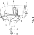
FIG. 9 is a perspective view of the support for the motor. -
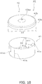
FIG. 10 is an exploded perspective view of a flame-retardant cover according to an embodiment. -
FIG. 11 is a perspective view of the flame-retardant cover according to the embodiment. -
FIG. 12 is an exploded perspective view of a flame-retardant cover according to a modification example 1A. -
FIG. 13 is a perspective view of the flame-retardant cover according to the modification example 1A. - A fan according to an embodiment of the present disclosure will now be described with reference to the drawings.
FIG. 1 depicts outer appearance of an air cleaner including the fan according to the embodiment. Anair cleaner 1 includes a resin housing 2 having a bottom provided with anintake port 3 and a top face provided with a blow-outport 4. -
FIG. 2 depicts a fan electromotor assembly that includes a motor provided with an impeller and is attached to a bottom plate.FIG. 3 depicts the fan diagonally viewed from a right upper front position.FIG. 3 depicts afan 10 provided with a side plate of a fan scroll.FIG. 4 depicts the fan viewed from backward. - The
fan 10 is provided with abottom plate 11 attached to a bottom face of theair cleaner 1. As depicted inFIG. 3 , the fan scroll includes anupper member 12 and aside plate 13 both attached to the assembly depicted inFIG. 2 . - The
fan 10 is a sirocco fan configured to suck air through anopening 14 provided in theside plate 13 and blow out air through anupper opening 15. - The
opening 14 and theopening 15 interpose animpeller 16 configured to rotate to generate an air flow from theopening 14 to theopening 15. Theimpeller 16 is a so-called sirocco fan rotor. - Amotor 31 (see
FIG. 5 ) includes adrive shaft 32 coupled to theimpeller 16 and rotates theimpeller 16. Themotor 31 is constituted by a DC electromotor or the like, and aharness 33 extends from themotor 31. - A
motor assembly 30 is supported by asupport 50 attached to thebottom plate 11. Theimpeller 16 is coupled to thedrive shaft 32, and thesupport 50 thus supports themotor 31 as well as theimpeller 16. - The
motor assembly 30 will be described in terms of its configuration with reference toFIG. 5 . Themotor assembly 30 includes themotor 31 and a flame-retardant cover 40.FIG. 5 depicts a frontcushion rubber member 51 that is included in thesupport 50. Themotor 31 includes thedrive shaft 32 and theharness 33. Themotor 31 includes atrunk 34 in a substantially cylindrical shape. Thetrunk 34 has such a substantially cylindrical shape, failing to have a perfect cylindrical shape due to a led portion of theharness 33 and unevenness of afront face 34a with thedrive shaft 32 protruding therefrom. However, thetrunk 34 has aside face 34b mostly having a cylindrical surface. In other words, themotor 31 has a cylindrical surface. Thefront face 34a and theside face 34b of thecylindrical trunk 34 each have a resin surface. Themotor 31 accordingly has a resin cylindrical surface. Thetrunk 34 has arear face 34c covered with a metal member. - The resin portion of the
trunk 34 is made of a thermosetting resin. Examples of the thermosetting resin for thetrunk 34 include an unsaturated polyester resin. Thetrunk 34 may be made of a bulk molding compound (BMC) mainly containing an unsaturated polyester resin. - The
trunk 34 of themotor 31 has aprotrusion 34d having a rectangular parallelepiped shape and allowing theharness 33 to be led out of theside face 34b. The flame-retardant cover 40 is thus shaped to be along theprotrusion 34d. - The flame-
retardant cover 40 includes acylindrical metal member 41 and ametal lid 42. Thecylindrical metal member 41 is in tight contact with theside face 34b of thetrunk 34 of themotor 31. Themetal lid 42 is fitted along an axis of themotor 31 and covers thefront face 34a of thetrunk 34. The flame-retardant cover 40 will be described later in terms of its detailed configuration. - Similarly to the
metal lid 42, the frontcushion rubber member 51 is fitted along the axis of themotor 31 after themetal lid 42 is fitted. With afan electromotor assembly 20 being completed, the frontcushion rubber member 51 inhibits themetal lid 42 from shifting away from thetrunk 34 of themotor 31. The frontcushion rubber member 51 inhibits themetal lid 42 from shifting away from thetrunk 34, so that themetal lid 42 simply fitted to thetrunk 34 will not be detached from thetrunk 34. - The
fan electromotor assembly 20 will be described in terms of its configuration with reference toFIG. 6 to FIG. 9 .FIG. 6 is an exploded perspective view of thefan electromotor assembly 20. Thefan electromotor assembly 20 is formed by assembling theimpeller 16, themotor assembly 30, and thesupport 50. Theimpeller 16 is fixed to thedrive shaft 32 of themotor 31 by means of anut 55 and aplain washer 56. - The
support 50 includes the frontcushion rubber member 51, a rearcushion rubber member 52, ametal fixture 53, and ametal attachment plate 54. Thefixture 53 is fixed to thebottom plate 11 by means of a screw 57 (seeFIG. 9 ). As depicted inFIG. 7 , thefixture 53 has acavity 53a extending forward and backward to be longer than thetrunk 34 of themotor 31. Thecavity 53a extends along a diameter of thetrunk 34 to be longer than total length of thetrunk 34 provided with themetal member 41. The cavity is provided such that thetrunk 34 in tight contact with themetal member 41 can be attached without contacting a side wall 53aa of the cavity. - As depicted in
FIG. 7 , therear face 34c of themotor 31 has a cylindrical projection 34ca which is protruding from therear face 34c. The rearcushion rubber member 52 has acylindrical hole 52a along the projection 34ca. The projection 34ca is fitted to thehole 52a to integrate themotor 31 with the rearcushion rubber member 52. - The
cavity 53a of thefixture 53 has an internal face provided with a cylindrical recess 53ab allowing an outline of the rearcushion rubber member 52 to be fitted thereto without clearance. The rearcushion rubber member 52 is fitted to the recess 52ab to allow the rearcushion rubber member 52 as well as a rear portion of themotor 31 to be fixed. - The
front face 34a of thetrunk 34 of themotor 31 has a cylindrical projection 34aa which is protruding from thefront face 34a. The frontcushion rubber member 51 has ahole 51a in a cylindrical shape along the projection 34aa. The projection 34aa of thetrunk 34 is fitted to thehole 51a to integrate themotor 31 with the frontcushion rubber member 51. - The
attachment plate 54 is provided with anopening 54a (seeFIG. 6 ) to which the frontcushion rubber member 51 is fitted. Theopening 54a has an inner diameter substantially equal to an outer diameter of the frontcushion rubber member 51. The frontcushion rubber member 51 as well as a front portion of themotor 31 are fixed when the frontcushion rubber member 51 is fitted to theopening 54a with the projection 34aa of themotor 31 being fitted to the frontcushion rubber member 51. - The
attachment plate 54 is fixed to thefixture 53 by means of threescrews 54b. The frontcushion rubber member 51 has aflange 51b (seeFIG. 5 ) interposed between theattachment plate 54 and thefront face 34a of thetrunk 34 of themotor 31. Theflange 51b is interposed between themetal lid 42 and theattachment plate 54, so that themetal lid 42 is fixed to thefixture 53 along with theattachment plate 54 without contacting theattachment plate 54. - In such a state where the
metal lid 42 and theattachment plate 54 are fixed to thefixture 53, theprotrusion 34d allowing theharness 33 to be led out is not in contact with thefixture 53. - As depicted in
FIG. 10 andFIG. 11 , themetal member 41 of the flame-retardant cover 40 has acylindrical portion 411 and aharness correspondence portion 412 having a C sectional shape. Thecylindrical portion 411 and theharness correspondence portion 412 are differentiated from each other by acircumferential cutout 41a. Thecutout 41a is sized to allow theprotrusion 34d having the rectangular parallelepiped shape and provided to lead out theharness 33 to be fitted to thecutout 41a without clearance. - The
metal member 41 comprises a thin metal sheet having a thickness of grater than or equal to 0.1 mm and less or equal to 0.5 mm and rolled. The thin metal sheet is preferred to be at least 0.2 mm thick to achieve a higher flame retardation function. The thin metal sheet may be made of stainless steel or the like. The stainless steel is preferred in terms of its rustproofness. Preferred examples of the stainless steel include austenitic stainless steel unlikely to be magnetized, such as SUS304. - The
metal member 41 is constituted by the thin metal sheet that has a substantially rectangular shape except for thecutout 41a. The thin metal sheet in the rectangular shape is wound to form themetal member 41. For example, the thin metal sheet may be wound to become spiral in such a state that no stress is applied. - The thin metal sheet spirally wound without any stress has a
first end 41m located outside and asecond end 41n located inside, as depicted inFIG. 10 . When the thin metal sheet is spirally wound to have the innerfirst end 41m and the outersecond end 41n overlapped with each other, themetal member 41 has a cylindrical shape as depicted inFIG. 10 . The cylindrical shape has a diameter D2 smaller than a diameter D1 (seeFIG. 5 ) of thetrunk 34 of themotor 31. - When the
metal member 41 is fitted to the cylindrical surface of thetrunk 34 of themotor 31, thecylindrical portion 411 being elastically deformed covers the cylindrical surface of thetrunk 34. Themetal member 41 fitted to the cylindrical surface of thetrunk 34 is in tight contact with the cylindrical surface due to force generated by elastic deformation. Even with thecylindrical portion 411 being elastically deformed, thefirst end 41m and thesecond end 41n are still overlapped with each other. When themetal member 41 in tight contact with the cylindrical surface still has such overlap, themetal member 41 covers the entire cylindrical surface of thetrunk 34. - The
metal lid 42 of the flame-retardant cover 40 includes anannular portion 42a as a metal annular portion, and adisc portion 42b as a metal disc portion. Theannular portion 42a has a diameter D3 larger than an outline of the cylindrical surface of thetrunk 34 to which themetal member 41 is fitted. Themetal lid 42 can thus be fitted from above thetrunk 34 to which themetal member 41 is fitted. Thedisc portion 42b has a center provided with an opening 42ba to which the projection 34aa of thetrunk 34 of themotor 31 is fitted. - The embodiment described above refers to the flame-
retardant cover 40 including themetal member 41 and themetal lid 42. As depicted inFIG. 12 andFIG. 13 , the flame-retardant cover 40 may further include ametal bottom portion 43. - The
metal bottom portion 43 is preferably provided in a case where therear face 34c of themotor 31 is partially made of resin. Similarly to themetal lid 42, themetal bottom portion 43 depicted inFIG. 12 includes anannular portion 43a as a metal annular portion, and adisc portion 43b as a metal disc portion. Theannular portion 43a is different from theannular portion 42a in that theannular portion 43a is provided with acutout 43c corresponding to thecutout 41a. - When the
annular portion 42a of themetal lid 42 has the diameter D3, theannular portion 43a of themetal bottom portion 43 may have the diameter D3. The diameter D3 of theannular portion 43a is larger than the outline of the cylindrical surface of thetrunk 34 to which themetal member 41 is fitted. Themetal bottom portion 43 can thus be fitted from above thetrunk 34 to which themetal member 41 is fitted. Thedisc portion 43b has a center provided with an opening 43ba to which the rear projection 34ca of thetrunk 34 of themotor 31 is fitted. - In a case where the motor has a metal front face, only the
metal bottom portion 43 may be provided, without providing themetal lid 42. - The above embodiment refers to the
fan 10 constituted as the sirocco fan. The fan, to which the technique according to the present disclosure is applicable, is not limited to the sirocco fan. The fan to which the technique according to the present disclosure is applicable may alternatively be constituted as a centrifugal fan other than the sirocco fan, or may be constituted as an axial fan, a mixed flow fan, or a cross-flow fan other than the centrifugal fan. - The
motor 31 according to the above embodiment is driven with DC voltage. The motor to which the technique of the present disclosure is applied is not necessarily driven with DC voltage but may alternatively be driven with AC voltage. - The
fan 10 according to the above embodiment includes theimpeller 16 constituted as the fan rotor. Thefan 10 may alternatively include any impeller other than the fan rotor. The technique according to the present disclosure is applicable to a fan including an impeller constituted as a propeller fan. - The above embodiment refers to the
fan 10 attached to theair cleaner 1. The fan according to the present disclosure is not limitedly attached to the air cleaner. - The
metal member 41 according to the above embodiment is made in tight contact with the cylindrical surface of thetrunk 34 of themotor 31 by elasticity of themetal member 41 and themetal lid 42 and/or themetal bottom portion 43 pressing themetal member 41. In order to achieve tighter contact between themetal member 41 and the cylindrical surface of thetrunk 34 without clearance, the flame-retardant cover may further include a tight binder fastening outer circumference of themetal member 41. Examples of the tight binder include a binding tape, a binding band, and a heat shrinkable tube. Examples of the binding tape include a filament tape provided with reinforcing fiber having high strength. Specifically, after themetal member 41 is wound around the cylindrical surface of thetrunk 34, the filament tape may be attached around an outer circumferential face of themetal member 41. The filament tape is preferably wound at least once around the outer circumferential face of themetal member 41. - As described above, the flame-
retardant cover 40 of thefan 10 is made of metal and includes themetal member 41 that is elastically deformed to be in tight contact with and cover the cylindrical surface of theresin trunk 34 of themotor 31, to achieve improvement in flame retardation function of themotor 31. Themetal member 41 of the flame-retardant cover 40 is elastically deformed to be in tight contact with thetrunk 34 of themotor 31, without need for any member achieving the tight contact. Thetabular metal member 41 can become a roll by winding a tabular thin metal sheet around a cylindrical member, for example. The metal flame-retardant cover 40 can thus be obtained without complicated metal drawing at a lower cost. Furthermore, the flame-retardant cover 40 is easily attached to themotor 31 to inhibit increase in assembling cost for thefan 10. Thecylindrical portion 411 of themetal member 41 of the flame-retardant cover 40 can thus be easily made in tight contact with the entire cylindrical surface of theresin trunk 34 of themotor 31, to achieve a high flame retardation function of thefan 10 at a low cost. - The
tabular metal member 41 is easily processed by winding the thin metal sheet made of stainless steel which has a thickness of grater than or equal to 0.1 mm and less than or equal to 0.5 mm. The flame-retardant cover 40 can thus be obtained at a low cost and thefan 10 achieves an excellent flame retardation function at a low cost. - The
metal lid 42 of the flame-retardant cover 40 is fitted along the axis of themotor 31 to prevent flaming along the axis of themotor 31 from the cylindrical surface of theresin trunk 34 of themotor 31, achieving improvement in flame retardation function of themotor 31. - The
annular portion 42a of themetal lid 42 is laid over thecylindrical portion 411 constituted by thetabular metal member 41 being simply wound, and theannular portion 42a can thus press thecylindrical portion 411. The attachedmetal lid 42 supports to keep the shape of thecylindrical portion 411 of the metal flame-retardant cover 40 and achieves reduction in the number of parts necessary for provision of the flame-retardant cover 40. - The
metal member 41 additionally has the simple structure of thecutout 41a to allow theharness 33 to be led out and allow the cylindrical surface of thetrunk 34 of themotor 31 around theharness 33 to be covered. This achieves structural simplification of the flame-retardant cover 40 of themotor 31 provided with theharness 33 led out of the cylindrical surface. This inhibits increase in cost for provision of the metal flame-retardant cover 40 along themotor 31 provided with theharness 33 led out of the cylindrical surface of theresin trunk 34. - The front
cushion rubber member 51, the rearcushion rubber member 52, thefixture 53, and theattachment plate 54 constituting the support are not in contact with thecylindrical portion 411 of the flame-retardant cover 40. Themotor 31 can thus be supported with no application of stress to the simply woundcylindrical portion 411 of the flame-retardant cover 40. This facilitates assembly to thefan 10, of themotor 31 provided with the metal flame-retardant cover 40 being elastically deformed to be in tight contact with themotor 31. - The embodiments of the present disclosure have been described above. Various modifications to modes and details will be available without departing from the object and the scope of the present disclosure recited in the claims.
-
- 10
- fan
- 16
- impeller
- 31
- motor
- 33
- harness
- 34
- trunk
- 40
- flame-retardant cover
- 41
- metal member
- 411
- cylindrical portion
- 41a
- cutout
- 42
- metal lid
- 42a
- annular portion
- 43
- metal bottom portion
- 50
- support
- 51
- front cushion rubber member
- 52
- rear cushion rubber member
- 53
- fixture
- 54
- attachment plate
- Patent Literature 1:
JP 2003-269385 A
Claims (7)
- A fan comprising:an impeller (16) configured to rotate to generate an air flow;a motor (31) having a resin cylindrical surface and configured to rotate the impeller; anda metal cover (40) including a tabular metal member (41) that has a cylindrical portion (411) wound to be smaller in diameter than the cylindrical surface of the motor and have ends overlapped with each other, and covering the cylindrical surface with the cylindrical portion being elastically deformed.
- The fan according to claim 1, wherein
the cover comprises a thin metal sheet having a thickness of greater than or equal to 0.1 mm and less than or equal to 0.5 mm and rolled as the cylindrical portion. - The fan according to claim 1 or 2, wherein
the cover further includes a metal lid (42) fitted along an axis of the motor. - The fan according to claim 3, wherein
the metal lid of the cover has an annular portion (42a) laid over the cylindrical portion of the metal member. - The fan according to any one of claims 1 to 4, whereinthe motor allows a harness (33) to be led out from the cylindrical surface at a position opposite to a position provided with the impeller, andthe metal member of the cover has a cutout (41a) positioned correspondingly to a led portion of the harness.
- The fan according to any one of claims 1 to 5, further comprising a support (50) covering the cylindrical portion of the cover.
- A flame-retardant cover of a fan motor (31) having a resin cylindrical surface and configured to rotate an impeller of a fan (10), the flame-retardant cover comprising:a tabular metal member (41) having a cylindrical portion (411) constituted by a thin metal sheet that has a thickness of grater than or equal to 0.1 mm and less than or equal to 0.5 mm, is wound to be smaller in diameter than the cylindrical surface of the motor, and has ends overlapped with each other, and covering the cylindrical surface with the cylindrical portion being elastically deformed; anda metal lid (42) having an annular portion (42a) and fitted along an axis of the motor to cause the annular portion to be laid over the cylindrical portion.
Applications Claiming Priority (2)
| Application Number | Priority Date | Filing Date | Title |
|---|---|---|---|
| JP2017147870A JP6414294B1 (en) | 2017-07-31 | 2017-07-31 | Flameproof cover for blower and motor |
| PCT/JP2018/027926 WO2019026727A1 (en) | 2017-07-31 | 2018-07-25 | Blower and fireproof cover for motor |
Publications (2)
| Publication Number | Publication Date |
|---|---|
| EP3664257A1 true EP3664257A1 (en) | 2020-06-10 |
| EP3664257A4 EP3664257A4 (en) | 2020-09-02 |
Family
ID=64017082
Family Applications (1)
| Application Number | Title | Priority Date | Filing Date |
|---|---|---|---|
| EP18842313.1A Withdrawn EP3664257A4 (en) | 2017-07-31 | 2018-07-25 | BLOWER AND FIRE-RESISTANT COVER FOR ENGINE |
Country Status (4)
| Country | Link |
|---|---|
| EP (1) | EP3664257A4 (en) |
| JP (1) | JP6414294B1 (en) |
| CN (1) | CN110720171B (en) |
| WO (1) | WO2019026727A1 (en) |
Families Citing this family (2)
| Publication number | Priority date | Publication date | Assignee | Title |
|---|---|---|---|---|
| CN111677694A (en) * | 2020-06-23 | 2020-09-18 | 惠州市奇思创想科技有限公司 | Centrifugal fire control smoke exhaust fan convenient to it is fixed |
| JP7748609B2 (en) * | 2022-01-18 | 2025-10-03 | 株式会社ノーリツ | Bathroom heating and drying equipment |
Family Cites Families (12)
| Publication number | Priority date | Publication date | Assignee | Title |
|---|---|---|---|---|
| JPS5317802U (en) * | 1976-07-23 | 1978-02-15 | ||
| JPS62159143U (en) * | 1986-03-26 | 1987-10-09 | ||
| JPH09261935A (en) * | 1996-03-19 | 1997-10-03 | Shibaura Eng Works Co Ltd | Brushless DC motor |
| JPH11285192A (en) * | 1998-03-30 | 1999-10-15 | Suzuki Motor Corp | Stator coating structure of portable generator |
| JP3777290B2 (en) * | 2000-06-14 | 2006-05-24 | 日本電産サンキョー株式会社 | motor |
| JP2003269385A (en) | 2002-03-14 | 2003-09-25 | Mitsubishi Electric Corp | Blower |
| CN102081975B (en) * | 2011-02-28 | 2013-04-03 | 北京京仪世纪电子股份有限公司 | Electric operator and wrapping cover thereof |
| JP2012222841A (en) * | 2011-04-04 | 2012-11-12 | Panasonic Corp | Motor and electric appliance equipped with the same |
| CN103997151B (en) * | 2014-05-17 | 2017-02-15 | 浙江格美机电科技有限公司 | Stainless steel motor with high weather resistance and high sealing performance |
| CN105099045A (en) * | 2015-09-15 | 2015-11-25 | 广东威灵电机制造有限公司 | Plastic package motor |
| CN105161355B (en) * | 2015-10-21 | 2018-09-07 | 广东威灵电机制造有限公司 | Motor protecter and plastic packaging motor |
| CN206287596U (en) * | 2016-10-25 | 2017-06-30 | 中国石油化工股份有限公司 | Anti- burning composite intermediate layer |
-
2017
- 2017-07-31 JP JP2017147870A patent/JP6414294B1/en active Active
-
2018
- 2018-07-25 CN CN201880038354.1A patent/CN110720171B/en active Active
- 2018-07-25 WO PCT/JP2018/027926 patent/WO2019026727A1/en not_active Ceased
- 2018-07-25 EP EP18842313.1A patent/EP3664257A4/en not_active Withdrawn
Also Published As
| Publication number | Publication date |
|---|---|
| CN110720171B (en) | 2021-06-29 |
| EP3664257A4 (en) | 2020-09-02 |
| JP6414294B1 (en) | 2018-10-31 |
| WO2019026727A1 (en) | 2019-02-07 |
| CN110720171A (en) | 2020-01-21 |
| JP2019030133A (en) | 2019-02-21 |
Similar Documents
| Publication | Publication Date | Title |
|---|---|---|
| US8668477B2 (en) | Series-connected fan unit | |
| US20090246028A1 (en) | Fan blade iron isolation | |
| US20100146769A1 (en) | Electric Motor Case With Folded Out Mounting Tabs And Economical Motor-Fan Module Packaging | |
| US20190101125A1 (en) | Ventilation system and method | |
| EP2292931A2 (en) | Hermetic type compressor | |
| CN206503769U (en) | Centrifugal fan | |
| JP2014017919A (en) | Rotary electric machine | |
| JP6414294B1 (en) | Flameproof cover for blower and motor | |
| JP2006292312A (en) | Top plate structure of a high-altitude air conditioner | |
| CN204442047U (en) | Motor Mount Kits and Ducted Air Conditioners | |
| WO2017169999A1 (en) | Decorative panel mounting structure | |
| CN105114360A (en) | Volute fan mounting structure and assembly method thereof | |
| CN211975823U (en) | Driving device and electric product | |
| US9219386B2 (en) | Motor's stator unit | |
| CN220748587U (en) | Ceiling fan mechanism and fan device | |
| EP3293858A1 (en) | Rotor for outer rotor brushless electric motor | |
| CN222785829U (en) | Motor components and air conditioners | |
| US20090028715A1 (en) | Impeller | |
| CN223424309U (en) | Axial flow fan blades and fan equipment | |
| CN222147289U (en) | External rotor motor | |
| JP5670833B2 (en) | Ventilation fan | |
| JP7858287B2 (en) | filter structure | |
| JP3180576B2 (en) | Blower insulation structure | |
| US20240396317A1 (en) | Adjustable sealed electrical box | |
| US20250158472A1 (en) | Electric motor |
Legal Events
| Date | Code | Title | Description |
|---|---|---|---|
| STAA | Information on the status of an ep patent application or granted ep patent |
Free format text: STATUS: THE INTERNATIONAL PUBLICATION HAS BEEN MADE |
|
| PUAI | Public reference made under article 153(3) epc to a published international application that has entered the european phase |
Free format text: ORIGINAL CODE: 0009012 |
|
| STAA | Information on the status of an ep patent application or granted ep patent |
Free format text: STATUS: REQUEST FOR EXAMINATION WAS MADE |
|
| 17P | Request for examination filed |
Effective date: 20191216 |
|
| AK | Designated contracting states |
Kind code of ref document: A1 Designated state(s): AL AT BE BG CH CY CZ DE DK EE ES FI FR GB GR HR HU IE IS IT LI LT LU LV MC MK MT NL NO PL PT RO RS SE SI SK SM TR |
|
| AX | Request for extension of the european patent |
Extension state: BA ME |
|
| A4 | Supplementary search report drawn up and despatched |
Effective date: 20200730 |
|
| RIC1 | Information provided on ipc code assigned before grant |
Ipc: F04D 29/00 20060101ALI20200724BHEP Ipc: F04D 25/08 20060101ALI20200724BHEP Ipc: H02K 7/14 20060101ALI20200724BHEP Ipc: H02K 5/04 20060101AFI20200724BHEP Ipc: F04D 29/62 20060101ALI20200724BHEP |
|
| DAV | Request for validation of the european patent (deleted) | ||
| DAX | Request for extension of the european patent (deleted) | ||
| GRAP | Despatch of communication of intention to grant a patent |
Free format text: ORIGINAL CODE: EPIDOSNIGR1 |
|
| STAA | Information on the status of an ep patent application or granted ep patent |
Free format text: STATUS: GRANT OF PATENT IS INTENDED |
|
| INTG | Intention to grant announced |
Effective date: 20210303 |
|
| STAA | Information on the status of an ep patent application or granted ep patent |
Free format text: STATUS: THE APPLICATION IS DEEMED TO BE WITHDRAWN |
|
| 18D | Application deemed to be withdrawn |
Effective date: 20210714 |