EP3664252A1 - Pre-charge resistor protective apparatus - Google Patents
Pre-charge resistor protective apparatus Download PDFInfo
- Publication number
- EP3664252A1 EP3664252A1 EP19748394.4A EP19748394A EP3664252A1 EP 3664252 A1 EP3664252 A1 EP 3664252A1 EP 19748394 A EP19748394 A EP 19748394A EP 3664252 A1 EP3664252 A1 EP 3664252A1
- Authority
- EP
- European Patent Office
- Prior art keywords
- precharge
- power
- processor
- precharge resistor
- protection apparatus
- Prior art date
- Legal status (The legal status is an assumption and is not a legal conclusion. Google has not performed a legal analysis and makes no representation as to the accuracy of the status listed.)
- Granted
Links
Images


Classifications
-
- H—ELECTRICITY
- H02—GENERATION; CONVERSION OR DISTRIBUTION OF ELECTRIC POWER
- H02J—ELECTRIC POWER NETWORKS; CIRCUIT ARRANGEMENTS OR SYSTEMS FOR SUPPLYING OR DISTRIBUTING ELECTRIC POWER; SYSTEMS FOR STORING ELECTRIC ENERGY
- H02J7/00—Circuit arrangements for charging or discharging batteries or for supplying loads from batteries
- H02J7/60—Circuit arrangements for charging or discharging batteries or for supplying loads from batteries including safety or protection arrangements
-
- H—ELECTRICITY
- H02—GENERATION; CONVERSION OR DISTRIBUTION OF ELECTRIC POWER
- H02J—ELECTRIC POWER NETWORKS; CIRCUIT ARRANGEMENTS OR SYSTEMS FOR SUPPLYING OR DISTRIBUTING ELECTRIC POWER; SYSTEMS FOR STORING ELECTRIC ENERGY
- H02J7/00—Circuit arrangements for charging or discharging batteries or for supplying loads from batteries
- H02J7/60—Circuit arrangements for charging or discharging batteries or for supplying loads from batteries including safety or protection arrangements
- H02J7/663—Circuit arrangements for charging or discharging batteries or for supplying loads from batteries including safety or protection arrangements using battery or load disconnect circuits
-
- H—ELECTRICITY
- H02—GENERATION; CONVERSION OR DISTRIBUTION OF ELECTRIC POWER
- H02J—ELECTRIC POWER NETWORKS; CIRCUIT ARRANGEMENTS OR SYSTEMS FOR SUPPLYING OR DISTRIBUTING ELECTRIC POWER; SYSTEMS FOR STORING ELECTRIC ENERGY
- H02J7/00—Circuit arrangements for charging or discharging batteries or for supplying loads from batteries
- H02J7/60—Circuit arrangements for charging or discharging batteries or for supplying loads from batteries including safety or protection arrangements
- H02J7/62—Circuit arrangements for charging or discharging batteries or for supplying loads from batteries including safety or protection arrangements against overcurrent
-
- B—PERFORMING OPERATIONS; TRANSPORTING
- B60—VEHICLES IN GENERAL
- B60L—PROPULSION OF ELECTRICALLY-PROPELLED VEHICLES; SUPPLYING ELECTRIC POWER FOR AUXILIARY EQUIPMENT OF ELECTRICALLY-PROPELLED VEHICLES; ELECTRODYNAMIC BRAKE SYSTEMS FOR VEHICLES IN GENERAL; MAGNETIC SUSPENSION OR LEVITATION FOR VEHICLES; MONITORING OPERATING VARIABLES OF ELECTRICALLY-PROPELLED VEHICLES; ELECTRIC SAFETY DEVICES FOR ELECTRICALLY-PROPELLED VEHICLES
- B60L3/00—Electric devices on electrically-propelled vehicles for safety purposes; Monitoring operating variables, e.g. speed, deceleration or energy consumption
- B60L3/0023—Detecting, eliminating, remedying or compensating for drive train abnormalities, e.g. failures within the drive train
- B60L3/0046—Detecting, eliminating, remedying or compensating for drive train abnormalities, e.g. failures within the drive train relating to electric energy storage systems, e.g. batteries or capacitors
-
- B—PERFORMING OPERATIONS; TRANSPORTING
- B60—VEHICLES IN GENERAL
- B60L—PROPULSION OF ELECTRICALLY-PROPELLED VEHICLES; SUPPLYING ELECTRIC POWER FOR AUXILIARY EQUIPMENT OF ELECTRICALLY-PROPELLED VEHICLES; ELECTRODYNAMIC BRAKE SYSTEMS FOR VEHICLES IN GENERAL; MAGNETIC SUSPENSION OR LEVITATION FOR VEHICLES; MONITORING OPERATING VARIABLES OF ELECTRICALLY-PROPELLED VEHICLES; ELECTRIC SAFETY DEVICES FOR ELECTRICALLY-PROPELLED VEHICLES
- B60L3/00—Electric devices on electrically-propelled vehicles for safety purposes; Monitoring operating variables, e.g. speed, deceleration or energy consumption
- B60L3/12—Recording operating variables ; Monitoring of operating variables
-
- G—PHYSICS
- G01—MEASURING; TESTING
- G01R—MEASURING ELECTRIC VARIABLES; MEASURING MAGNETIC VARIABLES
- G01R31/00—Arrangements for testing electric properties; Arrangements for locating electric faults; Arrangements for electrical testing characterised by what is being tested not provided for elsewhere
- G01R31/36—Arrangements for testing, measuring or monitoring the electrical condition of accumulators or electric batteries, e.g. capacity or state of charge [SoC]
- G01R31/382—Arrangements for monitoring battery or accumulator variables, e.g. SoC
-
- H—ELECTRICITY
- H02—GENERATION; CONVERSION OR DISTRIBUTION OF ELECTRIC POWER
- H02H—EMERGENCY PROTECTIVE CIRCUIT ARRANGEMENTS
- H02H1/00—Details of emergency protective circuit arrangements
- H02H1/0007—Details of emergency protective circuit arrangements concerning the detecting means
-
- H—ELECTRICITY
- H02—GENERATION; CONVERSION OR DISTRIBUTION OF ELECTRIC POWER
- H02H—EMERGENCY PROTECTIVE CIRCUIT ARRANGEMENTS
- H02H7/00—Emergency protective circuit arrangements specially adapted for specific types of electric machines or apparatus or for sectionalised protection of cable or line systems, and effecting automatic switching in the event of an undesired change from normal working conditions
- H02H7/18—Emergency protective circuit arrangements specially adapted for specific types of electric machines or apparatus or for sectionalised protection of cable or line systems, and effecting automatic switching in the event of an undesired change from normal working conditions for batteries; for accumulators
-
- H—ELECTRICITY
- H02—GENERATION; CONVERSION OR DISTRIBUTION OF ELECTRIC POWER
- H02H—EMERGENCY PROTECTIVE CIRCUIT ARRANGEMENTS
- H02H9/00—Emergency protective circuit arrangements for limiting excess current or voltage without disconnection
- H02H9/001—Emergency protective circuit arrangements for limiting excess current or voltage without disconnection limiting speed of change of electric quantities, e.g. soft switching on or off
- H02H9/002—Emergency protective circuit arrangements for limiting excess current or voltage without disconnection limiting speed of change of electric quantities, e.g. soft switching on or off limiting inrush current on switching on of inductive loads subjected to remanence, e.g. transformers
-
- B—PERFORMING OPERATIONS; TRANSPORTING
- B60—VEHICLES IN GENERAL
- B60L—PROPULSION OF ELECTRICALLY-PROPELLED VEHICLES; SUPPLYING ELECTRIC POWER FOR AUXILIARY EQUIPMENT OF ELECTRICALLY-PROPELLED VEHICLES; ELECTRODYNAMIC BRAKE SYSTEMS FOR VEHICLES IN GENERAL; MAGNETIC SUSPENSION OR LEVITATION FOR VEHICLES; MONITORING OPERATING VARIABLES OF ELECTRICALLY-PROPELLED VEHICLES; ELECTRIC SAFETY DEVICES FOR ELECTRICALLY-PROPELLED VEHICLES
- B60L2240/00—Control parameters of input or output; Target parameters
- B60L2240/40—Drive Train control parameters
- B60L2240/54—Drive Train control parameters related to batteries
- B60L2240/547—Voltage
-
- B—PERFORMING OPERATIONS; TRANSPORTING
- B60—VEHICLES IN GENERAL
- B60L—PROPULSION OF ELECTRICALLY-PROPELLED VEHICLES; SUPPLYING ELECTRIC POWER FOR AUXILIARY EQUIPMENT OF ELECTRICALLY-PROPELLED VEHICLES; ELECTRODYNAMIC BRAKE SYSTEMS FOR VEHICLES IN GENERAL; MAGNETIC SUSPENSION OR LEVITATION FOR VEHICLES; MONITORING OPERATING VARIABLES OF ELECTRICALLY-PROPELLED VEHICLES; ELECTRIC SAFETY DEVICES FOR ELECTRICALLY-PROPELLED VEHICLES
- B60L2240/00—Control parameters of input or output; Target parameters
- B60L2240/80—Time limits
-
- B—PERFORMING OPERATIONS; TRANSPORTING
- B60—VEHICLES IN GENERAL
- B60L—PROPULSION OF ELECTRICALLY-PROPELLED VEHICLES; SUPPLYING ELECTRIC POWER FOR AUXILIARY EQUIPMENT OF ELECTRICALLY-PROPELLED VEHICLES; ELECTRODYNAMIC BRAKE SYSTEMS FOR VEHICLES IN GENERAL; MAGNETIC SUSPENSION OR LEVITATION FOR VEHICLES; MONITORING OPERATING VARIABLES OF ELECTRICALLY-PROPELLED VEHICLES; ELECTRIC SAFETY DEVICES FOR ELECTRICALLY-PROPELLED VEHICLES
- B60L2260/00—Operating Modes
- B60L2260/40—Control modes
- B60L2260/44—Control modes by parameter estimation
-
- B—PERFORMING OPERATIONS; TRANSPORTING
- B60—VEHICLES IN GENERAL
- B60L—PROPULSION OF ELECTRICALLY-PROPELLED VEHICLES; SUPPLYING ELECTRIC POWER FOR AUXILIARY EQUIPMENT OF ELECTRICALLY-PROPELLED VEHICLES; ELECTRODYNAMIC BRAKE SYSTEMS FOR VEHICLES IN GENERAL; MAGNETIC SUSPENSION OR LEVITATION FOR VEHICLES; MONITORING OPERATING VARIABLES OF ELECTRICALLY-PROPELLED VEHICLES; ELECTRIC SAFETY DEVICES FOR ELECTRICALLY-PROPELLED VEHICLES
- B60L2270/00—Problem solutions or means not otherwise provided for
- B60L2270/20—Inrush current reduction, i.e. avoiding high currents when connecting the battery
-
- H—ELECTRICITY
- H02—GENERATION; CONVERSION OR DISTRIBUTION OF ELECTRIC POWER
- H02J—ELECTRIC POWER NETWORKS; CIRCUIT ARRANGEMENTS OR SYSTEMS FOR SUPPLYING OR DISTRIBUTING ELECTRIC POWER; SYSTEMS FOR STORING ELECTRIC ENERGY
- H02J2207/00—Details of circuit arrangements for charging or discharging batteries or supplying loads from batteries
- H02J2207/50—Charging of capacitors, supercapacitors, ultra-capacitors or double layer capacitors
Definitions
- the present disclosure relates to a precharge resistor protection apparatus, and more particularly, to a precharge resistor protection apparatus capable of diagnosing a precharge circuit unit by comparing an estimated power that is estimated as being supplied to the precharge circuit unit with a reference power range.
- Secondary batteries commercially available at the present include nickel-cadmium batteries, nickel hydrogen batteries, nickel-zinc batteries, lithium secondary batteries and the like.
- the lithium secondary batteries are in the limelight since they have almost no memory effect compared to nickel-based secondary batteries and also have very low self-discharging rate and high energy density.
- the secondary battery may be used as a single secondary battery, but in many cases, a plurality of secondary batteries are connected in series and/or in parallel in order to provide a high-voltage and/or large-capacity power storage system.
- the secondary battery may be used in the form of a battery pack, which includes a battery management device for controlling the charge and discharge operation of the secondary battery therein as a whole.
- a battery pack management device used in the battery pack monitors the state of the battery by using a temperature sensor, a current sensor, a voltage sensor or the like and uses the monitoring result to estimate SOC and SOH, balance the voltage between battery cells or protect the battery from high voltage, overcurrent, low temperature and high temperature.
- the battery pack management device may include a protection circuit to prevent overcurrent from flowing inside the battery pack.
- the battery pack management device includes a fuse on the charge and discharge path of the battery pack, and when overcurrent occurs, the battery pack management device cuts the fuse by melting to prevent overcurrent from flowing into the charge and discharge path of the battery pack.
- the battery pack management device may include a protection circuit for preventing a rush current, which is an overcurrent that may occur at the beginning of battery operation.
- the rush current is an overcurrent that may occur instantaneously at the beginning of battery operation, and a precharge resistor is frequently used to protect the battery pack from the rush current.
- FIG. 1 is a diagram schematically showing a conventional battery pack including a precharge circuit unit having a precharge resistor and a precharge relay.
- the battery pack includes a precharge circuit unit having a precharge resistor 20 and a precharge relay 40, a battery cell 10, and a main relay 30.
- the precharge resistor 20 is connected in parallel to a charge and discharge path of the battery pack
- the precharge relay 40 is connected in series to the precharge resistor 20
- the main relay 30 is provided on the charge and discharge path of the battery pack.
- the precharge relay 40 and the main relay 30 are switched to each other to prevent the occurrence of rush current.
- the main relay 30 is not turned on from the first, but the precharge relay 40 is turned on first in a state where the main relay 30 is turned off.
- the main relay 30 is turned on after a predetermined time from when the precharge relay 40 is turned on, so that the charge and discharge path may be connected to the main relay 30. In this case, since a current flows via the precharge resistor 20, rush current does not occur, and an arc is not generated when the main relay 30 turns on.
- overcurrent that may occur at the beginning of battery operation flows in the precharge resistor 20 frequently.
- the overcurrent flows in the precharge resistor 20 for a long time, the precharge resistor 20 is overheated, which may damage not only the precharge circuit unit but also the entire battery pack.
- the present disclosure is designed to solve the problems of the related art, and therefore the present disclosure is directed to providing a precharge resistor protection apparatus, which may protect a precharge resistor when a power over an allowable power level is supplied to the precharge resistor by comparing a reference power according to a first power estimated as being supplied to the precharge resistor with a second power actually supplied to the precharge resistor and controlling the operation state of the precharge relay based on the comparison result.
- a precharge resistor protection apparatus which protects a precharge resistor that is connected in series to a precharge relay to be included in a precharge circuit unit together with the precharge relay and also connected in parallel to a main relay provided to a charge and discharge path of a battery pack
- the precharge resistor protection apparatus comprising: a sensing unit configured to measure a battery voltage applied to both ends of a battery cell included in the battery pack and a precharge current flowing in the precharge resistor; and a processor operably coupled to the sensing unit.
- the processor may calculate a first power estimated as being supplied to the precharge resistor and a second power supplied to the precharge resistor during a driving time of the precharge circuit unit by using at least one of a capacitance of a capacitor connected to both ends of the battery pack, the battery voltage and the precharge current, compare a reference power range according to the first power with the second power, and control an operation state of the precharge relay based on the comparison result.
- W1 is the first power
- T1 is a start point of the driving time
- T2 is an end point of the driving time
- Vb(T1) is the battery voltage measured at the start point of the driving time
- R is a resistance of the precharge resistor
- C is the capacitance of the capacitor.
- the processor may calculate the driving time as a time difference between a first time point at which a turn-on control signal for controlling the operation state of the precharge relay into a turn-on state is output and a second time point at which a turn-off control signal for controlling the operation state of the precharge relay into a turn-off state is output.
- the processor may calculate the second power supplied to the precharge resistor during the driving time by using the precharge current and the battery voltage.
- W2 is the second power
- T1 is a start point of the driving time
- T2 is an end point of the driving time
- Vb(t) is the battery voltage
- Ir(t) is the precharge current
- the processor may set a first reference power range and a second reference power range lower than the first reference power range by using the first power.
- the processor may diagnose that a circuit connected to the capacitor is shorted, when the second power is included in the first reference power range according to the comparison result.
- the processor may diagnose that both ends of the battery pack are opened, when the second power is included in the second reference power range according to the comparison result.
- the processor may control the operation state of at least one of the precharge relay and the main relay into a turn-off state, when the second power is included in the first reference power range or the second reference power range according to the comparison result.
- a battery management device may comprise the precharge resistor protection apparatus.
- a battery pack according to the present disclosure may comprise the precharge resistor protection apparatus.
- a precharge resistor when a power over an allowable power level is supplied to the precharge resistor by comparing a reference power according to a first power estimated as being supplied to the precharge resistor with a second power actually supplied to the precharge resistor and controlling the operation state of the precharge relay based on the comparison result.
- present disclosure may have various other effects, and these other effects of the present disclosure can be understood by the following description and more clearly understood by the embodiments of the present disclosure.
- FIG. 2 is a block diagram schematically showing a precharge resistor protection apparatus 100 according to an embodiment of the present disclosure
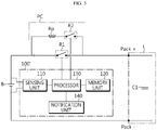
- FIG. 3 is a diagram schematically showing a connection configuration among the precharge resistor protection apparatus 100 according to an embodiment of the present disclosure, a battery pack and a load L.
- the precharge resistor protection apparatus 100 may protect a precharge resistor Rp provided in a precharge circuit unit PC that is included in a battery pack.
- the battery pack including the precharge resistor protection apparatus 100 may have a main relay R1 provided to a charge and discharge path and a precharge circuit unit PC connected in parallel to the main relay R1.
- the precharge circuit unit PC may have a precharge resistor Rp and a precharge relay R2 connected in series to each other.
- the battery pack may include one or more battery cells, and the plurality of battery cells may be connected in series and/or in parallel. In the present disclosure, the plurality of battery cells will be modeled as one equivalent battery cell B.
- a load L may be connected to both ends of the battery pack, namely to an output terminal, and the load L may have a capacitor Cl connected in parallel to the output terminal. That is, both ends of the capacitor Cl may be connected to both ends of the battery pack.
- the capacitor Cl may refer to an element having a capacitance and satisfying Equation 1 below.
- I C dv / dt
- I a current flowing in the capacitor
- V a voltage at both ends of the capacitor
- t time
- the capacitor Cl may be implemented not only as a single capacitor but also as a combination of a plurality of capacitors, and may also be implemented as a combination of passive elements and active elements different from each other.
- the capacitance C of the capacitor Cl is not limited and may have an optimal value selected in consideration of the voltage at both ends of the battery pack. Meanwhile, it is preferable that the capacitance C of the capacitor C1 is known in advance or is easily measured.
- the precharge resistor protection apparatus 100 may include a sensing unit 110, a memory unit 120, a processor 130, and a notification unit 140.
- the sensing unit 110 is operably coupled to the processor 130. That is, the sensing unit 110 may be connected to the processor 130 to transmit an electrical signal to the processor 130 or to receive an electrical signal from the processor 130.
- the sensing unit 110 may measure data that is used for the processor 130 to estimate a first power and calculate a second power, explained later.
- the sensing unit 110 may repeatedly measure a battery voltage applied to both ends of the battery cell B and a precharge current flowing in the precharge resistor Rp at predetermined intervals and provide a measurement signal indicating the measured battery voltage and precharge current to the processor 130 .
- the sensing unit 110 may include a voltage sensor configured to measure a battery voltage applied to both ends of the battery cell B. Also, the sensing unit 110 further includes a current sensor configured to measure a precharge current flowing in the precharge resistor Rp.
- the processor 130 may determine digital values of the battery voltage and the precharge current, respectively, through signal processing and then store the digital values in the memory unit 120.
- the memory unit 120 is a semiconductor memory device that records, erases and updates data generated by the processor 130, and stores a plurality of program codes prepared for protecting the precharge resistor Rp.
- the memory unit 120 may store preset values of various predetermined parameters used in implementing the present disclosure.
- the memory unit 120 may is not particularly limited as long as it is a semiconductor memory element known in the art as being capable of recording, erasing and updating data.
- the memory unit 120 may be DRAM, SDRAM, a flash memory, ROM, EEPROM, a register, and the like.
- the memory unit 120 may further include a storage medium that stores program codes defining the control logics of the processor 130.
- the storage medium includes a non-volatile storage element such as a flash memory or a hard disk.
- the memory unit 120 may be physically separate from the processor 130 or may be integrated with the processor 130.
- the processor 130 may estimate the first power estimated as being supplied to the precharge resistor Rp during a driving time of a precharge circuit unit PC by using the capacitance of the capacitor C1 connected to both ends of the battery pack and the battery voltage.
- the processor 130 may control the operation state of the main relay R1 into a turn-off state and control the operation state of the precharge relay R2 into a turn-on state. Accordingly, the voltage of the battery cell B may be applied to the capacitor Cl of the load L via the precharge circuit unit PC. In addition, the current may flow through the precharge circuit unit PC. That is, the current may also flow through the precharge resistor Rp provided in the precharge circuit unit PC.
- the processor 130 may control the operation state of the precharge relay R2 into a turn-off state. Accordingly, the voltage of the battery cell B may not be applied to the precharge circuit unit PC and the capacitor Cl of the load L. Also, the current may not flow in the precharge circuit unit PC. That is, the current may not also flow through the precharge resistor Rp provided in the precharge circuit unit PC.
- the processor 130 may calculate the driving time as a time difference between a first time point at which a turn-on control signal for controlling the operation state of the precharge relay R2 into a turn-on state is output and a second time point at which a turn-off control signal for controlling the operation state of the precharge relay R2 into a turn-off state is output.
- the first time point and the second time point may be a start point and an end point of the driving time of the precharge circuit unit PC, respectively.
- the processor 130 may calculate the time during which the current flows through the precharge resistor Rp as the driving time.
- the processor 130 may estimate the first power estimated as being supplied to the precharge resistor Rp during the driving time of the precharge circuit unit PC by using the capacitance of the capacitor C1 connected to both ends of the battery pack and the battery voltage.
- the first power may be a power estimated in a state where the capacitor Cl of the load L is normally connected to both ends of the battery pack and a short circuit failure or an open failure does not occur in the circuit connected to the precharge circuit unit PC and the capacitor Cl of the load L.
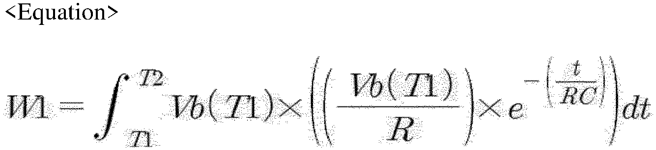
- the processor 130 may calculate the first power by using Equation 2 below.
- W 1 ⁇ T 1 T 2 Vb T 1 ⁇ Vb T 1 R ⁇ e ⁇ t RC dt
- T1 is a start point of the driving time
- T2 is an end point of the driving time
- Vb(T1) is the battery voltage measured at the start point of the driving time
- R is a resistance of the precharge resistor
- C is a capacitance of the capacitor.
- the operation state of the precharge relay R2 is controlled into a turn-on state and the operation state of the main relay R1 is controlled into a turn-off state, it is possible to form an RC circuit that has the precharge resistor Rp and the capacitor Cl and uses the battery cell B as a voltage source.
- the processor 130 may calculate and estimate the first power by multiplying the battery voltage by the calculated value of the current calculation equation for the capacitor Cl corresponding to the RC circuit during the driving time of the precharge circuit unit PC.
- the processor 130 may set a first reference power range and a second reference power range by using the calculated first power.
- the second reference power range may be set lower than the first reference power range.
- the processor 130 may set the first reference power range to be more than double of the calculated first power.
- the processor 130 may set the second reference power range to be less than half of the calculated first power.
- the processor 130 may calculate the second power supplied to the precharge resistor Rp during the driving time of the precharge circuit unit PC by using the precharge current and the battery voltage.
- the second power may refer a power actually supplied to the precharge resistor Rp during the driving time of the precharge circuit unit PC.
- the processor 130 may calculate the second power by using Equation 3 below.
- W 2 ⁇ T 1 T 2 Vb t ⁇ Ir t dt
- T1 is a start point of the driving time
- T2 is an end point of the driving time
- Vb(t) is the battery voltage
- Ir(t) is the precharge current
- the processor 130 compares the second power with the reference power range (the first reference power range and the second reference power range) will be described.
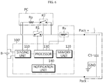
- FIG. 4 is a diagram for illustrating a process in which the precharge resistor protection apparatus 100 according to an embodiment of the present disclosure diagnoses whether a circuit connected to the capacitor C1 is shorted.
- the processor 130 may diagnose that the circuit connected to the capacitor Cl is shorted, if the estimated second power is included in the first reference power range. More specifically, as shown in FIG. 4 , if the circuit connected to the capacitor Cl is shorted to the ground GND, the power over an allowed power level may be supplied to the precharge resistor Rp.
- the second power which is the power actually supplied to the precharge resistor Rp, may be included in the first reference power range that is set to more than double of the first power.
- the processor 130 may diagnose that the circuit connected to the capacitor Cl is shorted, if the estimated second power is included in the first reference power range.
- the processor 130 may control the operation state of the precharge relay R2 into a turn-off state, if the estimated second power is included in the first reference power range. By doing so, the processor 130 allows the precharge resistor Rp not to be supplied with power any more, thereby preventing the precharge resistor Rp from being damaged.
- the processor 130 may control the operation state of the main relay R1 into a turn-off state, if the estimated second power is included in the first reference power range. By doing so, the processor 130 may allow the battery cell B not to be shorted to the ground GND, thereby preventing the battery cell B from being discharged as the voltage of the battery cell B is applied to the ground GND.
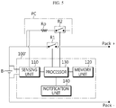
- FIG. 5 is a diagram for illustrating a process in which the precharge resistor protection apparatus 100 according to an embodiment of the present disclosure diagnoses whether both ends of the battery pack are opened.
- the processor 130 may diagnose that both ends of the battery pack are opened, if the estimated second power is included in the second reference power range. More specifically, as shown in FIG. 5 , if the capacitor Cl of the load L is not connected to both ends of the battery pack, both ends of the battery pack may be opened so that the current may not flow through the precharge resistor Rp.
- the second power which is a power actually supplied to the precharge resistor Rp, may be included in the second reference power range that is set to be less than half of the first power.
- the processor 130 may diagnose that both ends of the battery pack are opened, if the estimated second power is included in the second reference power range.
- the processor 130 may control the operation state of the precharge relay R2 and the main relay R1 into a turn-off state, if the estimated second power is included in the second reference power range. By doing so, the processor 130 may prevent a worker or a user from being electrically shocked as the current of the battery pack is leaked to both open ends of the battery pack.
- the processor 130 may selectively include an application-specific integrated circuit (ASIC), another chipset, a logic circuit, a register, a communication modem, and a data processing device. At least one of the various control logics executable by the processor 130 may be combined, and the combined control logic is written in a computer-readable code system and recorded on a computer-readable recording medium.
- the recording medium has no limitation as long as it can be accessed by the processor 130 included in a computer.
- the recording medium includes at least one selected from the group consisting of a ROM, a RAM, a register, a CD-ROM, a magnetic tape, a hard disk, a floppy disk and an optical data recording device.
- the code system may be modulated into a carrier signal and stored in a communication carrier at a specific time, and may be stored and executed in a distributed manner on computers connected through a network.
- functional programs, code and segments for implementing the combined control logics may be easily inferred by programmers in the technical field to which the present disclosure belongs.
- the notification unit 140 may receive the diagnosis result of the processor 130 from the processor 130 or output the diagnosis result of the processor 130 stored in the memory unit 120 to the outside.
- the notification unit 140 may include at least one of a display unit for displaying the diagnosis result of the processor 130 by using at least one of symbols, numbers and codes, and a speaker unit for outputting the diagnosis result of the processor 130 with a sound.
- FIG. 6 is a diagram schematically showing a connection configuration among the precharge resistor protection apparatus 100' according to another embodiment of the present disclosure, the battery pack and the load L.
- the precharge resistor protection apparatus 100' is substantially identical to the precharge resistor protection apparatus 100 of the former embodiment, except that a variable resistor Rv is further provided to the charge and discharge path of the battery pack. Thus, repeated description will be omitted.
- the variable resistor Rv may be a resistance element whose resistance is changed under the control of the processor 130.
- the type of the variable resistor Rv is not limited as long as the resistance changes corresponding to the control signal of the processor 130.
- the processor 130 may control the variable resistor Rv to change the resistance of the variable resistor Rv into a minimum resistance before the circuit connected to the capacitor Cl is diagnosed as being shorted.
- the processor 130 may diagnose that the circuit connected to the capacitor C1 is shorted to the ground GND, if the second power described above is included in the first reference power range.
- the processor 130 may control the variable resistor Rv to increase the resistance of the variable resistor Rv, if the circuit connected to the capacitor Cl is diagnosed as being shorted to the ground GND.
- the processor 130 may control the variable resistor Rv to increase the resistance of the variable resistor Rv corresponding to the battery voltage.
- the precharge resistor protection apparatus according to the present disclosure may be applied to a battery management device for managing a battery, such as a battery pack and an energy storage device. That is, the battery management device according to the present disclosure may include the precharge resistor protection apparatus according to the present disclosure.
Landscapes
- Engineering & Computer Science (AREA)
- Power Engineering (AREA)
- Physics & Mathematics (AREA)
- General Physics & Mathematics (AREA)
- Life Sciences & Earth Sciences (AREA)
- Sustainable Development (AREA)
- Sustainable Energy (AREA)
- Transportation (AREA)
- Mechanical Engineering (AREA)
- Charge And Discharge Circuits For Batteries Or The Like (AREA)
- Secondary Cells (AREA)
Abstract
Description
- The present application claims priority to Korean Patent Application No.
10-2018-0011458 filed on January 30, 2018 - The present disclosure relates to a precharge resistor protection apparatus, and more particularly, to a precharge resistor protection apparatus capable of diagnosing a precharge circuit unit by comparing an estimated power that is estimated as being supplied to the precharge circuit unit with a reference power range.
- Recently, the demand for portable electronic products such as notebook computers, video cameras and portable telephones has increased sharply, and electric vehicles, energy storage batteries, robots, satellites and the like have been developed in earnest. Accordingly, high-performance secondary batteries allowing repeated charging and discharging are being actively studied.
- Secondary batteries commercially available at the present include nickel-cadmium batteries, nickel hydrogen batteries, nickel-zinc batteries, lithium secondary batteries and the like. Among them, the lithium secondary batteries are in the limelight since they have almost no memory effect compared to nickel-based secondary batteries and also have very low self-discharging rate and high energy density.
- Meanwhile, the secondary battery may be used as a single secondary battery, but in many cases, a plurality of secondary batteries are connected in series and/or in parallel in order to provide a high-voltage and/or large-capacity power storage system. Also, the secondary battery may be used in the form of a battery pack, which includes a battery management device for controlling the charge and discharge operation of the secondary battery therein as a whole.
- A battery pack management device used in the battery pack monitors the state of the battery by using a temperature sensor, a current sensor, a voltage sensor or the like and uses the monitoring result to estimate SOC and SOH, balance the voltage between battery cells or protect the battery from high voltage, overcurrent, low temperature and high temperature.
- In particular, the battery pack management device may include a protection circuit to prevent overcurrent from flowing inside the battery pack. For example, the battery pack management device includes a fuse on the charge and discharge path of the battery pack, and when overcurrent occurs, the battery pack management device cuts the fuse by melting to prevent overcurrent from flowing into the charge and discharge path of the battery pack.
- In addition, the battery pack management device may include a protection circuit for preventing a rush current, which is an overcurrent that may occur at the beginning of battery operation. Here, the rush current is an overcurrent that may occur instantaneously at the beginning of battery operation, and a precharge resistor is frequently used to protect the battery pack from the rush current.
-
FIG. 1 is a diagram schematically showing a conventional battery pack including a precharge circuit unit having a precharge resistor and a precharge relay. Referring toFIG. 1 , the battery pack includes a precharge circuit unit having aprecharge resistor 20 and aprecharge relay 40, abattery cell 10, and amain relay 30. Here, theprecharge resistor 20 is connected in parallel to a charge and discharge path of the battery pack, theprecharge relay 40 is connected in series to theprecharge resistor 20, and themain relay 30 is provided on the charge and discharge path of the battery pack. Theprecharge relay 40 and themain relay 30 are switched to each other to prevent the occurrence of rush current. - In particular, at the beginning of battery operation, the
main relay 30 is not turned on from the first, but theprecharge relay 40 is turned on first in a state where themain relay 30 is turned off. In addition, themain relay 30 is turned on after a predetermined time from when theprecharge relay 40 is turned on, so that the charge and discharge path may be connected to themain relay 30. In this case, since a current flows via theprecharge resistor 20, rush current does not occur, and an arc is not generated when themain relay 30 turns on. - As described above, overcurrent that may occur at the beginning of battery operation flows in the
precharge resistor 20 frequently. Here, if the overcurrent flows in theprecharge resistor 20 for a long time, theprecharge resistor 20 is overheated, which may damage not only the precharge circuit unit but also the entire battery pack. - The present disclosure is designed to solve the problems of the related art, and therefore the present disclosure is directed to providing a precharge resistor protection apparatus, which may protect a precharge resistor when a power over an allowable power level is supplied to the precharge resistor by comparing a reference power according to a first power estimated as being supplied to the precharge resistor with a second power actually supplied to the precharge resistor and controlling the operation state of the precharge relay based on the comparison result.
- These and other objects and advantages of the present disclosure may be understood from the following detailed description and will become more fully apparent from the exemplary embodiments of the present disclosure. Also, it will be easily understood that the objects and advantages of the present disclosure may be realized by the means shown in the appended claims and combinations thereof.
- In one aspect of the present disclosure, there is provided a precharge resistor protection apparatus, which protects a precharge resistor that is connected in series to a precharge relay to be included in a precharge circuit unit together with the precharge relay and also connected in parallel to a main relay provided to a charge and discharge path of a battery pack, the precharge resistor protection apparatus comprising: a sensing unit configured to measure a battery voltage applied to both ends of a battery cell included in the battery pack and a precharge current flowing in the precharge resistor; and a processor operably coupled to the sensing unit.
- Preferably, the processor may calculate a first power estimated as being supplied to the precharge resistor and a second power supplied to the precharge resistor during a driving time of the precharge circuit unit by using at least one of a capacitance of a capacitor connected to both ends of the battery pack, the battery voltage and the precharge current, compare a reference power range according to the first power with the second power, and control an operation state of the precharge relay based on the comparison result.
- Preferably, the processor may calculate the first power by using the equation below:
- Preferably, the processor may calculate the driving time as a time difference between a first time point at which a turn-on control signal for controlling the operation state of the precharge relay into a turn-on state is output and a second time point at which a turn-off control signal for controlling the operation state of the precharge relay into a turn-off state is output.
- Preferably, the processor may calculate the second power supplied to the precharge resistor during the driving time by using the precharge current and the battery voltage.
- Preferably, the processor may calculate the second power by using the equation below:

- Preferably, the processor may set a first reference power range and a second reference power range lower than the first reference power range by using the first power.
- Preferably, the processor may diagnose that a circuit connected to the capacitor is shorted, when the second power is included in the first reference power range according to the comparison result.
- Preferably, the processor may diagnose that both ends of the battery pack are opened, when the second power is included in the second reference power range according to the comparison result.
- Preferably, the processor may control the operation state of at least one of the precharge relay and the main relay into a turn-off state, when the second power is included in the first reference power range or the second reference power range according to the comparison result.
- A battery management device according to the present disclosure may comprise the precharge resistor protection apparatus.
- A battery pack according to the present disclosure may comprise the precharge resistor protection apparatus.
- According to the present disclosure, it is possible to protect a precharge resistor when a power over an allowable power level is supplied to the precharge resistor by comparing a reference power according to a first power estimated as being supplied to the precharge resistor with a second power actually supplied to the precharge resistor and controlling the operation state of the precharge relay based on the comparison result.
- In addition, the present disclosure may have various other effects, and these other effects of the present disclosure can be understood by the following description and more clearly understood by the embodiments of the present disclosure.
- The accompanying drawings illustrate a preferred embodiment of the present disclosure and together with the foregoing disclosure, serve to provide further understanding of the technical features of the present disclosure, and thus, the present disclosure is not construed as being limited to the drawing.
-
FIG. 1 is a diagram schematically showing a conventional battery pack including a precharge circuit unit. -
FIG. 2 is a block diagram schematically showing a precharge resistor protection apparatus according to an embodiment of the present disclosure. -
FIG. 3 is a diagram schematically showing a connection configuration among the precharge resistor protection apparatus according to an embodiment of the present disclosure, a battery pack and a load. -
FIG. 4 is a diagram for illustrating a process in which the precharge resistor protection apparatus according to an embodiment of the present disclosure diagnoses whether a circuit connected to a capacitor is shorted. -
FIG. 5 is a diagram for illustrating a process in which the precharge resistor protection apparatus according to an embodiment of the present disclosure diagnoses whether both ends of the battery pack are opened. -
FIG. 6 is a diagram schematically showing a connection configuration among the precharge resistor protection apparatus according to another embodiment of the present disclosure, the battery pack and the load. - Hereinafter, preferred embodiments of the present disclosure will be described in detail with reference to the accompanying drawings. Prior to the description, it should be understood that the terms used in the specification and the appended claims should not be construed as limited to general and dictionary meanings, but interpreted based on the meanings and concepts corresponding to technical aspects of the present disclosure on the basis of the principle that the inventor is allowed to define terms appropriately for the best explanation.
- Therefore, the description proposed herein is just a preferable example for the purpose of illustrations only, not intended to limit the scope of the disclosure, so it should be understood that other equivalents and modifications could be made thereto without departing from the scope of the disclosure.
- Additionally, in describing the present disclosure, when it is deemed that a detailed description of relevant known elements or functions renders the key subject matter of the present disclosure ambiguous, the detailed description is omitted herein.
-
FIG. 2 is a block diagram schematically showing a prechargeresistor protection apparatus 100 according to an embodiment of the present disclosure, andFIG. 3 is a diagram schematically showing a connection configuration among the prechargeresistor protection apparatus 100 according to an embodiment of the present disclosure, a battery pack and a load L. - Referring to
FIGS. 2 and3 , the prechargeresistor protection apparatus 100 according to an embodiment of the present disclosure may protect a precharge resistor Rp provided in a precharge circuit unit PC that is included in a battery pack. - The battery pack including the precharge
resistor protection apparatus 100 according to an embodiment of the present disclosure may have a main relay R1 provided to a charge and discharge path and a precharge circuit unit PC connected in parallel to the main relay R1. The precharge circuit unit PC may have a precharge resistor Rp and a precharge relay R2 connected in series to each other. Also, the battery pack may include one or more battery cells, and the plurality of battery cells may be connected in series and/or in parallel. In the present disclosure, the plurality of battery cells will be modeled as one equivalent battery cell B. - Meanwhile, a load L may be connected to both ends of the battery pack, namely to an output terminal, and the load L may have a capacitor Cl connected in parallel to the output terminal. That is, both ends of the capacitor Cl may be connected to both ends of the battery pack.
- The capacitor Cl may refer to an element having a capacitance and satisfying Equation 1 below.

- In addition, the capacitor Cl may be implemented not only as a single capacitor but also as a combination of a plurality of capacitors, and may also be implemented as a combination of passive elements and active elements different from each other. In addition, the capacitance C of the capacitor Cl is not limited and may have an optimal value selected in consideration of the voltage at both ends of the battery pack. Meanwhile, it is preferable that the capacitance C of the capacitor C1 is known in advance or is easily measured.
- Referring to
FIGS. 2 and3 again, the prechargeresistor protection apparatus 100 according to an embodiment of the present disclosure may include asensing unit 110, amemory unit 120, aprocessor 130, and anotification unit 140. - The
sensing unit 110 is operably coupled to theprocessor 130. That is, thesensing unit 110 may be connected to theprocessor 130 to transmit an electrical signal to theprocessor 130 or to receive an electrical signal from theprocessor 130. - The
sensing unit 110 may measure data that is used for theprocessor 130 to estimate a first power and calculate a second power, explained later. - To this end, the
sensing unit 110 may repeatedly measure a battery voltage applied to both ends of the battery cell B and a precharge current flowing in the precharge resistor Rp at predetermined intervals and provide a measurement signal indicating the measured battery voltage and precharge current to theprocessor 130 . - The
sensing unit 110 may include a voltage sensor configured to measure a battery voltage applied to both ends of the battery cell B. Also, thesensing unit 110 further includes a current sensor configured to measure a precharge current flowing in the precharge resistor Rp. - If a measurement signal is received from the
sensing unit 110, theprocessor 130 may determine digital values of the battery voltage and the precharge current, respectively, through signal processing and then store the digital values in thememory unit 120. - The
memory unit 120 is a semiconductor memory device that records, erases and updates data generated by theprocessor 130, and stores a plurality of program codes prepared for protecting the precharge resistor Rp. In addition, thememory unit 120 may store preset values of various predetermined parameters used in implementing the present disclosure. - The
memory unit 120 may is not particularly limited as long as it is a semiconductor memory element known in the art as being capable of recording, erasing and updating data. For example, thememory unit 120 may be DRAM, SDRAM, a flash memory, ROM, EEPROM, a register, and the like. In addition, thememory unit 120 may further include a storage medium that stores program codes defining the control logics of theprocessor 130. The storage medium includes a non-volatile storage element such as a flash memory or a hard disk. Thememory unit 120 may be physically separate from theprocessor 130 or may be integrated with theprocessor 130. - The
processor 130 may estimate the first power estimated as being supplied to the precharge resistor Rp during a driving time of a precharge circuit unit PC by using the capacitance of the capacitor C1 connected to both ends of the battery pack and the battery voltage. - In order to drive the precharge circuit unit PC, the
processor 130 may control the operation state of the main relay R1 into a turn-off state and control the operation state of the precharge relay R2 into a turn-on state. Accordingly, the voltage of the battery cell B may be applied to the capacitor Cl of the load L via the precharge circuit unit PC. In addition, the current may flow through the precharge circuit unit PC. That is, the current may also flow through the precharge resistor Rp provided in the precharge circuit unit PC. - After that, in order to terminate the operation of the precharge circuit unit PC, the
processor 130 may control the operation state of the precharge relay R2 into a turn-off state. Accordingly, the voltage of the battery cell B may not be applied to the precharge circuit unit PC and the capacitor Cl of the load L. Also, the current may not flow in the precharge circuit unit PC. That is, the current may not also flow through the precharge resistor Rp provided in the precharge circuit unit PC. - At this time, the
processor 130 may calculate the driving time as a time difference between a first time point at which a turn-on control signal for controlling the operation state of the precharge relay R2 into a turn-on state is output and a second time point at which a turn-off control signal for controlling the operation state of the precharge relay R2 into a turn-off state is output. At this time, the first time point and the second time point may be a start point and an end point of the driving time of the precharge circuit unit PC, respectively. - That is, the
processor 130 may calculate the time during which the current flows through the precharge resistor Rp as the driving time. - In this way, the
processor 130 may estimate the first power estimated as being supplied to the precharge resistor Rp during the driving time of the precharge circuit unit PC by using the capacitance of the capacitor C1 connected to both ends of the battery pack and the battery voltage. - The first power may be a power estimated in a state where the capacitor Cl of the load L is normally connected to both ends of the battery pack and a short circuit failure or an open failure does not occur in the circuit connected to the precharge circuit unit PC and the capacitor Cl of the load L.
- At this time, the
processor 130 may calculate the first power by usingEquation 2 below.
- More specifically, if the operation state of the precharge relay R2 is controlled into a turn-on state and the operation state of the main relay R1 is controlled into a turn-off state, it is possible to form an RC circuit that has the precharge resistor Rp and the capacitor Cl and uses the battery cell B as a voltage source.
- By using this, the
processor 130 may calculate and estimate the first power by multiplying the battery voltage by the calculated value of the current calculation equation for the capacitor Cl corresponding to the RC circuit during the driving time of the precharge circuit unit PC. - After that, the
processor 130 may set a first reference power range and a second reference power range by using the calculated first power. Here, the second reference power range may be set lower than the first reference power range. - More specifically, the
processor 130 may set the first reference power range to be more than double of the calculated first power. In addition, theprocessor 130 may set the second reference power range to be less than half of the calculated first power. - After that, the
processor 130 may calculate the second power supplied to the precharge resistor Rp during the driving time of the precharge circuit unit PC by using the precharge current and the battery voltage. Here, the second power may refer a power actually supplied to the precharge resistor Rp during the driving time of the precharge circuit unit PC. - At this time, the
processor 130 may calculate the second power by using Equation 3 below.
- Hereinafter, the process in which the
processor 130 compares the second power with the reference power range (the first reference power range and the second reference power range) will be described. -
FIG. 4 is a diagram for illustrating a process in which the prechargeresistor protection apparatus 100 according to an embodiment of the present disclosure diagnoses whether a circuit connected to the capacitor C1 is shorted. - Referring to
FIG. 4 , theprocessor 130 may diagnose that the circuit connected to the capacitor Cl is shorted, if the estimated second power is included in the first reference power range. More specifically, as shown inFIG. 4 , if the circuit connected to the capacitor Cl is shorted to the ground GND, the power over an allowed power level may be supplied to the precharge resistor Rp. - Accordingly, the second power, which is the power actually supplied to the precharge resistor Rp, may be included in the first reference power range that is set to more than double of the first power.
- By using this, the
processor 130 may diagnose that the circuit connected to the capacitor Cl is shorted, if the estimated second power is included in the first reference power range. - After that, the
processor 130 may control the operation state of the precharge relay R2 into a turn-off state, if the estimated second power is included in the first reference power range. By doing so, theprocessor 130 allows the precharge resistor Rp not to be supplied with power any more, thereby preventing the precharge resistor Rp from being damaged. - In another embodiment, the
processor 130 may control the operation state of the main relay R1 into a turn-off state, if the estimated second power is included in the first reference power range. By doing so, theprocessor 130 may allow the battery cell B not to be shorted to the ground GND, thereby preventing the battery cell B from being discharged as the voltage of the battery cell B is applied to the ground GND. -
FIG. 5 is a diagram for illustrating a process in which the prechargeresistor protection apparatus 100 according to an embodiment of the present disclosure diagnoses whether both ends of the battery pack are opened. - Referring to
FIG. 5 further, theprocessor 130 may diagnose that both ends of the battery pack are opened, if the estimated second power is included in the second reference power range. More specifically, as shown inFIG. 5 , if the capacitor Cl of the load L is not connected to both ends of the battery pack, both ends of the battery pack may be opened so that the current may not flow through the precharge resistor Rp. - Accordingly, the second power, which is a power actually supplied to the precharge resistor Rp, may be included in the second reference power range that is set to be less than half of the first power.
- By using this, the
processor 130 may diagnose that both ends of the battery pack are opened, if the estimated second power is included in the second reference power range. - After that, the
processor 130 may control the operation state of the precharge relay R2 and the main relay R1 into a turn-off state, if the estimated second power is included in the second reference power range. By doing so, theprocessor 130 may prevent a worker or a user from being electrically shocked as the current of the battery pack is leaked to both open ends of the battery pack. - Meanwhile, the
processor 130 may selectively include an application-specific integrated circuit (ASIC), another chipset, a logic circuit, a register, a communication modem, and a data processing device. At least one of the various control logics executable by theprocessor 130 may be combined, and the combined control logic is written in a computer-readable code system and recorded on a computer-readable recording medium. The recording medium has no limitation as long as it can be accessed by theprocessor 130 included in a computer. As one example, the recording medium includes at least one selected from the group consisting of a ROM, a RAM, a register, a CD-ROM, a magnetic tape, a hard disk, a floppy disk and an optical data recording device. In addition, the code system may be modulated into a carrier signal and stored in a communication carrier at a specific time, and may be stored and executed in a distributed manner on computers connected through a network. Moreover, functional programs, code and segments for implementing the combined control logics may be easily inferred by programmers in the technical field to which the present disclosure belongs. - Meanwhile, the
notification unit 140 may receive the diagnosis result of theprocessor 130 from theprocessor 130 or output the diagnosis result of theprocessor 130 stored in thememory unit 120 to the outside. - More specifically, the
notification unit 140 may include at least one of a display unit for displaying the diagnosis result of theprocessor 130 by using at least one of symbols, numbers and codes, and a speaker unit for outputting the diagnosis result of theprocessor 130 with a sound. - Hereinafter, a precharge resistor protection apparatus 100' according to another embodiment of the present disclosure will be described.
-
FIG. 6 is a diagram schematically showing a connection configuration among the precharge resistor protection apparatus 100' according to another embodiment of the present disclosure, the battery pack and the load L. - Referring to
FIG. 6 further, the precharge resistor protection apparatus 100' according to another embodiment of the present disclosure is substantially identical to the prechargeresistor protection apparatus 100 of the former embodiment, except that a variable resistor Rv is further provided to the charge and discharge path of the battery pack. Thus, repeated description will be omitted. - The variable resistor Rv may be a resistance element whose resistance is changed under the control of the
processor 130. The type of the variable resistor Rv is not limited as long as the resistance changes corresponding to the control signal of theprocessor 130. - The
processor 130 according to another embodiment may control the variable resistor Rv to change the resistance of the variable resistor Rv into a minimum resistance before the circuit connected to the capacitor Cl is diagnosed as being shorted. - After that, the
processor 130 may diagnose that the circuit connected to the capacitor C1 is shorted to the ground GND, if the second power described above is included in the first reference power range. Theprocessor 130 may control the variable resistor Rv to increase the resistance of the variable resistor Rv, if the circuit connected to the capacitor Cl is diagnosed as being shorted to the ground GND. At this time, theprocessor 130 may control the variable resistor Rv to increase the resistance of the variable resistor Rv corresponding to the battery voltage. - By doing so, if the circuit connected to the capacitor Cl is shorted to the ground GND and a non-load circuit is formed between the battery cell B and the ground GND, it is possible to prevent the battery cell B from being discharged as the battery voltage of the battery cell B is applied to the ground GND.
- Meanwhile, the precharge resistor protection apparatus according to the present disclosure may be applied to a battery management device for managing a battery, such as a battery pack and an energy storage device. That is, the battery management device according to the present disclosure may include the precharge resistor protection apparatus according to the present disclosure.
- The present disclosure has been described in detail. However, it should be understood that the detailed description and specific examples, while indicating preferred embodiments of the disclosure, are given by way of illustration only, since various changes and modifications within the scope of the disclosure will become apparent to those skilled in the art from this detailed description.
- The features described in the individual embodiments of this specification may be implemented in combination in a single embodiment. Conversely, various features described in a single embodiment may be implemented in various embodiments individually or in a suitable sub-combination.
Claims (10)
- A precharge resistor protection apparatus, which protects a precharge resistor that is connected in series to a precharge relay to be included in a precharge circuit unit together with the precharge relay and also connected in parallel to a main relay provided to a charge and discharge path of a battery pack, the precharge resistor protection apparatus comprising:a sensing unit configured to measure a battery voltage applied to both ends of a battery cell included in the battery pack and a precharge current flowing in the precharge resistor; anda processor operably coupled to the sensing unit,wherein the processor calculates a first power estimated as being supplied to the precharge resistor and a second power supplied to the precharge resistor during a driving time of the precharge circuit unit by using at least one of a capacitance of a capacitor connected to both ends of the battery pack, the battery voltage and the precharge current, compares a reference power range according to the first power with the second power, and controls an operation state of the precharge relay based on the comparison result.
- The precharge resistor protection apparatus according to claim 1,
wherein the processor calculates the first power by using the equation below:
- The precharge resistor protection apparatus according to claim 1,
wherein the processor calculates the driving time as a time difference between a first time point at which a turn-on control signal for controlling the operation state of the precharge relay into a turn-on state is output and a second time point at which a turn-off control signal for controlling the operation state of the precharge relay into a turn-off state is output. - The precharge resistor protection apparatus according to claim 1,
wherein the processor calculates the second power supplied to the precharge resistor during the driving time by using the precharge current and the battery voltage. - The precharge resistor protection apparatus according to claim 4,
wherein the processor calculates the second power by using the equation below:
- The precharge resistor protection apparatus according to claim 4,
wherein the processor sets a first reference power range and a second reference power range lower than the first reference power range by using the first power. - The precharge resistor protection apparatus according to claim 6,
wherein the processor diagnoses that a circuit connected to the capacitor is shorted, when the second power is included in the first reference power range according to the comparison result. - The precharge resistor protection apparatus according to claim 6,
wherein the processor diagnoses that both ends of the battery pack are opened, when the second power is included in the second reference power range according to the comparison result. - The precharge resistor protection apparatus according to claim 6,
wherein the processor controls the operation state of at least one of the precharge relay and the main relay into a turn-off state, when the second power is included in the first reference power range or the second reference power range according to the comparison result. - A battery management device, which comprises the precharge resistor protection apparatus according to any one of claims 1 to 9.
Priority Applications (1)
| Application Number | Priority Date | Filing Date | Title |
|---|---|---|---|
| PL19748394T PL3664252T3 (en) | 2018-01-30 | 2019-01-30 | PRE-CHARGE RESISTOR DEVICE |
Applications Claiming Priority (2)
| Application Number | Priority Date | Filing Date | Title |
|---|---|---|---|
| KR1020180011458A KR102256101B1 (en) | 2018-01-30 | 2018-01-30 | Apparatus for diagnosing pre-charge circuit unit |
| PCT/KR2019/001310 WO2019151779A1 (en) | 2018-01-30 | 2019-01-30 | Pre-charge resistor protective apparatus |
Publications (4)
| Publication Number | Publication Date |
|---|---|
| EP3664252A1 true EP3664252A1 (en) | 2020-06-10 |
| EP3664252A4 EP3664252A4 (en) | 2021-02-17 |
| EP3664252B1 EP3664252B1 (en) | 2022-01-05 |
| EP3664252B8 EP3664252B8 (en) | 2022-02-16 |
Family
ID=67479377
Family Applications (1)
| Application Number | Title | Priority Date | Filing Date |
|---|---|---|---|
| EP19748394.4A Active EP3664252B8 (en) | 2018-01-30 | 2019-01-30 | Precharge resistor protective apparatus |
Country Status (7)
| Country | Link |
|---|---|
| US (1) | US10992148B2 (en) |
| EP (1) | EP3664252B8 (en) |
| JP (1) | JP6819007B2 (en) |
| KR (1) | KR102256101B1 (en) |
| CN (1) | CN110710081B (en) |
| PL (1) | PL3664252T3 (en) |
| WO (1) | WO2019151779A1 (en) |
Families Citing this family (22)
| Publication number | Priority date | Publication date | Assignee | Title |
|---|---|---|---|---|
| KR102812769B1 (en) * | 2019-07-25 | 2025-05-26 | 삼성에스디아이 주식회사 | Control method for power supply |
| KR102628966B1 (en) * | 2019-11-26 | 2024-01-23 | 주식회사 엘지에너지솔루션 | Apparatus for diagnosing a circuit and battery pack including the same |
| KR102757430B1 (en) * | 2019-12-05 | 2025-01-17 | 주식회사 엘지에너지솔루션 | Battery pack including multiple current paths |
| EP4070176A4 (en) * | 2019-12-06 | 2023-05-10 | Chaojiong Zhang | PARALLEL AND SERIES BATTERY TRAINING AND TEST SYSTEM |
| CN111786439A (en) * | 2020-07-31 | 2020-10-16 | 中车青岛四方机车车辆股份有限公司 | A precharging circuit, charging system, precharging method and train |
| KR20220035787A (en) * | 2020-09-14 | 2022-03-22 | 주식회사 엘지에너지솔루션 | Pre-charge resistor abnormal determining method and battery system usingg the same |
| CN112098860B (en) * | 2020-09-17 | 2021-06-25 | 江苏塔菲尔动力系统有限公司 | Circuit, method, device and system for testing cycle life of battery pack |
| KR102722929B1 (en) * | 2020-10-06 | 2024-10-25 | 주식회사 엘지에너지솔루션 | Battery pack, battery system, and method for pre-charging |
| KR20220055366A (en) * | 2020-10-26 | 2022-05-03 | 주식회사 엘지에너지솔루션 | Charging management apparatus, charging management method, and electric vehicle |
| KR102818359B1 (en) * | 2021-01-12 | 2025-06-11 | 주식회사 엘지에너지솔루션 | RELAY DRIVING CIRCUIT and BATTERY SYSTEM HAVING THE SAME |
| WO2022165041A1 (en) * | 2021-01-29 | 2022-08-04 | Milwaukee Electric Tool Corporation | Controlling bulk capacitance charge in a power tool device |
| CN113071315B (en) * | 2021-03-10 | 2022-10-11 | 重庆长安汽车股份有限公司 | Method and system for detecting connection integrity of high-voltage electrical system of electric automobile |
| KR102598770B1 (en) * | 2021-08-30 | 2023-11-03 | 한국항공우주연구원 | Pre-charge Circuit |
| DE102021210296A1 (en) | 2021-09-16 | 2023-03-16 | Vitesco Technologies Germany Gmbh | Method for monitoring the integrity of a control unit |
| KR20230063055A (en) * | 2021-11-01 | 2023-05-09 | 주식회사 엘지에너지솔루션 | Battery apparatus, battery management system, and diagnosis method |
| CN117460964A (en) | 2022-01-06 | 2024-01-26 | 株式会社Lg新能源 | External short circuit diagnostic method and battery system using the method |
| CN114636860B (en) * | 2022-02-15 | 2022-11-15 | 深圳市正浩创新科技股份有限公司 | Method and device for verifying buffer resistor, terminal and storage medium |
| US20240170741A1 (en) * | 2022-11-18 | 2024-05-23 | 3M Innovative Properties Company | Device, battery pack, and article of personal protective equipment |
| KR20240123530A (en) | 2023-02-07 | 2024-08-14 | 에이치엘만도 주식회사 | Failure detection method of current sensor in converter, vehicle system and electric control unit |
| US20240332994A1 (en) * | 2023-03-27 | 2024-10-03 | Samsung Sdi Co., Ltd. | Battery pack |
| KR20250109990A (en) * | 2024-01-11 | 2025-07-18 | 삼성에스디아이 주식회사 | Method and apparatus for protecting precharge resistor provided in battery pack |
| KR20260004021A (en) * | 2024-07-01 | 2026-01-08 | 주식회사 엘지에너지솔루션 | Battery system and condition of link capacitor diagnosis method according to the operating precharge circuit |
Family Cites Families (32)
| Publication number | Priority date | Publication date | Assignee | Title |
|---|---|---|---|---|
| WO2004088696A1 (en) * | 2003-03-31 | 2004-10-14 | Nec Lamilion Energy Ltd. | Relay contact welding detection method and apparatus |
| JP4604485B2 (en) * | 2003-12-25 | 2011-01-05 | トヨタ自動車株式会社 | Power system abnormality detection device |
| JP2006304408A (en) | 2005-04-15 | 2006-11-02 | Toyota Motor Corp | Power supply device and control method of power supply device |
| KR101091268B1 (en) * | 2005-04-25 | 2011-12-07 | 주식회사 엘지화학 | How to care for battery packs for HE and EV |
| JP4529851B2 (en) * | 2005-09-20 | 2010-08-25 | トヨタ自動車株式会社 | Power supply circuit abnormality detection device |
| JP4668138B2 (en) | 2006-07-14 | 2011-04-13 | 本田技研工業株式会社 | Precharge method, electric vehicle system and hybrid vehicle system |
| JP4910561B2 (en) * | 2006-08-11 | 2012-04-04 | 日本精工株式会社 | Electric power steering device |
| KR100846712B1 (en) * | 2006-11-01 | 2008-07-16 | 삼성에스디아이 주식회사 | Battery Management System and Its Driving Method |
| JP5127387B2 (en) | 2007-10-01 | 2013-01-23 | 三洋電機株式会社 | Power supply for vehicle |
| CN100555451C (en) * | 2007-12-26 | 2009-10-28 | 中国航天时代电子公司第七七一研究所 | A kind of self-timing SRAM access control circuit |
| KR101103616B1 (en) | 2008-01-07 | 2012-01-09 | 에스케이이노베이션 주식회사 | Pre-Charge Protection Circuit Device Using Interlock Switch |
| JP5274046B2 (en) * | 2008-02-21 | 2013-08-28 | 三洋電機株式会社 | Power supply for vehicle |
| DE102010038892A1 (en) * | 2010-08-04 | 2012-02-09 | Robert Bosch Gmbh | Method for limiting an inrush current in an electrical network |
| CN202586484U (en) * | 2012-03-09 | 2012-12-05 | 苏州汇川技术有限公司 | Double-circuit power supply circuit having precharge function during electrification and high-voltage frequency converter |
| US8917064B2 (en) * | 2012-06-20 | 2014-12-23 | International Business Machines Corporation | Control circuit for power distribution switch |
| DE102012213057B4 (en) * | 2012-07-25 | 2020-10-29 | Robert Bosch Gmbh | Method for controlling a battery system, battery system and motor vehicle |
| KR102044737B1 (en) * | 2012-08-21 | 2019-11-15 | 에스케이이노베이션 주식회사 | Relay control system and control method |
| KR101407735B1 (en) | 2012-09-28 | 2014-06-27 | 한국단자공업 주식회사 | Electric vehicle and method for detecting status of PRA pre-charge resistor in the same |
| EP2786891B1 (en) * | 2013-04-05 | 2019-06-26 | Samsung SDI Co., Ltd. | Circuit arrangement, vehicle with a circuit arrangement and method for operating a circuit arrangement in a vehicle |
| US9925933B2 (en) * | 2013-08-30 | 2018-03-27 | Ford Global Technologies, Llc | Pre-charge quick key cycling protection |
| KR101641762B1 (en) * | 2014-01-10 | 2016-07-21 | 주식회사 엘지화학 | Apparatus and method for preventing damage of precharge resistance and relay |
| WO2015126035A1 (en) * | 2014-02-20 | 2015-08-27 | 주식회사 엘지화학 | Apparatus, system and method for preventing damage to battery rack by means of voltage measurement |
| KR20160007837A (en) * | 2014-07-03 | 2016-01-21 | 경운대학교 산학협력단 | Battery Energy Storage System |
| KR101696315B1 (en) * | 2014-08-25 | 2017-01-13 | 주식회사 엘지화학 | Precharge circuit with improved and battery pack including the same |
| JP6240118B2 (en) * | 2015-05-25 | 2017-11-29 | トヨタ自動車株式会社 | Electric vehicle |
| US20160378186A1 (en) | 2015-06-23 | 2016-12-29 | Intel Corporation | Technologies for controlling haptic feedback intensity |
| KR102436418B1 (en) | 2015-07-02 | 2022-08-25 | 삼성에스디아이 주식회사 | Method for Detecting Battery Pack Current |
| KR200491964Y1 (en) * | 2015-07-20 | 2020-07-08 | 엘에스일렉트릭(주) | Battery disconnect unit |
| JP2017103950A (en) * | 2015-12-03 | 2017-06-08 | トヨタ自動車株式会社 | Power supply device |
| US9977065B2 (en) * | 2016-05-03 | 2018-05-22 | Lear Corporation | Apparatus and method for performing high voltage impedance analysis and short circuit diagnosis for a vehicle |
| CN106427619B (en) * | 2016-09-22 | 2019-03-12 | 奇瑞汽车股份有限公司 | Battery system, powering method and device |
| US11025052B2 (en) * | 2018-01-22 | 2021-06-01 | Rockwell Automation Technologies, Inc. | SCR based AC precharge protection |
-
2018
- 2018-01-30 KR KR1020180011458A patent/KR102256101B1/en active Active
-
2019
- 2019-01-30 WO PCT/KR2019/001310 patent/WO2019151779A1/en not_active Ceased
- 2019-01-30 CN CN201980002751.8A patent/CN110710081B/en active Active
- 2019-01-30 JP JP2019568400A patent/JP6819007B2/en active Active
- 2019-01-30 EP EP19748394.4A patent/EP3664252B8/en active Active
- 2019-01-30 US US16/623,982 patent/US10992148B2/en active Active
- 2019-01-30 PL PL19748394T patent/PL3664252T3/en unknown
Also Published As
| Publication number | Publication date |
|---|---|
| PL3664252T3 (en) | 2022-05-16 |
| EP3664252B8 (en) | 2022-02-16 |
| KR20190092089A (en) | 2019-08-07 |
| CN110710081B (en) | 2023-04-14 |
| CN110710081A (en) | 2020-01-17 |
| JP2020524472A (en) | 2020-08-13 |
| JP6819007B2 (en) | 2021-01-27 |
| EP3664252B1 (en) | 2022-01-05 |
| WO2019151779A1 (en) | 2019-08-08 |
| KR102256101B1 (en) | 2021-05-25 |
| EP3664252A4 (en) | 2021-02-17 |
| US20200144832A1 (en) | 2020-05-07 |
| US10992148B2 (en) | 2021-04-27 |
Similar Documents
| Publication | Publication Date | Title |
|---|---|---|
| EP3664252B1 (en) | Precharge resistor protective apparatus | |
| EP3672021B1 (en) | Apparatus for preventing over-discharge | |
| EP3734307B1 (en) | Current measuring apparatus, current measuring method and battery pack including the current measuring apparatus | |
| US12467966B2 (en) | Apparatus and method for diagnosing insulation resistance measurement circuit | |
| JP7700408B2 (en) | Battery management device and method | |
| US11796599B2 (en) | Battery diagnosis apparatus, battery diagnosis method and energy storage system | |
| KR20110021397A (en) | Battery management system | |
| KR20190092090A (en) | Apparatus for diagnosing relay drive circuit | |
| JP2022508148A (en) | Battery pack condition diagnostic device and method | |
| KR102733072B1 (en) | Apparatus and method for diagnosing battery abnormality, and battery pack including the apparatus | |
| EP3633782A1 (en) | Battery management system and method for optimizing internal resistance of battery | |
| KR101036037B1 (en) | Secondary battery | |
| KR102841580B1 (en) | Apparatus and method for managing battery | |
| EP3805768A1 (en) | Battery management apparatus, battery management method, and battery pack | |
| JP3649643B2 (en) | Lithium-ion battery capacity estimation method | |
| KR102702762B1 (en) | Appartus and method for diagnosing relay | |
| EP4002638A1 (en) | Battery management system, battery pack, electric vehicle, and battery management method | |
| EP3657593B1 (en) | Battery pack | |
| KR102761622B1 (en) | Apparatus and method for battery current measurement, and battery pack | |
| KR20190129573A (en) | Apparatus for diagnosing temperature measuring circuit | |
| KR102630753B1 (en) | Apparatus for limiting current |
Legal Events
| Date | Code | Title | Description |
|---|---|---|---|
| STAA | Information on the status of an ep patent application or granted ep patent |
Free format text: STATUS: THE INTERNATIONAL PUBLICATION HAS BEEN MADE |
|
| PUAI | Public reference made under article 153(3) epc to a published international application that has entered the european phase |
Free format text: ORIGINAL CODE: 0009012 |
|
| STAA | Information on the status of an ep patent application or granted ep patent |
Free format text: STATUS: REQUEST FOR EXAMINATION WAS MADE |
|
| 17P | Request for examination filed |
Effective date: 20200303 |
|
| AK | Designated contracting states |
Kind code of ref document: A1 Designated state(s): AL AT BE BG CH CY CZ DE DK EE ES FI FR GB GR HR HU IE IS IT LI LT LU LV MC MK MT NL NO PL PT RO RS SE SI SK SM TR |
|
| AX | Request for extension of the european patent |
Extension state: BA ME |
|
| A4 | Supplementary search report drawn up and despatched |
Effective date: 20210115 |
|
| RIC1 | Information provided on ipc code assigned before grant |
Ipc: H02J 7/00 20060101AFI20210111BHEP Ipc: B60L 3/12 20060101ALI20210111BHEP Ipc: B60L 3/00 20190101ALI20210111BHEP Ipc: G01R 31/382 20190101ALI20210111BHEP Ipc: B60L 3/04 20060101ALI20210111BHEP |
|
| DAV | Request for validation of the european patent (deleted) | ||
| DAX | Request for extension of the european patent (deleted) | ||
| RIC1 | Information provided on ipc code assigned before grant |
Ipc: H02J 7/00 20060101AFI20210528BHEP Ipc: G01R 31/382 20190101ALI20210528BHEP Ipc: B60L 3/04 20060101ALI20210528BHEP Ipc: B60L 3/00 20190101ALI20210528BHEP Ipc: B60L 3/12 20060101ALI20210528BHEP Ipc: H02H 7/18 20060101ALI20210528BHEP Ipc: H02H 9/00 20060101ALI20210528BHEP |
|
| GRAP | Despatch of communication of intention to grant a patent |
Free format text: ORIGINAL CODE: EPIDOSNIGR1 |
|
| STAA | Information on the status of an ep patent application or granted ep patent |
Free format text: STATUS: GRANT OF PATENT IS INTENDED |
|
| INTG | Intention to grant announced |
Effective date: 20210811 |
|
| GRAS | Grant fee paid |
Free format text: ORIGINAL CODE: EPIDOSNIGR3 |
|
| GRAA | (expected) grant |
Free format text: ORIGINAL CODE: 0009210 |
|
| STAA | Information on the status of an ep patent application or granted ep patent |
Free format text: STATUS: THE PATENT HAS BEEN GRANTED |
|
| REG | Reference to a national code |
Ref country code: DE Ref legal event code: R081 Ref document number: 602019010725 Country of ref document: DE Owner name: LG ENERGY SOLUTION LTD., KR Free format text: FORMER OWNER: LG CHEM, LTD., SEOUL, KR |
|
| AK | Designated contracting states |
Kind code of ref document: B1 Designated state(s): AL AT BE BG CH CY CZ DE DK EE ES FI FR GB GR HR HU IE IS IT LI LT LU LV MC MK MT NL NO PL PT RO RS SE SI SK SM TR |
|
| REG | Reference to a national code |
Ref country code: GB Ref legal event code: FG4D |
|
| REG | Reference to a national code |
Ref country code: CH Ref legal event code: EP |
|
| REG | Reference to a national code |
Ref country code: AT Ref legal event code: REF Ref document number: 1461449 Country of ref document: AT Kind code of ref document: T Effective date: 20220115 |
|
| RAP2 | Party data changed (patent owner data changed or rights of a patent transferred) |
Owner name: LG ENERGY SOLUTION LTD. |
|
| REG | Reference to a national code |
Ref country code: DE Ref legal event code: R096 Ref document number: 602019010725 Country of ref document: DE |
|
| REG | Reference to a national code |
Ref country code: CH Ref legal event code: PK Free format text: BERICHTIGUNG B8 |
|
| REG | Reference to a national code |
Ref country code: IE Ref legal event code: FG4D |
|
| REG | Reference to a national code |
Ref country code: SE Ref legal event code: TRGR |
|
| RAP4 | Party data changed (patent owner data changed or rights of a patent transferred) |
Owner name: LG ENERGY SOLUTION, LTD. |
|
| REG | Reference to a national code |
Ref country code: LT Ref legal event code: MG9D |
|
| REG | Reference to a national code |
Ref country code: NL Ref legal event code: MP Effective date: 20220105 |
|
| REG | Reference to a national code |
Ref country code: AT Ref legal event code: MK05 Ref document number: 1461449 Country of ref document: AT Kind code of ref document: T Effective date: 20220105 |
|
| PG25 | Lapsed in a contracting state [announced via postgrant information from national office to epo] |
Ref country code: NL Free format text: LAPSE BECAUSE OF FAILURE TO SUBMIT A TRANSLATION OF THE DESCRIPTION OR TO PAY THE FEE WITHIN THE PRESCRIBED TIME-LIMIT Effective date: 20220105 |
|
| PG25 | Lapsed in a contracting state [announced via postgrant information from national office to epo] |
Ref country code: SK Free format text: LAPSE BECAUSE OF FAILURE TO SUBMIT A TRANSLATION OF THE DESCRIPTION OR TO PAY THE FEE WITHIN THE PRESCRIBED TIME-LIMIT Effective date: 20220105 Ref country code: RS Free format text: LAPSE BECAUSE OF FAILURE TO SUBMIT A TRANSLATION OF THE DESCRIPTION OR TO PAY THE FEE WITHIN THE PRESCRIBED TIME-LIMIT Effective date: 20220105 Ref country code: PT Free format text: LAPSE BECAUSE OF FAILURE TO SUBMIT A TRANSLATION OF THE DESCRIPTION OR TO PAY THE FEE WITHIN THE PRESCRIBED TIME-LIMIT Effective date: 20220505 Ref country code: NO Free format text: LAPSE BECAUSE OF FAILURE TO SUBMIT A TRANSLATION OF THE DESCRIPTION OR TO PAY THE FEE WITHIN THE PRESCRIBED TIME-LIMIT Effective date: 20220405 Ref country code: LT Free format text: LAPSE BECAUSE OF FAILURE TO SUBMIT A TRANSLATION OF THE DESCRIPTION OR TO PAY THE FEE WITHIN THE PRESCRIBED TIME-LIMIT Effective date: 20220105 Ref country code: HR Free format text: LAPSE BECAUSE OF FAILURE TO SUBMIT A TRANSLATION OF THE DESCRIPTION OR TO PAY THE FEE WITHIN THE PRESCRIBED TIME-LIMIT Effective date: 20220105 Ref country code: ES Free format text: LAPSE BECAUSE OF FAILURE TO SUBMIT A TRANSLATION OF THE DESCRIPTION OR TO PAY THE FEE WITHIN THE PRESCRIBED TIME-LIMIT Effective date: 20220105 Ref country code: BG Free format text: LAPSE BECAUSE OF FAILURE TO SUBMIT A TRANSLATION OF THE DESCRIPTION OR TO PAY THE FEE WITHIN THE PRESCRIBED TIME-LIMIT Effective date: 20220405 |
|
| PG25 | Lapsed in a contracting state [announced via postgrant information from national office to epo] |
Ref country code: LV Free format text: LAPSE BECAUSE OF FAILURE TO SUBMIT A TRANSLATION OF THE DESCRIPTION OR TO PAY THE FEE WITHIN THE PRESCRIBED TIME-LIMIT Effective date: 20220105 Ref country code: GR Free format text: LAPSE BECAUSE OF FAILURE TO SUBMIT A TRANSLATION OF THE DESCRIPTION OR TO PAY THE FEE WITHIN THE PRESCRIBED TIME-LIMIT Effective date: 20220406 Ref country code: FI Free format text: LAPSE BECAUSE OF FAILURE TO SUBMIT A TRANSLATION OF THE DESCRIPTION OR TO PAY THE FEE WITHIN THE PRESCRIBED TIME-LIMIT Effective date: 20220105 Ref country code: AT Free format text: LAPSE BECAUSE OF FAILURE TO SUBMIT A TRANSLATION OF THE DESCRIPTION OR TO PAY THE FEE WITHIN THE PRESCRIBED TIME-LIMIT Effective date: 20220105 |
|
| REG | Reference to a national code |
Ref country code: CH Ref legal event code: PL |
|
| PG25 | Lapsed in a contracting state [announced via postgrant information from national office to epo] |
Ref country code: IS Free format text: LAPSE BECAUSE OF FAILURE TO SUBMIT A TRANSLATION OF THE DESCRIPTION OR TO PAY THE FEE WITHIN THE PRESCRIBED TIME-LIMIT Effective date: 20220505 |
|
| REG | Reference to a national code |
Ref country code: BE Ref legal event code: MM Effective date: 20220131 |
|
| REG | Reference to a national code |
Ref country code: DE Ref legal event code: R097 Ref document number: 602019010725 Country of ref document: DE |
|
| PG25 | Lapsed in a contracting state [announced via postgrant information from national office to epo] |
Ref country code: SM Free format text: LAPSE BECAUSE OF FAILURE TO SUBMIT A TRANSLATION OF THE DESCRIPTION OR TO PAY THE FEE WITHIN THE PRESCRIBED TIME-LIMIT Effective date: 20220105 Ref country code: RO Free format text: LAPSE BECAUSE OF FAILURE TO SUBMIT A TRANSLATION OF THE DESCRIPTION OR TO PAY THE FEE WITHIN THE PRESCRIBED TIME-LIMIT Effective date: 20220105 Ref country code: MC Free format text: LAPSE BECAUSE OF FAILURE TO SUBMIT A TRANSLATION OF THE DESCRIPTION OR TO PAY THE FEE WITHIN THE PRESCRIBED TIME-LIMIT Effective date: 20220105 Ref country code: LU Free format text: LAPSE BECAUSE OF NON-PAYMENT OF DUE FEES Effective date: 20220130 Ref country code: EE Free format text: LAPSE BECAUSE OF FAILURE TO SUBMIT A TRANSLATION OF THE DESCRIPTION OR TO PAY THE FEE WITHIN THE PRESCRIBED TIME-LIMIT Effective date: 20220105 Ref country code: DK Free format text: LAPSE BECAUSE OF FAILURE TO SUBMIT A TRANSLATION OF THE DESCRIPTION OR TO PAY THE FEE WITHIN THE PRESCRIBED TIME-LIMIT Effective date: 20220105 Ref country code: CZ Free format text: LAPSE BECAUSE OF FAILURE TO SUBMIT A TRANSLATION OF THE DESCRIPTION OR TO PAY THE FEE WITHIN THE PRESCRIBED TIME-LIMIT Effective date: 20220105 |
|
| PLBE | No opposition filed within time limit |
Free format text: ORIGINAL CODE: 0009261 |
|
| STAA | Information on the status of an ep patent application or granted ep patent |
Free format text: STATUS: NO OPPOSITION FILED WITHIN TIME LIMIT |
|
| PG25 | Lapsed in a contracting state [announced via postgrant information from national office to epo] |
Ref country code: BE Free format text: LAPSE BECAUSE OF NON-PAYMENT OF DUE FEES Effective date: 20220131 Ref country code: AL Free format text: LAPSE BECAUSE OF FAILURE TO SUBMIT A TRANSLATION OF THE DESCRIPTION OR TO PAY THE FEE WITHIN THE PRESCRIBED TIME-LIMIT Effective date: 20220105 |
|
| 26N | No opposition filed |
Effective date: 20221006 |
|
| PG25 | Lapsed in a contracting state [announced via postgrant information from national office to epo] |
Ref country code: LI Free format text: LAPSE BECAUSE OF NON-PAYMENT OF DUE FEES Effective date: 20220131 Ref country code: CH Free format text: LAPSE BECAUSE OF NON-PAYMENT OF DUE FEES Effective date: 20220131 |
|
| PG25 | Lapsed in a contracting state [announced via postgrant information from national office to epo] |
Ref country code: IE Free format text: LAPSE BECAUSE OF NON-PAYMENT OF DUE FEES Effective date: 20220130 |
|
| PG25 | Lapsed in a contracting state [announced via postgrant information from national office to epo] |
Ref country code: SI Free format text: LAPSE BECAUSE OF FAILURE TO SUBMIT A TRANSLATION OF THE DESCRIPTION OR TO PAY THE FEE WITHIN THE PRESCRIBED TIME-LIMIT Effective date: 20220105 |
|
| P01 | Opt-out of the competence of the unified patent court (upc) registered |
Effective date: 20230512 |
|
| PG25 | Lapsed in a contracting state [announced via postgrant information from national office to epo] |
Ref country code: IT Free format text: LAPSE BECAUSE OF FAILURE TO SUBMIT A TRANSLATION OF THE DESCRIPTION OR TO PAY THE FEE WITHIN THE PRESCRIBED TIME-LIMIT Effective date: 20220105 |
|
| PG25 | Lapsed in a contracting state [announced via postgrant information from national office to epo] |
Ref country code: MK Free format text: LAPSE BECAUSE OF FAILURE TO SUBMIT A TRANSLATION OF THE DESCRIPTION OR TO PAY THE FEE WITHIN THE PRESCRIBED TIME-LIMIT Effective date: 20220105 Ref country code: CY Free format text: LAPSE BECAUSE OF FAILURE TO SUBMIT A TRANSLATION OF THE DESCRIPTION OR TO PAY THE FEE WITHIN THE PRESCRIBED TIME-LIMIT Effective date: 20220105 |
|
| PG25 | Lapsed in a contracting state [announced via postgrant information from national office to epo] |
Ref country code: HU Free format text: LAPSE BECAUSE OF FAILURE TO SUBMIT A TRANSLATION OF THE DESCRIPTION OR TO PAY THE FEE WITHIN THE PRESCRIBED TIME-LIMIT; INVALID AB INITIO Effective date: 20190130 |
|
| PG25 | Lapsed in a contracting state [announced via postgrant information from national office to epo] |
Ref country code: TR Free format text: LAPSE BECAUSE OF FAILURE TO SUBMIT A TRANSLATION OF THE DESCRIPTION OR TO PAY THE FEE WITHIN THE PRESCRIBED TIME-LIMIT Effective date: 20220105 |
|
| PG25 | Lapsed in a contracting state [announced via postgrant information from national office to epo] |
Ref country code: MT Free format text: LAPSE BECAUSE OF FAILURE TO SUBMIT A TRANSLATION OF THE DESCRIPTION OR TO PAY THE FEE WITHIN THE PRESCRIBED TIME-LIMIT Effective date: 20220105 |
|
| PGFP | Annual fee paid to national office [announced via postgrant information from national office to epo] |
Ref country code: GB Payment date: 20251222 Year of fee payment: 8 |
|
| PGFP | Annual fee paid to national office [announced via postgrant information from national office to epo] |
Ref country code: FR Payment date: 20251223 Year of fee payment: 8 |
|
| PGFP | Annual fee paid to national office [announced via postgrant information from national office to epo] |
Ref country code: SE Payment date: 20251223 Year of fee payment: 8 |
|
| PGFP | Annual fee paid to national office [announced via postgrant information from national office to epo] |
Ref country code: PL Payment date: 20251229 Year of fee payment: 8 |
|
| PGFP | Annual fee paid to national office [announced via postgrant information from national office to epo] |
Ref country code: DE Payment date: 20251222 Year of fee payment: 8 |