EP3664245B1 - Control system and control method for parallel converter system - Google Patents
Control system and control method for parallel converter system Download PDFInfo
- Publication number
- EP3664245B1 EP3664245B1 EP18854241.9A EP18854241A EP3664245B1 EP 3664245 B1 EP3664245 B1 EP 3664245B1 EP 18854241 A EP18854241 A EP 18854241A EP 3664245 B1 EP3664245 B1 EP 3664245B1
- Authority
- EP
- European Patent Office
- Prior art keywords
- reference value
- converter
- wattless
- current
- voltage
- Prior art date
- Legal status (The legal status is an assumption and is not a legal conclusion. Google has not performed a legal analysis and makes no representation as to the accuracy of the status listed.)
- Active
Links
- 238000000034 method Methods 0.000 title claims description 33
- 238000004891 communication Methods 0.000 claims description 6
- 238000005070 sampling Methods 0.000 claims description 4
- 238000012545 processing Methods 0.000 claims description 2
- 238000004146 energy storage Methods 0.000 description 9
- 230000005540 biological transmission Effects 0.000 description 6
- 238000010586 diagram Methods 0.000 description 6
- 230000001052 transient effect Effects 0.000 description 5
- 238000011217 control strategy Methods 0.000 description 3
- 230000006855 networking Effects 0.000 description 3
- 230000001360 synchronised effect Effects 0.000 description 3
- 238000010248 power generation Methods 0.000 description 2
- 230000009466 transformation Effects 0.000 description 2
- 230000003044 adaptive effect Effects 0.000 description 1
- 238000013459 approach Methods 0.000 description 1
- 230000009286 beneficial effect Effects 0.000 description 1
- 238000006243 chemical reaction Methods 0.000 description 1
- 238000013016 damping Methods 0.000 description 1
- 230000001419 dependent effect Effects 0.000 description 1
- 238000013461 design Methods 0.000 description 1
- 238000005315 distribution function Methods 0.000 description 1
- 238000005516 engineering process Methods 0.000 description 1
- 230000007246 mechanism Effects 0.000 description 1
- 230000008569 process Effects 0.000 description 1
- 238000011160 research Methods 0.000 description 1
- 230000004044 response Effects 0.000 description 1
- 230000003068 static effect Effects 0.000 description 1
- 238000012546 transfer Methods 0.000 description 1
- 210000000051 wattle Anatomy 0.000 description 1
Images

Classifications
-
- H—ELECTRICITY
- H02—GENERATION; CONVERSION OR DISTRIBUTION OF ELECTRIC POWER
- H02J—CIRCUIT ARRANGEMENTS OR SYSTEMS FOR SUPPLYING OR DISTRIBUTING ELECTRIC POWER; SYSTEMS FOR STORING ELECTRIC ENERGY
- H02J3/00—Circuit arrangements for ac mains or ac distribution networks
- H02J3/38—Arrangements for parallely feeding a single network by two or more generators, converters or transformers
- H02J3/381—Dispersed generators
-
- H—ELECTRICITY
- H02—GENERATION; CONVERSION OR DISTRIBUTION OF ELECTRIC POWER
- H02J—CIRCUIT ARRANGEMENTS OR SYSTEMS FOR SUPPLYING OR DISTRIBUTING ELECTRIC POWER; SYSTEMS FOR STORING ELECTRIC ENERGY
- H02J3/00—Circuit arrangements for ac mains or ac distribution networks
- H02J3/12—Circuit arrangements for ac mains or ac distribution networks for adjusting voltage in ac networks by changing a characteristic of the network load
-
- H—ELECTRICITY
- H02—GENERATION; CONVERSION OR DISTRIBUTION OF ELECTRIC POWER
- H02J—CIRCUIT ARRANGEMENTS OR SYSTEMS FOR SUPPLYING OR DISTRIBUTING ELECTRIC POWER; SYSTEMS FOR STORING ELECTRIC ENERGY
- H02J3/00—Circuit arrangements for ac mains or ac distribution networks
- H02J3/36—Arrangements for transfer of electric power between ac networks via a high-tension dc link
-
- H—ELECTRICITY
- H02—GENERATION; CONVERSION OR DISTRIBUTION OF ELECTRIC POWER
- H02J—CIRCUIT ARRANGEMENTS OR SYSTEMS FOR SUPPLYING OR DISTRIBUTING ELECTRIC POWER; SYSTEMS FOR STORING ELECTRIC ENERGY
- H02J3/00—Circuit arrangements for ac mains or ac distribution networks
- H02J3/38—Arrangements for parallely feeding a single network by two or more generators, converters or transformers
- H02J3/388—Islanding, i.e. disconnection of local power supply from the network
-
- H—ELECTRICITY
- H02—GENERATION; CONVERSION OR DISTRIBUTION OF ELECTRIC POWER
- H02J—CIRCUIT ARRANGEMENTS OR SYSTEMS FOR SUPPLYING OR DISTRIBUTING ELECTRIC POWER; SYSTEMS FOR STORING ELECTRIC ENERGY
- H02J3/00—Circuit arrangements for ac mains or ac distribution networks
- H02J3/38—Arrangements for parallely feeding a single network by two or more generators, converters or transformers
- H02J3/46—Controlling of the sharing of output between the generators, converters, or transformers
- H02J3/48—Controlling the sharing of the in-phase component
-
- H—ELECTRICITY
- H02—GENERATION; CONVERSION OR DISTRIBUTION OF ELECTRIC POWER
- H02J—CIRCUIT ARRANGEMENTS OR SYSTEMS FOR SUPPLYING OR DISTRIBUTING ELECTRIC POWER; SYSTEMS FOR STORING ELECTRIC ENERGY
- H02J3/00—Circuit arrangements for ac mains or ac distribution networks
- H02J3/38—Arrangements for parallely feeding a single network by two or more generators, converters or transformers
- H02J3/46—Controlling of the sharing of output between the generators, converters, or transformers
- H02J3/50—Controlling the sharing of the out-of-phase component
-
- Y—GENERAL TAGGING OF NEW TECHNOLOGICAL DEVELOPMENTS; GENERAL TAGGING OF CROSS-SECTIONAL TECHNOLOGIES SPANNING OVER SEVERAL SECTIONS OF THE IPC; TECHNICAL SUBJECTS COVERED BY FORMER USPC CROSS-REFERENCE ART COLLECTIONS [XRACs] AND DIGESTS
- Y02—TECHNOLOGIES OR APPLICATIONS FOR MITIGATION OR ADAPTATION AGAINST CLIMATE CHANGE
- Y02E—REDUCTION OF GREENHOUSE GAS [GHG] EMISSIONS, RELATED TO ENERGY GENERATION, TRANSMISSION OR DISTRIBUTION
- Y02E60/00—Enabling technologies; Technologies with a potential or indirect contribution to GHG emissions mitigation
- Y02E60/60—Arrangements for transfer of electric power between AC networks or generators via a high voltage DC link [HVCD]
Landscapes
- Engineering & Computer Science (AREA)
- Power Engineering (AREA)
- Inverter Devices (AREA)
- Supply And Distribution Of Alternating Current (AREA)
- Rectifiers (AREA)
Description
- The invention relates to the technical field of flexible DC transmission of power systems, in particular to a control system and control method for a parallel converter system.
- The flexible DC transmission technology can fulfill large-scale new-energy grid connection more effectively, and can guarantee efficient collection, flexible transmission, decentralization and consumption of new energy. When the new energy is collected by high-voltage large-capacity flexible DC systems, from the perspective of reliability improvements, a plurality of converters is generally connected in parallel, so that after one converter is broken down, other converters can transfer parts power to reduce power losses. A bipolar topology is commonly adopted, and the converters are connected in parallel to the same AC bus or to connected AC buses through a voltage source converter.
- When the flexible DC grid is accessed to new-energy island systems, the converters should supply stable AC voltage to island networks, and at this moment, the total power of the flexible DC systems is determined by the new-energy island systems. When a plurality of converters is connected in parallel to the island systems containing the new energy, in addition to the supply of stable AC voltage to the island networks, coordinated control over the plurality of converters, such as balanced power transmission or power transmission in a preset proportion by the plurality of converters in normal conditions, and the limitation on the maximum power of the converters when the converters are overloaded should also be taken into consideration.
- In order to realize outward transmissions of large-capacity new energy through a plurality of parallel converters by means of island access, an island control method and system for the plurality of parallel converters need to be adopted to fulfil coordinated control over the plurality of converters.
-
CN103904676A discloses a method for controlling drooping of VSC-HVDC. According to the method, a VSC is used for simulating the external characteristic of a synchronous generator, the synchronous generator can achieve networking power generation and also can directly supply power to a passive island, and therefore the VSC-HVDC control strategy without switching a controller structure can be designed by the aid of the control characteristic of the synchronous generator. According to the method, the VSC can actively control the frequency, the phase and the amplitude of AC voltage modulation waveforms, so that it is guaranteed that the stable voltage waveforms can be provided in the process of providing power for a passive network. In addition, the method enables the VSC to have a frequency deviating regulation characteristic so as to be adaptive to load fluctuation of an AC network during networking operation. Accordingly, the method for controlling drooping of the VSC-HVDC is suitable for a VSC-HVDC networking operation mode and an islanding operation mode, and it can be guaranteed that the VSC-HVDC is smoothly and stably switched between the two operation modes. -
CN103730908A discloses a method for controlling energy storage converters in a large-scale off-grid micro-grid. The method includes the steps of firstly, setting up the large-scale off-grid micro-grid; secondly, conducting primary frequency modulation on the off-grid micro-grid by means of an energy storage power station through a Droop work mode; thirdly, conducting secondary frequency modulation on the off-grid micro-grid; fourthly, conducting thrice frequency modulation on the off-grid micro-grid through a micro-grid energy management module; fifthly, conducting master and slave control on the multiple energy storage converters in the energy storage power station. According to the method, by means of flexible control over the energy storage converters, the problem of reliable power supply for independent power supply systems in remote electricity-free areas or island grids or other areas can be effectively solved, and the power supply systems can independently run in a safe, stable and economical mode. The method is applied to the multi-energy complementation alternating current bus shared type off-grid micro-grid, the multi-machine parallel operation of the energy storage power station is achieved through high-speed master and slave communication in the energy storage power station, and safe, stable and economical running of the micro-grid is achieved through interstation peer-to-peer control of the energy storage power station. - Hassanzahraee, Mohammad et al,("Transient droop control strategy for parallel operation of voltage source converters in an islanded mode microgrid." Telecommunications Energy Conference IEEE, 2011) investigates the small signal analysis of paralleled voltage source converters (VSCs) in an islanded multi bus microgrid. Studying small signal stability of a microgrid, it can be observed that dominant low-frequency modes of the system are highly sensitive to network configuration and the parameters of power sharing controller of VSCs. These low frequency modes are highly dependent to system parameters as well as operating points and as the demanded power increases, they drift to new locations that may eventually cause instability. To have a better transient characteristic in a microgrid, a novel transient control strategy based on the static droop characteristics is presented in this paper. To provide the active damping of the low-frequency power sharing modes at different loading conditions, the derivative terms of active and reactive powers have been added to droop functions. The transient droop gains are scheduled by small signal analysis of the power sharing mechanism in such a way that yield to desired transient and steady-state response. The proposed controller ensures a stable and robust performance of paralleled VSCs.
- Milczarek, Adam et al ("Proportional reactive power sharing algorithm in Islanded AC microgrid." Workshop on Smart Grid and Renewable Energy) discloses that a microgrid (MG) is a local energy system consisting a number of energy sources (e.g. wind turbine or solar panels), energy storage units and loads that operate connected to the main electrical grid or autonomously. MGs require complex management and advanced control. One of the most important parts in microgrid structure are power electronic converters (PEC). They provide correct energy conversion from every Renewable Energy Sources (RES) and common control structure for whole system. In islanded microgrid a Classical Droop Control is usually implemented, which allows for the correct operation of parallel voltage source converters (VSC). However, additional complex power management algorithm is required, which balances system and improves reliability. The novel reactive power sharing algorithm is described in this paper, which takes into account the converter parameters as apparent power limit and maximum active power. The developed solution is verified in experimental research and compared with other known reactive power control methods.
- The objective of the invention is to provide an island control method and system for a parallel converter system. In the method, a common AC voltage controller generates a current control reference signal of a plurality of converters to realize the AC voltage control of an island power grid and the power distribution and limitation of the plurality of parallel converters.
- The technical solution adopted by the invention to fulfill the above-mentioned objective is as follows:
- The control method for a parallel converter system is characterized in that the parallel converter system comprises at least two parallel voltage source converters connected in parallel to the same AC bus or to connected AC buses, at least one of the converters operating in an island control mode; and the control method comprises the following steps:
- (1) Calculating a system voltage phase reference value θref according to a frequency reference value Fref;
- (2) Acquiring a bus voltage across the AC bus;
- (3) Processing the acquired bus voltage to obtain an active current reference value Idref and a wattless current reference value Iqref , which are exclusively determined by an effective bus voltage reference value and the system voltage phase reference value θref;
- (4) Outputting the active current reference value Idref, the wattless current reference value Iqref , and the system voltage phase reference value θref , served as converter control signal, to each converter in island control mode; and
- (5) Controlling an active current of any converter in the island control modes to follow the active current reference value Idref and controlling a wattless current of any converter in the island control modes to follow the wattless current reference value Iqref according to the received control signal; and
- The converters in the island control modes aim to control the amplitude and frequency of the voltage of the AC bus.
- when active power of any converter needs to be limited, the active current reference value is limited to be less than or equal to an active current limit value Idlim ; and when wattless power of any converter needs to be limited, the wattless current reference value is limited to be less than or equal to a wattless current limit value Iqlim ;
- the active current limit value Idlim is generated through the following solution:
the active current limit value Idlim is generated by modulating a deviation between an active power limit value and actual active power of the converter through a PI controller; - the wattless current limit value Iqlim is generated through the following solution:
the wattless current limit value Iqlim is generated by modulating a deviation between a wattless power limit value and actual wattless power of the converter through a PI controller - According to the control method for a parallel converter system, the frequency reference value Fref is a rated system frequency Fn or meets Fref = Fn + Kf(PrefP), wherein Kf is a proportionality coefficient ranging from -100 to 100, Pref is a total active power reference value of the parallel converters, and P is actual total active power of the parallel converters.
- According to the control method for a parallel converter system, before the converter control signal is outputted to the ith converter in the island control mode in Step (4), the active current reference value Idref is multiplied by an active power distribution coefficient Kdi to obtain an active current reference value Idrefi of the ith converter in the island control mode, and the wattless current reference value Iqref is multiplied by a wattless power distribution coefficient Kqi to obtain a wattless current reference value Iqrefi of the ith converter in the island control mode, wherein 0≤Kdi ≤1, 0≤Kqi ≤1, i range from 1 to the number of the converters in the island control modes, and the active power distribution coefficients Kd or the wattless power distribution coefficients Kq of the converters are identical or different from each other.
- According to the control method for a parallel converter system, current vector control is adopted for any converter in the island control modes in Step (5).
- The control system for a parallel converter system is characterized in that the parallel converter system comprises at least two parallel voltage source converters connected in parallel to the same AC bus or to connected AC buses, the control system comprises a common AC voltage controller and a separate current controller for each converter, and the AC voltage controller conducts the following stages:
- A reference phase generating stage: a system voltage phase reference value θref is calculated according to a frequency reference value Fref;
- An AC voltage sampling stage: a bus voltage across the AC bus is acquired;
- A current reference value calculating stage: the acquired bus voltage is processed to obtain an active current reference value Idref and a wattless current reference value Iqref which are exclusively determined by an effective bus voltage reference value and the system voltage phase reference value θref ; wherein:
- The AC voltage controller outputs the active current reference value Idref, the wattless current reference value Iqref , and the system voltage phase reference value θref , searved as converter control signal, to the current controller of each converter in island control mode by means of communication, to make an active current outputted by the converter follow the active current reference value Idref and a wattless current outputted by each converter follow the wattless current reference value Iqref.
- The AC voltage controller is configured through one of the following two solutions:
- (i) The AC voltage controller and the current controllers of the converters are configured in the same control device;
- (ii) The AC voltage controller and the current controllers of the converters are configured in different control devices; and
- When AC voltage controllers are configured in a plurality of control devices, at same time the current controllers of all the converters merely adopt the converter control signal outputted by one of the AC voltage controllers according to a preset priority.
- the current controller of said converter comprises a power limitation stage: the active current reference value is limited to be less than or equal to an active current limit value Idlim, and the wattless current reference value is limited to be less than or equal to a wattless current limit value Iqlim ;
- the active current limit value Idlim is generated through the following solution:
the active current limit value Idlim is generated by modulating a deviation between an active power limit value and actual active power of the converter through a PI controller; - the wattless current limit value Iqlim is generated through the following solution:
the wattless current limit value Iqlim is generated by modulating a deviation between a wattless power limit value and actual wattless power of the converter through a PI controller. - According to the control system for a parallel converter system, the AC voltage controller is a proportional-integral controller, a sliding mode controller, a dead-beat controller, or a non-linear controller, and the current controllers are selected from proportional-integral controllers, sliding mode controllers, dead-beat controllers, or non-linear controllers.
- According to the control system for a parallel converter system, the AC voltage controller further comprises a power distribution stage: the active current reference value Idref is multiplied by an active power distribution coefficient Kdi to obtain an active current reference value Idrefi of the ith converter in the island control mode, and the wattless current reference value Iqref is multiplied by a wattless power distribution coefficient Kqi to obtain a wattless current reference value Iqrefi of the ith converter in the island control mode, wherein 0≤Kdi ≤1, 0≤Kqi ≤1, i ranges from 1 to the number of the converters of the island control modes, and the active power distribution coefficients Kd or the wattless power distribution coefficients Kq of the converters are identical or different from each other.
- According to the control system for a parallel converter system, when the AC voltage controller and the current controllers are configured in the same control device, a reference signal is transmitted via a backplane bus; and when the AC voltage controller and the current controllers are configured in different devices, the communication is by means of a standard protocol which is an IEC60044-8 protocol, an Ethernet protocol, or a TDM protocol.
- By adoption of the above solution, the invention has the following beneficial effects:
- (1) According to the control method and system for a parallel converter system of the invention, through the cooperation of the upper AC voltage controller and a plurality of lower current controllers of the converters to fulfill functional decoupling, so that the object-oriented design requirements are met, and the reliability is high.
- (2) According to the control method and system for a parallel converter system of the invention, a system voltage phase is generated by the common upper AC voltage controller, so that the synchronization of a plurality of converters is effectively guaranteed.
- (3) The control method and system for a parallel converter system of the invention has the capacity to distribute the power of the parallel converters, so that the power of the plurality of parallel converters can be controlled to be balanced or unbalanced as needed.
- (4) According to the control method and system for a parallel converter system of the invention, a power limitation function is fulfilled, so that a sent instruction is prevented from exceeding the power limit of the converters.
- (5) According to the control method and system for a parallel converter system of the invention, the power limitation function is fulfilled by limiting a current instruction, and after the current instruction is limited during an AC fault, the converters are turned to adopt a constant current control, so that the fault ride-through of an AC system is realized.
-
-
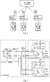
Fig. 1 is a schematic diagram of a parallel converter system including four converters; -
Fig. 2 is a flow diagram of a control method for the parallel converter system; -
Fig. 3 is a structural view of a control system for the parallel converter system; -
Fig. 4 is a block diagram illustrating the control function of a parallel converter system including two converters. - The technical solution of the invention is expounded below in combination with the accompanying drawings and embodiments.
-
Fig. 1 shows a schematic diagram of a parallel converter system including four converters. The parallel converter system comprises four parallel converters, namely a converter C1, a converter C2, a converter C3, and a converter C4, wherein the converter C1 is connected to an AC bus B1 through a converter transformer T1 and an incoming switch Q1, the converter C2 is connected to the AC bus B1 through a converter transformer T2 and an incoming switch Q2, the converter C3 is connected to an AC bus B2 through a converter transformer T3 and an incoming switch Q3, and the converter C4 is connected to the AC bus B2 through a converter transformer T4 and an incoming switch Q4; the AC bus B1 is connected to the AC bus B2 through a bus-bar switch QM; and the AC bus B1 and the AC bus B2 are both connected to an island AC system including a new-energy power generation system. -
Fig. 2 shows a flow diagram of a control method for the parallel converter system. To keep the AC voltage amplitude and frequency of the island AC systems stable, the AC bus to which the parallel connectors are connected is controlled through the following steps: - 101: A system voltage phase reference value θref is calculated according to a frequency reference value Fref. In a preferred implementation, θref ( t ) =θref ( t-Δt )+2πFrefΔt, wherein θref ( t ) is a system voltage phase reference value at the current moment, and θref ( t-Δt ) is a system voltage phase reference value before interval control by a Δt cycle and is set as 0 initially; and Fref is valued in two approaches which are respectively as follows:
- (i) Fref is a rated system frequency Fn such as 50HZ; and
- (ii) Fref meets Fref = Fn + Kf (Pref-P), wherein Kf is a proportionality coefficient, which is appropriately selected from -100 to 100 according to an actual system, Pref is a total active power reference value of the parallel converters, and P is actual total active power of the parallel converters.
- 102: A bus voltage across the AC bus is acquired. In a preferred implementation, a three-phase bus voltage across the AC bus is acquired and is subject to park transformation according to the system voltage phase reference value eref to obtain a bus voltage d-axis component Usd and a bus voltage q-axis component Usq.
- 103: The acquired bus voltage is processed to obtain an active current reference value Idref and a wattless current reference value Iqref In a preferred implementation, a deviation between the bus voltage d-axis component Usd and an effective bus voltage reference value is modulated by a PI controller to generate the active current reference value Idrefi a deviation between the bus voltage q-axis component Usq and 0 is modulated by a PI controller to generate the wattless current reference value Iqref , so that the active current reference value Idref and the wattless current reference value Iqref are actually exclusively determined by the effective bus voltage reference value and the system voltage phase reference value θref determining d-axis and q-axis angles.
- 104: The active current reference value Idrefi the wattless current reference value Iqref , and the system voltage phase reference value θref , served as a converter control signal, are outputted to each converter in island control mode. When a power distribution function is required to distribute power of a plurality of converters, for converters having the output power required to be reduced, the active current reference value Idref is multiplied by a power distribution coefficient less than 1. For instance, when the active power of the ith converter in the island control mode is expected to be 0.5 of that of other converters and wattles power of the ith converter in the island control mode is expected to be 0.6 of that of other converters, the active current reference value Idref sent to the ith converter in the island control mode is multiplied by an active power distribution coefficient Kdi =0.5 to obtain an active current reference value Idrefi of the ith converter in the island control mode, and the wattless current reference value Iqref is multiplied by a wattless power distribution coefficient Kqi =0.6 to obtain a wattless current reference value Iqrefi of the ith converter in the island control mode; and the active power distribution coefficient and the wattless power distribution coefficient of other converters are 1. Particularly, when the active power distribution coefficient and the wattless power distribution coefficient of all the converters in the island control modes are 1, the power of the converters is balanced in operation.
- 105: According to the received control signal, an active current of any converter in the island control mode is controlled to follow the active current reference value Idrefi and a wattless current of any converter in the island control mode is controlled to follow the wattless current reference value Iqref When the active power of any converter in the island control modes needs to be limited, the active current reference value is limited to be less than or equal to an active current limit value Idlim, that is, the active current reference value is in the range of [-Idlim, Idlim ]; and when the wattless power of any converter in the island control modes needs to be limited, the wattless current reference value is limited to be less than or equal to a wattless current limit value Iqlim , that is, the wattless current reference value is in the range of [-Iqlim, Iqlim ]. The active current limit value Idlim is generated through the following solution:
- The active current limit value Idlim is generated by modulating a deviation between an active power limit value such as the maximum overloading active power and actual active power of the converters through a PI controller;
- The wattless current limit value Iqlim is generated through the following solution:
The wattless current limit value Iqlim is generated by modulating a deviation between a wattless power limit value such as the maximum wattless power limited by a power range and actual wattless power of the converters through a PI controller. - In the case where converters which do not adopt the island control modes and the converters which adopt the island control modes are connected in parallel to the same bus, active power control or DC voltage control is adopted for active control, and wattless power control is adopted for wattless control.
-
Fig. 3 shows a structural view of a control system for a parallel converter system. The control system comprises a common AC voltage controller and current controllers 1-N, wherein N is the number of converters in island control modes in the parallel converter system; the current controller i is a controller of the ith converter in the island control mode, i is selected from 1 to N, and the current controllers are independent of one another. The AC voltage controller and any current controller are configured in different control devices, and a control signal, including an active current reference value Idrefi a wattless current reference value Iqref , and a system voltage phase reference value θref , of the ith converter is sent to the current controller i of the corresponding converter by means of communication through a standard protocol. The AC voltage controller and the current controllers can be configured in the same control device. Or a plurality of AC voltage controllers are configured in a plurality of control devices, and if this is the case, a switching logic should be set to guarantee that the current controllers of all the converters merely adopt the converter control signal outputted by one of the AC voltage controllers at a same time according to a preset priority. -
Fig. 4 shows a block diagram illustrating the control function of a parallel converter system including two converters. An AC voltage controller comprises a reference phase generation stage, an AC voltage sampling stage, a current reference value calculating stage, and a power distribution stage, wherein in the reference phase generating stage, a system voltage phase reference value θref is calculated according to a frequency reference value Fref; in the AC voltage sampling stage, and a three-phase bus voltage across the AC bus is acquired and is subject to park transformation according to the system voltage phase reference value θref to obtain a bus voltage d-axis component Usd and a bus voltage q-axis component Usq; in the current reference value calculating stage, a deviation between the bus voltage d-axis component Usd and an effective bus voltage reference value is modulated by a PI controller to generate an active current reference value Idref, a deviation between the bus voltage q-axis component Usq and 0 is modulated by a PI controller to generate a wattless current reference value Iqref , and a sliding mode controller, a dead-beat controller, or a non-linear controller may be adopted; in the power distribution stage, with regard to the 1st converter in the island control mode, the active current reference value Idref is multiplied by an active power distribution coefficient Kdl to obtain an active current reference value Idrefl, and the wattless current reference value Iqref is multiplied by a wattless power distribution coefficient Kql to obtain a wattless current reference value Iqrefl ; with regard to the 2nd converter in the island control mode, the active current reference value Idref is multiplied by an active power distribution coefficient Kd2 to obtain an active current reference value Idref2, and the wattless current reference value Iqref is multiplied by a wattless power distribution coefficient Kq2 to obtain a wattless current reference value Iqref2, wherein, 0≤Kdl ≤1, 0≤Kql ≤1, 0≤Kd2 ≤1, and 0≤Kq2 ≤1, and when the two converters operate symmetrically, Kdl = Kql = Kd2 = Kq2 =1; and in this case, it is equivalent to no configuration of the power distribution stage. Corresponding current controllers, namely acurrent controller 1 and acurrent controller 2, are configured for the two converters, and the power limitation stage is configured for the two current controllers. With regard to the ith converter (i= 1 or 2), an active current limit value Idlim, is generated by modulating a deviation between the maximum overloading active power Plimi and actual active power Psi through a PI controller, and a wattless current limit value Iqlimi is generated by modulating a deviation between the maximum wattless power Qlimi and actual wattless power Qsi through a PI controller; and an active current reference value Idrefi is defined as a boundary value when out of the range of [-Idlimi, Idlimi ], and a wattless current reference value Iqrefi is defined as a boundary value when out of the range of [-Iqlimi, Iqlimi ]. Vector control is adopted for inner loop current control of the converters, and the ith converter is controlled according to active and wattless current instructions outputted in the power limitation stage and the system voltage phase reference value θref - The above embodiments are only used for explaining the technical idea of the invention, and are not intended to limit the protection scope of the invention.
Claims (8)
- A control method for a parallel converter system, the parallel converter system comprising at least two parallel voltage source converters connected in parallel to a same AC bus or to connected AC buses, at least one of the converters operating in an island control mode, and the control method comprising the following steps:(1) calculating a system voltage phase reference value θref according to a frequency reference value Fref (101);(2) acquiring a bus voltage across the AC bus(102);(3) processing the acquired bus voltage to obtain an active current reference value Idref and a wattless current reference value Iqref which are determined by an effective bus voltage reference value and the system voltage phase reference value θref (103);(4) outputting the active current reference value Idref, the wattless current reference value Iqref, and the system voltage phase reference value θref, served as a converter control signal, to each converter in said island control mode(104); and(5) controlling an active current of any converter in the island control mode to follow the active current reference value Idref and controlling a wattless current of any converter in the island control mode to follow the wattless current reference value Iqref according to the received control signal(105);wherein the converter in the island control mode aims to control an amplitude and frequency of the voltage of the AC bus;characterized in that when active power of any converter needs to be limited, the active current reference value is limited to be less than or equal to an active current limit value Idlim; and when wattless power of any converter needs to be limited, the wattless current reference value is limited to be less than or equal to a wattless current limit value Iqlim ;the active current limit value Idlim is generated through the following solution:
the active current limit value Idlim is generated by modulating a deviation between an active power limit value and actual active power of the converter through a PI controller;the wattless current limit value Iqlim is generated through the following solution:
the wattless current limit value Iqlim is generated by modulating a deviation between a wattless power limit value and actual wattless power of the converter through a PI controller. - The control method for a parallel converter system according to Claim 1, wherein the frequency reference value Fref is a rated system frequency Fn or meets Fref = Fn + Kf(Pref- P), where Kf is a proportionality coefficient ranging from -100 to 100, Pref is a total active power reference value of the parallel converters, and P is actual total active power of the parallel converters.
- The control method for a parallel converter system according to Claim 1, wherein before the converter control signal is outputted to an ith converter in the island control mode in Step (4), the active current reference value Idref is multiplied by an active power distribution coefficient Kdi to obtain an active current reference value Idrefi of the ith converter in the island control mode, and the wattless current reference value Iqref is multiplied by a wattless power distribution coefficient Kqi to obtain a wattless current reference value Iqref , of the ith converter in the island control mode, where 0≤Kdi ≤1, 0≤Kqi≤1, i ranges from 1 to a number of the converters in the island control mode, and the active power distribution coefficients Kd or the wattless power distribution coefficients Kq of the converters are identical or different from each other.
- The control method for a parallel converter system according to Claim 1, wherein current vector control is adopted for any converter in the island control mode in Step (5).
- A control system for a parallel converter system, the parallel converter system comprising at least two parallel voltage source converters connected in parallel to a same AC bus or to connected AC buses, the control system comprising a common AC voltage controller and a current controller having separate converters, and the AC voltage controller conducting the following stages:a reference phase generating stage: a system voltage phase reference value θref is calculated according to a frequency reference value Fref;an AC voltage sampling stage: a bus voltage across the AC bus is acquired;a current reference value calculating stage: the acquired bus voltage is processed to obtain an active current reference value Idref and a wattless current reference value Iqref which are exclusively determined by an effective bus voltage reference value and the system voltage phase reference value θref; wherein:the AC voltage controller outputs the active current reference value Idref, the wattless current reference value Iqref, and the system voltage phase reference value θref; searved as a converter control signal, to the current controller of each converter in said island control mode by means of communication, to make an active current outputted by each converter to follow the active current reference value Idref and make a wattless current outputted by each converter to follow the wattless current reference value Iqref,the AC voltage controller is configured through one of the following two solutions:(i) the AC voltage controller and the current controllers of the converters are configured in a same control device;(ii) the AC voltage controller and the current controllers of the converters are configured in different control devices; andwhen AC voltage controllers are configured in a plurality of control devices, the current controllers of all the converters adopt the converter control signal outputted by only one of the AC voltage controllers at a same time according to a preset priority;characterized in that the current controller of said converter comprises a power limitation stage: the active current reference value is limited to be less than or equal to an active current limit value Idlim, and the wattless current reference value is limited to be less than or equal to a wattless current limit value Iqlim ;the active current limit value Idlim is generated through the following solution:
the active current limit value Idlim is generated by modulating a deviation between an active power limit value and actual active power of the converter through a PI controller;the wattless current limit value Iqlim is generated through the following solution:
the wattless current limit value Iqlim is generated by modulating a deviation between a wattless power limit value and actual wattless power of the converter through a PI controller. - The control system for a parallel converter system according to Claim 5, wherein the AC voltage controller is a proportional-integral controller, a sliding mode controller, a dead-beat controller, or a non-linear controller, and the current controllers are selected from proportional-integral controllers, sliding mode controllers, dead-beat controllers, or non-linear controllers.
- The control system for a parallel converter system according to Claim 5, wherein the AC voltage controller further comprises a power distribution stage: for an ith converter in the island control mode, the active current reference value Idref is multiplied by an active power distribution coefficient Kdi to obtain an active current reference value Idrefi of the ith converter in the island control mode, and the wattless current reference value Iqref is multiplied by a wattless power distribution coefficient Kqi to obtain a wattless current reference value Iqref , of the ith converter in the island control mode, where 0≤Kdi ≤1, 0≤Kqi ≤1, i ranges from 1 to a number of the converters in the island control mode, and the active power distribution coefficients Kd or the wattless power distribution coefficients Kq of the converters are identical or different from each other.
- The control system for a parallel converter system according to Claim 5, wherein when the AC voltage controller and the current controllers are configured in a same control device, a reference signal is transmitted via a backplane bus; and when the AC voltage controller and the current controllers are configured in different devices, communication is by means of a standard protocol which is an IEC60044-8 protocol, an Ethernet protocol, or a TDM protocol.
Applications Claiming Priority (2)
| Application Number | Priority Date | Filing Date | Title |
|---|---|---|---|
| CN201710788447.3A CN107565589B (en) | 2017-09-05 | 2017-09-05 | Control system and control method of parallel converter system |
| PCT/CN2018/087796 WO2019047559A1 (en) | 2017-09-05 | 2018-05-22 | Control system and control method for parallel converter system |
Publications (3)
| Publication Number | Publication Date |
|---|---|
| EP3664245A1 EP3664245A1 (en) | 2020-06-10 |
| EP3664245A4 EP3664245A4 (en) | 2020-06-24 |
| EP3664245B1 true EP3664245B1 (en) | 2022-07-06 |
Family
ID=60979217
Family Applications (1)
| Application Number | Title | Priority Date | Filing Date |
|---|---|---|---|
| EP18854241.9A Active EP3664245B1 (en) | 2017-09-05 | 2018-05-22 | Control system and control method for parallel converter system |
Country Status (10)
| Country | Link |
|---|---|
| US (1) | US11355932B2 (en) |
| EP (1) | EP3664245B1 (en) |
| JP (1) | JP6903821B2 (en) |
| KR (1) | KR102345372B1 (en) |
| CN (1) | CN107565589B (en) |
| CA (1) | CA3074761A1 (en) |
| DK (1) | DK3664245T3 (en) |
| MX (1) | MX2020002439A (en) |
| RU (1) | RU2740938C9 (en) |
| WO (1) | WO2019047559A1 (en) |
Families Citing this family (12)
| Publication number | Priority date | Publication date | Assignee | Title |
|---|---|---|---|---|
| CN107565589B (en) * | 2017-09-05 | 2022-05-17 | 南京南瑞继保电气有限公司 | Control system and control method of parallel converter system |
| DE102019210793A1 (en) * | 2019-07-22 | 2021-01-28 | Robert Bosch Gmbh | Electrical energy storage system and method for its operation |
| CN111463818B (en) * | 2020-04-09 | 2022-07-22 | 南京南瑞继保电气有限公司 | Parallel converter system controller and control method |
| CN112054682B (en) * | 2020-09-22 | 2022-06-14 | 曲阜师范大学 | Current sharing control method for flexible direct-current transmission direct-current converter of offshore wind farm |
| CN112505473B (en) * | 2020-10-21 | 2022-02-01 | 北京交通大学 | Analytic calculation method for bipolar short-circuit fault transient current of flexible direct-current power grid |
| CN113193583B (en) * | 2021-04-19 | 2022-07-05 | 中国电建集团华东勘测设计研究院有限公司 | Sending-end MMC sliding mode variable structure control method for offshore wind field flexible and straight system |
| CN114362265A (en) * | 2021-12-07 | 2022-04-15 | 燕山大学 | Reactive power flexible control method for series-parallel electric energy router |
| CN115425698B (en) * | 2022-08-23 | 2023-10-20 | 广东电网有限责任公司广州供电局 | Reactive power distribution method and reactive power distribution system under hybrid control of flexible direct current transmission |
| CN115940256B (en) * | 2022-11-22 | 2023-08-04 | 中国人民解放军陆军工程大学 | Island detection transition process control method of PET (polyethylene terephthalate), electronic equipment and storage medium |
| CN115800332B (en) * | 2023-01-09 | 2023-05-23 | 西安领充创享新能源科技有限公司 | Load adjusting method and system |
| CN117117946B (en) * | 2023-09-22 | 2024-02-09 | 燕山大学 | Freedom degree parameter design method for series-parallel architecture electric energy router |
| CN117293855B (en) * | 2023-11-24 | 2024-02-13 | 湖南大学 | Novel energy station with adjustable inertia and grid connection method |
Family Cites Families (15)
| Publication number | Priority date | Publication date | Assignee | Title |
|---|---|---|---|---|
| JPS61224831A (en) | 1985-03-29 | 1986-10-06 | 株式会社東芝 | Controller for dc power transmission system |
| IL125328A0 (en) * | 1998-07-13 | 1999-03-12 | Univ Ben Gurion | Modular apparatus for regulating the harmonics of current drawn from power lines |
| JP2001025171A (en) | 1999-07-07 | 2001-01-26 | Toshiba Corp | Controller and phase detection circuit for self-excited ac-dc converter |
| JP3762240B2 (en) * | 2001-03-13 | 2006-04-05 | 東芝三菱電機産業システム株式会社 | Control device for self-excited inverter |
| EP1770850A1 (en) * | 2005-10-03 | 2007-04-04 | ABB Schweiz AG | Systems of parallel operating power electronic converters |
| US7660135B2 (en) * | 2007-05-23 | 2010-02-09 | Hamilton Sundstrand Corporation | Universal AC high power inveter with galvanic isolation for linear and non-linear loads |
| US9425622B2 (en) * | 2013-01-08 | 2016-08-23 | Infineon Technologies Austria Ag | Power converter circuit with AC output and at least one transformer |
| DE102012003309B4 (en) | 2012-02-18 | 2022-10-20 | Volkswagen Aktiengesellschaft | Electrical power system in a motor vehicle and method for operating a power system |
| RU2490777C1 (en) | 2012-04-03 | 2013-08-20 | Владимир Яковлевич Грошев | Direct current converter |
| US20150015072A1 (en) * | 2013-07-12 | 2015-01-15 | Infineon Technologies Austria Ag | Power Converter Circuit and Method |
| CN104426157B (en) * | 2013-09-10 | 2017-04-19 | 台达电子企业管理(上海)有限公司 | Energy storage module and energy storage device |
| CN103730908B (en) * | 2013-10-30 | 2017-01-18 | 国家电网公司 | Method for controlling energy storage converters in large-scale off-grid micro-grid |
| CN103904676B (en) * | 2014-03-27 | 2016-01-20 | 浙江大学 | The droop control method of a kind of VSC-HVDC |
| WO2017004125A1 (en) * | 2015-07-02 | 2017-01-05 | Dynapower Company Llc | Islanding a plurality of grid tied power converters |
| CN107565589B (en) * | 2017-09-05 | 2022-05-17 | 南京南瑞继保电气有限公司 | Control system and control method of parallel converter system |
-
2017
- 2017-09-05 CN CN201710788447.3A patent/CN107565589B/en active Active
-
2018
- 2018-05-22 RU RU2020111496A patent/RU2740938C9/en active
- 2018-05-22 MX MX2020002439A patent/MX2020002439A/en unknown
- 2018-05-22 EP EP18854241.9A patent/EP3664245B1/en active Active
- 2018-05-22 WO PCT/CN2018/087796 patent/WO2019047559A1/en unknown
- 2018-05-22 US US16/644,225 patent/US11355932B2/en active Active
- 2018-05-22 KR KR1020207006872A patent/KR102345372B1/en active IP Right Grant
- 2018-05-22 DK DK18854241.9T patent/DK3664245T3/en active
- 2018-05-22 JP JP2020513649A patent/JP6903821B2/en active Active
- 2018-05-22 CA CA3074761A patent/CA3074761A1/en not_active Abandoned
Also Published As
| Publication number | Publication date |
|---|---|
| US20200212674A1 (en) | 2020-07-02 |
| RU2740938C9 (en) | 2021-05-28 |
| US11355932B2 (en) | 2022-06-07 |
| CN107565589B (en) | 2022-05-17 |
| WO2019047559A1 (en) | 2019-03-14 |
| JP6903821B2 (en) | 2021-07-14 |
| DK3664245T3 (en) | 2022-08-22 |
| KR20200037372A (en) | 2020-04-08 |
| RU2740938C1 (en) | 2021-01-21 |
| KR102345372B1 (en) | 2021-12-29 |
| MX2020002439A (en) | 2020-10-05 |
| EP3664245A4 (en) | 2020-06-24 |
| CA3074761A1 (en) | 2019-03-14 |
| CN107565589A (en) | 2018-01-09 |
| EP3664245A1 (en) | 2020-06-10 |
| JP2020532944A (en) | 2020-11-12 |
Similar Documents
| Publication | Publication Date | Title |
|---|---|---|
| EP3664245B1 (en) | Control system and control method for parallel converter system | |
| Pinto et al. | A novel distributed direct-voltage control strategy for grid integration of offshore wind energy systems through MTDC network | |
| Vandoorn et al. | Transition from islanded to grid-connected mode of microgrids with voltage-based droop control | |
| CN110690731A (en) | Power electronic transformer applicable to hybrid micro-grid and coordination control and mode switching method thereof | |
| Raza et al. | Intra-and inter-phase power management and control of a residential microgrid at the distribution level | |
| Jin et al. | Coordination secondary control for autonomous hybrid AC/DC microgrids with global power sharing operation | |
| Rodrigues et al. | Integration of solid state transformer with DC microgrid system | |
| Choi et al. | Selective frequency synchronization technique for fast grid connection of islanded microgrid using prediction method | |
| Zhao et al. | Distributed power quality enhancement using residential power routers | |
| Vandoorn et al. | Voltage control in islanded microgrids by means of a linear-quadratic regulator | |
| Costabeber et al. | Surround control of distributed energy resources in micro-grids | |
| Callegari et al. | Voltage support and selective harmonic current compensation in advanced ac microgrids | |
| Majji et al. | MPC‐based DC microgrid integrated series active power filter for voltage quality improvement in distribution system | |
| Hamrouni et al. | Control approach of a connected PV system under grid faults | |
| Josep et al. | Hierarchical control of power plants with microgrid operation | |
| Pota et al. | Islanded operation of microgrids with inverter connected renewable energy resources | |
| Mastromauro et al. | Hierarchical control of a small wind turbine system for active integration in LV distribution network | |
| Pham et al. | Application of energy routers for frequency support in an AC/DC multi-microgrid system | |
| Pilehvar et al. | Interconnection of three single-phase feeders in North America distribution systems | |
| Ashabani | Synchronous converter and synchronous-VSC-state of art of universal control strategies for smart grid integration | |
| WO2017030804A1 (en) | Method for independent real and reactive power flow control using locally available parameters | |
| Gaiceanu et al. | Power electronic converters in AC microgrid | |
| Ahmed et al. | A state of the art review of control techniques for power electronics converter based distributed generation systems in different modes of operation | |
| Burgos–Mellado et al. | Consensus-Based Distributed Control for Improving the Sharing of Unbalanced Currents in Three-Phase Three-Wire Isolated Microgrids | |
| Ionescu | Voltage control design for grid connected photovoltaic systems |
Legal Events
| Date | Code | Title | Description |
|---|---|---|---|
| STAA | Information on the status of an ep patent application or granted ep patent |
Free format text: STATUS: THE INTERNATIONAL PUBLICATION HAS BEEN MADE |
|
| PUAI | Public reference made under article 153(3) epc to a published international application that has entered the european phase |
Free format text: ORIGINAL CODE: 0009012 |
|
| STAA | Information on the status of an ep patent application or granted ep patent |
Free format text: STATUS: REQUEST FOR EXAMINATION WAS MADE |
|
| 17P | Request for examination filed |
Effective date: 20200302 |
|
| AK | Designated contracting states |
Kind code of ref document: A1 Designated state(s): AL AT BE BG CH CY CZ DE DK EE ES FI FR GB GR HR HU IE IS IT LI LT LU LV MC MK MT NL NO PL PT RO RS SE SI SK SM TR |
|
| AX | Request for extension of the european patent |
Extension state: BA ME |
|
| A4 | Supplementary search report drawn up and despatched |
Effective date: 20200527 |
|
| RIC1 | Information provided on ipc code assigned before grant |
Ipc: H02J 3/46 20060101ALI20200519BHEP Ipc: H02J 3/36 20060101AFI20200519BHEP Ipc: H02J 3/50 20060101ALI20200519BHEP Ipc: H02J 3/12 20060101ALI20200519BHEP Ipc: H02J 3/38 20060101ALI20200519BHEP Ipc: H02J 3/48 20060101ALI20200519BHEP |
|
| DAV | Request for validation of the european patent (deleted) | ||
| DAX | Request for extension of the european patent (deleted) | ||
| STAA | Information on the status of an ep patent application or granted ep patent |
Free format text: STATUS: EXAMINATION IS IN PROGRESS |
|
| 17Q | First examination report despatched |
Effective date: 20210630 |
|
| GRAP | Despatch of communication of intention to grant a patent |
Free format text: ORIGINAL CODE: EPIDOSNIGR1 |
|
| STAA | Information on the status of an ep patent application or granted ep patent |
Free format text: STATUS: GRANT OF PATENT IS INTENDED |
|
| INTG | Intention to grant announced |
Effective date: 20220411 |
|
| GRAS | Grant fee paid |
Free format text: ORIGINAL CODE: EPIDOSNIGR3 |
|
| GRAA | (expected) grant |
Free format text: ORIGINAL CODE: 0009210 |
|
| STAA | Information on the status of an ep patent application or granted ep patent |
Free format text: STATUS: THE PATENT HAS BEEN GRANTED |
|
| AK | Designated contracting states |
Kind code of ref document: B1 Designated state(s): AL AT BE BG CH CY CZ DE DK EE ES FI FR GB GR HR HU IE IS IT LI LT LU LV MC MK MT NL NO PL PT RO RS SE SI SK SM TR |
|
| REG | Reference to a national code |
Ref country code: AT Ref legal event code: REF Ref document number: 1503569 Country of ref document: AT Kind code of ref document: T Effective date: 20220715 Ref country code: CH Ref legal event code: EP |
|
| REG | Reference to a national code |
Ref country code: DE Ref legal event code: R096 Ref document number: 602018037737 Country of ref document: DE |
|
| REG | Reference to a national code |
Ref country code: IE Ref legal event code: FG4D |
|
| REG | Reference to a national code |
Ref country code: DK Ref legal event code: T3 Effective date: 20220818 |
|
| REG | Reference to a national code |
Ref country code: LT Ref legal event code: MG9D |
|
| REG | Reference to a national code |
Ref country code: NL Ref legal event code: MP Effective date: 20220706 |
|
| PG25 | Lapsed in a contracting state [announced via postgrant information from national office to epo] |
Ref country code: SE Free format text: LAPSE BECAUSE OF FAILURE TO SUBMIT A TRANSLATION OF THE DESCRIPTION OR TO PAY THE FEE WITHIN THE PRESCRIBED TIME-LIMIT Effective date: 20220706 Ref country code: RS Free format text: LAPSE BECAUSE OF FAILURE TO SUBMIT A TRANSLATION OF THE DESCRIPTION OR TO PAY THE FEE WITHIN THE PRESCRIBED TIME-LIMIT Effective date: 20220706 Ref country code: PT Free format text: LAPSE BECAUSE OF FAILURE TO SUBMIT A TRANSLATION OF THE DESCRIPTION OR TO PAY THE FEE WITHIN THE PRESCRIBED TIME-LIMIT Effective date: 20221107 Ref country code: NO Free format text: LAPSE BECAUSE OF FAILURE TO SUBMIT A TRANSLATION OF THE DESCRIPTION OR TO PAY THE FEE WITHIN THE PRESCRIBED TIME-LIMIT Effective date: 20221006 Ref country code: NL Free format text: LAPSE BECAUSE OF FAILURE TO SUBMIT A TRANSLATION OF THE DESCRIPTION OR TO PAY THE FEE WITHIN THE PRESCRIBED TIME-LIMIT Effective date: 20220706 Ref country code: LV Free format text: LAPSE BECAUSE OF FAILURE TO SUBMIT A TRANSLATION OF THE DESCRIPTION OR TO PAY THE FEE WITHIN THE PRESCRIBED TIME-LIMIT Effective date: 20220706 Ref country code: LT Free format text: LAPSE BECAUSE OF FAILURE TO SUBMIT A TRANSLATION OF THE DESCRIPTION OR TO PAY THE FEE WITHIN THE PRESCRIBED TIME-LIMIT Effective date: 20220706 Ref country code: FI Free format text: LAPSE BECAUSE OF FAILURE TO SUBMIT A TRANSLATION OF THE DESCRIPTION OR TO PAY THE FEE WITHIN THE PRESCRIBED TIME-LIMIT Effective date: 20220706 Ref country code: ES Free format text: LAPSE BECAUSE OF FAILURE TO SUBMIT A TRANSLATION OF THE DESCRIPTION OR TO PAY THE FEE WITHIN THE PRESCRIBED TIME-LIMIT Effective date: 20220706 |
|
| REG | Reference to a national code |
Ref country code: AT Ref legal event code: MK05 Ref document number: 1503569 Country of ref document: AT Kind code of ref document: T Effective date: 20220706 |
|
| PG25 | Lapsed in a contracting state [announced via postgrant information from national office to epo] |
Ref country code: PL Free format text: LAPSE BECAUSE OF FAILURE TO SUBMIT A TRANSLATION OF THE DESCRIPTION OR TO PAY THE FEE WITHIN THE PRESCRIBED TIME-LIMIT Effective date: 20220706 Ref country code: IS Free format text: LAPSE BECAUSE OF FAILURE TO SUBMIT A TRANSLATION OF THE DESCRIPTION OR TO PAY THE FEE WITHIN THE PRESCRIBED TIME-LIMIT Effective date: 20221106 Ref country code: HR Free format text: LAPSE BECAUSE OF FAILURE TO SUBMIT A TRANSLATION OF THE DESCRIPTION OR TO PAY THE FEE WITHIN THE PRESCRIBED TIME-LIMIT Effective date: 20220706 Ref country code: GR Free format text: LAPSE BECAUSE OF FAILURE TO SUBMIT A TRANSLATION OF THE DESCRIPTION OR TO PAY THE FEE WITHIN THE PRESCRIBED TIME-LIMIT Effective date: 20221007 |
|
| REG | Reference to a national code |
Ref country code: DE Ref legal event code: R097 Ref document number: 602018037737 Country of ref document: DE |
|
| PG25 | Lapsed in a contracting state [announced via postgrant information from national office to epo] |
Ref country code: SM Free format text: LAPSE BECAUSE OF FAILURE TO SUBMIT A TRANSLATION OF THE DESCRIPTION OR TO PAY THE FEE WITHIN THE PRESCRIBED TIME-LIMIT Effective date: 20220706 Ref country code: RO Free format text: LAPSE BECAUSE OF FAILURE TO SUBMIT A TRANSLATION OF THE DESCRIPTION OR TO PAY THE FEE WITHIN THE PRESCRIBED TIME-LIMIT Effective date: 20220706 Ref country code: CZ Free format text: LAPSE BECAUSE OF FAILURE TO SUBMIT A TRANSLATION OF THE DESCRIPTION OR TO PAY THE FEE WITHIN THE PRESCRIBED TIME-LIMIT Effective date: 20220706 Ref country code: AT Free format text: LAPSE BECAUSE OF FAILURE TO SUBMIT A TRANSLATION OF THE DESCRIPTION OR TO PAY THE FEE WITHIN THE PRESCRIBED TIME-LIMIT Effective date: 20220706 |
|
| PLBE | No opposition filed within time limit |
Free format text: ORIGINAL CODE: 0009261 |
|
| STAA | Information on the status of an ep patent application or granted ep patent |
Free format text: STATUS: NO OPPOSITION FILED WITHIN TIME LIMIT |
|
| PG25 | Lapsed in a contracting state [announced via postgrant information from national office to epo] |
Ref country code: SK Free format text: LAPSE BECAUSE OF FAILURE TO SUBMIT A TRANSLATION OF THE DESCRIPTION OR TO PAY THE FEE WITHIN THE PRESCRIBED TIME-LIMIT Effective date: 20220706 Ref country code: EE Free format text: LAPSE BECAUSE OF FAILURE TO SUBMIT A TRANSLATION OF THE DESCRIPTION OR TO PAY THE FEE WITHIN THE PRESCRIBED TIME-LIMIT Effective date: 20220706 |
|
| 26N | No opposition filed |
Effective date: 20230411 |
|
| PG25 | Lapsed in a contracting state [announced via postgrant information from national office to epo] |
Ref country code: AL Free format text: LAPSE BECAUSE OF FAILURE TO SUBMIT A TRANSLATION OF THE DESCRIPTION OR TO PAY THE FEE WITHIN THE PRESCRIBED TIME-LIMIT Effective date: 20220706 |
|
| PGFP | Annual fee paid to national office [announced via postgrant information from national office to epo] |
Ref country code: FR Payment date: 20230523 Year of fee payment: 6 Ref country code: DK Payment date: 20230523 Year of fee payment: 6 Ref country code: DE Payment date: 20230525 Year of fee payment: 6 |
|
| PG25 | Lapsed in a contracting state [announced via postgrant information from national office to epo] |
Ref country code: SI Free format text: LAPSE BECAUSE OF FAILURE TO SUBMIT A TRANSLATION OF THE DESCRIPTION OR TO PAY THE FEE WITHIN THE PRESCRIBED TIME-LIMIT Effective date: 20220706 |
|
| PGFP | Annual fee paid to national office [announced via postgrant information from national office to epo] |
Ref country code: GB Payment date: 20230526 Year of fee payment: 6 |
|
| REG | Reference to a national code |
Ref country code: CH Ref legal event code: PL |
|
| PG25 | Lapsed in a contracting state [announced via postgrant information from national office to epo] |
Ref country code: MC Free format text: LAPSE BECAUSE OF FAILURE TO SUBMIT A TRANSLATION OF THE DESCRIPTION OR TO PAY THE FEE WITHIN THE PRESCRIBED TIME-LIMIT Effective date: 20220706 |
|
| REG | Reference to a national code |
Ref country code: BE Ref legal event code: MM Effective date: 20230531 |
|
| PG25 | Lapsed in a contracting state [announced via postgrant information from national office to epo] |
Ref country code: MC Free format text: LAPSE BECAUSE OF FAILURE TO SUBMIT A TRANSLATION OF THE DESCRIPTION OR TO PAY THE FEE WITHIN THE PRESCRIBED TIME-LIMIT Effective date: 20220706 Ref country code: LU Free format text: LAPSE BECAUSE OF NON-PAYMENT OF DUE FEES Effective date: 20230522 Ref country code: LI Free format text: LAPSE BECAUSE OF NON-PAYMENT OF DUE FEES Effective date: 20230531 Ref country code: IT Free format text: LAPSE BECAUSE OF FAILURE TO SUBMIT A TRANSLATION OF THE DESCRIPTION OR TO PAY THE FEE WITHIN THE PRESCRIBED TIME-LIMIT Effective date: 20220706 Ref country code: CH Free format text: LAPSE BECAUSE OF NON-PAYMENT OF DUE FEES Effective date: 20230531 |
|
| REG | Reference to a national code |
Ref country code: IE Ref legal event code: MM4A |
|
| PG25 | Lapsed in a contracting state [announced via postgrant information from national office to epo] |
Ref country code: IE Free format text: LAPSE BECAUSE OF NON-PAYMENT OF DUE FEES Effective date: 20230522 |
|
| PG25 | Lapsed in a contracting state [announced via postgrant information from national office to epo] |
Ref country code: IE Free format text: LAPSE BECAUSE OF NON-PAYMENT OF DUE FEES Effective date: 20230522 |