EP3664201A1 - Fuel battery cell - Google Patents
Fuel battery cell Download PDFInfo
- Publication number
- EP3664201A1 EP3664201A1 EP17920196.7A EP17920196A EP3664201A1 EP 3664201 A1 EP3664201 A1 EP 3664201A1 EP 17920196 A EP17920196 A EP 17920196A EP 3664201 A1 EP3664201 A1 EP 3664201A1
- Authority
- EP
- European Patent Office
- Prior art keywords
- support plate
- electrode layer
- main body
- battery cell
- anode electrode
- Prior art date
- Legal status (The legal status is an assumption and is not a legal conclusion. Google has not performed a legal analysis and makes no representation as to the accuracy of the status listed.)
- Granted
Links
Images


Classifications
-
- H—ELECTRICITY
- H01—ELECTRIC ELEMENTS
- H01M—PROCESSES OR MEANS, e.g. BATTERIES, FOR THE DIRECT CONVERSION OF CHEMICAL ENERGY INTO ELECTRICAL ENERGY
- H01M4/00—Electrodes
- H01M4/86—Inert electrodes with catalytic activity, e.g. for fuel cells
- H01M4/8605—Porous electrodes
- H01M4/8621—Porous electrodes containing only metallic or ceramic material, e.g. made by sintering or sputtering
-
- H—ELECTRICITY
- H01—ELECTRIC ELEMENTS
- H01M—PROCESSES OR MEANS, e.g. BATTERIES, FOR THE DIRECT CONVERSION OF CHEMICAL ENERGY INTO ELECTRICAL ENERGY
- H01M8/00—Fuel cells; Manufacture thereof
- H01M8/02—Details
- H01M8/0202—Collectors; Separators, e.g. bipolar separators; Interconnectors
- H01M8/0204—Non-porous and characterised by the material
- H01M8/0206—Metals or alloys
-
- H—ELECTRICITY
- H01—ELECTRIC ELEMENTS
- H01M—PROCESSES OR MEANS, e.g. BATTERIES, FOR THE DIRECT CONVERSION OF CHEMICAL ENERGY INTO ELECTRICAL ENERGY
- H01M8/00—Fuel cells; Manufacture thereof
- H01M8/02—Details
- H01M8/0202—Collectors; Separators, e.g. bipolar separators; Interconnectors
- H01M8/0247—Collectors; Separators, e.g. bipolar separators; Interconnectors characterised by the form
-
- H—ELECTRICITY
- H01—ELECTRIC ELEMENTS
- H01M—PROCESSES OR MEANS, e.g. BATTERIES, FOR THE DIRECT CONVERSION OF CHEMICAL ENERGY INTO ELECTRICAL ENERGY
- H01M8/00—Fuel cells; Manufacture thereof
- H01M8/02—Details
- H01M8/0271—Sealing or supporting means around electrodes, matrices or membranes
- H01M8/0273—Sealing or supporting means around electrodes, matrices or membranes with sealing or supporting means in the form of a frame
-
- H—ELECTRICITY
- H01—ELECTRIC ELEMENTS
- H01M—PROCESSES OR MEANS, e.g. BATTERIES, FOR THE DIRECT CONVERSION OF CHEMICAL ENERGY INTO ELECTRICAL ENERGY
- H01M8/00—Fuel cells; Manufacture thereof
- H01M8/10—Fuel cells with solid electrolytes
- H01M8/12—Fuel cells with solid electrolytes operating at high temperature, e.g. with stabilised ZrO2 electrolyte
- H01M8/1213—Fuel cells with solid electrolytes operating at high temperature, e.g. with stabilised ZrO2 electrolyte characterised by the electrode/electrolyte combination or the supporting material
-
- Y—GENERAL TAGGING OF NEW TECHNOLOGICAL DEVELOPMENTS; GENERAL TAGGING OF CROSS-SECTIONAL TECHNOLOGIES SPANNING OVER SEVERAL SECTIONS OF THE IPC; TECHNICAL SUBJECTS COVERED BY FORMER USPC CROSS-REFERENCE ART COLLECTIONS [XRACs] AND DIGESTS
- Y02—TECHNOLOGIES OR APPLICATIONS FOR MITIGATION OR ADAPTATION AGAINST CLIMATE CHANGE
- Y02E—REDUCTION OF GREENHOUSE GAS [GHG] EMISSIONS, RELATED TO ENERGY GENERATION, TRANSMISSION OR DISTRIBUTION
- Y02E60/00—Enabling technologies; Technologies with a potential or indirect contribution to GHG emissions mitigation
- Y02E60/30—Hydrogen technology
- Y02E60/50—Fuel cells
Definitions
- the present invention relates to a fuel battery cell including a battery structure with a lamination of an anode electrode layer, an electrolyte layer, and a cathode electrode layer, and a support plate that is made of metal and that supports the battery structure.
- Patent Document 1 As a conventional fuel battery cell, one described in Patent Document 1 is known.
- the fuel battery cell disclosed in Patent Document 1 includes a plate (a support plate), which is produced by powder metallurgy.
- the plate has a porous base plate region and an air-tight end region. This plate is formed integrally with the air-tight end region by compressing an end part of a sintered flat porous body using a press die.
- a battery layer having electrochemical activity is attached to the porous base plate region on a flat surface of the plate, that is, on a surface in which the porous base plate region and the end region continue on the same plane.
- the fuel battery has a structure, in which an air-tight electrolyte layer constituting the battery layer extends to the end region, thereby securing a gas barrier property at an end part of the battery layer.
- Such a fuel battery is typically manufactured by successively forming battery structures, each of the battery structure being formed by successively laminating an anode electrode layer, an electrolyte layer, and a cathode electrode layer on the plate.
- Patent Document 1 JP 2010-534901T
- the support plate which has the air-tight end region integrated with an outer periphery of the porous base plate region, has a structure-changed region due to changes in thickness, changes in void fraction (porosity), and changes in strength, and heat history during a manufacturing process, and the like, between the porous base plate region and the end region. Therefore, a conventional fuel battery cell has a risk of application of an excessive load that can cause a crack and the like in the electrolyte layer at the time the support plate expands or contracts in accordance with power generation or stoppage (heat generation or cooling). For this reason, an improvement is necessary to enhance a gas barrier property at an end part of the battery structure.
- An object of the present invention is to provide a fuel battery cell in which a risk of application of a tensile load to an electrolyte layer is removed, in particular when a support plate contracts after power generation is stopped, whereby occurrence of a crack and the like in the electrolyte layer are prevented beforehand, and a good gas barrier property at an end part of a battery structure is maintained.
- the fuel battery cell according to the present invention includes a battery structure and a support plate that is made of metal.
- the battery structure has a power generation region of a lamination of an anode electrode layer, an electrolyte layer, and a cathode electrode layer.
- the support plate made of metal is disposed on the anode electrode layer side of the battery structure to support the battery structure.
- the support plate integrally includes a main body part at a center and a frame part at an outer periphery of the main body part.
- the main body part has gas permeability and is in contact with the power generation region of the anode electrode layer.
- the frame part has gas impermeability and has a smaller thickness than a thickness of the main body part.
- the support plate has a step surface between the main body part and the frame part, on a surface on the anode electrode layer side.
- the electrolyte layer of the battery structure is disposed in a way it extends to an outer periphery side of the power generation region and reaches the step surface and the frame part.
- the fuel battery cell according to the present invention thermally expands as a whole during power generation.
- the support plate contracts after the power generation is stopped, the support plate, which has the step surface on the surface on the anode electrode layer side, is displaced to curve in a way that the step surface is on the inner side of the curve, because contraction amounts on the both surface sides differ from each other due to difference in the surface areas. Therefore, a compressive load occurs on the step surface side, and a tensile load occurs on the opposite surface in the fuel battery cell.
- the battery structure is disposed on the step surface side of the support plate while the electrolyte layer is disposed in a way it extends to the step surface and the frame part having gas impermeability, whereby a tensile load is not applied to the electrolyte layer. Therefore, a gas barrier property is secured between the electrolyte layer and the frame part.
- a fuel battery cell FC illustrated in FIG. 1 is, for example, a solid oxide fuel battery, and includes a battery structure 1, a support plate 2 that is made of metal and that supports the battery structure 1, and a pair of separators 3, 3 that form a gas channel between the battery structure 1 and the support plate 2.
- This fuel battery cell FC may be referred to as a "metal-supported cell", because mechanical strength is increased while gas permeability is secured by the support plate 2.
- the battery structure 1 has a lamination of an anode electrode layer (fuel electrode layer) 4, an electrolyte layer 5 comprising solid electrolyte, and a cathode electrode layer (air electrode layer) 6 in this order, from a lower side in the figure.
- the region in which the three layers 4 to 6 overlap on one another is a power generation region G having electrochemical activity.
- the anode electrode layer 4 uses a cermet of nickel and yttria-stabilized zirconia
- the electrolyte layer 5 uses 8 mol% yttria-stabilized zirconia
- the cathode electrode layer 6 uses lanthanum strontium manganite.
- the support plate 2 made of metal may be disposed on either of the electrode layers 4 and 6 sides, when it is disposed in order to reinforce strength of the battery structure 1. However, the support plate 2 is disposed on the anode electrode layer 4 side of the battery structure 1 to prevent oxidation.
- the support plate 2 integrally includes a main body part 2A at a center and a frame part 2B at an outer periphery of the main body part 2B.
- the main body part 2A has gas permeability and is in contact with the power generation region G of the anode electrode layer 4.
- the frame part 2B has gas impermeability and has relatively a small thickness Tb with respect to the thickness Ta of the main body part 2A.
- the support plate 2 has a step surface 2D between the main body part 2A and the frame part 2B on a surface on the anode electrode layer 4 side.
- the support plate 2 of this embodiment includes an intermediate part 2C that continuously connects the main body part 2A and the frame part 2B.
- the thickness of the intermediate part 2C continuously decreases from the main body part 2A to the frame part 2B. Due to this, the step surface 2D of the support plate 2 is inclined from the main body part 2A to the frame part 2B.
- the support plate 2 is made of a porous metal material, such as foamed metal, By applying pressure to a peripheral part of the porous metal material, for example, by press working, a porous composition still remains in a center part, and it serves as the main body part 2A having gas permeability.
- the pressurized peripheral part having a dense composition serves as the frame part 2B having gas impermeability.
- the support plate 2 integrally includes the main body part 2A and the thinned frame part 2B.
- the support plate 2 of this embodiment has the intermediate part 2C and the step surface 2D on one surface side.
- the opposite surface is a flat surface, in which the main body part 2A, the intermediate part 2C, and the frame part 2B continue on the same plane.
- the electrolyte layer 5 of the battery structure 1 is disposed in a way it extends to an outer periphery side of the power generation region G and reach the step surface 2D and the frame part 2B.
- the extended part of the electrolyte layer 5 is referred to as an "outer peripheral edge part 5A".
- the anode electrode layer 4 of the battery structure 1 has an outer peripheral edge part 4A that is disposed in a way it extends to the outer periphery side of the power generation region G along the step surface 2D and the frame part 2B.
- the outer peripheral edge part 5A of the electrolyte layer 5 covers the outer peripheral edge part 4A of the anode electrode layer 4 and also covers a peripheral end surface 4E of the outer peripheral edge part 4A of the anode electrode layer 4 in the frame part 2B.
- the thickness of the anode electrode layer 4 is set such that a thermal expansion amount of the anode electrode layer 4 is equivalent to the thermal expansion amount of the intermediate part 2C of the support plate 2, and the thicknesses of the anode electrode layer 4 at the power generation region G and at the outer peripheral edge part 4A are the same.
- the thickness of the anode electrode layer 4, by which the anode electrode layer 4 has the thermal expansion amount equivalent to the thermal expansion amount of the intermediate part 2C is a thickness that provides a displacement amount equivalent to the displacement amount (deformation amount) of the intermediate part at the time the support plate 2 thermally expands.
- the cathode electrode layer 6 of the battery structure 1 is provided to the support plate 2 in a range of the main body part 2A and is provided only in the range of the main body part 2A in the example illustrated in the figure. Due to this, the fuel battery cell FC has the power generation region G, which comprises the three layers 4 to 6 of the battery structure 1, within the range of the main body part 2A of the support plate 2 and has the outer peripheral edge parts 4A and 5A of the anode electrode layer 4 and the electrolyte layer 5 disposed along the step surface 2D and the frame part 2B.
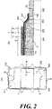
- the support plate 2 having the battery structure 1, and the pair of the separators 3, 3 have rectangular shapes with approximately the same longitudinal and lateral dimensions, as illustrated in FIG. 1 .
- a gas channel for circulating cathode gas (air) is formed between one separator 3 and the cathode electrode layer 6 of the battery structure 1 and a gas channel for circulating anode gas (fuel gas) is formed between the other separator 3 and the anode electrode layer 4 / the support plate 2.
- the fuel battery cell FC includes a manifold hole H1 for supplying the anode gas and a manifold hole H2 for discharging the cathode gas that are formed on one short side of the support plate 2 and the pair of the separators 3, 3.
- a manifold hole H3 for discharging the anode gas and a manifold hole H4 for supplying the cathode gas are formed on the other short side.
- manifold holes H1 to H4 communicate with each other to form manifolds for circulating the respective gases when the battery structure 1 and the separators 3 are laminated to assemble a fuel battery cell stack.
- the battery structures 1 adjacent in the stacking direction share one separator 3 between them.
- a sealing member S is provided between outer peripheral parts of the support plate 2 and each of the separators 3 and around the manifold holes H1 to H4, thereby air-tightness of the gas channels is secured.
- the sealing member S is not disposed around the manifold holes H1 to H4 or an open part is provided in a part of the sealing member S, in order to allow the gas corresponding to the respective gas channel to circulate.
- the fuel battery cell FC generates electrical energy due to electrochemical reaction in the power generation region G, by supplying the anode gas to the anode electrode layer 4 of the battery structure 1 and also supplying the cathode gas to the cathode electrode layer 6. At this time, the anode gas is supplied to the anode electrode layer 4 through the main body part 2A having gas permeability in the support plate 2.
- the support plate 2 illustrated in FIG. 3A includes the main body part 2A, the frame part 2B, the intermediate part 2C, and the inclined step surface 2D that are integrally formed by applying pressure to a part of a porous metal material, as described above.
- the support plate 2 has an opposite surface with no step surface 2D, which is a flat surface on which the main body part 2A, the frame part 2B, and the intermediate part 2C continue on the same plane.
- a material for an anode electrode is applied on an upper surface of the main body part 2A, the step surface 2D, and the frame part 2B, on the surface of the support plate 2 where the step surface 2D is formed, and the anode electrode layer 4 is formed by burning this.
- the support plate 2 is heated with the periphery restricted by a jig (not illustrated).
- an electrolyte layer 5 is formed on an upper surface of the anode electrode layer 4 by sputtering, to cover the anode electrode layer 4 to its peripheral end surface 4E.
- a material for a cathode electrode is applied on an upper surface in the power generation region G of the electrolyte layer 5, and the cathode electrode layer 6 is formed by burning this.
- the support plate 2 is heated with the periphery restricted by a jig in a similar manner as described above. Then, the support plate 2 is cooled and contracts accordingly, whereby the internal stress is reset.
- the support plate 2 has a large structural change at the intermediate part 2C having the step surface 2D, due to changes in thickness, changes in void fraction (porosity), changes in strength, and heat history during the manufacturing process, and the like. Therefore, the support plate 2 generates heat and thermally expands as a whole during power generation. However, a difference in contraction amount is generated between the surface on the step surface 2D side and the opposite side surface (flat surface) after power generation is stopped.
- the support plate 2 has a greater contraction amount on the step surface 2D side than that on the opposite side surface, because the surface area on the step surface 2D side is greater than that of the opposite side surface by the amount of the step surface 2D.
- the support plate 2 is displaced (deformed) to curve in a way that the step surface 2D of the intermediate part 2C is on the inner side of the curve, as indicated by a bold arrow in FIG. 3D , in accordance with cooling after power generation is stopped.
- the electrolyte layer 5 has a relatively low resistance against a tensile load and has a relatively high resistance against a compressive load.
- the battery structure 1 is disposed on the step surface 2D side of the support plate 2 and the electrolyte layer 5 is disposed in a way it extends to the step surface 2D and the frame part 2B having gas impermeability. Therefore, although the compressive load A1 generated in the intermediate part 2C of the support plate 2 is applied to the electrolyte layer 5, the tensile load A2 is not applied thereto.
- a gas barrier property is secured at an end part of the battery structure 1 between the electrolyte layer 5 (outer peripheral edge part 5A) and the frame part 2B.
- the anode electrode layer 4 also thermally expands in addition to the support plate 2.
- the support plate 2 has an asymmetric shape relative to a center line of the thickness and has a volume of the half part having the step surface 2D smaller than the volume of the other half part.
- the support plate 2 is slightly deformed in a way that the step surface 2D is on the inner side of the deformation, and a compressive load is generated in the intermediate part 2C.
- the support plate 2 is made of a porous metal material, and the frame part 2B is formed by applying pressure to a part of the porous metal material in the thickness direction, to have a dense structure. Due to this, in the fuel battery cell FC, the support plate 2 that integrally has the main body part 2A with gas permeability and the frame part 2B with gas impermeability by using a single material. Thus, it is suitable for mass production.
- the thickness of the intermediate part 2C of the support plate 2 continuously reduces in the range from the main body part 2A to the frame part 2B, and the step surface 2D is inclined. Therefore, in the fuel battery cell FC, the structural change in the intermediate part 2C is moderated, and concentration of thermal stress is suppressed.
- the anode electrode layer 4 of the battery structure 1 has the outer peripheral edge part 4A, which is disposed along the step surface 2D and the frame part 2B, as with the electrolyte layer 5, and the peripheral end surface 4E of the outer peripheral edge part 4A of the anode electrode layer 4 is covered with the outer peripheral edge part 5A of the electrolyte layer 5 at the frame part 2B. Therefore, in the fuel battery cell FC, as described above, a force generated by thermal expansion of the anode electrode layer 4 acts in a direction of canceling the force generated in the intermediate part 2C, thereby the displacement amount of the support plate 2 can be suppressed and the gas barrier property at the end part of the battery structure 1 can be sufficiently secured.
- the thickness of the anode electrode layer 4 is set such that a thermal expansion amount of the anode electrode layer 4 is equivalent to the thermal expansion amount of the intermediate part 2C of the support plate 2. Therefore, a thermal expansion force of the anode electrode layer 4 and a compressive load of the intermediate part 2C act in a way they cancel each other, thereby displacement of the support plate 2 is suppressed. That is, in the fuel battery cell FC, while a compressive load is applied to the electrolyte layer 5, thermal expansion of the anode electrode layer 4 suppresses displacement of the support plate 2, thereby application of an excessive compressive load to the electrolyte layer 5 is prevented.
- the thicknesses of the anode electrode layer 4 is set to be the same in the power generation region G and in the outer peripheral edge part 4A. Therefore, application of an excessive compressive load to the electrolyte layer 5 is prevented, and also concentration of thermal stress due to rapid shape change in the anode electrode layer 4 is prevented.
- the cathode electrode layer 6 of the battery structure 1 is provided to the support plate 2 in the range of the main body part 2A. That is, in the fuel battery cell FC, the cathode electrode layer 6 having a large thermal expansion rate is provided only in the power generation region G of the battery structure 1, thereby preventing displacement of the cathode electrode layer 6 due to thermal expansion from affecting the intermediate part 2C (step surface 2D). Thus, a load to be applied to the end part of the battery structure 1 is reduced.
- FIGs. 4 to 7 illustrate second to fourth embodiments of the fuel battery cell of the present invention.
- the same constitutional parts as those of the first embodiment are denoted by the same reference signs, and detailed descriptions thereof are omitted.
- the fuel battery cell FC illustrated in FIG. 4 has step surfaces 2D, 2D formed by the change of the thickness of the intermediate part 2C, on both surfaces of the support plate 2. That is, the support plate 2 of this embodiment has a symmetric shape with respect to the center line of the thickness.
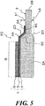
- the fuel battery cell FC illustrated in FIG. 5 has step surfaces 2D, 2D on both surfaces of the support plate 2.
- a step size h2 between the main body part 2A and the frame part 2B on the opposite surface side is smaller than a step size h1 between the main body part 2A and the frame part 2B on the surface where the battery structure 1 is disposed.
- the support plate 2 of this embodiment has an asymmetric shape with respect to the center line of the thickness, and although both of the step surfaces 2D, 2D are inclined, the area of the step surface 2D on the surface where the battery structure 1 is disposed is greater than the area of the step surface 2D on the opposite side, due to the difference between the step sizes h1 and h2.
- both of the contraction displacement of the support plate 2 after power generation is stopped and the thermal expansion of the support plate 2 and the anode electrode layer 4 are taken into consideration. That is, when the support plate 2 contracts after power generation is stopped, a contraction amount on the step surface 2D side having the large step size h1 is greater than the contraction amount on the step surface 2D side having the small step size h2, due to the difference in the surface areas.
- the support plate 2 is displaced to curve in a way that the step surface 2D with the large step size h1 is on the inner side of the curve, whereby a compressive load is applied to the inner inside of the curve, while a tensile load is applied to the outer side of the curve.
- the fuel battery cell FC illustrated in FIG. 6 differs from the fuel battery cell FC in the first embodiment (refer to FIG. 2 ) in that only the electrolyte layer 5 has the outer peripheral edge part 5A and is disposed in a way it extends to the frame part 2B, whereas the anode electrode layer 4 and the electrolyte layer 5 respectively have the outer peripheral edge parts 4A, 5A in the first embodiment.
- the fuel battery cell FC illustrated in FIG. 7 does not have the intermediate part 2C, whereas in the foregoing embodiments the support plate 2 has the intermediate part 2C and the step surface 2D. That is, the support plate 2 has a step surface 2D orthogonal in an in-plane direction between the main body part 2A and the frame part 2B that is thinner than the main body part 2A. Although the step surface 2D illustrated in the figure is orthogonal in the in-plane direction, the step surface 2D may have a slight inclination and may have a round corner.
- the support plate 2 contracts after power generation is stopped, the support plate 2 is deformed to curve in a way that the step surface 2D is on the inner side of the curve, because the surface area on the step surface 2D side is greater than that of the opposite side surface by the amount of the step surface 2D.
- the battery structure 1 is disposed on the step surface 2D side, and therefore a risk of application of a tensile load to the electrolyte layer 5 is removed, when the support plate 2 contracts after power generation is stopped, whereby occurrence of a crack and the like in the electrolyte layer 5 are prevented beforehand.
- a good gas barrier property at the end part of the battery structure 1 is maintained.
- the configuration of the fuel battery cell according to the present invention is not limited only to those in the foregoing embodiments but can be modified or changed appropriately within the gist of the present invention, or the configurations of each of the foregoing embodiments can be combined.
Landscapes
- Chemical & Material Sciences (AREA)
- Engineering & Computer Science (AREA)
- Chemical Kinetics & Catalysis (AREA)
- Electrochemistry (AREA)
- General Chemical & Material Sciences (AREA)
- Life Sciences & Earth Sciences (AREA)
- Manufacturing & Machinery (AREA)
- Sustainable Development (AREA)
- Sustainable Energy (AREA)
- Ceramic Engineering (AREA)
- Fuel Cell (AREA)
Abstract
Description
- The present invention relates to a fuel battery cell including a battery structure with a lamination of an anode electrode layer, an electrolyte layer, and a cathode electrode layer, and a support plate that is made of metal and that supports the battery structure.
- As a conventional fuel battery cell, one described in
Patent Document 1 is known. The fuel battery cell disclosed inPatent Document 1 includes a plate (a support plate), which is produced by powder metallurgy. The plate has a porous base plate region and an air-tight end region. This plate is formed integrally with the air-tight end region by compressing an end part of a sintered flat porous body using a press die. - In the fuel battery, a battery layer having electrochemical activity is attached to the porous base plate region on a flat surface of the plate, that is, on a surface in which the porous base plate region and the end region continue on the same plane. The fuel battery has a structure, in which an air-tight electrolyte layer constituting the battery layer extends to the end region, thereby securing a gas barrier property at an end part of the battery layer. Such a fuel battery is typically manufactured by successively forming battery structures, each of the battery structure being formed by successively laminating an anode electrode layer, an electrolyte layer, and a cathode electrode layer on the plate.
- Patent Document 1:
JP 2010-534901T - In a fuel battery cell as described above, the support plate (plate), which has the air-tight end region integrated with an outer periphery of the porous base plate region, has a structure-changed region due to changes in thickness, changes in void fraction (porosity), and changes in strength, and heat history during a manufacturing process, and the like, between the porous base plate region and the end region. Therefore, a conventional fuel battery cell has a risk of application of an excessive load that can cause a crack and the like in the electrolyte layer at the time the support plate expands or contracts in accordance with power generation or stoppage (heat generation or cooling). For this reason, an improvement is necessary to enhance a gas barrier property at an end part of the battery structure.
- The present invention has been made to solve the above-described problem by focusing on the lower resistance of the electrolyte layer against a tensile load than a compressive load. An object of the present invention is to provide a fuel battery cell in which a risk of application of a tensile load to an electrolyte layer is removed, in particular when a support plate contracts after power generation is stopped, whereby occurrence of a crack and the like in the electrolyte layer are prevented beforehand, and a good gas barrier property at an end part of a battery structure is maintained.
- The fuel battery cell according to the present invention includes a battery structure and a support plate that is made of metal. The battery structure has a power generation region of a lamination of an anode electrode layer, an electrolyte layer, and a cathode electrode layer. The support plate made of metal is disposed on the anode electrode layer side of the battery structure to support the battery structure. The support plate integrally includes a main body part at a center and a frame part at an outer periphery of the main body part. The main body part has gas permeability and is in contact with the power generation region of the anode electrode layer. The frame part has gas impermeability and has a smaller thickness than a thickness of the main body part. The support plate has a step surface between the main body part and the frame part, on a surface on the anode electrode layer side. In the fuel battery cell, the electrolyte layer of the battery structure is disposed in a way it extends to an outer periphery side of the power generation region and reaches the step surface and the frame part.
- The fuel battery cell according to the present invention thermally expands as a whole during power generation. However, when the support plate contracts after the power generation is stopped, the support plate, which has the step surface on the surface on the anode electrode layer side, is displaced to curve in a way that the step surface is on the inner side of the curve, because contraction amounts on the both surface sides differ from each other due to difference in the surface areas. Therefore, a compressive load occurs on the step surface side, and a tensile load occurs on the opposite surface in the fuel battery cell. In these conditions, in the fuel battery cell, the battery structure is disposed on the step surface side of the support plate while the electrolyte layer is disposed in a way it extends to the step surface and the frame part having gas impermeability, whereby a tensile load is not applied to the electrolyte layer. Therefore, a gas barrier property is secured between the electrolyte layer and the frame part.
- Thus, in the fuel battery cell, a risk of application of a tensile load to the electrolyte layer is removed, when the support plate contracts after power generation is stopped, whereby occurrence of a crack and the like in the electrolyte layer are prevented beforehand, and a good gas barrier property at the end part of the battery structure can be maintained.
-
-
FIG. 1 is an exploded perspective view of a fuel battery cell for illustrating a first embodiment of the present invention. -
FIG. 2A is a plane view of the fuel battery cell, andFIG. 2B is a sectional view taken along line A-A inFIG. 2A . -
FIGs. 3A to 3D are sectional views for illustrating a manufacturing process of the fuel battery cell. -
FIG. 4 is a sectional view of a main body part for illustrating a second embodiment of the fuel battery cell of the present invention. -
FIG. 5 is a sectional view of a main body part for illustrating a third embodiment of the fuel battery cell of the present invention. -
FIG. 6 is a sectional view of a main body part for illustrating a fourth embodiment of the fuel battery cell of the present invention. -
FIG. 7 is a sectional view of a main body part for illustrating a fifth embodiment of the fuel battery cell of the present invention. - A fuel battery cell FC illustrated in
FIG. 1 is, for example, a solid oxide fuel battery, and includes abattery structure 1, asupport plate 2 that is made of metal and that supports thebattery structure 1, and a pair ofseparators battery structure 1 and thesupport plate 2. This fuel battery cell FC may be referred to as a "metal-supported cell", because mechanical strength is increased while gas permeability is secured by thesupport plate 2. - As illustrated in
FIG. 2 , thebattery structure 1 has a lamination of an anode electrode layer (fuel electrode layer) 4, anelectrolyte layer 5 comprising solid electrolyte, and a cathode electrode layer (air electrode layer) 6 in this order, from a lower side in the figure. The region in which the threelayers 4 to 6 overlap on one another is a power generation region G having electrochemical activity. - In a solid oxide fuel battery cell, for example, the
anode electrode layer 4 uses a cermet of nickel and yttria-stabilized zirconia, theelectrolyte layer 5 uses 8 mol% yttria-stabilized zirconia, and thecathode electrode layer 6 uses lanthanum strontium manganite. - The
support plate 2 made of metal may be disposed on either of theelectrode layers battery structure 1. However, thesupport plate 2 is disposed on theanode electrode layer 4 side of thebattery structure 1 to prevent oxidation. Thesupport plate 2 integrally includes amain body part 2A at a center and aframe part 2B at an outer periphery of themain body part 2B. Themain body part 2A has gas permeability and is in contact with the power generation region G of theanode electrode layer 4. Theframe part 2B has gas impermeability and has relatively a small thickness Tb with respect to the thickness Ta of themain body part 2A. Thesupport plate 2 has astep surface 2D between themain body part 2A and theframe part 2B on a surface on theanode electrode layer 4 side. - The
support plate 2 of this embodiment includes anintermediate part 2C that continuously connects themain body part 2A and theframe part 2B. The thickness of theintermediate part 2C continuously decreases from themain body part 2A to theframe part 2B. Due to this, thestep surface 2D of thesupport plate 2 is inclined from themain body part 2A to theframe part 2B. - The
support plate 2 is made of a porous metal material, such as foamed metal, By applying pressure to a peripheral part of the porous metal material, for example, by press working, a porous composition still remains in a center part, and it serves as themain body part 2A having gas permeability. In thesupport plate 2, the pressurized peripheral part having a dense composition serves as theframe part 2B having gas impermeability. Thus, thesupport plate 2 integrally includes themain body part 2A and thethinned frame part 2B. Moreover, thesupport plate 2 of this embodiment has theintermediate part 2C and thestep surface 2D on one surface side. The opposite surface is a flat surface, in which themain body part 2A, theintermediate part 2C, and theframe part 2B continue on the same plane. - In this fuel battery cell FC, the
electrolyte layer 5 of thebattery structure 1 is disposed in a way it extends to an outer periphery side of the power generation region G and reach thestep surface 2D and theframe part 2B. The extended part of theelectrolyte layer 5 is referred to as an "outerperipheral edge part 5A". - In this embodiment, as with the
electrolyte layer 5, theanode electrode layer 4 of thebattery structure 1 has an outerperipheral edge part 4A that is disposed in a way it extends to the outer periphery side of the power generation region G along thestep surface 2D and theframe part 2B. In the fuel battery cell FC, the outerperipheral edge part 5A of theelectrolyte layer 5 covers the outerperipheral edge part 4A of theanode electrode layer 4 and also covers aperipheral end surface 4E of the outerperipheral edge part 4A of theanode electrode layer 4 in theframe part 2B. - Moreover, in the fuel battery cell FC, the thickness of the
anode electrode layer 4 is set such that a thermal expansion amount of theanode electrode layer 4 is equivalent to the thermal expansion amount of theintermediate part 2C of thesupport plate 2, and the thicknesses of theanode electrode layer 4 at the power generation region G and at the outerperipheral edge part 4A are the same. In other words, the thickness of theanode electrode layer 4, by which theanode electrode layer 4 has the thermal expansion amount equivalent to the thermal expansion amount of theintermediate part 2C, is a thickness that provides a displacement amount equivalent to the displacement amount (deformation amount) of the intermediate part at the time thesupport plate 2 thermally expands. - In the fuel battery cell FC, the
cathode electrode layer 6 of thebattery structure 1 is provided to thesupport plate 2 in a range of themain body part 2A and is provided only in the range of themain body part 2A in the example illustrated in the figure. Due to this, the fuel battery cell FC has the power generation region G, which comprises the threelayers 4 to 6 of thebattery structure 1, within the range of themain body part 2A of thesupport plate 2 and has the outerperipheral edge parts anode electrode layer 4 and theelectrolyte layer 5 disposed along thestep surface 2D and theframe part 2B. - In the fuel battery cell FC having the configuration described above, the
support plate 2 having thebattery structure 1, and the pair of theseparators FIG. 1 . In the fuel battery cell FC, a gas channel for circulating cathode gas (air) is formed between oneseparator 3 and thecathode electrode layer 6 of thebattery structure 1 and a gas channel for circulating anode gas (fuel gas) is formed between theother separator 3 and theanode electrode layer 4 / thesupport plate 2. - The fuel battery cell FC includes a manifold hole H1 for supplying the anode gas and a manifold hole H2 for discharging the cathode gas that are formed on one short side of the
support plate 2 and the pair of theseparators - These manifold holes H1 to H4 communicate with each other to form manifolds for circulating the respective gases when the
battery structure 1 and theseparators 3 are laminated to assemble a fuel battery cell stack. When the fuel battery cell stack is assembled, thebattery structures 1 adjacent in the stacking direction share oneseparator 3 between them. - Moreover, in the fuel battery cell FC, a sealing member S is provided between outer peripheral parts of the
support plate 2 and each of theseparators 3 and around the manifold holes H1 to H4, thereby air-tightness of the gas channels is secured. However, the sealing member S is not disposed around the manifold holes H1 to H4 or an open part is provided in a part of the sealing member S, in order to allow the gas corresponding to the respective gas channel to circulate. - The fuel battery cell FC generates electrical energy due to electrochemical reaction in the power generation region G, by supplying the anode gas to the
anode electrode layer 4 of thebattery structure 1 and also supplying the cathode gas to thecathode electrode layer 6. At this time, the anode gas is supplied to theanode electrode layer 4 through themain body part 2A having gas permeability in thesupport plate 2. - Here, a manufacturing process of this fuel battery cell FC is described based on
FIG. 3 . Thesupport plate 2 illustrated inFIG. 3A includes themain body part 2A, theframe part 2B, theintermediate part 2C, and theinclined step surface 2D that are integrally formed by applying pressure to a part of a porous metal material, as described above. Thesupport plate 2 has an opposite surface with nostep surface 2D, which is a flat surface on which themain body part 2A, theframe part 2B, and theintermediate part 2C continue on the same plane. - Next, as illustrated in
FIG. 3B , a material for an anode electrode is applied on an upper surface of themain body part 2A, thestep surface 2D, and theframe part 2B, on the surface of thesupport plate 2 where thestep surface 2D is formed, and theanode electrode layer 4 is formed by burning this. At this time, thesupport plate 2 is heated with the periphery restricted by a jig (not illustrated). - Subsequently, as illustrated in
FIG. 3C , anelectrolyte layer 5 is formed on an upper surface of theanode electrode layer 4 by sputtering, to cover theanode electrode layer 4 to itsperipheral end surface 4E. Thereafter, a material for a cathode electrode is applied on an upper surface in the power generation region G of theelectrolyte layer 5, and thecathode electrode layer 6 is formed by burning this. At this time, thesupport plate 2 is heated with the periphery restricted by a jig in a similar manner as described above. Then, thesupport plate 2 is cooled and contracts accordingly, whereby the internal stress is reset. - In the fuel battery cell FC that is manufactured through the process described above, the
support plate 2 has a large structural change at theintermediate part 2C having thestep surface 2D, due to changes in thickness, changes in void fraction (porosity), changes in strength, and heat history during the manufacturing process, and the like. Therefore, thesupport plate 2 generates heat and thermally expands as a whole during power generation. However, a difference in contraction amount is generated between the surface on thestep surface 2D side and the opposite side surface (flat surface) after power generation is stopped. - That is, the
support plate 2 has a greater contraction amount on thestep surface 2D side than that on the opposite side surface, because the surface area on thestep surface 2D side is greater than that of the opposite side surface by the amount of thestep surface 2D. As a result, thesupport plate 2 is displaced (deformed) to curve in a way that thestep surface 2D of theintermediate part 2C is on the inner side of the curve, as indicated by a bold arrow inFIG. 3D , in accordance with cooling after power generation is stopped. - This generates a compressive load (arrow A1) on the
step surface 2D side of thesupport plate 2 and generates a tensile load (arrow A2) on the opposite surface, in the fuel battery cell FC. As described above, theelectrolyte layer 5 has a relatively low resistance against a tensile load and has a relatively high resistance against a compressive load. - Meanwhile, in the fuel battery cell FC, the
battery structure 1 is disposed on thestep surface 2D side of thesupport plate 2 and theelectrolyte layer 5 is disposed in a way it extends to thestep surface 2D and theframe part 2B having gas impermeability. Therefore, although the compressive load A1 generated in theintermediate part 2C of thesupport plate 2 is applied to theelectrolyte layer 5, the tensile load A2 is not applied thereto. In addition, in the fuel battery cell FC, a gas barrier property is secured at an end part of thebattery structure 1 between the electrolyte layer 5 (outerperipheral edge part 5A) and theframe part 2B. - When the fuel battery cell FC generates power, the
anode electrode layer 4 also thermally expands in addition to thesupport plate 2. In this state, thesupport plate 2 has an asymmetric shape relative to a center line of the thickness and has a volume of the half part having thestep surface 2D smaller than the volume of the other half part. Thus, when theentire support plate 2 thermally expands, thesupport plate 2 is slightly deformed in a way that thestep surface 2D is on the inner side of the deformation, and a compressive load is generated in theintermediate part 2C. In this situation, in the fuel battery cell FC, because thebattery structure 1 is disposed on thestep surface 2D side of thesupport plate 2, when thermally expanded, a deformation force generated in theanode electrode layer 4 and a deformation force generated in thesupport plate 2 cancel each other. As a result, a displacement amount of thesupport plate 2 is greatly reduced. - Thus, in the fuel battery cell FC, when the
support plate 2 contracts after power generation is stopped, a risk of application of a tensile load to theelectrolyte layer 5 is removed, whereby occurrence of a crack and the like in theelectrolyte layer 5 are prevented beforehand, and a good gas barrier property at the end part of thebattery structure 1 is maintained. - In the fuel battery cell FC, the
support plate 2 is made of a porous metal material, and theframe part 2B is formed by applying pressure to a part of the porous metal material in the thickness direction, to have a dense structure. Due to this, in the fuel battery cell FC, thesupport plate 2 that integrally has themain body part 2A with gas permeability and theframe part 2B with gas impermeability by using a single material. Thus, it is suitable for mass production. - In the fuel battery cell FC, the thickness of the
intermediate part 2C of thesupport plate 2 continuously reduces in the range from themain body part 2A to theframe part 2B, and thestep surface 2D is inclined. Therefore, in the fuel battery cell FC, the structural change in theintermediate part 2C is moderated, and concentration of thermal stress is suppressed. - Moreover, in the fuel battery cell FC, the
anode electrode layer 4 of thebattery structure 1 has the outerperipheral edge part 4A, which is disposed along thestep surface 2D and theframe part 2B, as with theelectrolyte layer 5, and theperipheral end surface 4E of the outerperipheral edge part 4A of theanode electrode layer 4 is covered with the outerperipheral edge part 5A of theelectrolyte layer 5 at theframe part 2B. Therefore, in the fuel battery cell FC, as described above, a force generated by thermal expansion of theanode electrode layer 4 acts in a direction of canceling the force generated in theintermediate part 2C, thereby the displacement amount of thesupport plate 2 can be suppressed and the gas barrier property at the end part of thebattery structure 1 can be sufficiently secured. - Moreover, in the fuel battery cell FC, the thickness of the
anode electrode layer 4 is set such that a thermal expansion amount of theanode electrode layer 4 is equivalent to the thermal expansion amount of theintermediate part 2C of thesupport plate 2. Therefore, a thermal expansion force of theanode electrode layer 4 and a compressive load of theintermediate part 2C act in a way they cancel each other, thereby displacement of thesupport plate 2 is suppressed. That is, in the fuel battery cell FC, while a compressive load is applied to theelectrolyte layer 5, thermal expansion of theanode electrode layer 4 suppresses displacement of thesupport plate 2, thereby application of an excessive compressive load to theelectrolyte layer 5 is prevented. - Furthermore, in the fuel battery cell FC, the thicknesses of the
anode electrode layer 4 is set to be the same in the power generation region G and in the outerperipheral edge part 4A. Therefore, application of an excessive compressive load to theelectrolyte layer 5 is prevented, and also concentration of thermal stress due to rapid shape change in theanode electrode layer 4 is prevented. - In addition, in the fuel battery cell FC, the
cathode electrode layer 6 of thebattery structure 1 is provided to thesupport plate 2 in the range of themain body part 2A. That is, in the fuel battery cell FC, thecathode electrode layer 6 having a large thermal expansion rate is provided only in the power generation region G of thebattery structure 1, thereby preventing displacement of thecathode electrode layer 6 due to thermal expansion from affecting theintermediate part 2C (step surface 2D). Thus, a load to be applied to the end part of thebattery structure 1 is reduced. -
FIGs. 4 to 7 illustrate second to fourth embodiments of the fuel battery cell of the present invention. In the following embodiments, the same constitutional parts as those of the first embodiment are denoted by the same reference signs, and detailed descriptions thereof are omitted. - The fuel battery cell FC illustrated in
FIG. 4 hasstep surfaces intermediate part 2C, on both surfaces of thesupport plate 2. That is, thesupport plate 2 of this embodiment has a symmetric shape with respect to the center line of the thickness. - In this fuel battery cell FC, it is unlikely that the
support plate 2 is displaced in the thickness direction, when thesupport plate 2 thermally expands during power generation or thesupport plate 2 contracts after the power generation is stopped, because thesupport plate 2 has a symmetric shape with respect to the center line of the thickness. Thus, in the fuel battery cell FC, a risk of application of a tensile load to theelectrolyte layer 5 is removed, whereby occurrence of a crack and the like in theelectrolyte layer 5 are prevented beforehand, and a good gas barrier property at the end part of thebattery structure 1 is maintained. - The fuel battery cell FC illustrated in
FIG. 5 hasstep surfaces support plate 2. In this fuel battery cell FC, a step size h2 between themain body part 2A and theframe part 2B on the opposite surface side is smaller than a step size h1 between themain body part 2A and theframe part 2B on the surface where thebattery structure 1 is disposed. - That is, the
support plate 2 of this embodiment has an asymmetric shape with respect to the center line of the thickness, and although both of the step surfaces 2D, 2D are inclined, the area of thestep surface 2D on the surface where thebattery structure 1 is disposed is greater than the area of thestep surface 2D on the opposite side, due to the difference between the step sizes h1 and h2. - In this fuel battery cell FC, both of the contraction displacement of the
support plate 2 after power generation is stopped and the thermal expansion of thesupport plate 2 and theanode electrode layer 4 are taken into consideration. That is, when thesupport plate 2 contracts after power generation is stopped, a contraction amount on thestep surface 2D side having the large step size h1 is greater than the contraction amount on thestep surface 2D side having the small step size h2, due to the difference in the surface areas. Thus, thesupport plate 2 is displaced to curve in a way that thestep surface 2D with the large step size h1 is on the inner side of the curve, whereby a compressive load is applied to the inner inside of the curve, while a tensile load is applied to the outer side of the curve. - In these conditions, in the fuel battery cell FC, because the
battery structure 1 is disposed on thestep surface 2D side having the large step size h1, a tensile load is not applied to theelectrolyte layer 5 when thesupport plate 2 contracts after power generation is stopped. In this fuel battery cell FC, the thermal expansion force of theanode electrode layer 4 and the compressive load generated in theintermediate part 2C are balanced and they act in a way they cancel each other, thereby displacement of thesupport plate 2 is suppressed. Due to this, in the fuel battery cell FC, a risk of application of a tensile load to theelectrolyte layer 5 is removed, whereby occurrence of a crack and the like in theelectrolyte layer 5 are prevented beforehand, and a good gas barrier property at the end part of thebattery structure 1 is maintained. - The fuel battery cell FC illustrated in
FIG. 6 differs from the fuel battery cell FC in the first embodiment (refer toFIG. 2 ) in that only theelectrolyte layer 5 has the outerperipheral edge part 5A and is disposed in a way it extends to theframe part 2B, whereas theanode electrode layer 4 and theelectrolyte layer 5 respectively have the outerperipheral edge parts - Also in this fuel battery cell FC, a risk of application of a tensile load to the
electrolyte layer 5 is removed, when thesupport plate 2 contracts after power generation is stopped, whereby occurrence of a crack and the like in theelectrolyte layer 5 are prevented beforehand, and a good gas barrier property at the end part of thebattery structure 1 is maintained. Further advantage is that it is not necessary to consider thermal expansion of theanode electrode layer 4. - The fuel battery cell FC illustrated in
FIG. 7 does not have theintermediate part 2C, whereas in the foregoing embodiments thesupport plate 2 has theintermediate part 2C and thestep surface 2D. That is, thesupport plate 2 has astep surface 2D orthogonal in an in-plane direction between themain body part 2A and theframe part 2B that is thinner than themain body part 2A. Although thestep surface 2D illustrated in the figure is orthogonal in the in-plane direction, thestep surface 2D may have a slight inclination and may have a round corner. - Also in this fuel battery cell FC, when the
support plate 2 contracts after power generation is stopped, thesupport plate 2 is deformed to curve in a way that thestep surface 2D is on the inner side of the curve, because the surface area on thestep surface 2D side is greater than that of the opposite side surface by the amount of thestep surface 2D. In the fuel battery cell FC, thebattery structure 1 is disposed on thestep surface 2D side, and therefore a risk of application of a tensile load to theelectrolyte layer 5 is removed, when thesupport plate 2 contracts after power generation is stopped, whereby occurrence of a crack and the like in theelectrolyte layer 5 are prevented beforehand. In addition, in this fuel battery cell FC, a good gas barrier property at the end part of thebattery structure 1 is maintained. - The configuration of the fuel battery cell according to the present invention is not limited only to those in the foregoing embodiments but can be modified or changed appropriately within the gist of the present invention, or the configurations of each of the foregoing embodiments can be combined.
-
- FC
- Fuel battery cell
- G
- Power generation region
- h1, h2
- Step size
- Ta
- Thickness of main body part
- Tb
- Thickness of frame part
- 1
- Battery structure
- 2
- Support plate
- 2A
- Main body part
- 2B
- Frame part
- 2C
- Intermediate part
- 2D
- Step surface
- 4
- Anode electrode layer
- 4A
- Outer peripheral edge part of anode electrode layer
- 4E
- Peripheral end surface of anode electrode layer
- 5
- Electrolyte layer
- 5A
- Outer peripheral edge part of electrolyte layer
- 6
- Cathode electrode layer
Claims (7)
- A fuel battery cell comprising a battery structure and a support plate,
the battery structure having a power generation region of a lamination of an anode electrode layer, an electrolyte layer, and a cathode electrode layer, and
the support plate being made of metal and being disposed on the anode electrode layer side of the battery structure to support the battery structure,
wherein
the support plate integrally includes a main body part at a center and a frame part at an outer periphery of the main body part, the main body part having gas permeability and being in contact with the power generation region of the anode electrode layer, the frame part having gas impermeability and having relatively a smaller thickness than a thickness of the main body part,
the support plate has a step surface between the main body part and the frame part, on a surface on the anode electrode layer side, and
the electrolyte layer of the battery structure is disposed in a way it extends to an outer periphery side of the power generation region and reaches the step surface and the frame part. - The fuel battery cell according to claim 1, wherein the support plate has an intermediate part whose thickness continuously reduces from the main body part to the frame part, and the step surface is inclined from the main body part to the frame part.
- The fuel battery cell according to claim 1 or 2, wherein the anode electrode layer of the battery structure includes an outer peripheral edge part that is disposed in a way it extends to the outer periphery side of the power generation region along the step surface and the frame part, and the electrolyte layer covers the outer peripheral edge part of the anode electrode layer, and its peripheral end surface.
- The fuel battery cell according to claim 3, wherein the support plate has an intermediate part whose thickness continuously reduces from the main body part to the frame part, the step surface is inclined from the main body part to the frame part, and the thickness of the anode electrode layer is set such that a thermal expansion amount of the anode electrode layer is equivalent to a thermal expansion amount of the intermediate part.
- The fuel battery cell according to claim 3 or 4, wherein the thicknesses of the anode electrode layer are the same in the power generation region and in the outer peripheral edge part thereof.
- The fuel battery cell according to any one of claims 1 to 5, wherein the cathode electrode layer is provided in a range of the main body part with respect to the support plate.
- The fuel battery cell according to any one of claims 1 to 6, wherein the support plate has the step surface on both surfaces, and a step size between the main body part and the frame part on an opposite surface side to a surface side where the battery structure is disposed, is smaller than a step size between the main body part and the frame part on the surface side where the battery structure is disposed.
Applications Claiming Priority (1)
| Application Number | Priority Date | Filing Date | Title |
|---|---|---|---|
| PCT/JP2017/027733 WO2019026138A1 (en) | 2017-07-31 | 2017-07-31 | Fuel battery cell |
Publications (3)
| Publication Number | Publication Date |
|---|---|
| EP3664201A1 true EP3664201A1 (en) | 2020-06-10 |
| EP3664201A4 EP3664201A4 (en) | 2020-08-19 |
| EP3664201B1 EP3664201B1 (en) | 2020-12-16 |
Family
ID=65232414
Family Applications (1)
| Application Number | Title | Priority Date | Filing Date |
|---|---|---|---|
| EP17920196.7A Active EP3664201B1 (en) | 2017-07-31 | 2017-07-31 | Fuel battery cell |
Country Status (5)
| Country | Link |
|---|---|
| US (1) | US10978714B2 (en) |
| EP (1) | EP3664201B1 (en) |
| JP (1) | JP6856125B2 (en) |
| CN (1) | CN110945698B (en) |
| WO (1) | WO2019026138A1 (en) |
Families Citing this family (3)
| Publication number | Priority date | Publication date | Assignee | Title |
|---|---|---|---|---|
| CN113594486B (en) * | 2021-07-30 | 2025-07-18 | 上海氢晨新能源科技有限公司 | Asymmetric fuel cell polar plate adapting to carbon paper size |
| JP7773408B2 (en) * | 2022-03-14 | 2025-11-19 | 藤倉コンポジット株式会社 | Load Sensor |
| DE112023000206T5 (en) * | 2023-03-24 | 2024-12-19 | Ngk Insulators, Ltd. | electrochemical cell |
Family Cites Families (7)
| Publication number | Priority date | Publication date | Assignee | Title |
|---|---|---|---|---|
| DE10135333A1 (en) * | 2001-07-19 | 2003-02-06 | Elringklinger Ag | fuel cell unit |
| JP4232614B2 (en) * | 2003-11-20 | 2009-03-04 | 日産自動車株式会社 | Solid oxide fuel cell |
| DE102007034967A1 (en) | 2007-07-26 | 2009-01-29 | Plansee Se | Fuel cell and process for its production |
| CN101790810A (en) * | 2007-11-28 | 2010-07-28 | 丰田自动车株式会社 | single cell of fuel cell |
| RU2010147046A (en) | 2008-04-18 | 2012-05-27 | Члены Правления Университета Калифорнии (Us) | COMBINED SEAL FOR HIGH-TEMPERATURE ELECTROCHEMICAL DEVICE |
| DE102013008473A1 (en) * | 2013-05-21 | 2014-11-27 | Plansee Composite Materials Gmbh | FUEL CELL |
| CA2920772C (en) * | 2013-08-08 | 2018-04-17 | Nissan Motor Co., Ltd. | Membrane electrode assembly with frame, fuel cell single cell, and fuel cell stack |
-
2017
- 2017-07-31 US US16/634,676 patent/US10978714B2/en active Active
- 2017-07-31 WO PCT/JP2017/027733 patent/WO2019026138A1/en not_active Ceased
- 2017-07-31 CN CN201780093448.4A patent/CN110945698B/en active Active
- 2017-07-31 EP EP17920196.7A patent/EP3664201B1/en active Active
- 2017-07-31 JP JP2019533745A patent/JP6856125B2/en active Active
Also Published As
| Publication number | Publication date |
|---|---|
| JPWO2019026138A1 (en) | 2020-07-30 |
| JP6856125B2 (en) | 2021-04-07 |
| US10978714B2 (en) | 2021-04-13 |
| EP3664201A4 (en) | 2020-08-19 |
| US20200381740A1 (en) | 2020-12-03 |
| EP3664201B1 (en) | 2020-12-16 |
| CN110945698B (en) | 2020-10-13 |
| WO2019026138A1 (en) | 2019-02-07 |
| CN110945698A (en) | 2020-03-31 |
Similar Documents
| Publication | Publication Date | Title |
|---|---|---|
| KR101870055B1 (en) | Separator-fitted single fuel cell, and fuel cell stack | |
| EP3664201B1 (en) | Fuel battery cell | |
| EP2586088B1 (en) | Fuel cell | |
| KR20210018421A (en) | Solid Oxide Fuel Cell Stack with Reduced Leakage Unit Cells | |
| JP2015088288A (en) | Fuel cell stack | |
| JP6888690B2 (en) | Fuel cell stack | |
| JP6199697B2 (en) | Fuel cell single cell with separator, fuel cell stack, and manufacturing method thereof | |
| US9478812B1 (en) | Interconnect for fuel cell stack | |
| US8383282B2 (en) | Contact arrangement and method for assembling a fuel cell stack from at least one contact arrangement | |
| CN101855768A (en) | High temperature fuel cell stack and its manufacture | |
| CN105594038A (en) | Seal configuration for electrochemical cell | |
| EP3664202B1 (en) | Cell unit | |
| US10411274B2 (en) | Arrangement of electrochemical cells and the use of the same | |
| US11271221B2 (en) | Electrochemical reaction cell stack, interconnector-electrochemical reaction unit cell composite, and method for manufacturing electrochemical reaction cell stack | |
| US20180219244A1 (en) | Fuel cell stack | |
| JP2008034274A (en) | FUEL CELL SEPARATOR, FUEL CELL SEPARATOR CONSTRUCTION PLATE, AND METHOD FOR PRODUCING FUEL CELL SEPARATOR | |
| CN111052474B (en) | Stack structure of fuel cell and thermal strain absorbing method of fuel cell stack | |
| JP5727429B2 (en) | Fuel cell with separator and fuel cell | |
| JP2019186147A (en) | Electrochemical reaction unit and electrochemical reaction cell stack | |
| JP2019009083A (en) | Electrochemical reaction cell and electrochemical reaction cell stack | |
| JP6740856B2 (en) | Fuel cell and method of manufacturing fuel cell |
Legal Events
| Date | Code | Title | Description |
|---|---|---|---|
| STAA | Information on the status of an ep patent application or granted ep patent |
Free format text: STATUS: THE INTERNATIONAL PUBLICATION HAS BEEN MADE |
|
| PUAI | Public reference made under article 153(3) epc to a published international application that has entered the european phase |
Free format text: ORIGINAL CODE: 0009012 |
|
| STAA | Information on the status of an ep patent application or granted ep patent |
Free format text: STATUS: REQUEST FOR EXAMINATION WAS MADE |
|
| 17P | Request for examination filed |
Effective date: 20200226 |
|
| AK | Designated contracting states |
Kind code of ref document: A1 Designated state(s): AL AT BE BG CH CY CZ DE DK EE ES FI FR GB GR HR HU IE IS IT LI LT LU LV MC MK MT NL NO PL PT RO RS SE SI SK SM TR |
|
| AX | Request for extension of the european patent |
Extension state: BA ME |
|
| A4 | Supplementary search report drawn up and despatched |
Effective date: 20200716 |
|
| RIC1 | Information provided on ipc code assigned before grant |
Ipc: H01M 8/12 20160101ALI20200710BHEP Ipc: H01M 8/02 20160101AFI20200710BHEP |
|
| GRAP | Despatch of communication of intention to grant a patent |
Free format text: ORIGINAL CODE: EPIDOSNIGR1 |
|
| STAA | Information on the status of an ep patent application or granted ep patent |
Free format text: STATUS: GRANT OF PATENT IS INTENDED |
|
| RIC1 | Information provided on ipc code assigned before grant |
Ipc: H01M 8/124 20160101ALN20200909BHEP Ipc: H01M 8/0273 20160101ALI20200909BHEP Ipc: H01M 8/12 20160101ALI20200909BHEP Ipc: H01M 8/02 20160101AFI20200909BHEP |
|
| DAV | Request for validation of the european patent (deleted) | ||
| DAX | Request for extension of the european patent (deleted) | ||
| INTG | Intention to grant announced |
Effective date: 20200923 |
|
| GRAS | Grant fee paid |
Free format text: ORIGINAL CODE: EPIDOSNIGR3 |
|
| GRAA | (expected) grant |
Free format text: ORIGINAL CODE: 0009210 |
|
| STAA | Information on the status of an ep patent application or granted ep patent |
Free format text: STATUS: THE PATENT HAS BEEN GRANTED |
|
| AK | Designated contracting states |
Kind code of ref document: B1 Designated state(s): AL AT BE BG CH CY CZ DE DK EE ES FI FR GB GR HR HU IE IS IT LI LT LU LV MC MK MT NL NO PL PT RO RS SE SI SK SM TR |
|
| REG | Reference to a national code |
Ref country code: GB Ref legal event code: FG4D |
|
| REG | Reference to a national code |
Ref country code: DE Ref legal event code: R096 Ref document number: 602017029837 Country of ref document: DE |
|
| REG | Reference to a national code |
Ref country code: IE Ref legal event code: FG4D |
|
| REG | Reference to a national code |
Ref country code: AT Ref legal event code: REF Ref document number: 1346412 Country of ref document: AT Kind code of ref document: T Effective date: 20210115 |
|
| PG25 | Lapsed in a contracting state [announced via postgrant information from national office to epo] |
Ref country code: GR Free format text: LAPSE BECAUSE OF FAILURE TO SUBMIT A TRANSLATION OF THE DESCRIPTION OR TO PAY THE FEE WITHIN THE PRESCRIBED TIME-LIMIT Effective date: 20210317 Ref country code: NO Free format text: LAPSE BECAUSE OF FAILURE TO SUBMIT A TRANSLATION OF THE DESCRIPTION OR TO PAY THE FEE WITHIN THE PRESCRIBED TIME-LIMIT Effective date: 20210316 Ref country code: RS Free format text: LAPSE BECAUSE OF FAILURE TO SUBMIT A TRANSLATION OF THE DESCRIPTION OR TO PAY THE FEE WITHIN THE PRESCRIBED TIME-LIMIT Effective date: 20201216 Ref country code: FI Free format text: LAPSE BECAUSE OF FAILURE TO SUBMIT A TRANSLATION OF THE DESCRIPTION OR TO PAY THE FEE WITHIN THE PRESCRIBED TIME-LIMIT Effective date: 20201216 |
|
| REG | Reference to a national code |
Ref country code: AT Ref legal event code: MK05 Ref document number: 1346412 Country of ref document: AT Kind code of ref document: T Effective date: 20201216 |
|
| REG | Reference to a national code |
Ref country code: NL Ref legal event code: MP Effective date: 20201216 |
|
| PG25 | Lapsed in a contracting state [announced via postgrant information from national office to epo] |
Ref country code: BG Free format text: LAPSE BECAUSE OF FAILURE TO SUBMIT A TRANSLATION OF THE DESCRIPTION OR TO PAY THE FEE WITHIN THE PRESCRIBED TIME-LIMIT Effective date: 20210316 Ref country code: LV Free format text: LAPSE BECAUSE OF FAILURE TO SUBMIT A TRANSLATION OF THE DESCRIPTION OR TO PAY THE FEE WITHIN THE PRESCRIBED TIME-LIMIT Effective date: 20201216 Ref country code: SE Free format text: LAPSE BECAUSE OF FAILURE TO SUBMIT A TRANSLATION OF THE DESCRIPTION OR TO PAY THE FEE WITHIN THE PRESCRIBED TIME-LIMIT Effective date: 20201216 |
|
| PG25 | Lapsed in a contracting state [announced via postgrant information from national office to epo] |
Ref country code: NL Free format text: LAPSE BECAUSE OF FAILURE TO SUBMIT A TRANSLATION OF THE DESCRIPTION OR TO PAY THE FEE WITHIN THE PRESCRIBED TIME-LIMIT Effective date: 20201216 Ref country code: HR Free format text: LAPSE BECAUSE OF FAILURE TO SUBMIT A TRANSLATION OF THE DESCRIPTION OR TO PAY THE FEE WITHIN THE PRESCRIBED TIME-LIMIT Effective date: 20201216 |
|
| REG | Reference to a national code |
Ref country code: LT Ref legal event code: MG9D |
|
| PG25 | Lapsed in a contracting state [announced via postgrant information from national office to epo] |
Ref country code: SK Free format text: LAPSE BECAUSE OF FAILURE TO SUBMIT A TRANSLATION OF THE DESCRIPTION OR TO PAY THE FEE WITHIN THE PRESCRIBED TIME-LIMIT Effective date: 20201216 Ref country code: RO Free format text: LAPSE BECAUSE OF FAILURE TO SUBMIT A TRANSLATION OF THE DESCRIPTION OR TO PAY THE FEE WITHIN THE PRESCRIBED TIME-LIMIT Effective date: 20201216 Ref country code: PT Free format text: LAPSE BECAUSE OF FAILURE TO SUBMIT A TRANSLATION OF THE DESCRIPTION OR TO PAY THE FEE WITHIN THE PRESCRIBED TIME-LIMIT Effective date: 20210416 Ref country code: SM Free format text: LAPSE BECAUSE OF FAILURE TO SUBMIT A TRANSLATION OF THE DESCRIPTION OR TO PAY THE FEE WITHIN THE PRESCRIBED TIME-LIMIT Effective date: 20201216 Ref country code: EE Free format text: LAPSE BECAUSE OF FAILURE TO SUBMIT A TRANSLATION OF THE DESCRIPTION OR TO PAY THE FEE WITHIN THE PRESCRIBED TIME-LIMIT Effective date: 20201216 Ref country code: CZ Free format text: LAPSE BECAUSE OF FAILURE TO SUBMIT A TRANSLATION OF THE DESCRIPTION OR TO PAY THE FEE WITHIN THE PRESCRIBED TIME-LIMIT Effective date: 20201216 Ref country code: LT Free format text: LAPSE BECAUSE OF FAILURE TO SUBMIT A TRANSLATION OF THE DESCRIPTION OR TO PAY THE FEE WITHIN THE PRESCRIBED TIME-LIMIT Effective date: 20201216 |
|
| PG25 | Lapsed in a contracting state [announced via postgrant information from national office to epo] |
Ref country code: PL Free format text: LAPSE BECAUSE OF FAILURE TO SUBMIT A TRANSLATION OF THE DESCRIPTION OR TO PAY THE FEE WITHIN THE PRESCRIBED TIME-LIMIT Effective date: 20201216 Ref country code: AT Free format text: LAPSE BECAUSE OF FAILURE TO SUBMIT A TRANSLATION OF THE DESCRIPTION OR TO PAY THE FEE WITHIN THE PRESCRIBED TIME-LIMIT Effective date: 20201216 |
|
| REG | Reference to a national code |
Ref country code: DE Ref legal event code: R097 Ref document number: 602017029837 Country of ref document: DE |
|
| PG25 | Lapsed in a contracting state [announced via postgrant information from national office to epo] |
Ref country code: IS Free format text: LAPSE BECAUSE OF FAILURE TO SUBMIT A TRANSLATION OF THE DESCRIPTION OR TO PAY THE FEE WITHIN THE PRESCRIBED TIME-LIMIT Effective date: 20210416 |
|
| PLBE | No opposition filed within time limit |
Free format text: ORIGINAL CODE: 0009261 |
|
| STAA | Information on the status of an ep patent application or granted ep patent |
Free format text: STATUS: NO OPPOSITION FILED WITHIN TIME LIMIT |
|
| PG25 | Lapsed in a contracting state [announced via postgrant information from national office to epo] |
Ref country code: AL Free format text: LAPSE BECAUSE OF FAILURE TO SUBMIT A TRANSLATION OF THE DESCRIPTION OR TO PAY THE FEE WITHIN THE PRESCRIBED TIME-LIMIT Effective date: 20201216 Ref country code: IT Free format text: LAPSE BECAUSE OF FAILURE TO SUBMIT A TRANSLATION OF THE DESCRIPTION OR TO PAY THE FEE WITHIN THE PRESCRIBED TIME-LIMIT Effective date: 20201216 |
|
| 26N | No opposition filed |
Effective date: 20210917 |
|
| PG25 | Lapsed in a contracting state [announced via postgrant information from national office to epo] |
Ref country code: DK Free format text: LAPSE BECAUSE OF FAILURE TO SUBMIT A TRANSLATION OF THE DESCRIPTION OR TO PAY THE FEE WITHIN THE PRESCRIBED TIME-LIMIT Effective date: 20201216 |
|
| PG25 | Lapsed in a contracting state [announced via postgrant information from national office to epo] |
Ref country code: ES Free format text: LAPSE BECAUSE OF FAILURE TO SUBMIT A TRANSLATION OF THE DESCRIPTION OR TO PAY THE FEE WITHIN THE PRESCRIBED TIME-LIMIT Effective date: 20201216 |
|
| REG | Reference to a national code |
Ref country code: CH Ref legal event code: PL |
|
| PG25 | Lapsed in a contracting state [announced via postgrant information from national office to epo] |
Ref country code: MC Free format text: LAPSE BECAUSE OF FAILURE TO SUBMIT A TRANSLATION OF THE DESCRIPTION OR TO PAY THE FEE WITHIN THE PRESCRIBED TIME-LIMIT Effective date: 20201216 |
|
| REG | Reference to a national code |
Ref country code: BE Ref legal event code: MM Effective date: 20210731 |
|
| PG25 | Lapsed in a contracting state [announced via postgrant information from national office to epo] |
Ref country code: LI Free format text: LAPSE BECAUSE OF NON-PAYMENT OF DUE FEES Effective date: 20210731 Ref country code: CH Free format text: LAPSE BECAUSE OF NON-PAYMENT OF DUE FEES Effective date: 20210731 |
|
| PG25 | Lapsed in a contracting state [announced via postgrant information from national office to epo] |
Ref country code: IS Free format text: LAPSE BECAUSE OF FAILURE TO SUBMIT A TRANSLATION OF THE DESCRIPTION OR TO PAY THE FEE WITHIN THE PRESCRIBED TIME-LIMIT Effective date: 20210416 Ref country code: LU Free format text: LAPSE BECAUSE OF NON-PAYMENT OF DUE FEES Effective date: 20210731 |
|
| PG25 | Lapsed in a contracting state [announced via postgrant information from national office to epo] |
Ref country code: IE Free format text: LAPSE BECAUSE OF NON-PAYMENT OF DUE FEES Effective date: 20210731 Ref country code: BE Free format text: LAPSE BECAUSE OF NON-PAYMENT OF DUE FEES Effective date: 20210731 |
|
| PG25 | Lapsed in a contracting state [announced via postgrant information from national office to epo] |
Ref country code: CY Free format text: LAPSE BECAUSE OF FAILURE TO SUBMIT A TRANSLATION OF THE DESCRIPTION OR TO PAY THE FEE WITHIN THE PRESCRIBED TIME-LIMIT Effective date: 20201216 |
|
| PG25 | Lapsed in a contracting state [announced via postgrant information from national office to epo] |
Ref country code: HU Free format text: LAPSE BECAUSE OF FAILURE TO SUBMIT A TRANSLATION OF THE DESCRIPTION OR TO PAY THE FEE WITHIN THE PRESCRIBED TIME-LIMIT; INVALID AB INITIO Effective date: 20170731 |
|
| REG | Reference to a national code |
Ref country code: DE Ref legal event code: R084 Ref document number: 602017029837 Country of ref document: DE |
|
| PG25 | Lapsed in a contracting state [announced via postgrant information from national office to epo] |
Ref country code: SI Free format text: LAPSE BECAUSE OF FAILURE TO SUBMIT A TRANSLATION OF THE DESCRIPTION OR TO PAY THE FEE WITHIN THE PRESCRIBED TIME-LIMIT Effective date: 20201216 |
|
| REG | Reference to a national code |
Ref country code: GB Ref legal event code: 746 Effective date: 20230925 |
|
| PG25 | Lapsed in a contracting state [announced via postgrant information from national office to epo] |
Ref country code: MK Free format text: LAPSE BECAUSE OF FAILURE TO SUBMIT A TRANSLATION OF THE DESCRIPTION OR TO PAY THE FEE WITHIN THE PRESCRIBED TIME-LIMIT Effective date: 20201216 |
|
| PG25 | Lapsed in a contracting state [announced via postgrant information from national office to epo] |
Ref country code: MT Free format text: LAPSE BECAUSE OF FAILURE TO SUBMIT A TRANSLATION OF THE DESCRIPTION OR TO PAY THE FEE WITHIN THE PRESCRIBED TIME-LIMIT Effective date: 20201216 |
|
| PGFP | Annual fee paid to national office [announced via postgrant information from national office to epo] |
Ref country code: GB Payment date: 20250619 Year of fee payment: 9 |
|
| PGFP | Annual fee paid to national office [announced via postgrant information from national office to epo] |
Ref country code: FR Payment date: 20250620 Year of fee payment: 9 |
|
| PGFP | Annual fee paid to national office [announced via postgrant information from national office to epo] |
Ref country code: DE Payment date: 20250620 Year of fee payment: 9 |
|
| PG25 | Lapsed in a contracting state [announced via postgrant information from national office to epo] |
Ref country code: TR Free format text: LAPSE BECAUSE OF FAILURE TO SUBMIT A TRANSLATION OF THE DESCRIPTION OR TO PAY THE FEE WITHIN THE PRESCRIBED TIME-LIMIT Effective date: 20201216 |