EP3664084B1 - Elektronische vorrichtung und steuerungsverfahren dafür - Google Patents
Elektronische vorrichtung und steuerungsverfahren dafür Download PDFInfo
- Publication number
- EP3664084B1 EP3664084B1 EP18870750.9A EP18870750A EP3664084B1 EP 3664084 B1 EP3664084 B1 EP 3664084B1 EP 18870750 A EP18870750 A EP 18870750A EP 3664084 B1 EP3664084 B1 EP 3664084B1
- Authority
- EP
- European Patent Office
- Prior art keywords
- spectrogram
- cnn
- frequency band
- filter
- cnns
- Prior art date
- Legal status (The legal status is an assumption and is not a legal conclusion. Google has not performed a legal analysis and makes no representation as to the accuracy of the status listed.)
- Active
Links
Images


Classifications
-
- G—PHYSICS
- G10—MUSICAL INSTRUMENTS; ACOUSTICS
- G10L—SPEECH ANALYSIS TECHNIQUES OR SPEECH SYNTHESIS; SPEECH RECOGNITION; SPEECH OR VOICE PROCESSING TECHNIQUES; SPEECH OR AUDIO CODING OR DECODING
- G10L25/00—Speech or voice analysis techniques not restricted to a single one of groups G10L15/00 - G10L21/00
- G10L25/27—Speech or voice analysis techniques not restricted to a single one of groups G10L15/00 - G10L21/00 characterised by the analysis technique
- G10L25/30—Speech or voice analysis techniques not restricted to a single one of groups G10L15/00 - G10L21/00 characterised by the analysis technique using neural networks
-
- G—PHYSICS
- G10—MUSICAL INSTRUMENTS; ACOUSTICS
- G10L—SPEECH ANALYSIS TECHNIQUES OR SPEECH SYNTHESIS; SPEECH RECOGNITION; SPEECH OR VOICE PROCESSING TECHNIQUES; SPEECH OR AUDIO CODING OR DECODING
- G10L19/00—Speech or audio signals analysis-synthesis techniques for redundancy reduction, e.g. in vocoders; Coding or decoding of speech or audio signals, using source filter models or psychoacoustic analysis
- G10L19/0017—Lossless audio signal coding; Perfect reconstruction of coded audio signal by transmission of coding error
-
- G—PHYSICS
- G06—COMPUTING OR CALCULATING; COUNTING
- G06N—COMPUTING ARRANGEMENTS BASED ON SPECIFIC COMPUTATIONAL MODELS
- G06N3/00—Computing arrangements based on biological models
- G06N3/02—Neural networks
- G06N3/04—Architecture, e.g. interconnection topology
- G06N3/0464—Convolutional networks [CNN, ConvNet]
-
- G—PHYSICS
- G06—COMPUTING OR CALCULATING; COUNTING
- G06N—COMPUTING ARRANGEMENTS BASED ON SPECIFIC COMPUTATIONAL MODELS
- G06N3/00—Computing arrangements based on biological models
- G06N3/02—Neural networks
- G06N3/08—Learning methods
-
- G—PHYSICS
- G10—MUSICAL INSTRUMENTS; ACOUSTICS
- G10L—SPEECH ANALYSIS TECHNIQUES OR SPEECH SYNTHESIS; SPEECH RECOGNITION; SPEECH OR VOICE PROCESSING TECHNIQUES; SPEECH OR AUDIO CODING OR DECODING
- G10L19/00—Speech or audio signals analysis-synthesis techniques for redundancy reduction, e.g. in vocoders; Coding or decoding of speech or audio signals, using source filter models or psychoacoustic analysis
- G10L19/02—Speech or audio signals analysis-synthesis techniques for redundancy reduction, e.g. in vocoders; Coding or decoding of speech or audio signals, using source filter models or psychoacoustic analysis using spectral analysis, e.g. transform vocoders or subband vocoders
-
- G—PHYSICS
- G10—MUSICAL INSTRUMENTS; ACOUSTICS
- G10L—SPEECH ANALYSIS TECHNIQUES OR SPEECH SYNTHESIS; SPEECH RECOGNITION; SPEECH OR VOICE PROCESSING TECHNIQUES; SPEECH OR AUDIO CODING OR DECODING
- G10L19/00—Speech or audio signals analysis-synthesis techniques for redundancy reduction, e.g. in vocoders; Coding or decoding of speech or audio signals, using source filter models or psychoacoustic analysis
- G10L19/04—Speech or audio signals analysis-synthesis techniques for redundancy reduction, e.g. in vocoders; Coding or decoding of speech or audio signals, using source filter models or psychoacoustic analysis using predictive techniques
- G10L19/26—Pre-filtering or post-filtering
-
- G—PHYSICS
- G10—MUSICAL INSTRUMENTS; ACOUSTICS
- G10L—SPEECH ANALYSIS TECHNIQUES OR SPEECH SYNTHESIS; SPEECH RECOGNITION; SPEECH OR VOICE PROCESSING TECHNIQUES; SPEECH OR AUDIO CODING OR DECODING
- G10L21/00—Speech or voice signal processing techniques to produce another audible or non-audible signal, e.g. visual or tactile, in order to modify its quality or its intelligibility
- G10L21/02—Speech enhancement, e.g. noise reduction or echo cancellation
-
- G—PHYSICS
- G10—MUSICAL INSTRUMENTS; ACOUSTICS
- G10L—SPEECH ANALYSIS TECHNIQUES OR SPEECH SYNTHESIS; SPEECH RECOGNITION; SPEECH OR VOICE PROCESSING TECHNIQUES; SPEECH OR AUDIO CODING OR DECODING
- G10L25/00—Speech or voice analysis techniques not restricted to a single one of groups G10L15/00 - G10L21/00
- G10L25/03—Speech or voice analysis techniques not restricted to a single one of groups G10L15/00 - G10L21/00 characterised by the type of extracted parameters
- G10L25/18—Speech or voice analysis techniques not restricted to a single one of groups G10L15/00 - G10L21/00 characterised by the type of extracted parameters the extracted parameters being spectral information of each sub-band
Definitions
- This disclosure relates to an electronic apparatus and a controlling method thereof and, more particularly, to an electronic apparatus capable of reconstructing sound quality of audio and a controlling method thereof.
- An artificial intelligence (Al) system is a computer system that implements a human-level intelligence and a system in which a machine learns, judges, and becomes smart, unlike an existing rule-based smart system. As the use of Al systems improves, a recognition rate and understanding or anticipation of a user's taste may be performed more accurately. As such, existing rule-based smart systems are gradually being replaced by deep learning-based Al systems.
- AI technology is composed of machine learning (for example, deep learning) and elementary technologies that utilize machine learning.
- Machine learning is an algorithm technology that is capable of classifying or learning characteristics of input data.
- Element technology is a technology that uses machine learning algorithms such as deep learning.
- Machine learning is composed of technical fields such as linguistic understanding, visual understanding, reasoning, prediction, knowledge representation, motion control, or the like.
- Linguistic understanding is a technology for recognizing, applying, and/or processing human language or characters and includes natural language processing, machine translation, dialogue system, question and answer, voice recognition or synthesis, and the like.
- Visual understanding is a technique for recognizing and processing objects as human vision, including object recognition, object tracking, image search, human recognition, scene understanding, spatial understanding, image enhancement, and the like.
- Inference prediction is a technique for judging and logically inferring and predicting information, including knowledge-based and probability-based inference, optimization prediction, preference-based planning, recommendation, or the like.
- Knowledge representation is a technology for automating human experience information into knowledge data, including knowledge building (data generation or classification), knowledge management (data utilization), or the like.
- Motion control is a technique for controlling the autonomous running of the vehicle and the motion of the robot, including motion control (navigation, collision, driving), operation control (behavior control), or the like.
- machine learning is an algorithm capable of recognizing objects like humans and understanding information, as big data collection and storage are enabled by development of hardware technology and computer capabilities and techniques for analyzing thereof are becoming more sophisticated and accelerated.
- machine learning technical field research on deep learning in an autonomous learning scheme using a neural network has been actively conducted.
- the neural network is an algorithm for determining the final output by comparing the activation function to a particular boundary value for the sum which is acquired by multiplying a plurality of inputs by a weight, based on the intent to aggressively mimic the function of the human brain and is generally formed of a plurality of layers.
- a convolutional neural network (CNN), which is widely used for image recognition, a recurrent neural network (RNN), which is widely used for speech recognition, and the like are representative examples.
- the disclosure provides a method for learning audio data using a neural network and reconstructing damaged audio data.
- an audio signal of some frequency band may be lost for efficient compression or transmission.
- the audio signal from which data in some frequency band is lost may have degraded sound quality or changed tone as compared to the audio signal before being lost.
- An automobile is a representative location where music is consumed primarily, but due to the expanded use of the compressed/degraded sound source, a user cannot help listening to music with generally degraded sound quality.
- the disclosure provides an electronic apparatus in which an effective reconstruction is performed so that a user may enjoy a high quality sound even in a compressed or degraded sound source and a method for controlling thereof.
- even a sound source degraded due to compression can enable a user to enjoy sound in a level of an original sound, and radio resource waste due to high bandwidth data transmission can be reduced.
- a singular expression includes a plural expression, unless otherwise specified. It is to be understood that the terms such as “comprise,” “include,” or “consist of” are used herein to designate a presence of a characteristic, number, step, operation, element, component, or a combination thereof, and not to preclude a presence or a possibility of adding one or more of other characteristics, numbers, steps, operations, elements, components or a combination thereof.
- module such as “module,” “unit,” “part”, and so on is used to refer to an element that performs at least one function or operation, and such element may be implemented as hardware or software, or a combination of hardware and software. Further, except for when each of a plurality of “modules”, “units”, “parts”, and the like needs to be realized in an individual hardware, the components may be integrated in at least one module or chip and be realized in at least one processor (not shown).
- any part when any part is connected to another part, this includes a direct connection and an indirect connection through another medium.
- FIG. 1 is a block diagram briefly illustrating a configuration of an electronic apparatus according to an embodiment.
- an electronic apparatus 100 includes a storage 110 and a processor 120.
- the electronic apparatus 100 may be implemented as an electronic apparatus such as a smartphone, a tablet personal computer (PC), car audio, audio-exclusive player such as MP3 player, a personal digital assistant (PDA), or the like.
- the electronic apparatus 100 may be implemented as various electronic apparatuses capable of reproducing audio.
- the storage 110 may store a plurality of convolutional neural network (CNN) models and a plurality of filters trained in each of the plurality of CNN models.
- CNN convolutional neural network
- the CNN model may be designed to simulate human brain structure on computer and may include a plurality of network modes that simulate neurons of human neural network and have a weight.
- the plurality of network nodes may each establish a connection relation so that the neurons simulate synaptic activity of transmitting and receiving signals through synapses.
- a plurality of network nodes is located at different depths (or layers) and may exchange data according to a convolution connection relation.
- learned models may include recurrent neural network (RNN), and bidirectional recurrent deep neural network (BRDNN), in addition to CNN, but are not limited thereto.
- the filter is a mask having a weight and is defined as matrix of data and may be referred to as a window or kernel.
- a filter may be applied to the input data input to the CNN, and the sum (convolution operation) of values acquired by multiplying the input data by the filters, respectively, may be determined as output data (feature maps).
- the input data can be extracted into a plurality of data through multiple filters, and a plurality of feature maps can be derived according to the number of filters.
- Such a convolution operation may be repeated by a plurality of CNNs that form multiple layers.
- each layer There may be a plurality of CNNs for each layer, and filters trained or learned in each CNN may be stored separately.
- the processor 120 is configured to control the overall operation of the electronic apparatus 100.
- the processor 120 is configured to acquire a spectrogram corresponding to the damaged audio signal and to output the reconstructed audio signal by applying a plurality of filters trained in the plurality of CNNs to the acquired spectrogram.
- the processor 120 acquires a first spectrogram corresponding to the damaged audio signal. As shown in FIG. 2 , the processor 120 may transform the waveform of the damaged audio signal to a first spectrogram represented by time and frequency. The first spectrogram represents a change in frequency and amplitude of the damaged audio signal over time.
- the processor 120 may perform a transformation of the damaged audio signal based on a modified discrete cosine transform (MDCT) and a modified discrete sine transform (MDST), and may represent the damaged audio signal as spectrogram data using a quadrature mirror filter (QMF).
- MDCT modified discrete cosine transform
- MDST modified discrete sine transform
- QMF quadrature mirror filter
- FIGS. 3A and 3B illustrate spectrogram of an audio signal (original sound) before being damaged and spectrogram of the audio signal damaged due to compression, or the like.
- compressed audio includes signal distortion due to compression, such as pre-echo (forward echo) and post echo, transient distortion, harmonic distortion, quantization noise, and the like.
- signal distortion due to compression such as pre-echo (forward echo) and post echo, transient distortion, harmonic distortion, quantization noise, and the like.
- these signals are frequently generated in the high frequency region.
- the processor 120 inputs the first spectrogram to corresponding CNNs for each frequency band. However, in consideration of the features of the CNNs and the audio signal, the processor 120 may extract an amplitude component and a phase component from the first spectrogram, and input only the extracted amplitude component to the corresponding CNNs for each frequency band. That is, the reconstruction of the damaged audio signal is made with respect to amplitude, and the phase of the damaged audio signal can be used as it is.
- the processor 120 may perform reconstructing for amplitude component of compressed audio using CNN (frequency-time dependent CNN (FTD-CNN)) based on frequency and time.
- CNN frequency-time dependent CNN
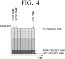
- FIG. 4 is a view illustrating dividing a spectrogram of a damaged audio signal by data for each frequency band according to an embodiment.
- the processor 120 may divide the first spectrogram of a predetermined time zone by frequency bands (first frequency band to N th frequency band), identify the first spectrogram in a frame unit of a predetermined time interval, and divide the first spectrogram into a first frame to a K th frame by frame units. That is, the first to K th frames are grouped in units input to the CNN, and one group can form K time slots.
- the K th frame of the first spectrogram corresponds to the current frame to be reconstructed.
- the processor 120 may perform reconstruction on the amplitude component of the entire frequency band of the first spectrogram, or may input only the data corresponding to the frequency band (high frequency band) above a predetermined magnitude among the frequency bands of the first spectrogram to the CNN, and maintain the data corresponding to the frequency band (low frequency band) below the predetermined magnitude without reconstructing.
- the processor 120 may apply a plurality of filters stored in the storage 110 relative to the first spectrogram input to each CNN for each frequency band and acquire the second spectrogram by merging output values of each CNN to which a plurality of filters are applied.
- the processor 120 acquires the reconstructed audio signal based on the second spectrogram acquired as shown above.
- FIG. 5 is a view illustrating a method for reconstructing a damaged audio signal using CNN according to an embodiment.
- data corresponding to the spectrogram of the first frequency band to the K th frequency band, among the divided frequency bands, are input to each of the first CNN to the K th CNN forming the first layer, respectively.
- the spectrogram of the first frequency band is input to the first CNN and is filtered by the pre-trained filters 11 to 1K corresponding to the first CNN.
- the spectrogram of the second frequency band is input to the second CNN and is filtered by the pre-trained filters 21 to 2K corresponding to the second CNN.
- the spectrogram of the K th frequency band is input to the K th CNN and is filtered by the pre-trained filters K0 to KK corresponding to the K th CNN.
- each CNN the number of filters corresponding to the number (K) of the divided frequency bands is applied to the spectrogram of each frequency band.
- filters 11, 21 to K1 of each CNN are filters trained based on the first frequency band
- filters 12, 22 to K2 are filters trained based on the second frequency band.
- the filters 1K, 2K to KK of each CNN refer to filters trained based on the K th frequency band.
- each filter has the same size.
- the filter value is determined by combining the spectrogram of the first frequency band generated by adding the result of 11, 21..., and K1, and the result of combining the spectrogram of the K th frequency band generated by adding the result of 1K, 2K, and KK. If the filter value is determined in this manner, the adjacent spectrum may be considered on the time axis, and the signal generation may be performed in consideration of the entire frequency band. Therefore, according to an embodiment, a local time relationship may be processed in consideration of a global frequency relationship.
- the filtering process may be performed through a plurality of layers, such as a second layer and a third layer in the same manner as the first layer. That is, by stacking a plurality of layers to configure the final network, each of the predefined filters may be trained in a direction that minimizes the error between the desired target spectrum and the processed spectrum based on the result of the entire layer.
- the processor 120 may acquire the second spectrogram corresponding to the first frequency band by merging output values in which the spectrogram of the first to K th frequency bands in each CNN are filtered by filters 11 to K1 that are trained based on the first frequency band.
- the processor 120 may acquire the second spectrogram corresponding to the second frequency band by merging the output values in which the spectrogram of the first to K th frequency bands in each CNN is filtered by filters 12 to K2 trained by the second frequency band.
- the processor 120 may acquire the second spectrogram corresponding to the K th frequency band by merging the output values in which the spectrogram of the first to K th frequency bands in each CNN is filtered based on filters 1K to KK that are trained based on the K th frequency band.
- the processor 120 may acquire the second spectrogram corresponding to the entire frequency band accordingly.
- the second spectrogram may have the same magnitude as the first spectrogram.
- the second spectrogram may have a smaller magnitude than the first spectrogram. For example, if the magnitude of the first spectrogram is 8, that is, when the first spectrogram consists of eight frames, if the size of the filter is 2, the magnitude of the second spectrogram becomes "7.” If padding is applied, the magnitude of the second spectrogram is maintained to be "8.”
- a sigmoid function may be applied to the result value output from each layer of the plurality of CNNs or the result value (feature map) output from the final layer.
- a sigmoid gate to which an output value filtered by each filter is input to the end of each CNN in each layer or final layer can be additionally included.
- the sigmoid gate may be disposed at each terminal through which an output value by a filter applied at each CNN of a plurality of layers is output.
- L number of filters may be applied to the spectrogram of each frequency band, instead of the K number of frequency bands divided in each CNN.
- the output second spectrogram may be data in which frequency is extended to the L frequency band.
- FIG. 8 is a view illustrating a method for designing CNN for reconstructing a damaged audio signal according to an embodiment.
- the processor 120 performs normalization on the spectrogram (first spectrogram) of the damaged audio signal, and extracts the amplitude component in the first spectrogram for which normalization is performed.
- the processor 120 may enter input data corresponding to an amplitude component of the extracted first spectrogram into a plurality of CNN layers comprised of at least one CNN.
- the input data may pass through a plurality of CNN layers.
- a first layer 81 and a second layer 82 of the plurality of CNN layers maintain the magnitude of the input data by padding, and a third layer 83 may reduce the magnitude of the input data passing through the second layer 82 to 6.
- the fourth layer 84 may reduce the size of the input data passing through the third layer 83 to 4.
- the fifth layer 85 may reduce the size of the input data passing through the fourth layer 84 to 2
- the sixth layer 86 may reduce the size of the input data passing through the fifth layer 85 to 1.
- the sizes of the filter that are applied to input data by a plurality of CNN layers are different from each other, and a plurality of CNN layers may be disposed to make output data having the size of 1 be finally outputted.
- the processor 120 may perform de-normalization of the output data passing through the plurality of CNN layers to acquire reconstructed data of the input data corresponding to the amplitude component.
- the processor 120 may perform de-normalization with respect to the output data using the stored normalization information when normalization is performed on the input data.
- FIG. 9 is a flowchart to describe a method for controlling an electronic apparatus according to an embodiment.
- a first spectrogram corresponding to a damaged audio signal is acquired in operation S910.
- the damaged audio signal may be input, and the input audio signal may be transformed to a first spectrogram based on time and frequency.
- the first spectrogram is input to the corresponding CNN for each frequency band in operation S920.
- the first spectrogram is identified in a frame unit, and a current frame and a predetermined number of previous frames are grouped and input into a corresponding CNN for each frequency band.
- a magnitude component may be acquired in the first spectrogram and input to a corresponding CNN for each frequency band.
- a frequency band that is greater than or equal to a predetermined magnitude among the frequency bands of the first spectrogram may be input to the corresponding CNN.
- a plurality of filters trained in each of the CNNs corresponding to each frequency band are applied to the input first spectrogram in operation S930.
- the output values of each CNN to which the plurality of filters are applied are merged to acquire a second spectrogram in operation S940.
- the output values of each CNN may be merged to acquire a reconstructed current frame.
- a first spectrogram for each frequency band to which a plurality of filters are applied is input to a sigmoid gate, and a first spectrogram for each frequency band outputted from the sigmoid gate may be merged to acquire a second spectrogram.
- the second spectrogram may also be acquired by combining the phase component of the first spectrogram and the magnitude component compensated by the CNN.
- the reconstructed audio signal is acquired based on the second spectrogram in operation S950.
- the second spectrogram may be inverse-transformed into an audio signal based on time and magnitude to acquire a reconstructed audio signal.
- even a sound source degraded due to compression can enable a user to enjoy a sound in a level of an original sound, and the waste of radio resources due to high bandwidth data transmission may be reduced. Accordingly, an audio device owned by a user may be fully utilized.
- the controlling method according to the various embodiments described above can be implemented as a program and stored in various recording media. That is, a computer program that can be processed by various processors to execute the various controlling methods described above may be used in a state stored in a recording medium.
- a non-transitory computer readable medium storing there in a program for performing the steps of acquiring a first spectrogram corresponding to a damaged audio signal, inputting a first spectrogram to a corresponding CNN for each frequency band, applying a plurality of filters trained in each of the CNN corresponding to each frequency band in the input first spectrogram, merging the output values of each CNN to which the plurality of filters are applied to acquire a second spectrogram, and acquiring the reconstructed audio signal based on the second spectrogram may be provided.
- the non-transitory computer readable medium refers to a medium that stores data semi-permanently rather than storing data for a very short time, such as a register, a cache, a memory or etc., and is readable by an apparatus.
- the aforementioned various applications or programs may be stored in the non-transitory computer readable medium, for example, a compact disc (CD), a digital versatile disc (DVD), a hard disc, a Blu-ray disc, a universal serial bus (USB), a memory card, a read only memory (ROM), and the like, and may be provided.
Landscapes
- Engineering & Computer Science (AREA)
- Physics & Mathematics (AREA)
- Health & Medical Sciences (AREA)
- Computational Linguistics (AREA)
- Multimedia (AREA)
- Acoustics & Sound (AREA)
- Human Computer Interaction (AREA)
- Audiology, Speech & Language Pathology (AREA)
- Signal Processing (AREA)
- Artificial Intelligence (AREA)
- Evolutionary Computation (AREA)
- Theoretical Computer Science (AREA)
- Quality & Reliability (AREA)
- Biophysics (AREA)
- General Physics & Mathematics (AREA)
- Mathematical Physics (AREA)
- Software Systems (AREA)
- General Engineering & Computer Science (AREA)
- Computing Systems (AREA)
- Molecular Biology (AREA)
- General Health & Medical Sciences (AREA)
- Data Mining & Analysis (AREA)
- Biomedical Technology (AREA)
- Life Sciences & Earth Sciences (AREA)
- Spectroscopy & Molecular Physics (AREA)
- Circuit For Audible Band Transducer (AREA)
Claims (15)
- Elektronische Vorrichtung (100), die Folgendes umfasst:einen Speicher (110) zum Speichern einer Vielzahl von Filtern, die in jedem einer Vielzahl von neuronalen Faltungsnetzwerken, CNNs, trainiert werden, die jeweils einer Vielzahl von Frequenzbändern eines ersten Spektrogramms entsprechen, das einem beschädigten Audiosignal entspricht, wobei die Vielzahl von Filtern in jedem CNN jeweils der Vielzahl von Frequenzbändern entspricht; undeinen Prozessor (120), der konfiguriert ist zum:Erfassen des ersten Spektrogramms,Eingeben jedes der Vielzahl von Frequenzbändern des ersten Spektrogramms in ein entsprechendes eines der Vielzahl von CNNs, um die Vielzahl von Filtern, die in dem entsprechenden einen der Vielzahl von CNNs trainiert werden, auf das Frequenzband anzuwenden, das in das entsprechende eine der Vielzahl von CNNs eingegeben wird,Erfassen eines zweiten Spektrogramms der Vielzahl von Frequenzbändern, wobei jedes Frequenzband des zweiten Spektrogramms durch eine Summierung von Ausgangswerten der Filter erfasst wird, die demselben jeweiligen Frequenzband entsprechen, undErfassen eines auf der Grundlage des zweiten Spektrogramms rekonstruiertem Audiosignals.
- Elektronische Vorrichtung (100) nach Anspruch 1, wobei:die Vielzahl von CNNs ein erstes CNN, in das ein erstes Frequenzband des ersten Spektrogramms eingegeben wird, und ein zweites CNN, in das ein zweites Frequenzband des ersten Spektrogramms eingegeben wird, umfasst,die Vielzahl von Filtern einen ersten Filter und einen zweiten Filter, die in dem ersten CNN trainiert werden, und einen dritten Filter und einen vierten Filter, die in dem zweiten CNN trainiert werden, umfasst,der erste Filter und der dritte Filter auf der Grundlage des ersten Frequenzbandes trainiert werden und der zweite Filter und der vierte Filter auf der Grundlage des zweiten Frequenzbandes trainiert werden,der Prozessor (120) ferner konfiguriert ist, um :
das erste Frequenzband des zweiten Spektrogramms durch eine Summierung von Ausgangswerten des ersten CNN, in dem der erste Filter angewendet wird, und von Ausgangswerten des zweiten CNN, in dem der dritte Filter angewendet wird, zu erfassen, und das zweite Frequenzband des zweiten Spektrogramms durch eine Summierung von Ausgangswerten des ersten CNN, in dem der zweite Filter angewendet wird, und von Ausgangswerten des zweiten CNN, in dem der vierte Filter angewendet wird, zu erfassen. - Elektronische Vorrichtung (100) nach Anspruch 1, wobei der Prozessor (120) ferner konfiguriert ist, um:das erste Spektrogramm in einer Rahmeneinheit eines vorbestimmten Zeitintervalls zu identifizieren,das erste Spektrogramm in einen ersten Rahmen bis zu einem Kten Rahmen durch Rahmeneinheiten zu unterteilen.
- Elektronische Vorrichtung (100) nach Anspruch 1, wobei die Vielzahl der CNNs eine erste CNN-Schicht bilden,
wobei der Prozessor (120) weiterhin konfiguriert ist zum:
Erfassen des zweiten Spektrogramms durch Eingeben von Ausgangswerten der ersten CNN-Schicht in eine zweite CNN-Schicht, die eine Vielzahl anderer CNNs umfasst, wobei eine Vielzahl von Filtern in jedem der CNNs der zweiten CNN-Schicht trainiert wird, die Vielzahl von Filtern in jedem CNN der zweiten CNN-Schicht jeweils der Vielzahl von Frequenzbändern entspricht, und wobei jedes Frequenzband des zweiten Spektrogramms durch eine Summierung von Ausgangswerten der Filter der zweiten CNN-Schicht erfasst wird, die demselben jeweiligen Frequenzband entsprechen. - Elektronische Vorrichtung (100) nach Anspruch 1, wobei der Prozessor (120) ferner konfiguriert ist, um die Ausgangswerte der Filter jeweils in eine Vielzahl von Sigmoid-Gates einzugeben und das zweite Spektrogramm durch eine Summierung der von der Vielzahl von Sigmoid-Gates ausgegebenen Werte zu erfassen, die demselben jeweiligen Frequenzband entsprechen.
- Elektronische Vorrichtung (100) nach Anspruch 1, die außerdem Folgendes umfasst:eine Eingabevorrichtung,wobei der Prozessor (120) weiterhin konfiguriert ist, um:das beschädigte Audiosignal, das über die Eingabevorrichtung eingegeben wird, auf der Grundlage von Zeit und Frequenz in das erste Spektrogramm umzuwandeln unddas rekonstruierte Audiosignal durch inverse Transformation des zweiten Spektrogramms in ein Audiosignal auf der Grundlage von Zeit und Betrag zu erfassen.
- Elektronische Vorrichtung (100) nach Anspruch 6, wobei der Prozessor (120) ferner konfiguriert ist, um eine kompensierte Betragskomponente zu erfassen, indem eine Betragskomponente des ersten Spektrogramms erfasst und jedes der Frequenzbänder der erfassten Betragskomponente, die den Frequenzbändern des ersten Spektrogramms entsprechen, in ein entsprechendes eines der Vielzahl von CNNs eingegeben wird, und das zweite Spektrogramm zu erfassen, indem eine Phasenkomponente des ersten Spektrogramms und die kompensierte Betragskomponente, die durch die Ausgangswerte der Summierung dargestellt wird, kombiniert werden.
- Elektronische Vorrichtung (100) nach Anspruch 1, wobei der Prozessor (120) so konfiguriert ist, dass er nur Frequenzbänder, die größer oder gleich einer vorbestimmten Frequenz sind, aus der Vielzahl von Frequenzbändern des ersten Spektrogramms in die entsprechenden CNNs eingibt.
- Elektronische Vorrichtung (100) nach Anspruch 1, wobei der Prozessor (120) ferner konfiguriert ist, um das erste Spektrogramm zu normalisieren und jedes der Vielzahl von Frequenzbändern des normalisierten ersten Spektrogramms in das entsprechende eine der Vielzahl von CNNs einzugeben, das zweite Spektrogramm zu denormalisieren und das rekonstruierte Audiosignal auf der Grundlage des denormalisierten zweiten Spektrogramms zu erfassen.
- Verfahren zur Steuerung einer elektronischen Vorrichtung (100), wobei das Verfahren umfasst:Erfassen eines ersten Spektrogramms, das einem beschädigten Audiosignal entspricht, einer Vielzahl von neuronalen Faltungsnetzwerken, CNNs, die jeweils einer Vielzahl von Frequenzbändern des ersten Spektrogramms entsprechen, einer Vielzahl von Filtern in jedem CNN, die jeweils der Vielzahl von Frequenzbändern entsprechen;Eingeben jedes der Vielzahl von Frequenzbändern des ersten Spektrogramms in ein entsprechendes eines aus der Vielzahl von CNNs, um die Vielzahl von Filtern, die in dem entsprechenden einen aus der Vielzahl von CNNs trainiert werden, auf das Frequenzband anzuwenden, das in das entsprechende eine aus der Vielzahl von CNNs eingegeben wird;Erfassen eines zweiten Spektrogramms der Vielzahl von Frequenzbändern, wobei jedes Frequenzband des zweiten Spektrogramms durch eine Summierung von Ausgangswerten der Filter erfasst wird, die dem gleichen jeweiligen Frequenzband entsprechen; undErfassen eines auf der Grundlage des zweiten Spektrogramms rekonstruierten Audiosignals.
- Verfahren nach Anspruch 10, wobei:die Vielzahl von CNNs ein erstes CNN, in das ein erstes Frequenzband des ersten Spektrogramms eingegeben wird, und ein zweites CNN, in das ein zweites Frequenzband des ersten Spektrogramms eingegeben wird, umfasst,die Vielzahl von Filtern einen ersten Filter und einen zweiten Filter, die in dem ersten CNN trainiert werden, und einen dritten Filter und einen vierten Filter, die in dem zweiten CNN trainiert werden, umfasst,der erste Filter und der dritte Filter auf der Grundlage des ersten Frequenzbandes trainiert werden und der zweite Filter und der vierte Filter auf der Grundlage des zweiten Frequenzbandes trainiert werden,das Erfassen des zweiten Spektrogramms das Erfassen des ersten Frequenzbandes des zweiten Spektrogramms durch eine Summierung von Ausgangswerten des ersten CNN, in dem der erste Filter angewendet wird, und Ausgangswerten des zweiten CNN, in dem der dritte Filter angewendet wird, und das Erfassen des zweiten Frequenzbandes des zweiten Spektrogramms durch eine Summierung von Ausgangswerten des ersten CNN, in dem der zweite Filter angewendet wird, und Ausgangswerten des zweiten CNN, in dem der vierte Filter angewendet wird, umfasst.
- Verfahren nach Anspruch 10, wobei das Eingeben das Identifizieren des ersten Spektrogramms in einer Rahmeneinheit eines vorbestimmten Zeitintervalls, das Unterteilen des ersten Spektrogramms in einen ersten Rahmen bis zu einem Kten Rahmen durch Rahmeneinheiten umfasst.
- Verfahren nach Anspruch 10, wobei die Vielzahl von CNNs eine erste CNN-Schicht bilden, und
wobei das Erfassen des zweiten Spektrogramms das Erfassen des zweiten Spektrogramms durch Eingeben von Ausgangswerten der ersten CNN-Schicht in eine zweite CNN-Schicht, die eine Vielzahl anderer CNNs umfasst, umfasst, wobei eine Vielzahl von Filtern in jedem der CNNs der zweiten CNN-Schicht trainiert wird, die Vielzahl von Filtern in jedem CNN der zweiten CNN-Schicht jeweils der Vielzahl von Frequenzbändern entspricht, und wobei jedes Frequenzband des zweiten Spektrogramms durch eine Summierung von Ausgangswerten der Filter der zweiten CNN-Schicht, die dem gleichen jeweiligen Frequenzband entsprechen, erfasst wird. - Verfahren nach Anspruch 10, wobei das Erfassen des zweiten Spektrogramms das Eingeben der Ausgangswerte der Filter in eine Vielzahl von jeweiligen Sigmoid-Gates und das Erfassen des zweiten Spektrogramms durch eine Summierung der von der Vielzahl von Sigmoid-Gates ausgegebenen Werte, die demselben jeweiligen Frequenzband entsprechen, umfasst.
- Nicht-flüchtiges computerlesbares Medium, in dem eine Computerinstruktion gespeichert ist, die, wenn sie von einem Prozessor (120) einer elektronischen Vorrichtung (100) ausgeführt wird, den Prozessor veranlasst, die folgenden Verfahrensschritte durchzuführen:Erfassen eines ersten Spektrogramms, das einem beschädigten Audiosignal entspricht, einer Vielzahl von neuronalen Faltungsnetzwerken, CNNs, die jeweils einer Vielzahl von Frequenzbändern des ersten Spektrogramms entsprechen, einer Vielzahl von Filtern in jedem CNN, die jeweils der Vielzahl von Frequenzbändern entsprechen;Eingeben jedes der Vielzahl von Frequenzbändern des ersten Spektrogramms in ein entsprechendes eines aus der Vielzahl von CNNs, um die Vielzahl von Filtern, die in dem entsprechenden einen aus der Vielzahl von CNNs trainiert werden, auf das Frequenzband anzuwenden, das in das entsprechende eine aus der Vielzahl von CNNs eingegeben wird;Erfassen eines zweiten Spektrogramms der Vielzahl von Frequenzbändern, wobei jedes Frequenzband des zweiten Spektrogramms durch eine Summierung von Ausgangswerten der Filter erfasst wird, die dem gleichen jeweiligen Frequenzband entsprechen; undErfassen eines auf der Grundlage des zweiten Spektrogramms rekonstruierten Audiosignals.
Applications Claiming Priority (2)
| Application Number | Priority Date | Filing Date | Title |
|---|---|---|---|
| US201762576887P | 2017-10-25 | 2017-10-25 | |
| PCT/KR2018/008149 WO2019083130A1 (ko) | 2017-10-25 | 2018-07-19 | 전자 장치 및 그 제어 방법 |
Publications (4)
| Publication Number | Publication Date |
|---|---|
| EP3664084A1 EP3664084A1 (de) | 2020-06-10 |
| EP3664084A4 EP3664084A4 (de) | 2020-10-21 |
| EP3664084B1 true EP3664084B1 (de) | 2024-04-17 |
| EP3664084C0 EP3664084C0 (de) | 2024-04-17 |
Family
ID=66247937
Family Applications (1)
| Application Number | Title | Priority Date | Filing Date |
|---|---|---|---|
| EP18870750.9A Active EP3664084B1 (de) | 2017-10-25 | 2018-07-19 | Elektronische vorrichtung und steuerungsverfahren dafür |
Country Status (5)
| Country | Link |
|---|---|
| US (1) | US11282535B2 (de) |
| EP (1) | EP3664084B1 (de) |
| KR (1) | KR102648122B1 (de) |
| CN (1) | CN111201569B (de) |
| WO (1) | WO2019083130A1 (de) |
Families Citing this family (10)
| Publication number | Priority date | Publication date | Assignee | Title |
|---|---|---|---|---|
| WO2020207593A1 (en) | 2019-04-11 | 2020-10-15 | Fraunhofer-Gesellschaft zur Förderung der angewandten Forschung e.V. | Audio decoder, apparatus for determining a set of values defining characteristics of a filter, methods for providing a decoded audio representation, methods for determining a set of values defining characteristics of a filter and computer program |
| US11763932B2 (en) * | 2019-11-14 | 2023-09-19 | International Business Machines Corporation | Classifying images using deep neural network with integrated acquisition information |
| CN113049922B (zh) * | 2020-04-22 | 2022-11-15 | 青岛鼎信通讯股份有限公司 | 一种采用卷积神经网络的故障电弧信号检测方法 |
| EP3917015B8 (de) | 2020-05-29 | 2024-04-24 | Rohde & Schwarz GmbH & Co. KG | Verfahren zum komprimieren von digitalen signaldaten und signalkompressormodul |
| CN111723714B (zh) * | 2020-06-10 | 2023-11-03 | 上海商汤智能科技有限公司 | 识别人脸图像真伪的方法、装置及介质 |
| EP4229634A1 (de) * | 2020-10-16 | 2023-08-23 | Dolby Laboratories Licensing Corporation | Prädiktor für ein allgemeines medienneuronales netzwerk und generatives modell mit solch einem prädiktor |
| US20220365799A1 (en) * | 2021-05-17 | 2022-11-17 | Iyo Inc. | Using machine learning models to simulate performance of vacuum tube audio hardware |
| CN114070679B (zh) * | 2021-10-25 | 2023-05-23 | 中国电子科技集团公司第二十九研究所 | 一种面向脉冲智能分类的频相特征分析方法 |
| CN116631420A (zh) * | 2023-06-08 | 2023-08-22 | 中国工商银行股份有限公司 | 音频修复方法、装置、计算机设备和存储介质 |
| CN117257324B (zh) * | 2023-11-22 | 2024-01-30 | 齐鲁工业大学(山东省科学院) | 基于卷积神经网络和ecg信号的房颤检测方法 |
Family Cites Families (23)
| Publication number | Priority date | Publication date | Assignee | Title |
|---|---|---|---|---|
| IL154397A0 (en) | 2000-08-14 | 2003-09-17 | Clear Audio Ltd | Voice enhancement system |
| KR100608062B1 (ko) * | 2004-08-04 | 2006-08-02 | 삼성전자주식회사 | 오디오 데이터의 고주파수 복원 방법 및 그 장치 |
| US7593535B2 (en) | 2006-08-01 | 2009-09-22 | Dts, Inc. | Neural network filtering techniques for compensating linear and non-linear distortion of an audio transducer |
| KR101377135B1 (ko) | 2007-01-02 | 2014-03-21 | 삼성전자주식회사 | 오디오 신호의 저주파 및 중주파 성분 보강 방법 및 그장치 |
| KR20080072224A (ko) | 2007-02-01 | 2008-08-06 | 삼성전자주식회사 | 오디오 부호화 및 복호화 장치와 그 방법 |
| KR101456866B1 (ko) | 2007-10-12 | 2014-11-03 | 삼성전자주식회사 | 혼합 사운드로부터 목표 음원 신호를 추출하는 방법 및장치 |
| CN102652336B (zh) * | 2009-12-28 | 2015-02-18 | 三菱电机株式会社 | 声音信号复原装置以及声音信号复原方法 |
| KR101666465B1 (ko) | 2010-07-22 | 2016-10-17 | 삼성전자주식회사 | 다채널 오디오 신호 부호화/복호화 장치 및 방법 |
| KR20120072243A (ko) | 2010-12-23 | 2012-07-03 | 한국전자통신연구원 | 음향/음성 인식을 위한 잡음 제거 장치 및 그 방법 |
| US9037458B2 (en) | 2011-02-23 | 2015-05-19 | Qualcomm Incorporated | Systems, methods, apparatus, and computer-readable media for spatially selective audio augmentation |
| WO2013149123A1 (en) * | 2012-03-30 | 2013-10-03 | The Ohio State University | Monaural speech filter |
| US9135920B2 (en) | 2012-11-26 | 2015-09-15 | Harman International Industries, Incorporated | System for perceived enhancement and restoration of compressed audio signals |
| US20150162014A1 (en) | 2013-12-06 | 2015-06-11 | Qualcomm Incorporated | Systems and methods for enhancing an audio signal |
| WO2015122785A1 (en) | 2014-02-14 | 2015-08-20 | Derrick Donald James | System for audio analysis and perception enhancement |
| US10460736B2 (en) * | 2014-11-07 | 2019-10-29 | Samsung Electronics Co., Ltd. | Method and apparatus for restoring audio signal |
| BR112017018145B1 (pt) * | 2015-02-26 | 2023-11-28 | Fraunhofer-Gesellschaft Zur Foerderung Der Angewandten Forschung E. V | Aparelho e método para processamento de um sinal de áudio para obter um sinal de áudio processado utilizando um envelope de domínio de tempo alvo |
| US9697826B2 (en) * | 2015-03-27 | 2017-07-04 | Google Inc. | Processing multi-channel audio waveforms |
| US9666183B2 (en) * | 2015-03-27 | 2017-05-30 | Qualcomm Incorporated | Deep neural net based filter prediction for audio event classification and extraction |
| US9805305B2 (en) * | 2015-08-07 | 2017-10-31 | Yahoo Holdings, Inc. | Boosted deep convolutional neural networks (CNNs) |
| US20170140260A1 (en) * | 2015-11-17 | 2017-05-18 | RCRDCLUB Corporation | Content filtering with convolutional neural networks |
| DE102016219931A1 (de) * | 2016-10-13 | 2018-04-19 | Airbus Operations Gmbh | System und Verfahren zum Entdecken von Radom-Schäden |
| CN106847294B (zh) * | 2017-01-17 | 2018-11-30 | 百度在线网络技术(北京)有限公司 | 基于人工智能的音频处理方法和装置 |
| CN106952649A (zh) * | 2017-05-14 | 2017-07-14 | 北京工业大学 | 基于卷积神经网络和频谱图的说话人识别方法 |
-
2018
- 2018-07-19 US US16/757,070 patent/US11282535B2/en active Active
- 2018-07-19 WO PCT/KR2018/008149 patent/WO2019083130A1/ko not_active Ceased
- 2018-07-19 EP EP18870750.9A patent/EP3664084B1/de active Active
- 2018-07-19 KR KR1020197035467A patent/KR102648122B1/ko active Active
- 2018-07-19 CN CN201880066283.6A patent/CN111201569B/zh active Active
Also Published As
| Publication number | Publication date |
|---|---|
| US11282535B2 (en) | 2022-03-22 |
| KR20200063100A (ko) | 2020-06-04 |
| EP3664084A4 (de) | 2020-10-21 |
| WO2019083130A1 (ko) | 2019-05-02 |
| EP3664084A1 (de) | 2020-06-10 |
| CN111201569A (zh) | 2020-05-26 |
| KR102648122B1 (ko) | 2024-03-19 |
| US20200342893A1 (en) | 2020-10-29 |
| EP3664084C0 (de) | 2024-04-17 |
| CN111201569B (zh) | 2023-10-20 |
Similar Documents
| Publication | Publication Date | Title |
|---|---|---|
| EP3664084B1 (de) | Elektronische vorrichtung und steuerungsverfahren dafür | |
| CN110600017B (zh) | 语音处理模型的训练方法、语音识别方法、系统及装置 | |
| CN112949708A (zh) | 情绪识别方法、装置、计算机设备和存储介质 | |
| Abouzid et al. | Signal speech reconstruction and noise removal using convolutional denoising audioencoders with neural deep learning | |
| Parekh et al. | Listen to interpret: Post-hoc interpretability for audio networks with nmf | |
| Mukhutdinov et al. | Deep learning models for single-channel speech enhancement on drones | |
| KR20200018154A (ko) | 브이에이이 모델 기반의 반지도 학습을 이용한 음향 정보 인식 방법 및 시스템 | |
| Yechuri et al. | A nested u-net with efficient channel attention and d3net for speech enhancement | |
| CN116705013B (zh) | 语音唤醒词的检测方法、装置、存储介质和电子设备 | |
| AL-Shakarchy et al. | Audio verification in forensic investigation using light deep neural network | |
| US20250372084A1 (en) | Speaker identification, verification, and diarization using neural networks for conversational ai systems and applications | |
| Della Libera et al. | Focal modulation networks for interpretable sound classification | |
| Oo et al. | Fusion of Log-Mel Spectrogram and GLCM feature in acoustic scene classification | |
| CN113504891B (zh) | 一种音量调节方法、装置、设备以及存储介质 | |
| Nasim et al. | Audio Source Separation: Advances and Challenges | |
| Returi et al. | A method of speech signal analysis using multi-level wavelet transform | |
| CN116561584B (zh) | 基于变分量子电路的语音隐私推断方法、装置及存储介质 | |
| Kaur et al. | Maximum likelihood based estimation with quasi oppositional chemical reaction optimization algorithm for speech signal enhancement | |
| Mirzaei et al. | Acoustic scene classification with multi-temporal complex modulation spectrogram features and a convolutional LSTM network | |
| Agrawal et al. | Comparison of Unsupervised Modulation Filter Learning Methods for ASR. | |
| Joshi et al. | An efficient approach to lip-reading with 3d cnn and bi-lstm fusion model | |
| CN116092465B (zh) | 一种车载音频降噪方法、装置、存储介质和电子设备 | |
| Gul et al. | Single channel speech enhancement by colored spectrograms | |
| Oo et al. | Acoustic Scene Classification using Attention based Deep Learning Model | |
| Asikainen | ACOUSTIC SCENE CLASSIFICATION WITH INTERPRETABLE DEEP NEURAL NETWORKS |
Legal Events
| Date | Code | Title | Description |
|---|---|---|---|
| STAA | Information on the status of an ep patent application or granted ep patent |
Free format text: STATUS: THE INTERNATIONAL PUBLICATION HAS BEEN MADE |
|
| PUAI | Public reference made under article 153(3) epc to a published international application that has entered the european phase |
Free format text: ORIGINAL CODE: 0009012 |
|
| STAA | Information on the status of an ep patent application or granted ep patent |
Free format text: STATUS: REQUEST FOR EXAMINATION WAS MADE |
|
| 17P | Request for examination filed |
Effective date: 20200305 |
|
| AK | Designated contracting states |
Kind code of ref document: A1 Designated state(s): AL AT BE BG CH CY CZ DE DK EE ES FI FR GB GR HR HU IE IS IT LI LT LU LV MC MK MT NL NO PL PT RO RS SE SI SK SM TR |
|
| AX | Request for extension of the european patent |
Extension state: BA ME |
|
| REG | Reference to a national code |
Ref country code: DE Ref legal event code: R079 Free format text: PREVIOUS MAIN CLASS: G10L0019000000 Ipc: G10L0021020000 Ref document number: 602018068339 Country of ref document: DE |
|
| A4 | Supplementary search report drawn up and despatched |
Effective date: 20200918 |
|
| RIC1 | Information provided on ipc code assigned before grant |
Ipc: G10L 25/30 20130101ALI20200914BHEP Ipc: G10L 19/26 20130101ALI20200914BHEP Ipc: G10L 19/02 20130101ALI20200914BHEP Ipc: G10L 21/02 20130101AFI20200914BHEP |
|
| DAV | Request for validation of the european patent (deleted) | ||
| DAX | Request for extension of the european patent (deleted) | ||
| STAA | Information on the status of an ep patent application or granted ep patent |
Free format text: STATUS: EXAMINATION IS IN PROGRESS |
|
| 17Q | First examination report despatched |
Effective date: 20210702 |
|
| GRAP | Despatch of communication of intention to grant a patent |
Free format text: ORIGINAL CODE: EPIDOSNIGR1 |
|
| STAA | Information on the status of an ep patent application or granted ep patent |
Free format text: STATUS: GRANT OF PATENT IS INTENDED |
|
| INTG | Intention to grant announced |
Effective date: 20231115 |
|
| GRAS | Grant fee paid |
Free format text: ORIGINAL CODE: EPIDOSNIGR3 |
|
| GRAA | (expected) grant |
Free format text: ORIGINAL CODE: 0009210 |
|
| STAA | Information on the status of an ep patent application or granted ep patent |
Free format text: STATUS: THE PATENT HAS BEEN GRANTED |
|
| AK | Designated contracting states |
Kind code of ref document: B1 Designated state(s): AL AT BE BG CH CY CZ DE DK EE ES FI FR GB GR HR HU IE IS IT LI LT LU LV MC MK MT NL NO PL PT RO RS SE SI SK SM TR |
|
| REG | Reference to a national code |
Ref country code: GB Ref legal event code: FG4D |
|
| REG | Reference to a national code |
Ref country code: CH Ref legal event code: EP |
|
| REG | Reference to a national code |
Ref country code: IE Ref legal event code: FG4D Ref country code: DE Ref legal event code: R096 Ref document number: 602018068339 Country of ref document: DE |
|
| U01 | Request for unitary effect filed |
Effective date: 20240429 |
|
| U07 | Unitary effect registered |
Designated state(s): AT BE BG DE DK EE FI FR IT LT LU LV MT NL PT SE SI Effective date: 20240506 |
|
| U20 | Renewal fee for the european patent with unitary effect paid |
Year of fee payment: 7 Effective date: 20240624 |
|
| PG25 | Lapsed in a contracting state [announced via postgrant information from national office to epo] |
Ref country code: IS Free format text: LAPSE BECAUSE OF FAILURE TO SUBMIT A TRANSLATION OF THE DESCRIPTION OR TO PAY THE FEE WITHIN THE PRESCRIBED TIME-LIMIT Effective date: 20240817 |
|
| PG25 | Lapsed in a contracting state [announced via postgrant information from national office to epo] |
Ref country code: HR Free format text: LAPSE BECAUSE OF FAILURE TO SUBMIT A TRANSLATION OF THE DESCRIPTION OR TO PAY THE FEE WITHIN THE PRESCRIBED TIME-LIMIT Effective date: 20240417 |
|
| PG25 | Lapsed in a contracting state [announced via postgrant information from national office to epo] |
Ref country code: GR Free format text: LAPSE BECAUSE OF FAILURE TO SUBMIT A TRANSLATION OF THE DESCRIPTION OR TO PAY THE FEE WITHIN THE PRESCRIBED TIME-LIMIT Effective date: 20240718 |
|
| PG25 | Lapsed in a contracting state [announced via postgrant information from national office to epo] |
Ref country code: ES Free format text: LAPSE BECAUSE OF FAILURE TO SUBMIT A TRANSLATION OF THE DESCRIPTION OR TO PAY THE FEE WITHIN THE PRESCRIBED TIME-LIMIT Effective date: 20240417 |
|
| PG25 | Lapsed in a contracting state [announced via postgrant information from national office to epo] |
Ref country code: PL Free format text: LAPSE BECAUSE OF FAILURE TO SUBMIT A TRANSLATION OF THE DESCRIPTION OR TO PAY THE FEE WITHIN THE PRESCRIBED TIME-LIMIT Effective date: 20240417 |
|
| PG25 | Lapsed in a contracting state [announced via postgrant information from national office to epo] |
Ref country code: PL Free format text: LAPSE BECAUSE OF FAILURE TO SUBMIT A TRANSLATION OF THE DESCRIPTION OR TO PAY THE FEE WITHIN THE PRESCRIBED TIME-LIMIT Effective date: 20240417 Ref country code: NO Free format text: LAPSE BECAUSE OF FAILURE TO SUBMIT A TRANSLATION OF THE DESCRIPTION OR TO PAY THE FEE WITHIN THE PRESCRIBED TIME-LIMIT Effective date: 20240717 Ref country code: IS Free format text: LAPSE BECAUSE OF FAILURE TO SUBMIT A TRANSLATION OF THE DESCRIPTION OR TO PAY THE FEE WITHIN THE PRESCRIBED TIME-LIMIT Effective date: 20240817 Ref country code: HR Free format text: LAPSE BECAUSE OF FAILURE TO SUBMIT A TRANSLATION OF THE DESCRIPTION OR TO PAY THE FEE WITHIN THE PRESCRIBED TIME-LIMIT Effective date: 20240417 Ref country code: GR Free format text: LAPSE BECAUSE OF FAILURE TO SUBMIT A TRANSLATION OF THE DESCRIPTION OR TO PAY THE FEE WITHIN THE PRESCRIBED TIME-LIMIT Effective date: 20240718 Ref country code: ES Free format text: LAPSE BECAUSE OF FAILURE TO SUBMIT A TRANSLATION OF THE DESCRIPTION OR TO PAY THE FEE WITHIN THE PRESCRIBED TIME-LIMIT Effective date: 20240417 Ref country code: RS Free format text: LAPSE BECAUSE OF FAILURE TO SUBMIT A TRANSLATION OF THE DESCRIPTION OR TO PAY THE FEE WITHIN THE PRESCRIBED TIME-LIMIT Effective date: 20240717 |
|
| REG | Reference to a national code |
Ref country code: DE Ref legal event code: R097 Ref document number: 602018068339 Country of ref document: DE |
|
| PG25 | Lapsed in a contracting state [announced via postgrant information from national office to epo] |
Ref country code: CZ Free format text: LAPSE BECAUSE OF FAILURE TO SUBMIT A TRANSLATION OF THE DESCRIPTION OR TO PAY THE FEE WITHIN THE PRESCRIBED TIME-LIMIT Effective date: 20240417 |
|
| PG25 | Lapsed in a contracting state [announced via postgrant information from national office to epo] |
Ref country code: SK Free format text: LAPSE BECAUSE OF FAILURE TO SUBMIT A TRANSLATION OF THE DESCRIPTION OR TO PAY THE FEE WITHIN THE PRESCRIBED TIME-LIMIT Effective date: 20240417 Ref country code: RO Free format text: LAPSE BECAUSE OF FAILURE TO SUBMIT A TRANSLATION OF THE DESCRIPTION OR TO PAY THE FEE WITHIN THE PRESCRIBED TIME-LIMIT Effective date: 20240417 |
|
| PG25 | Lapsed in a contracting state [announced via postgrant information from national office to epo] |
Ref country code: SM Free format text: LAPSE BECAUSE OF FAILURE TO SUBMIT A TRANSLATION OF THE DESCRIPTION OR TO PAY THE FEE WITHIN THE PRESCRIBED TIME-LIMIT Effective date: 20240417 |
|
| PG25 | Lapsed in a contracting state [announced via postgrant information from national office to epo] |
Ref country code: SM Free format text: LAPSE BECAUSE OF FAILURE TO SUBMIT A TRANSLATION OF THE DESCRIPTION OR TO PAY THE FEE WITHIN THE PRESCRIBED TIME-LIMIT Effective date: 20240417 Ref country code: SK Free format text: LAPSE BECAUSE OF FAILURE TO SUBMIT A TRANSLATION OF THE DESCRIPTION OR TO PAY THE FEE WITHIN THE PRESCRIBED TIME-LIMIT Effective date: 20240417 Ref country code: RO Free format text: LAPSE BECAUSE OF FAILURE TO SUBMIT A TRANSLATION OF THE DESCRIPTION OR TO PAY THE FEE WITHIN THE PRESCRIBED TIME-LIMIT Effective date: 20240417 Ref country code: CZ Free format text: LAPSE BECAUSE OF FAILURE TO SUBMIT A TRANSLATION OF THE DESCRIPTION OR TO PAY THE FEE WITHIN THE PRESCRIBED TIME-LIMIT Effective date: 20240417 |
|
| PG25 | Lapsed in a contracting state [announced via postgrant information from national office to epo] |
Ref country code: MC Free format text: LAPSE BECAUSE OF FAILURE TO SUBMIT A TRANSLATION OF THE DESCRIPTION OR TO PAY THE FEE WITHIN THE PRESCRIBED TIME-LIMIT Effective date: 20240417 |
|
| PLBE | No opposition filed within time limit |
Free format text: ORIGINAL CODE: 0009261 |
|
| STAA | Information on the status of an ep patent application or granted ep patent |
Free format text: STATUS: NO OPPOSITION FILED WITHIN TIME LIMIT |
|
| REG | Reference to a national code |
Ref country code: CH Ref legal event code: PL |
|
| 26N | No opposition filed |
Effective date: 20250120 |
|
| GBPC | Gb: european patent ceased through non-payment of renewal fee |
Effective date: 20240719 |
|
| PG25 | Lapsed in a contracting state [announced via postgrant information from national office to epo] |
Ref country code: CH Free format text: LAPSE BECAUSE OF NON-PAYMENT OF DUE FEES Effective date: 20240731 |
|
| PG25 | Lapsed in a contracting state [announced via postgrant information from national office to epo] |
Ref country code: GB Free format text: LAPSE BECAUSE OF NON-PAYMENT OF DUE FEES Effective date: 20240719 |
|
| PG25 | Lapsed in a contracting state [announced via postgrant information from national office to epo] |
Ref country code: IE Free format text: LAPSE BECAUSE OF NON-PAYMENT OF DUE FEES Effective date: 20240719 |
|
| U20 | Renewal fee for the european patent with unitary effect paid |
Year of fee payment: 8 Effective date: 20250723 |
|
| PG25 | Lapsed in a contracting state [announced via postgrant information from national office to epo] |
Ref country code: CY Free format text: LAPSE BECAUSE OF FAILURE TO SUBMIT A TRANSLATION OF THE DESCRIPTION OR TO PAY THE FEE WITHIN THE PRESCRIBED TIME-LIMIT; INVALID AB INITIO Effective date: 20180719 |