EP3664045A1 - Electronic key for a vehicle with a waterseal foam - Google Patents
Electronic key for a vehicle with a waterseal foam Download PDFInfo
- Publication number
- EP3664045A1 EP3664045A1 EP18210626.0A EP18210626A EP3664045A1 EP 3664045 A1 EP3664045 A1 EP 3664045A1 EP 18210626 A EP18210626 A EP 18210626A EP 3664045 A1 EP3664045 A1 EP 3664045A1
- Authority
- EP
- European Patent Office
- Prior art keywords
- waterseal
- foam
- electronic key
- cover
- battery
- Prior art date
- Legal status (The legal status is an assumption and is not a legal conclusion. Google has not performed a legal analysis and makes no representation as to the accuracy of the status listed.)
- Pending
Links
- 239000006260 foam Substances 0.000 title claims abstract description 93
- 239000000853 adhesive Substances 0.000 claims description 16
- 230000001070 adhesive effect Effects 0.000 claims description 16
- 239000003292 glue Substances 0.000 claims description 13
- XUIMIQQOPSSXEZ-UHFFFAOYSA-N Silicon Chemical compound [Si] XUIMIQQOPSSXEZ-UHFFFAOYSA-N 0.000 description 9
- 239000012528 membrane Substances 0.000 description 9
- 229910052710 silicon Inorganic materials 0.000 description 9
- 239000010703 silicon Substances 0.000 description 9
- RVCKCEDKBVEEHL-UHFFFAOYSA-N 2,3,4,5,6-pentachlorobenzyl alcohol Chemical compound OCC1=C(Cl)C(Cl)=C(Cl)C(Cl)=C1Cl RVCKCEDKBVEEHL-UHFFFAOYSA-N 0.000 description 7
- 230000006835 compression Effects 0.000 description 7
- 238000007906 compression Methods 0.000 description 7
- 239000002861 polymer material Substances 0.000 description 3
- 239000000463 material Substances 0.000 description 2
- 238000007789 sealing Methods 0.000 description 2
- 230000021615 conjugation Effects 0.000 description 1
- 238000010276 construction Methods 0.000 description 1
- 238000000034 method Methods 0.000 description 1
- 238000012986 modification Methods 0.000 description 1
- 230000004048 modification Effects 0.000 description 1
- 230000035939 shock Effects 0.000 description 1
- 239000007779 soft material Substances 0.000 description 1
- XLYOFNOQVPJJNP-UHFFFAOYSA-N water Substances O XLYOFNOQVPJJNP-UHFFFAOYSA-N 0.000 description 1
Images


Classifications
-
- G—PHYSICS
- G07—CHECKING-DEVICES
- G07C—TIME OR ATTENDANCE REGISTERS; REGISTERING OR INDICATING THE WORKING OF MACHINES; GENERATING RANDOM NUMBERS; VOTING OR LOTTERY APPARATUS; ARRANGEMENTS, SYSTEMS OR APPARATUS FOR CHECKING NOT PROVIDED FOR ELSEWHERE
- G07C9/00—Individual registration on entry or exit
- G07C9/00174—Electronically operated locks; Circuits therefor; Nonmechanical keys therefor, e.g. passive or active electrical keys or other data carriers without mechanical keys
- G07C9/00944—Details of construction or manufacture
-
- B—PERFORMING OPERATIONS; TRANSPORTING
- B60—VEHICLES IN GENERAL
- B60R—VEHICLES, VEHICLE FITTINGS, OR VEHICLE PARTS, NOT OTHERWISE PROVIDED FOR
- B60R25/00—Fittings or systems for preventing or indicating unauthorised use or theft of vehicles
- B60R25/20—Means to switch the anti-theft system on or off
- B60R25/24—Means to switch the anti-theft system on or off using electronic identifiers containing a code not memorised by the user
-
- G—PHYSICS
- G07—CHECKING-DEVICES
- G07C—TIME OR ATTENDANCE REGISTERS; REGISTERING OR INDICATING THE WORKING OF MACHINES; GENERATING RANDOM NUMBERS; VOTING OR LOTTERY APPARATUS; ARRANGEMENTS, SYSTEMS OR APPARATUS FOR CHECKING NOT PROVIDED FOR ELSEWHERE
- G07C9/00—Individual registration on entry or exit
- G07C9/00174—Electronically operated locks; Circuits therefor; Nonmechanical keys therefor, e.g. passive or active electrical keys or other data carriers without mechanical keys
- G07C9/00309—Electronically operated locks; Circuits therefor; Nonmechanical keys therefor, e.g. passive or active electrical keys or other data carriers without mechanical keys operated with bidirectional data transmission between data carrier and locks
-
- G—PHYSICS
- G07—CHECKING-DEVICES
- G07C—TIME OR ATTENDANCE REGISTERS; REGISTERING OR INDICATING THE WORKING OF MACHINES; GENERATING RANDOM NUMBERS; VOTING OR LOTTERY APPARATUS; ARRANGEMENTS, SYSTEMS OR APPARATUS FOR CHECKING NOT PROVIDED FOR ELSEWHERE
- G07C9/00—Individual registration on entry or exit
- G07C9/00174—Electronically operated locks; Circuits therefor; Nonmechanical keys therefor, e.g. passive or active electrical keys or other data carriers without mechanical keys
- G07C2009/00968—Electronically operated locks; Circuits therefor; Nonmechanical keys therefor, e.g. passive or active electrical keys or other data carriers without mechanical keys shape of the data carrier
- G07C2009/00984—Electronically operated locks; Circuits therefor; Nonmechanical keys therefor, e.g. passive or active electrical keys or other data carriers without mechanical keys shape of the data carrier fob
Definitions
- the present invention relates to an electronic key for a vehicle.
- Such an electronic device may be used, but not exclusively, in a motor vehicle.
- An electronic key for a vehicle well-known by the man skilled in the art, comprises:
- the lower cover and the upper cover are made of plastic. They are sealed together by a clip, which leads to the compression of the silicon membrane and to the watertightness of the electronic key.
- an electronic key for a vehicle comprising:
- said electronic key further comprises:
- the use of the waterseal foam instead of the silicon membrane enables to reduce the compression force used to seal the lower cover and the upper cover together. Hence, it increases the robustness of the electronic key for watertightness.
- the electronic key in accordance with the invention further comprises the following characteristics.
- said electronic key comprises one waterseal foam arranged between said upper cover and said electronic printed card.
- said waterseal foam is arranged within said upper cover.
- said lower cover comprises a primary rib configured to compress said waterseal foam.
- said waterseal foam is fixed to said upper cover with a watertight adhesive or some watertight glue.
- said waterseal foam is fixed to said upper cover and to said electronic printed card with a watertight adhesive or some watertight glue.
- said waterseal foam has a ring shape, or a frame shape which extends within a housing of said upper cover.
- said electronic key comprises one waterseal foam arranged between said battery and said battery cover.
- said waterseal foam is arranged within said battery cover.
- said lower cover comprises a secondary rib configured to compress said waterseal foam.
- said waterseal foam is fixed to said battery cover with a watertight adhesive or some watertight glue.
- said waterseal foam is fixed to said battery cover and to said battery with a watertight adhesive or some watertight glue.
- said waterseal foam has a ring shape, or a frame shape which extends within a housing of said battery cover.
- the battery is arranged within said lower cover.
- the present invention relates to an electronic key 1 for a vehicle 2.
- said vehicle 2 is a motor vehicle.
- Such an electronic key 1 is illustrated in Fig.1 to Fig. 7d .
- the lower cover 10 is illustrated in Fig. 2 to 4 , and 5a to 5c .
- it is made of a polymer material. In a non-limitative embodiment, it is made of plastic.
- the lower cover 10 comprises a housing 102 for the battery 12.
- the lower cover 10 comprises a housing 106 for the electronic printed card 13.
- the lower cover 10 comprises a primary rib 100 configured to compress the at least one waterseal foam 14.
- it is configured to compress the at least one waterseal foam 14 when this latter is arranged according to the first non-limitative embodiment, as illustrated in Fig. 2 .
- the primary rib 100 compresses the waterseal foam 14 which is arranged within said upper cover 11, as illustrated in Fig. 2 or in Fig. 6c .
- said primary rib 100 is arranged on the inside perimeter of said lower cover 10. In this cover, said primary rib 100 borders said housing 106 where part of the waterseal foam 14 is driven into when compressed. The primary rib 100 compresses the perimeter of the waterseal foam 14 which is arranged within said upper cover 11.
- the lower cover 10 comprises a secondary rib 101 configured to compress the at least one waterseal foam 14.
- it is configured to compress the at least one waterseal foam 14 when this latter is arranged according to the second non-limitative embodiment, as illustrated in Fig. 3 .
- the secondary rib 101 is on the opposite face of the lower cover 10, where the primary rib 100 is.
- Both primary rib 100 and secondary rib 101 belong to the lower cover 10.
- the secondary rib 101 compresses the waterseal foam 14 which is arranged within said battery cover 15, as illustrated in Fig. 3 .
- said secondary rib 101 is arranged on the inside perimeter of said lower cover 10. In this cover, said secondary rib 101 borders said housing 102. The secondary rib 101 compresses the perimeter of the waterseal foam 14 which is arranged within said battery cover 15.
- the lower cover 10 further comprises two sealing holes 105 configured to receive fixing means 3 in order to seal the lower cover 10 and the upper cover 11 together.
- the pressure applied by the fixing means 3 enable the waterseal foam 14 to be compressed by the primary rib 100 in order to obtain the watertightness of the electronic key 1.
- the fixing means 3 are some screws.
- the lower cover 10 further comprises a hole 104 for a push button (not illustrated) to be inserted.
- the lower cover 10 further comprises a first part 103 of a cover for a key bit (not illustrated) of the electronic key 1 to be inserted in.
- the push button enables the key bit to come out of the cover when a user of the vehicle 2 wants to manually unlock the vehicle 2.
- the upper cover 11 is illustrated in Fig. 1, to 4 , 6 and 7 .
- it is made of a polymer material. In a non-limitative embodiment, it is made of plastic.
- the upper cover 11 comprises a frame 117. In a non-limitative embodiment, it is made of hard plastic.
- the upper cover 11 comprises a plurality of buttons 116 framed by said frame 117.
- the buttons 116 permits to run different functions, such as some lock and unlock functions to lock/unlock some openings (doors, trunk etc.) of the vehicle 2.
- a button 116 is used for a lock function, another one for an unlock function, and a last one for any other function such as a wire pressure diagnostic function.
- the plurality of buttons 116 are each associated to a switch button (not-illustrated) which is connected to the electronic printed card 13.
- the plurality of buttons 116 are separated buttons. They are composed of the same material than the frame 117.
- the plurality of buttons 116 are integrated buttons. They are over-molded and their material is softer than the frame 117.
- the upper cover 11 further comprises a hole 114 for the push button (not illustrated) to be inserted.
- the upper cover 11 further comprises a primary rib 110 configured to compress said at least one waterseal foam 14.
- the waterseal foam 14 is arranged within said upper cover 11.
- the upper cover 11 further comprises an edge 115 on the perimeter of said housing 111.
- the perimeter of the waterseal foam 14 will be compressed between said edge 115 and the primary rib 100 of the lower cover 10, as illustrated in Fig. 2 or Fig. 4 .
- said waterseal foam 14 is fixed to said upper cover 11 with a watertight adhesive or some watertight glue.
- a pressure is applied on said lower cover 10 and upper cover 11 for the sealing.
- the pressure is applied via a gripping force.
- said gripping force is exerted via the fixing means 3.
- the fixing means 3 are adapted to assemble all the components of the electronic key 1 together. Hence, in the non-limitative example of the screws 3, said screws 3 are adapted to go through said lower cover 10, said upper cover 11 and said upper cover 15.
- the upper cover 11 further comprises two protruding thread 112 configured to receive two fixing means 3 in order to seal the lower cover 10 and the upper cover 11 together.
- Each protruding thread 12 is configured to be positioned in front of each hole 105 of said lower cover 10.
- the upper cover 11 further comprises a second part 113 of a cover for a key bit (not illustrated) of the electronic key 1 to be inserted in and a hole 114 for the push button (not illustrated) to be inserted.
- the battery 12 is illustrated in Fig. 2 to 4 , and 7d .
- the battery 12 is arranged between said lower cover 10 and said battery cover 15.
- the battery 12 is connected to the electronic printed card 13 so as to power supply said electronic printed card 13.
- the battery 12 comprises contacts 120 to make electrical contact with the electronic printed card 13.
- the battery 12 is configured to be housed in the housing 102 of the lower cover 10 as illustrated in Fig. 5b .
- the battery 12 is arranged between said lower cover 10 and said waterseal foam 14 as illustrated in Fig. 3 (second embodiment) or Fig. 4 (third embodiment).
- the electronic printed card 13 is illustrated in Fig. 2, to 4 and 5c .
- the electronic printed card 13 is sandwiched between said lower cover 10 and said upper cover 11.
- the electronic printed card 13 is arranged within the lower cover 10. In particular, it is arranged in the housing 106 of said lower cover 10 as illustrated in Fig. 5c .
- the electronic printed card 13 comprises two faces which are opposed, one face faces the battery 12 and one face faces the housing 111 of said upper cover 11.
- said electronic printed card 13 is a printed circuit board assembly PCBA, also called PCBA card.
- the electronic printed card 13 comprises a plurality of electronic components 130.
- said plurality of electronic components 130 are disposed on one face, or on the two faces.
- Said plurality components 130 comprise the switch buttons connected to the buttons 116 so as to enable the functions, such a lock and unlock to be performed.
- the at least one Waterseal foam 14 is illustrated in Fig. 2 to 4 , 6b , 7c and 7d .
- the at least one waterseal foam 14 is a soft material which adapts to the plastic deformation when the lower cover 10 and the upper cover 11 are sealed together.
- the at least one waterseal foam 14 is arranged in the electronic key 1 so that to obtain a watertightness of the electronic key 1. It is arranged in the electronic key 1 according to three non-limitative embodiments.
- the at least one waterseal foam 14 permits to achieve the watertightness of the electronic key 1.
- said waterseal foam 14 has a ring shape, or a frame shape.
- a force of 17,9 N may be applied on a frame shape waterseal foam 14 which is of 284mm 2 . This force is sufficient to obtain the watertightness of the electronic key 1.
- a force of 1,78 N may be applied on a ring shape waterseal foam 14 which is of 28,26mm 2 . This force is sufficient to obtain the watertightness of the electronic key 1.
- the electronic key 1 comprises one waterseal foam 14 arranged between said upper cover 11 and said electronic printed card 13.
- the waterseal foam 14 is arranged within said upper cover 11, in particular in the housing 111 of said upper cover 11. Said waterseal foam 14 is also called primary waterseal foam 14.
- said waterseal foam 14 is fixed to said upper cover 11 with a watertight adhesive or some watertight glue.
- the waterseal foam 14 comprises an adhesive on one side, or is glued on one side.
- the primary rib 100 of the lower cover 10 compressed said waterseal foam 14 on said edge 115 of said upper cover 11.
- the waterseal foam 14 is compressed around the PCBA card so that no water damages said PCBA card.
- said waterseal foam 14 is fixed to said upper cover 11 and to said electronic printed card 13 with a watertight adhesive or some watertight glue.
- the waterseal foam 14 comprises an adhesive on two sides, or is glued on two sides.
- said waterseal foam 14 has a ring shape, or a frame shape which extends within the housing 111 of said upper cover 11.
- the ring shape permits to have a hole wherein the PCBA card may be integrated.
- the frame shape is illustrated in Fig. 6c . It permits to cover the whole PCBA card.
- the electronic key 1 comprises one waterseal foam 14 arranged between said battery 12 and said battery cover 15.
- the waterseal foam 14 is arranged within said battery cover 15.
- Said waterseal foam 14 is also called secondary waterseal foam 14.
- said waterseal foam 14 is fixed to said battery cover 15 with a watertight adhesive or some watertight glue.
- the waterseal foam 14 comprises an adhesive on one side, or is glued on one side.
- the secondary rib 101 of the lower cover 10 compressed said waterseal foam 14 within said battery cover 15.
- said waterseal foam 14 is fixed to said battery cover 15 and to said battery 12 with a watertight adhesive or some watertight glue.
- the pressure applied enables the waterseal foam 14 to be well fixed and well maintained between the battery cover 15 and said battery 12.
- said waterseal foam 14 has a ring shape, or a frame shape which extends within the housing 151 of said battery cover 15.
- the ring shape permits to have a hole wherein the battery 12 may be integrated.
- the frame shape is illustrated in Fig. 7c and 7d . It permits to cover the whole battery 12.
- the electronic key 1 comprises:
- the battery cover 15 is illustrated in Fig. 2, to 4 , and 7a to 7d .
- it is made of a polymer material. In a non-limitative embodiment, it is made of plastic.
- the battery cover 15 enables to close the electronic key 1.
- One side 150 illustrated in Fig. 7a is accessible by the user of the vehicle 2.
- it comprises two holes 155 which are configured to receive the fixing means 3 in order to seal the lower cover 10 and the battery cover 15 together.
- the battery cover 15 further comprises a hole 154 for the push button (not illustrated) to be inserted.
- the battery cover 15 further comprises a housing 151 for a waterseal foam 14, as illustrated in Fig. 7c and 7d .
- the battery 12 is in contact with said waterseal foam 14 as illustrated in Fig. 7d .
- the waterseal foam 14 may be combined with a silicon membrane.
- the silicon membrane may be used between the lower cover 10 and the upper cover 11 for the electronic printed card 13, and the waterseal foam 14 for the battery 12, or vice versa.
- some embodiments of the invention may comprise one or a plurality of the following advantages:
Landscapes
- Engineering & Computer Science (AREA)
- Physics & Mathematics (AREA)
- General Physics & Mathematics (AREA)
- Computer Networks & Wireless Communication (AREA)
- Manufacturing & Machinery (AREA)
- Mechanical Engineering (AREA)
- Lock And Its Accessories (AREA)
Abstract
Description
- The present invention relates to an electronic key for a vehicle.
- Such an electronic device may be used, but not exclusively, in a motor vehicle.
- An electronic key for a vehicle, well-known by the man skilled in the art, comprises:
- a lower cover;
- an upper cover;
- a battery;
- an electronic printed card;
- a silicon membrane between the lower cover and the upper cover.
- The lower cover and the upper cover are made of plastic. They are sealed together by a clip, which leads to the compression of the silicon membrane and to the watertightness of the electronic key.
- One problem of this prior art is that there is a need to apply a high compression force to compress the silicon membrane in order to obtain the watertightness of the electronic key, which can lead to a deformation of the plastic parts of the electronic key and therefore to weaken the electronic key for watertightness.
- It is an object of the invention to provide an electronic key for a vehicle, which resolves the problem above-stated.
- To this end, there is provided an electronic key for a vehicle, comprising:
- a lower cover;
- an upper cover;
- a battery;
- an electronic printed card arranged between said lower cover and said upper cover;
- Wherein said electronic key further comprises:
- at least one waterseal foam arranged in the electronic key so that to obtain a watertightness of the electronic key;
- a battery cover.
- As we will see in further details, the use of the waterseal foam instead of the silicon membrane, enables to reduce the compression force used to seal the lower cover and the upper cover together. Hence, it increases the robustness of the electronic key for watertightness.
- According to non-limitative embodiments of the invention, the electronic key in accordance with the invention further comprises the following characteristics.
- In a non-limitative embodiment, said electronic key comprises one waterseal foam arranged between said upper cover and said electronic printed card.
- In a non-limitative embodiment, said waterseal foam is arranged within said upper cover.
- In a non-limitative embodiment, said lower cover comprises a primary rib configured to compress said waterseal foam.
- In a non-limitative embodiment, said waterseal foam is fixed to said upper cover with a watertight adhesive or some watertight glue.
- In a non-limitative embodiment, said waterseal foam is fixed to said upper cover and to said electronic printed card with a watertight adhesive or some watertight glue.
- In a non-limitative embodiment, said waterseal foam has a ring shape, or a frame shape which extends within a housing of said upper cover.
- In a non-limitative embodiment, said electronic key comprises one waterseal foam arranged between said battery and said battery cover.
- In a non-limitative embodiment, said waterseal foam is arranged within said battery cover.
- In a non-limitative embodiment, said lower cover comprises a secondary rib configured to compress said waterseal foam.
- In a non-limitative embodiment, said waterseal foam is fixed to said battery cover with a watertight adhesive or some watertight glue.
- In a non-limitative embodiment, said waterseal foam is fixed to said battery cover and to said battery with a watertight adhesive or some watertight glue.
- In a non-limitative embodiment, said waterseal foam has a ring shape, or a frame shape which extends within a housing of said battery cover.
- In a non-limitative embodiment, the battery is arranged within said lower cover.
- Some embodiments of methods and/or apparatus in accordance with embodiments of the present invention are now described, by way of example only, and with reference to the accompanying drawings, in which:
-
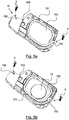
Fig. 1 depicts an assembled view of an electronic key for a motor vehicle, according to a non-limitative embodiment of the invention; -
Fig. 2 is a sectional view of the electronic key ofFig. 1 , said electronic key comprising a lower cover, an upper cover, a battery, an electronic printed card, one waterseal foam, and a battery cover, according to a first non-limitative embodiment; -
Fig. 3 is a sectional view of the electronic key ofFig. 1 , said electronic key comprising a lower cover, an upper cover, a battery, an electronic printed card, one waterseal foam, and a battery cover, according to a second non-limitative embodiment; -
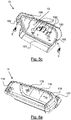
Fig. 4 depicts the different parts of said electronic device ofFig. 1 , said electronic key comprising a lower cover, an upper cover, a battery, an electronic printed card, two waterseal foams, and a battery cover, according to a third non-limitative embodiment; -
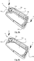
Fig. 5a is a bottom view of the lower cover of said electronic key ofFig. 1 to Fig. 4 , according to a non-limitative embodiment; -
Fig. 5b is a bottom view of the lower cover ofFig. 5a , with the battery, according to a non-limitative embodiment; -
Fig. 5c is a top view of the lower cover of said electronic key ofFig. 1 to Fig. 4 , according to a non-limitative embodiment; -
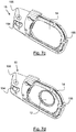
Fig. 6a is a top view of the upper cover of said electronic key ofFig. 1 to Fig. 4 , according to a non-limitative embodiment; -
Fig. 6b is a bottom view of the upper cover of said electronic key ofFig. 1 to Fig. 4 , according to a non-limitative embodiment; -
Fig. 6c is the bottom view of said upper cover ofFig. 6b with a waterseal foam, according to a non-limitative embodiment; -
Fig. 7a is a top view of the battery cover of said electronic key ofFig. 1 to Fig. 4 , according to a non-limitative embodiment; -
Fig. 7b is a bottom view of the battery cover of said electronic keyFig. 1 to Fig. 4 , according to a non-limitative embodiment; -
Fig. 7c is the bottom view of said battery cover ofFig. 7b with a waterseal foam, according to a non-limitative embodiment; -
Fig. 7d is the bottom view of said battery cover ofFig. 7c with the battery, according to a non-limitative embodiment. - In the following description, well-known functions or constructions by the man skilled in the art are not described in detail since they would obscure the invention in unnecessary detail.
- The present invention relates to an
electronic key 1 for avehicle 2. - In a non-limitative embodiment, said
vehicle 2 is a motor vehicle. - Such an
electronic key 1 is illustrated inFig.1 to Fig. 7d . - It comprises:
- a
lower cover 10; - an
upper cover 11; - a
battery 12; - an electronic printed
card 13 arranged between saidlower cover 10 and saidupper cover 11; - at least one
waterseal foam 14 arranged in theelectronic key 1 so that to obtain a watertightness of theelectronic key 1; - a
battery cover 15. - The different parts of said
electronic key 1 are further described hereinafter. - The
lower cover 10 is illustrated inFig. 2 to 4 , and5a to 5c . - In a non-limitative embodiment, it is made of a polymer material. In a non-limitative embodiment, it is made of plastic.
- As illustrated in
Fig. 5a and 5b , in a non-limitative embodiment, thelower cover 10 comprises ahousing 102 for thebattery 12. - As illustrated in
Fig. 5c , in a non-limitative embodiment, thelower cover 10 comprises ahousing 106 for the electronic printedcard 13. - As illustrated in
Fig. 5c , in a non-limitative embodiment, thelower cover 10 comprises aprimary rib 100 configured to compress the at least onewaterseal foam 14. In particular, it is configured to compress the at least onewaterseal foam 14 when this latter is arranged according to the first non-limitative embodiment, as illustrated inFig. 2 . - When the
lower cover 10 and theupper cover 11 are sealed together, theprimary rib 100 compresses thewaterseal foam 14 which is arranged within saidupper cover 11, as illustrated inFig. 2 or inFig. 6c . - In a non-limitative variant of embodiment, said
primary rib 100 is arranged on the inside perimeter of saidlower cover 10. In this cover, saidprimary rib 100 borders saidhousing 106 where part of thewaterseal foam 14 is driven into when compressed. Theprimary rib 100 compresses the perimeter of thewaterseal foam 14 which is arranged within saidupper cover 11. - As illustrated in
Fig. 5b , in a non-limitative embodiment, thelower cover 10 comprises asecondary rib 101 configured to compress the at least onewaterseal foam 14. In particular, it is configured to compress the at least onewaterseal foam 14 when this latter is arranged according to the second non-limitative embodiment, as illustrated inFig. 3 . - The
secondary rib 101 is on the opposite face of thelower cover 10, where theprimary rib 100 is. - Both
primary rib 100 andsecondary rib 101 belong to thelower cover 10. When thelower cover 10 and theupper cover 11 are sealed together, thesecondary rib 101 compresses thewaterseal foam 14 which is arranged within saidbattery cover 15, as illustrated inFig. 3 . - In a non-limitative variant of embodiment, said
secondary rib 101 is arranged on the inside perimeter of saidlower cover 10. In this cover, saidsecondary rib 101 borders saidhousing 102. Thesecondary rib 101 compresses the perimeter of thewaterseal foam 14 which is arranged within saidbattery cover 15. - In a non-limitative embodiment illustrated in
Fig. 5a to Fig. 5c , thelower cover 10 further comprises two sealingholes 105 configured to receive fixing means 3 in order to seal thelower cover 10 and theupper cover 11 together. The pressure applied by the fixing means 3 enable thewaterseal foam 14 to be compressed by theprimary rib 100 in order to obtain the watertightness of theelectronic key 1. In a non-limitative example, the fixing means 3 are some screws. - In a non-limitative embodiment illustrated in
Fig. 5a and Fig. 5b , thelower cover 10 further comprises ahole 104 for a push button (not illustrated) to be inserted. In a non-limitative embodiment illustrated inFig. 5c , thelower cover 10 further comprises afirst part 103 of a cover for a key bit (not illustrated) of theelectronic key 1 to be inserted in. As well-known by the man skilled in the art, the push button enables the key bit to come out of the cover when a user of thevehicle 2 wants to manually unlock thevehicle 2. - The
upper cover 11 is illustrated inFig. 1, to 4 ,6 and7 . - In a non-limitative embodiment, it is made of a polymer material. In a non-limitative embodiment, it is made of plastic.
- The
upper cover 11 comprises aframe 117. In a non-limitative embodiment, it is made of hard plastic. - In a non-limitative embodiment illustrated in
Fig. 6a , theupper cover 11 comprises a plurality ofbuttons 116 framed by saidframe 117. Thebuttons 116 permits to run different functions, such as some lock and unlock functions to lock/unlock some openings (doors, trunk etc.) of thevehicle 2. In the non-limitative illustrated example, abutton 116 is used for a lock function, another one for an unlock function, and a last one for any other function such as a wire pressure diagnostic function. - The plurality of
buttons 116 are each associated to a switch button (not-illustrated) which is connected to the electronic printedcard 13. - In a non-limitative embodiment, the plurality of
buttons 116 are separated buttons. They are composed of the same material than theframe 117. - In a non-limitative embodiment, the plurality of
buttons 116 are integrated buttons. They are over-molded and their material is softer than theframe 117. - In a non-limitative embodiment illustrated in
Fig. 6a , theupper cover 11 further comprises ahole 114 for the push button (not illustrated) to be inserted. - In a non-limitative embodiment illustrated in
Fig. 6b , theupper cover 11 further comprises a primary rib 110 configured to compress said at least onewaterseal foam 14. - In a non-limitative embodiment, it comprises a
housing 111 for awaterseal foam 14. As illustrated inFig. 6c , in a non-limitative embodiment, thewaterseal foam 14 is arranged within saidupper cover 11. - In a non-limitative embodiment, the
upper cover 11 further comprises anedge 115 on the perimeter of saidhousing 111. When thelower cover 10 and theupper cover 11 are sealed together, the perimeter of thewaterseal foam 14 will be compressed between saidedge 115 and theprimary rib 100 of thelower cover 10, as illustrated inFig. 2 orFig. 4 . - In a non-limitative embodiment, said
waterseal foam 14 is fixed to saidupper cover 11 with a watertight adhesive or some watertight glue. - A pressure is applied on said
lower cover 10 andupper cover 11 for the sealing. The pressure is applied via a gripping force. In a non-limitative embodiment, said gripping force is exerted via the fixing means 3. - The fixing means 3 are adapted to assemble all the components of the
electronic key 1 together. Hence, in the non-limitative example of thescrews 3, saidscrews 3 are adapted to go through saidlower cover 10, saidupper cover 11 and saidupper cover 15. - In a non-limitative embodiment illustrated in
Fig. 6b and Fig. 6c , theupper cover 11 further comprises two protrudingthread 112 configured to receive two fixing means 3 in order to seal thelower cover 10 and theupper cover 11 together. Each protrudingthread 12 is configured to be positioned in front of eachhole 105 of saidlower cover 10. - In a non-limitative embodiment illustrated in
Fig. 6b and Fig. 6c , theupper cover 11 further comprises asecond part 113 of a cover for a key bit (not illustrated) of theelectronic key 1 to be inserted in and ahole 114 for the push button (not illustrated) to be inserted. - The
battery 12 is illustrated inFig. 2 to 4 , and7d . - The
battery 12 is arranged between saidlower cover 10 and saidbattery cover 15. - In a non-limitative embodiment illustrated in
Fig. 5b , it is arranged within thelower cover 10. - The
battery 12 is connected to the electronic printedcard 13 so as to power supply said electronic printedcard 13. Thebattery 12 comprisescontacts 120 to make electrical contact with the electronic printedcard 13. - The
battery 12 is configured to be housed in thehousing 102 of thelower cover 10 as illustrated inFig. 5b . - In the second and third non-limitative embodiments of the
electronic key 1, thebattery 12 is arranged between saidlower cover 10 and saidwaterseal foam 14 as illustrated inFig. 3 (second embodiment) orFig. 4 (third embodiment). - When the
lower cover 10 and theupper cover 11 are sealed, thewaterseal foam 14 is compressed onto thebattery 12. - The electronic printed
card 13 is illustrated inFig. 2, to 4 and5c . - In a non-limitative embodiment, the electronic printed
card 13 is sandwiched between saidlower cover 10 and saidupper cover 11. - In a non-limitative embodiment, the electronic printed
card 13 is arranged within thelower cover 10. In particular, it is arranged in thehousing 106 of saidlower cover 10 as illustrated inFig. 5c . - The electronic printed
card 13 comprises two faces which are opposed, one face faces thebattery 12 and one face faces thehousing 111 of saidupper cover 11. - In a non-limitative embodiment, said electronic printed
card 13 is a printed circuit board assembly PCBA, also called PCBA card. - In a non-limitative embodiment, the electronic printed
card 13 comprises a plurality ofelectronic components 130. In non-limitative embodiments, said plurality ofelectronic components 130 are disposed on one face, or on the two faces. Saidplurality components 130 comprise the switch buttons connected to thebuttons 116 so as to enable the functions, such a lock and unlock to be performed. - The at least one
Waterseal foam 14 is illustrated inFig. 2 to 4 ,6b ,7c and 7d . The at least onewaterseal foam 14 is a soft material which adapts to the plastic deformation when thelower cover 10 and theupper cover 11 are sealed together. - The at least one
waterseal foam 14 is arranged in theelectronic key 1 so that to obtain a watertightness of theelectronic key 1. It is arranged in theelectronic key 1 according to three non-limitative embodiments. - It is to be noted that when it is compressed up to 10%, the at least one
waterseal foam 14 permits to achieve the watertightness of theelectronic key 1. - In a non-limitative embodiment, said
waterseal foam 14 has a ring shape, or a frame shape. - In a non-limitative example, for a 33% compression pressure of 63kPa (Pascal), a force of 17,9 N (Newton) may be applied on a frame
shape waterseal foam 14 which is of 284mm2. This force is sufficient to obtain the watertightness of theelectronic key 1. - In a non-limitative example, for a 33% compression pressure of 63kPa (Pascal), a force of 1,78 N (Newton) may be applied on a ring
shape waterseal foam 14 which is of 28,26mm2. This force is sufficient to obtain the watertightness of theelectronic key 1. - In a first non-limitative embodiment illustrated in
Fig. 2 andFig. 6c , theelectronic key 1 comprises onewaterseal foam 14 arranged between saidupper cover 11 and said electronic printedcard 13. In a non-limitative variant of embodiment illustrated inFig. 6c , thewaterseal foam 14 is arranged within saidupper cover 11, in particular in thehousing 111 of saidupper cover 11. Saidwaterseal foam 14 is also calledprimary waterseal foam 14. - In a first non-limitative variant of embodiment, said
waterseal foam 14 is fixed to saidupper cover 11 with a watertight adhesive or some watertight glue. Hence, thewaterseal foam 14 comprises an adhesive on one side, or is glued on one side. On the other side, theprimary rib 100 of thelower cover 10 compressed saidwaterseal foam 14 on saidedge 115 of saidupper cover 11. Hence, thewaterseal foam 14 is compressed around the PCBA card so that no water damages said PCBA card. - When the
lower cover 10 comprises noprimary rib 100, in a second non-limitative variant of embodiment, saidwaterseal foam 14 is fixed to saidupper cover 11 and to said electronic printedcard 13 with a watertight adhesive or some watertight glue. Hence, thewaterseal foam 14 comprises an adhesive on two sides, or is glued on two sides. Hence, when thelower cover 10 and theupper cover 11 are assembled together by means of the fixing means 3, the pressure applied enables thewaterseal foam 14 to be well fixed and well maintained between theupper cover 11 and said electronic printedcard 13. - In a non-limitative embodiment, said
waterseal foam 14 has a ring shape, or a frame shape which extends within thehousing 111 of saidupper cover 11. The ring shape permits to have a hole wherein the PCBA card may be integrated. The frame shape is illustrated inFig. 6c . It permits to cover the whole PCBA card. When thelower cover 10 and theupper cover 11 are assembled together by means of the fixing means 3, part of thewaterseal foam 14 goes into thehousing 106 of saidlower cover 10. - In a second non-limitative embodiment illustrated in
Fig. 3 andFig. 7c and Fig. 7d , theelectronic key 1 comprises onewaterseal foam 14 arranged between saidbattery 12 and saidbattery cover 15. In a non-limitative variant of embodiment illustrated inFig. 7c and inFig. 7d , thewaterseal foam 14 is arranged within saidbattery cover 15. - Said
waterseal foam 14 is also calledsecondary waterseal foam 14. - In a first non-limitative variant of embodiment, said
waterseal foam 14 is fixed to saidbattery cover 15 with a watertight adhesive or some watertight glue. Hence, thewaterseal foam 14 comprises an adhesive on one side, or is glued on one side. On the other side, thesecondary rib 101 of thelower cover 10 compressed saidwaterseal foam 14 within saidbattery cover 15. - When the
lower cover 10 comprises nosecondary rib 101, in a second non-limitative variant of embodiment, saidwaterseal foam 14 is fixed to saidbattery cover 15 and to saidbattery 12 with a watertight adhesive or some watertight glue. Hence, when thelower cover 10 and theupper cover 11 are assembled together by means of the fixing means 3, the pressure applied enables thewaterseal foam 14 to be well fixed and well maintained between thebattery cover 15 and saidbattery 12. - In a non-limitative embodiment, said
waterseal foam 14 has a ring shape, or a frame shape which extends within thehousing 151 of saidbattery cover 15. The ring shape permits to have a hole wherein thebattery 12 may be integrated. The frame shape is illustrated inFig. 7c and 7d . It permits to cover thewhole battery 12. When thelower cover 10 and theupper cover 11 are assembled together by means of the fixing means 3, part of thewaterseal foam 14 goes into thehousing 102 of saidlower cover 10. - In a third non-limitative embodiment illustrated in
Fig. 4 , the first non-limitative embodiment and the second non-limitative embodiment are combined. Hence, theelectronic key 1 comprises: - one
waterseal foam 14 arranged between saidupper cover 11 and said electronic printedcard 13; and - one
waterseal foam 14 arranged between saidbattery 12 and saidbattery cover 15. - The
battery cover 15 is illustrated inFig. 2, to 4 , and7a to 7d . - In a non-limitative embodiment, it is made of a polymer material. In a non-limitative embodiment, it is made of plastic.
- The
battery cover 15 enables to close theelectronic key 1. Oneside 150 illustrated inFig. 7a is accessible by the user of thevehicle 2. - It is arranged to be fixed on the
lower cover 10. - In a non-limitative embodiment, it comprises two
holes 155 which are configured to receive the fixing means 3 in order to seal thelower cover 10 and thebattery cover 15 together. - It is to be reminded that the same fixing means 3 enable to fix the
lower cover 10, thebattery cover 15 and theupper cover 11 together. - In a non-limitative embodiment, the
battery cover 15 further comprises ahole 154 for the push button (not illustrated) to be inserted. - In a non-limitative embodiment illustrated in
Fig. 7b , thebattery cover 15 further comprises ahousing 151 for awaterseal foam 14, as illustrated inFig. 7c and 7d . - The
battery 12 is in contact with saidwaterseal foam 14 as illustrated inFig. 7d . - It is to be understood that the present invention is not limited to the aforementioned embodiments and variations and modifications may be made without departing from the scope of the invention. In the respect, the following remarks are made.
- It is to be understood that the present invention is not limited to the aforementioned embodiments.
- Hence, in a non-limitative embodiment, the
waterseal foam 14 may be combined with a silicon membrane. In a non-limitative variant of said embodiment, the silicon membrane may be used between thelower cover 10 and theupper cover 11 for the electronic printedcard 13, and thewaterseal foam 14 for thebattery 12, or vice versa. - Hence, some embodiments of the invention may comprise one or a plurality of the following advantages:
- it permits to reduce the force used to seal
lower cover 10 and theupper cover 11 together which leads to less plastic deformation than the solution of the prior art or a solution with only over-molded soft plastic parts compression of theelectronic key 1. Hence there will be less counterforce on the plastic parts of theelectronic key 1 and the compression will be more efficient and thus the watertighness more robust; - it permits to increase the watertightness of the
electronic key 1 with thewaterseal foam 14 as there is less plastic deformation; - it permits to decrease the volume of the plastic used for the
electronic key 1, because less counterforce will be on the plastic compared with a silicon membrane. Therefore the plastic volume can be optimized and with a reduced volume of theelectronic key 1, one can make the same function; - it significantly reduces the cost of the
electronic key 1 as the foam is t significantly cheaper than the silicon membrane ; - it permits the
electronic key 1 to be more robust to resist to watertightness because the plastic parts will have less deformation during standard thermal shock test; - as the
waterseal foam 14 is softer then a silicon membrane, it permits to have more space for the electronic components of the card PCBA or for thebattery 12. - Any reference sign in the following claims should not be construed as limiting the claim. It will be obvious that the verb "to comprise" and its conjugations do not exclude the presence of any other steps or components beside those defined in any claim. The word "a" or "an" preceding an component or step does not exclude the presence of a plurality of such components or steps.
Claims (14)
- Electronic key (1) for a vehicle (2), comprising:- a lower cover (10);- an upper cover (11);- a battery (12);- an electronic printed card (13) arranged between said lower cover (10) and said upper cover (11);Wherein said electronic key (1) further comprises:- at least one waterseal foam (14) arranged in the electronic key (1) so that to obtain a watertightness of the electronic key (1);- a battery cover (15).
- Electronic key (1) according to claim 1, wherein said electronic key (1) comprises one waterseal foam (14) arranged between said upper cover (11) and said electronic printed card (13).
- Electronic key (1) according to claim 2, wherein said waterseal foam (14) is arranged within said upper cover (11).
- Electronic key (1) according to claim 2 or claim 3, wherein said lower cover (10) comprises a primary rib (100) configured to compress said waterseal foam (14).
- Electronic key (1) according to any one of the previous claims 2 to 4, wherein said waterseal foam (14) is fixed to said upper cover (11) with a watertight adhesive or some watertight glue.
- Electronic key (1) according to the previous claim 2 or claim 3, wherein said waterseal foam (14) is fixed to said upper cover (11) and to said electronic printed card (13) with a watertight adhesive or some watertight glue.
- Electronic key (1) according to any one of the previous claims 2 to 6, wherein said waterseal foam (14) has a ring shape, or a frame shape which extends within a housing (111) of said upper cover (11).
- Electronic key (1) according to any one of the previous claims 1 to 7, wherein said electronic key (1) comprises one waterseal foam (14) arranged between said battery (12) and said battery cover (15).
- Electronic key (1) according to claim 8, wherein said waterseal foam (14) is arranged within said battery cover (15).
- Electronic key (1) according to claim 8 or claim 9, wherein said lower cover (10) comprises a secondary rib (101) configured to compress said waterseal foam (14).
- Electronic key (1) according to any one of the previous claims 8 to 10, wherein said waterseal foam (14) is fixed to said battery cover (15) with a watertight adhesive or some watertight glue.
- Electronic key (1) according to claim 8 or claim 9, wherein said waterseal foam (14) is fixed to said battery cover (15) and to said battery (13) with a watertight adhesive or some watertight glue.
- Electronic key (1) according to any one of the previous claims 8 to 12, wherein said waterseal foam (14) has a ring shape, or a frame shape which extends within a housing (151) of said battery cover (15).
- Electronic key (1) according to any one of the previous claims 1 to 13, wherein the battery (12) is arranged within said lower cover (10).
Priority Applications (1)
| Application Number | Priority Date | Filing Date | Title |
|---|---|---|---|
| EP18210626.0A EP3664045A1 (en) | 2018-12-06 | 2018-12-06 | Electronic key for a vehicle with a waterseal foam |
Applications Claiming Priority (1)
| Application Number | Priority Date | Filing Date | Title |
|---|---|---|---|
| EP18210626.0A EP3664045A1 (en) | 2018-12-06 | 2018-12-06 | Electronic key for a vehicle with a waterseal foam |
Publications (1)
| Publication Number | Publication Date |
|---|---|
| EP3664045A1 true EP3664045A1 (en) | 2020-06-10 |
Family
ID=64650195
Family Applications (1)
| Application Number | Title | Priority Date | Filing Date |
|---|---|---|---|
| EP18210626.0A Pending EP3664045A1 (en) | 2018-12-06 | 2018-12-06 | Electronic key for a vehicle with a waterseal foam |
Country Status (1)
| Country | Link |
|---|---|
| EP (1) | EP3664045A1 (en) |
Citations (2)
| Publication number | Priority date | Publication date | Assignee | Title |
|---|---|---|---|---|
| WO2012013419A1 (en) * | 2010-07-26 | 2012-02-02 | Tesa Se | Adhesive seal |
| CN202401838U (en) * | 2011-12-30 | 2012-08-29 | 苏州新昌科技有限公司 | Water-proof motor vehicle key |
-
2018
- 2018-12-06 EP EP18210626.0A patent/EP3664045A1/en active Pending
Patent Citations (2)
| Publication number | Priority date | Publication date | Assignee | Title |
|---|---|---|---|---|
| WO2012013419A1 (en) * | 2010-07-26 | 2012-02-02 | Tesa Se | Adhesive seal |
| CN202401838U (en) * | 2011-12-30 | 2012-08-29 | 苏州新昌科技有限公司 | Water-proof motor vehicle key |
Similar Documents
| Publication | Publication Date | Title |
|---|---|---|
| US9839151B2 (en) | Electronic device having a waterproof structure | |
| AU2014201514B2 (en) | Waterproof ear jack socket and method of manufacturing the same | |
| TWI576878B (en) | Electronic device with water tight button assembly and method of assembling the same | |
| KR101186608B1 (en) | Mobile communication device | |
| WO2015182049A1 (en) | Waterproof connection apparatus for electronic equipment, and electronic equipment | |
| US7864513B2 (en) | Keypad module for mobile electronic device | |
| TWI576036B (en) | Mobile terminal housing | |
| US8361643B2 (en) | Battery cover latch mechanism and portable electronic device using same | |
| JP4182430B2 (en) | Transmitter | |
| US20100035136A1 (en) | Battery fixing apparatus and electronic device using the same | |
| US20090260202A1 (en) | Battery cover latch assembly | |
| CN111668051A (en) | Key module and electronic equipment | |
| EP3664045A1 (en) | Electronic key for a vehicle with a waterseal foam | |
| JP2006516208A (en) | Disposable defibrillator electrode assembly | |
| US10062985B2 (en) | Connector module and portable electronic device | |
| CN110995897A (en) | Electronic device | |
| WO2007075881A2 (en) | Waterproof remote control | |
| WO2022262466A1 (en) | Waterproof member and waterproof button module for side fingerprint button, and terminal | |
| KR101613972B1 (en) | Electronic device with waterproof structure | |
| CN219960994U (en) | Electronic equipment | |
| CN211128654U (en) | Waterproof structure of electronic device | |
| CN219873246U (en) | Waterproof substrate structure, waterproof key mechanism and electronic product | |
| CN220420472U (en) | Waterproof button structure of bone conduction earphone and bone conduction earphone | |
| KR102142572B1 (en) | Electronic device | |
| JP2009289639A (en) | Waterproof button switch |
Legal Events
| Date | Code | Title | Description |
|---|---|---|---|
| PUAI | Public reference made under article 153(3) epc to a published international application that has entered the european phase |
Free format text: ORIGINAL CODE: 0009012 |
|
| STAA | Information on the status of an ep patent application or granted ep patent |
Free format text: STATUS: THE APPLICATION HAS BEEN PUBLISHED |
|
| AK | Designated contracting states |
Kind code of ref document: A1 Designated state(s): AL AT BE BG CH CY CZ DE DK EE ES FI FR GB GR HR HU IE IS IT LI LT LU LV MC MK MT NL NO PL PT RO RS SE SI SK SM TR |
|
| AX | Request for extension of the european patent |
Extension state: BA ME |
|
| STAA | Information on the status of an ep patent application or granted ep patent |
Free format text: STATUS: REQUEST FOR EXAMINATION WAS MADE |
|
| 17P | Request for examination filed |
Effective date: 20201203 |
|
| RBV | Designated contracting states (corrected) |
Designated state(s): AL AT BE BG CH CY CZ DE DK EE ES FI FR GB GR HR HU IE IS IT LI LT LU LV MC MK MT NL NO PL PT RO RS SE SI SK SM TR |
|
| STAA | Information on the status of an ep patent application or granted ep patent |
Free format text: STATUS: EXAMINATION IS IN PROGRESS |
|
| 17Q | First examination report despatched |
Effective date: 20221214 |
|
| RAP3 | Party data changed (applicant data changed or rights of an application transferred) |
Owner name: VALEO COMFORT AND DRIVING ASSISTANCE |
|
| P01 | Opt-out of the competence of the unified patent court (upc) registered |
Effective date: 20230528 |
|
| RAP3 | Party data changed (applicant data changed or rights of an application transferred) |
Owner name: VALEO COMFORT AND DRIVING ASSISTANCE |