EP3663998A1 - Crew alerting systems and methods for mobile platforms - Google Patents
Crew alerting systems and methods for mobile platforms Download PDFInfo
- Publication number
- EP3663998A1 EP3663998A1 EP19212757.9A EP19212757A EP3663998A1 EP 3663998 A1 EP3663998 A1 EP 3663998A1 EP 19212757 A EP19212757 A EP 19212757A EP 3663998 A1 EP3663998 A1 EP 3663998A1
- Authority
- EP
- European Patent Office
- Prior art keywords
- indication
- crew
- mobile platform
- display area
- aircraft
- Prior art date
- Legal status (The legal status is an assumption and is not a legal conclusion. Google has not performed a legal analysis and makes no representation as to the accuracy of the status listed.)
- Pending
Links
Images


Classifications
-
- G—PHYSICS
- G06—COMPUTING; CALCULATING OR COUNTING
- G06Q—INFORMATION AND COMMUNICATION TECHNOLOGY [ICT] SPECIALLY ADAPTED FOR ADMINISTRATIVE, COMMERCIAL, FINANCIAL, MANAGERIAL OR SUPERVISORY PURPOSES; SYSTEMS OR METHODS SPECIALLY ADAPTED FOR ADMINISTRATIVE, COMMERCIAL, FINANCIAL, MANAGERIAL OR SUPERVISORY PURPOSES, NOT OTHERWISE PROVIDED FOR
- G06Q10/00—Administration; Management
- G06Q10/06—Resources, workflows, human or project management; Enterprise or organisation planning; Enterprise or organisation modelling
-
- G—PHYSICS
- G08—SIGNALLING
- G08G—TRAFFIC CONTROL SYSTEMS
- G08G5/00—Traffic control systems for aircraft, e.g. air-traffic control [ATC]
- G08G5/0017—Arrangements for implementing traffic-related aircraft activities, e.g. arrangements for generating, displaying, acquiring or managing traffic information
- G08G5/0021—Arrangements for implementing traffic-related aircraft activities, e.g. arrangements for generating, displaying, acquiring or managing traffic information located in the aircraft
-
- B—PERFORMING OPERATIONS; TRANSPORTING
- B64—AIRCRAFT; AVIATION; COSMONAUTICS
- B64D—EQUIPMENT FOR FITTING IN OR TO AIRCRAFT; FLIGHT SUITS; PARACHUTES; ARRANGEMENTS OR MOUNTING OF POWER PLANTS OR PROPULSION TRANSMISSIONS IN AIRCRAFT
- B64D45/00—Aircraft indicators or protectors not otherwise provided for
-
- G—PHYSICS
- G01—MEASURING; TESTING
- G01C—MEASURING DISTANCES, LEVELS OR BEARINGS; SURVEYING; NAVIGATION; GYROSCOPIC INSTRUMENTS; PHOTOGRAMMETRY OR VIDEOGRAMMETRY
- G01C23/00—Combined instruments indicating more than one navigational value, e.g. for aircraft; Combined measuring devices for measuring two or more variables of movement, e.g. distance, speed or acceleration
- G01C23/005—Flight directors
-
- G—PHYSICS
- G08—SIGNALLING
- G08G—TRAFFIC CONTROL SYSTEMS
- G08G5/00—Traffic control systems for aircraft, e.g. air-traffic control [ATC]
- G08G5/0004—Transmission of traffic-related information to or from an aircraft
- G08G5/0013—Transmission of traffic-related information to or from an aircraft with a ground station
-
- G—PHYSICS
- G08—SIGNALLING
- G08G—TRAFFIC CONTROL SYSTEMS
- G08G5/00—Traffic control systems for aircraft, e.g. air-traffic control [ATC]
- G08G5/0047—Navigation or guidance aids for a single aircraft
- G08G5/0052—Navigation or guidance aids for a single aircraft for cruising
-
- G—PHYSICS
- G08—SIGNALLING
- G08G—TRAFFIC CONTROL SYSTEMS
- G08G5/00—Traffic control systems for aircraft, e.g. air-traffic control [ATC]
- G08G5/0073—Surveillance aids
- G08G5/0078—Surveillance aids for monitoring traffic from the aircraft
-
- G—PHYSICS
- G08—SIGNALLING
- G08G—TRAFFIC CONTROL SYSTEMS
- G08G5/00—Traffic control systems for aircraft, e.g. air-traffic control [ATC]
- G08G5/0073—Surveillance aids
- G08G5/0091—Surveillance aids for monitoring atmospheric conditions
-
- G—PHYSICS
- G08—SIGNALLING
- G08G—TRAFFIC CONTROL SYSTEMS
- G08G5/00—Traffic control systems for aircraft, e.g. air-traffic control [ATC]
- G08G5/02—Automatic approach or landing aids, i.e. systems in which flight data of incoming planes are processed to provide landing data
- G08G5/025—Navigation or guidance aids
-
- B—PERFORMING OPERATIONS; TRANSPORTING
- B64—AIRCRAFT; AVIATION; COSMONAUTICS
- B64D—EQUIPMENT FOR FITTING IN OR TO AIRCRAFT; FLIGHT SUITS; PARACHUTES; ARRANGEMENTS OR MOUNTING OF POWER PLANTS OR PROPULSION TRANSMISSIONS IN AIRCRAFT
- B64D45/00—Aircraft indicators or protectors not otherwise provided for
- B64D2045/0085—Devices for aircraft health monitoring, e.g. monitoring flutter or vibration
-
- B—PERFORMING OPERATIONS; TRANSPORTING
- B64—AIRCRAFT; AVIATION; COSMONAUTICS
- B64D—EQUIPMENT FOR FITTING IN OR TO AIRCRAFT; FLIGHT SUITS; PARACHUTES; ARRANGEMENTS OR MOUNTING OF POWER PLANTS OR PROPULSION TRANSMISSIONS IN AIRCRAFT
- B64D43/00—Arrangements or adaptations of instruments
Definitions
- Aircraft are typically equipped with a crew alerting system (CAS) to provide the flight crew with annunciations associated with various aircraft systems.
- CAS crew alerting system
- the combination of engine indications and such crew alerting system is commonly known as an engine indication and crew alerting system (EICAS).
- EICAS engine indication and crew alerting system
- a crew alerting system for a mobile platform, the system comprising: a display device defining a display area; one or more data processors operatively coupled to the display device; and non-transitory machine-readable memory operatively coupled to the one or more data processors and storing instructions executable by the one or more processors.
- the instructions may be configured to cause the one or more processors to, upon receiving notification of an occurrence of a manual system configuration associated with the mobile platform, generate a first output for causing the display device to display a first indication in the display area.
- the first indication may comprise a first textual message.
- the instructions may be configured to cause the one or more processors to, upon receiving notification of an occurrence of an automated system configuration associated with the mobile platform, generate a second output for causing the display device to display a second indication in the display area.
- the second indication may comprise a second textual message accompanied by a supplemental indication.
- the first and second textual messages are of a same color.
- the first and second textual messages are white.
- the supplemental indication is disposed on a same line as the second textual message.
- the supplemental indication is disposed in front of the second textual message.
- the supplemental indication has a different color than the second textual message.
- the supplemental indication is adjacent to the second textual message.
- the manual system configuration and the automated system configuration are associated with a same system of the aircraft.
- the manual system configuration and the automated system configuration perform equivalent actions on the system of the aircraft.
- an aircraft comprising a crew alerting system as described herein.
- a crew alerting system for a mobile platform, the system comprising: a display device defining a display area; one or more data processors operatively coupled to the display device; and non-transitory machine-readable memory operatively coupled to the one or more data processors and storing instructions executable by the one or more processors and configured to cause the one or more processors to: upon receiving notification of an occurrence of an automated system configuration associated with the mobile platform, generate an output for causing the display device to display an indication in the display area, the indication comprising a textual message in a color associated with a status message accompanied by a graphical indication in a color associated with an advisory alert.
- a method for alerting a crew of a mobile platform of a system configuration associated with the mobile platform using a display area of a crew alerting system of the mobile platform comprising: upon receiving notification of an occurrence of a manual system configuration associated with the mobile platform, displaying a first indication in the display area of the crew alerting system of the mobile platform, the first indication comprising a first textual message; and upon receiving notification of an occurrence of an automated system configuration associated with the mobile platform, displaying a second indication in the display area of the crew alerting system of the mobile platform, the second indication comprising a second textual message accompanied by a supplemental indication.
- the first and second textual messages are of a same color.
- the first and second textual messages are white.
- the first and second textual messages comprise a same content.
- the supplemental indication is disposed on the same line as the second textual message.
- the supplemental indication is disposed in front of the second textual message.
- the supplemental indication has a different color than the second textual message.
- the supplemental indication is adjacent the second textual message.
- the manual system configuration and the automated system configuration are associated with a same system of the aircraft.
- the manual system configuration and the automated system configuration perform equivalent actions on the system of the aircraft.
- the present disclosure describes systems, display devices and methods associated with crew alerting systems of aircraft and other mobile platforms. Even though various aspects of the present disclosure are described in the context of aircraft, it is understood that aspects disclosed herein are equally applicable to centralized alerting systems for other systems and mobile platforms (e.g., vehicles) such as trains, ships and busses for example.
- the systems, display devices and methods disclosed herein may be considered to provide crew alerting systems of improved functionality compared to conventional crew alerting systems by providing awareness-enhancing indications while being mindful of the limited real estate available on an aircraft flight deck.
- Flight deck 12 may comprise left portion 12A intended to be used by a pilot (sometimes referred to as “captain”) of aircraft 10 and right portion 12B intended to be used by a co-pilot (sometimes referred to as "first officer") of aircraft 10.
- Left portion 12A and right portion 12B may comprise functionally identical components so that at least some operational redundancy may be provided between left portion 12A and right portion 12B of flight deck 12.
- the term "flight crew” is intended to encompass one or more individuals responsible for the operation of aircraft 10 during flight. Such individuals may, for example, include the pilot and/or the co-pilot.
- the term “crew” is intended to encompass one or more individuals responsible for or associated with the operation of a mobile platform comprising a crew alerting system as disclosed herein.
- Flight deck 12 may comprise one or more display devices 14 providing respective display areas 16.
- left portion 12A and right portion 12B may each comprise two display devices 14 and an additional display device 14 may be provided in pedestal region 18 of flight deck 12.
- Display device 14 provided in pedestal region 18 may be shared between the pilot and the co-pilot during normal operation of aircraft 10.
- Display devices 14 may include one or more cathode-ray tubes (CRTs), liquid crystal displays (LCDs), plasma displays, light-emitting diode (LED) based displays, organic light-emitting diode (OLED) based displays, or any known or other type of display device that may be suitable for use in flight deck 12.
- CTRs cathode-ray tubes
- LCDs liquid crystal displays
- plasma displays plasma displays
- LED light-emitting diode
- OLED organic light-emitting diode
- Display devices 14 may be configured to dynamically display operational and status information about various systems of aircraft 10, information related to flight/mission planning, maps and any other information that may be useful for the flight crew (e.g., pilot(s)) during the operation of aircraft 10. Display devices 14 may facilitate dialog between the flight crew and various systems of aircraft 10 via suitable graphical user interfaces.
- Flight deck 12 may comprise one or more data input devices such as, for example, one or more cursor control devices 20, one or more multi-function keypads 22 and one or more (e.g., standalone or multifunction) controllers 23 that may permit data entry by the flight crew.
- controller(s) 23 may be disposed in the glare shield above one or more display devices 14.
- One or more of display devices 14 may comprise CAS display area 16A dedicated to centralized crew alerting system 24 shown schematically in FIG. 2 and referred hereinafter as "CAS 24", during one or more phases of operation of aircraft 10.
- CAS 24 centralized crew alerting system 24 shown schematically in FIG. 2 and referred hereinafter as "CAS 24"
- a single instance of CAS display area 16A may be displayed on a display device 14 that is conveniently located to be visible by both the pilot and the co-pilot.
- more than one instance of CAS display area 16A may be displayed on more than one respective display device 14.
- the display device 14 on which CAS display area 16A is provided may also include engine indications and therefore CAS display area 16A may be part of an engine indication and crew alerting system (EICAS).
- EICAS engine indication and crew alerting system
- CAS display area 16A may be selectively displayed on one or more display devices 14 of flight deck 12 based on input from the flight crew.
- CAS display area 16A and the display of its contents is not limited to one or more display devices 14 onboard aircraft 10.
- CAS display area 16A could, alternatively or in addition, be provided on a display device that is off of aircraft 10.
- CAS display area 16A could be provided on a display device of a ground station to alert a ground-based operator of aircraft 10 or support (e.g., maintenance) personnel.
- relevant information could be transmitted from aircraft 10 to a location remote from aircraft 10 (e.g., ground station) in order to alert an individual at such location in accordance with aspects of the present disclosure.
- FIG. 2 shows a schematic representation of an example CAS 24 which may be part of aircraft 10.
- CAS 24 may be integrated with flight deck 12.
- CAS 24 may comprise one or more computers 26 (referred hereinafter in the singular) operatively coupled to one or more display devices 14 (referred hereinafter in the singular) of flight deck 12.
- Computer 26 may comprise one or more data processors 28 (referred hereinafter in the singular) and one or more computer-readable memories 30 (referred hereinafter in the singular) storing machine-readable instructions 32 executable by data processor 28 and configured to cause data processor 28 to generate one or more outputs 34 (referred hereinafter in the singular).
- Output 34 may comprise one or more signals for causing display device 14 of aircraft 10 to display CAS display area 16A and its contents.
- Computer 26 may receive input(s) 36 in the form of data or information that may be processed by data processor 28 based on instructions 32 in order to generate output 34.
- input 36 may comprise information (data) indicative of a configuration or reconfiguration associated with one or more systems 38 of aircraft 10.
- Systems 38 of aircraft 10 may include, for example, a hydraulic system, an electrical system, a fuel system, flight control surfaces, a navigation system, an engine and/or any other aircraft systems.
- control system 50 may comprise one or more computers, for example, similar to computer 26 as described herein.
- control system 50 may be a part of computer 26.
- an automated configuration of a system 38 may be caused by control system 50, in an example, without any manual input from the flight crew.
- Control system 50 can be considered part of an avionics suite of aircraft 10.
- control system 50 can be configured to carry out additional functions than those described herein.
- control system 50 can be of the type known as a flight control computer (FCC) of aircraft 10.
- control system 50 can include a fly-by-wire control system of aircraft 10.
- One or more systems 38 of aircraft 10 may also be controlled or actuated by the flight crew directly accessing a system 38, for example, to configure or reconfigure a system 38 or various parameters of a system 38.
- the flight crew may also control one or more systems 38 by way of manual input to control system 50.
- a manual configuration of a system 38 may be caused by a manual action performed by the flight crew.
- the same change to system 38 results from either a manual system configuration or an automated system configuration.
- a manual system configuration and an automated system configuration may perform equivalent actions on a system 38 of the aircraft.
- input 36 may alternatively or in addition comprise information (data) indicative of, or notification of, occurrence of a configuration associated with one or more systems 38 of aircraft 10 and whether the configuration associated with one or more systems 38 of aircraft 10 was an automated configuration or a manual configuration.
- configuration changes could include: a switch from a magnetic heading to a true heading or vice versa in a navigation system, an activation or deactivation of a hydraulic pump, a change in position of a flight control surface, discharge of a fire extinguishing bottle, and opening or closing of a bleed air system valve.
- input(s) 36 may include or be indicative of sensed signals acquired via one or more (e.g., pressure, position, acceleration, temperature or other) sensors 40 associated with one or more aircraft systems 38. Accordingly, input(s) 36 may comprise one or more sensed parameters indicative of one or more states or configurations of aircraft system(s) 38.
- computer 26 may, based on input(s) 36, generate output 34 for causing display device 14 to display one or more combined advisory and status indications as described below and associated with a configuration of a system 38 of aircraft 10 in CAS display area 16A.
- Computer 26 may be part of an avionics suite of aircraft 10. For example, in some embodiments, computer 26 may carry out additional functions than those described herein including the management of one or more graphic user interfaces of flight deck 12 and/or other part(s) of aircraft 10. In various embodiments, computer 26 may comprise more than one computer or data processor where the methods disclosed herein (or part(s) thereof) could be performed using a plurality of computers or data processors, or, alternatively, be performed entirely using a single computer or data processor. In some embodiments, computer 26 could be physically integrated with (e.g., embedded in) display device 14.
- Data processor 28 may comprise any suitable device(s) configured to cause a series of steps to be performed by computer 26 so as to implement a computer-implemented process such that instructions 32, when executed by computer 26 or other programmable apparatus, may cause the functions/acts specified in the methods described herein to be executed.
- Memory 30 may comprise any suitable known or other machine-readable storage medium.
- Memory 30 may comprise non-transitory computer readable storage medium.
- Memory 30 may comprise any storage means (e.g. devices) suitable for retrievably storing machine-readable instructions 32 executable by data processor 28.
- aspects of the present disclosure may be embodied as systems, devices, methods and/or computer program products. Accordingly, aspects of the present disclosure may take the form of an entirely hardware embodiment, an entirely software embodiment (including firmware, resident software, micro-code, etc.) or an embodiment combining software and hardware aspects. Furthermore, aspects of the present disclosure may take the form of a computer program product embodied in one or more non-transitory computer readable medium(ia) (e.g., memory 30) having computer readable program code (e.g., instructions 32) embodied thereon. The computer program product may, for example, be executed by computer 26 to cause the execution of one or more methods disclosed herein in entirety or in part.
- non-transitory computer readable medium(ia) e.g., memory 30
- computer readable program code e.g., instructions 32
- Computer program code for carrying out operations for aspects of the present disclosure in accordance with instructions 32 may be written in any combination of one or more programming languages. Such program code may be executed entirely or in part by computer 26 or other data processing device(s). It is understood that, based on the present disclosure, one skilled in the relevant arts could readily write computer program code for implementing the methods disclosed herein.
- crew alerting system 24 may comprise display device 14 defining CAS display area 16A dedicated to crew alerting system 24.
- Data processor 28 of computer 26 may be operatively coupled to display device 14.
- Machine-readable memory 30 may be operatively coupled to data processor 28 and store instructions 32 executable by processor 28.
- Such instructions 32 may be configured to cause processor 28 to use data representative of input(s) 36 and generate output 34 configured to cause display device 14 to display a first indication 41 and/or a second indication 42 (for example, as shown in FIG. 3 and described in further detail below).
- the data used by data processor 28 may be indicative of a condition such as a configuration or reconfiguration associated with a system 38, and whether such configuration was caused manually or automatically.
- the existence of a particular configuration may be based on the evaluation of a logical expression such as, for example, the comparison of a sensed value to a threshold value.
- the data indicative of the existence of such relevant condition may be binary in nature based on whether the logical expression evaluated is true or false.
- relevant condition may include a system degradation (e.g., failure), non-normal condition or state associated with one or more of aircraft systems 38.
- data used by data processor 28 may include a substantially real-time value of a variable of system 38, and the variable may define a parameter or a configuration of a system 38 or a component of system 38. Such a value may be acquired via sensor 40.
- the variable value may be indicative of a configuration of system 38.
- Non-limiting examples of such variables may include: a status of a fuel pump of aircraft 10, a rotation speed (e.g., RPM) associated with an auxiliary power unit (APU) of aircraft 10 during start-up, a quantity of fuel remaining in a fuel tank of aircraft 10, an outside temperature indicating an icing risk, a position of a flight control surface of aircraft 10, a temperature inside a cabin of aircraft 10 and a pressure inside the cabin of aircraft 10.
- data used by data processor 28 may indicate whether a configuration or reconfiguration or a system 38 was successfully completed, and whether such a configuration was commanded manually by the flight crew or automatically.
- FIG. 3 shows a CAS display area 16A associated with CAS 24 of FIG. 2 where CAS display area 16A includes a first indication 41 and a second indication 42.
- CAS display area 16A may be a sub-region of larger display area 16 of display device 14.
- CAS display area 16A may be disposed adjacent to engine-related indications and therefore CAS display area 16A may, in some embodiments, be considered part of an EICAS.
- multiple first indications 41 and/or multiple second indications 42 may be displayed in CAS display area 16A.
- a "status” may be understood as a specific aircraft system condition that is recognized using a visual indication, but does not require an alert and does not require flight crew response. These types of messages are sometimes used to determine airplane dispatch capability for subsequent flights.
- Alert may be understood as a term used to describe a flight deck indication meant to attract the attention of and identify to the flight crew a non-normal operational or airplane system condition. Alerts may be classified at levels or categories corresponding to Warnings, Cautions, and Advisories, as discussed in further detail below. Alert indications may also include non-normal range markings (for example, exceedences on instruments and gauges.)
- An “advisory” may be understood as the level or category of alert for conditions that require flight crew awareness and may require subsequent flight crew response.
- Indications may be displayed in CAS display area 16A in a color that is indicative of the criticality or level of alert of an associated relevant condition to provide the flight crew with a visual indication of the condition and its priority.
- red may be used for an indication associated with a "warning-alert" level requiring immediate awareness and action by the flight crew
- amber or yellow may be used for an indication associated with a "caution-alert” level requiring immediate awareness and subsequent action by the flight crew
- cyan or any colors other than green or red may be used for an indication associated with an "advisory" level requiring crew awareness
- white may be used for a status indication associated with a system state.
- First indication 41 may provide an indication or message of a system condition on CAS display area 16A.
- first indication 41 may be a "status" indication and may be displayed in white to indicate that it represents a system state.
- a first indication 41 may include one or more textual messages.
- a textual message of first indication 41 may be longer than 42 character or may be relatively short (e.g., less than 42 characters), and may be binary in nature and displayed based on the evaluation of a logical expression, for example, whether or not a system has been configured or reconfigured. For example, a textual message of first indication 41 may be displayed when an associated logical expression is true and may be hidden or removed from CAS display area 16A when the associated logical expression is false.
- FIG. 3 also illustrates a second indication 42.
- Second indication 42 may provide an indication or message of a combined "status" and "advisory” message, in particular, a system condition "status” accompanied by an "advisory” alert to the flight crew.
- second indication 42 may include one or more textual messages 44A as "status” indications and one or more supplemental indications 44B as "advisory” indications.
- Supplemental indication 44B may accompany textual message 44A, and may be displayed and hidden simultaneously with textual message 44A.
- a textual message 44A and a supplemental indication 44B of a second indication 42 may be displayed in CAS display area 16A adjacent one another.
- textual message 44A of second indication 42 may have any or all of the same text, shape, color, and position of first indication 41.
- textual message 44A of second indication 42 and the textual message of first indication 41 may both contain white text. Textual message 44A may also thus perform the same "status" indication function for the same system as an associated first indication 41.
- Supplemental indication 44B may comprise a textual or a non-textual indication to perform an "advisory" indication function.
- supplemental indication 44B may comprise an alphanumeric indication such as one or more numerical values and/or one or more textual indications that may indicate additional configuration details or variables associated with the relevant condition indicated by textual message 44A.
- supplemental indication 44B may comprise a graphical (e.g., pictorial) indication which may facilitate the interpretation of supplemental indication 44B by the flight crew.
- graphical is intended to encompass any non-textual indications such as, for example, pictures, symbols, diagrams, curves, colored labels, segments, carets, connectors, markers, icons, bars and circles. The use of graphical indications may be preferred in some situations to facilitate the interpretation of supplemental indication 44B by providing "at-a-glance" information without having to read an alphanumeric message.
- supplemental indication 44B may have a same color as textual message 44A, such as white, for example. In some embodiments, supplemental indication 44B may have a different color than textual message 44A.
- supplemental indication 44B may be a graphical indication of a cyan circle, with or without fill. In other examples, supplemental indication 44B may form a different shape, such as a triangle or a square, or a graphical image such as a smiley face, or be different in color.
- all or part of second indication 42 may be displayed in CAS display area 16A in a color that is indicative of the criticality or level of alert associated with the "status" system of the relevant condition indicated by textual message 44A, such as a configuration or reconfiguration of a system 38, to provide the flight crew a visual indication of the condition and its priority.
- Supplemental indication 44B may be indicative of a type of configuration or reconfiguration performed on an associated system 38.
- the presence of a supplemental indication 44B in a second indication 42 may be associated with an automated configuration or reconfiguration of the associated system 38.
- the absence of supplemental indication 44B in a second indication 42, or simply the presence of a first indication 41 associated with the configuration or reconfiguration of the associated system 38 may indicate that the configuration or reconfiguration indicated by textual message 44A or first indication 41 was performed manually by the flight crew.
- supplemental indication 44B may be an indication that a configuration or reconfiguration was performed automatically, for example, by control system 50.
- supplemental indication 44B may supplement textual message 44A such that the flight crew is alerted of the same condition or configuration status as provided by first indication 41, while further alerting the flight crew that they did not perform any manual controls themselves to lead to the status of system 38, however, the status was achieved automatically, for example by control system 50.
- the same change to system 38 results from either a manual configuration or an automated configuration.
- a manual system configuration and an automated system configuration may perform equivalent actions on a system 38 of the aircraft.
- the combination of the color of textual message 44A and graphical indication 44B may be used for a second indication 42 associated with a type of system configuration or reconfiguration.
- supplemental indication 44B may accompany textual message 44A in a second indication 42 in a single CAS display area 16A that is dedicated to CAS 24.
- textual message 44A and an accompanying supplemental indication 44B may be displayed together as a single line item forming second indication 42 in CAS display area 16A.
- supplemental indication 44B may be disposed in front of textual message 44A.
- textual message 44A and supplemental indication 44B may be displayed laterally adjacent one another and together in CAS display area 16A.
- textual message 44A and associated supplemental indication 44B may be displayed as adjacent line items in some embodiments due to a length of textual message 44A and/or an amount of display space required for associated supplemental indication 44B.
- textual message 44A and associated supplemental indication 44B may be considered to be displayed together to achieve visual cohesion allowing textual message 44A and associated supplemental indication 44B to be interpreted together as a second indication 42.
- visual cohesion may be achieved by proximity of textual message 44A and associated supplemental indication 44B.
- textual message 44A and associated supplemental indication 44B may be positioned to have a vertical and/or lateral space (gap) of less than about 0.5 inch (13 mm) between them.
- a second indication 42 may include a textual message 44A containing the text "SYSTEM RECONFIG" in the color white accompanied by an adjacent supplemental indication 44B that includes an image of a circle.
- "SYSTEM RECONFIG” may represent a "status” indication that a system 38 has been reconfigured.
- Supplemental indication 44B may represent an "advisory” indication to graphically indicate that the system reconfiguration was automated, for example, performed by control system 50 without manual input from the flight crew.
- the supplemental indication 44B may be cyan in color (indicating an automated reconfiguration).
- Examples of text in a textual message 44A include "NAV MAG HEADING” (for example, related to a magnetic heading system configuration), "L BLEED VALVE OFF” (for example, related to a bleed air system configuration), “SPOILERS DEPLOYED” (for example, related to a flight control surface system configuration), “L PRIMARY FUEL PUMP OFF” (for example, related to a fuel pump system configuration), and “FIRE BOTTLE DISCHARGED” (for example, related to a fire extinguishing bottle system configuration), which may represent "status" indications of a configuration or reconfiguration of a particular system 38.
- NAV MAG HEADING for example, related to a magnetic heading system configuration
- L BLEED VALVE OFF for example, related to a bleed air system configuration
- SPOILERS DEPLOYED for example, related to a flight control surface system configuration
- L PRIMARY FUEL PUMP OFF for example, related to a fuel pump
- second indication 42 may be displayed in CAS display area 16A instead of computer 26 generating an "advisory" output to cause display device 14 to display an "advisory" message associated with a system on CAS display area 16A.
- a configuration of a system 38 of aircraft 10 may be overridden or disabled. Accordingly, second indication 42 may be removed from CAS display area 16A. In some embodiments, second indication 42 may be replaced by another message.
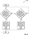
- FIG. 4 is a flowchart illustrating an example method 400 for alerting a flight crew of aircraft 10 of a relevant condition, such as a "status" and "advisory" of a configuration of a system 38, associated with aircraft 10.
- Method 400 may also be used for alerting a crew of a mobile platform of a relevant condition.
- Method 400 may be performed using CAS 24.
- blocks S41 0 and onward of method 400 may be stored in the form of instructions 32 on computer 26 and executed by data processor 28 of computer 26.
- computer 26 evaluates whether a notification has been received of an occurrence of a manual system configuration of a system 38 of aircraft 10. If a notification of the manual system configuration is received, control flow proceeds to block S420. If no notification of the manual system configuration is received, control flow proceeds for block S430.
- First indication 41 may include a textual message, as described herein.
- computer 26 evaluates whether a notification has been received of an occurrence of an automated system configuration of the system 38 of aircraft 10.
- the automated system configuration of the system 38 may perform equivalent actions on the system 38 as the manual system configuration of the system 38 as evaluated at block S410. If a notification of the occurrence of the automated system configuration is received, control flow proceeds to block S440. If no notification of the automated system configuration is received, control flow returns to block S410.
- Second indication 42 may include a textual message 44A, for example a "status" message such as the first indication 41 as defined by block S420, in combination with a supplemental indication 44B which may be in the form of a graphical indication, and may function as an "advisory" message indicating that the configuration of the system 38 was performed automatically.
- a textual message 44A for example a "status” message such as the first indication 41 as defined by block S420
- supplemental indication 44B which may be in the form of a graphical indication, and may function as an "advisory" message indicating that the configuration of the system 38 was performed automatically.
- supplemental indication 44B may comprise a graphical indication and/or a textual indication.
- textual message 44A and supplemental indication 44B may be displayed together as a single line item in CAS display area 16A.
- textual message 44A and supplemental indication 44B may be displayed laterally adjacent one another in CAS display area 16A.
- textual message 44A and supplemental indication 44B may be displayed in any suitable manner to achieve visual cohesion allowing textual message 44A and associated supplemental indication 44B to be interpreted together as second indication 42.
- Method 400 may also comprise removing second indication 42 from CAS display area 16A upon conclusion of the relevant condition or configuration of the system 38.
- a supplemental indication 44B to provide, for example, an "advisory" message, to provide the same or a similar function or purpose as an "advisory” message, to supplement a textual message or "status" indication in a second indication 42 to indicate an automatic configuration or reconfiguration (for example, as opposed to a manual configuration or reconfiguration performed by the flight crew) may reduce the number of other advisories that are displayed, for example on a CAS display area 16A, to the flight crew.
- the supplemental indication 44B of a second indication 42 may thus be used in place of an additional or separate "advisory" indication or alert of a configuration being performed automatically that might take up more real estate on a display or be distracting to the flight crew. As such, it may be easier for the flight crew to pick out and identify other advisories or alerts that may be displayed, for example, in a case of loss of redundancy or fault in a system.
- Second indication 42 may provide information to the flight crew about the relevant condition in a clear and integrated manner that is intuitive and relatively easy to interpret by the flight crew and may reduce clutter from advisory messages to the flight crew.
- the second indication 42 may provide information to the flight crew about the relevant condition without providing a full "advisory" message. This and the adjacent location of textual message 44A and supplemental indication 44B may contribute toward reducing the flight crew's workload during critical periods requiring the flight crew's attention.
- a second indication 42 having a textual message 44A and a supplemental indication 44B disclosed herein, and an associated reduction in "advisory” messages may avoid the flight crew from becoming desensitized to more important "advisory" messages.
Abstract
Description
- This application relates generally to aircraft and other mobile platforms, and more particularly, but not exclusively, to crew alerting systems for such aircraft or mobile platforms. This application claims priority from US Provisional Patent Application No.
US62/776,749, filed 7th December 2018 - Aircraft are typically equipped with a crew alerting system (CAS) to provide the flight crew with annunciations associated with various aircraft systems. The combination of engine indications and such crew alerting system is commonly known as an engine indication and crew alerting system (EICAS).
- Messages provided by conventional display-based crew alerting systems are textual messages typically of 12-42 characters and are organized in different colors corresponding to the level of the alert or relevant condition. These messages serve to alert the flight crew of system failures or inform the flight crew of a particular condition of a system of the aircraft. The messages are static in nature and the flight crew must often consult a source of information separate from the crew alerting system to supplement such messages.
- It is an aim of embodiments of the disclosure to improve upon such known systems.
- According to an aspect, there is provided a crew alerting system for a mobile platform, the system comprising: a display device defining a display area; one or more data processors operatively coupled to the display device; and non-transitory machine-readable memory operatively coupled to the one or more data processors and storing instructions executable by the one or more processors. The instructions may be configured to cause the one or more processors to, upon receiving notification of an occurrence of a manual system configuration associated with the mobile platform, generate a first output for causing the display device to display a first indication in the display area. The first indication may comprise a first textual message. Alternatively, or in addition, the instructions may be configured to cause the one or more processors to, upon receiving notification of an occurrence of an automated system configuration associated with the mobile platform, generate a second output for causing the display device to display a second indication in the display area. The second indication may comprise a second textual message accompanied by a supplemental indication.
- In some embodiments, the first and second textual messages are of a same color.
- In some embodiments, the first and second textual messages are white.
- In some embodiments, the first and second textual messages comprise a same content.
- In some embodiments, the supplemental indication is disposed on a same line as the second textual message.
- In some embodiments, the supplemental indication is disposed in front of the second textual message.
- In some embodiments, the supplemental indication has a different color than the second textual message.
- In some embodiments, the supplemental indication is adjacent to the second textual message.
- In some embodiments, the supplemental indication is a graphical indication.
- In some embodiments, the graphical indication comprises a circle.
- In some embodiments, the manual system configuration and the automated system configuration are associated with a same system of the aircraft.
- In some embodiments, the manual system configuration and the automated system configuration perform equivalent actions on the system of the aircraft.
- According to another aspect, there is provided an aircraft comprising a crew alerting system as described herein.
- According to another aspect, there is provided a crew alerting system for a mobile platform, the system comprising: a display device defining a display area; one or more data processors operatively coupled to the display device; and non-transitory machine-readable memory operatively coupled to the one or more data processors and storing instructions executable by the one or more processors and configured to cause the one or more processors to: upon receiving notification of an occurrence of an automated system configuration associated with the mobile platform, generate an output for causing the display device to display an indication in the display area, the indication comprising a textual message in a color associated with a status message accompanied by a graphical indication in a color associated with an advisory alert.
- According to another aspect, there is provided a method for alerting a crew of a mobile platform of a system configuration associated with the mobile platform using a display area of a crew alerting system of the mobile platform, the method comprising: upon receiving notification of an occurrence of a manual system configuration associated with the mobile platform, displaying a first indication in the display area of the crew alerting system of the mobile platform, the first indication comprising a first textual message; and upon receiving notification of an occurrence of an automated system configuration associated with the mobile platform, displaying a second indication in the display area of the crew alerting system of the mobile platform, the second indication comprising a second textual message accompanied by a supplemental indication.
- In some embodiments, the first and second textual messages are of a same color.
- In some embodiments, the first and second textual messages are white.
- In some embodiments, the first and second textual messages comprise a same content.
- In some embodiments, the supplemental indication is disposed on the same line as the second textual message.
- In some embodiments, the supplemental indication is disposed in front of the second textual message.
- In some embodiments, the supplemental indication has a different color than the second textual message.
- In some embodiments, the supplemental indication is adjacent the second textual message.
- In some embodiments, the supplemental indication is a graphical indication.
- In some embodiments, the graphical indication comprises a circle.
- In some embodiments, the manual system configuration and the automated system configuration are associated with a same system of the aircraft.
- In some embodiments, the manual system configuration and the automated system configuration perform equivalent actions on the system of the aircraft.
- Within the scope of this application it is expressly intended that the various aspects, embodiments, examples and alternatives set out in the preceding paragraphs, in the claims and/or in the following description and drawings, and in particular the individual features thereof, may be taken independently or in any combination. That is, all embodiments and/or features of any embodiment can be combined in any way and/or combination, unless such features are incompatible. The applicant reserves the right to change any originally filed claim or file any new claim accordingly, including the right to amend any originally filed claim to depend from and/or incorporate any feature of any other claim although not originally claimed in that manner.
- One or more embodiments of the disclosure will now be described, by way of example only, with reference to the accompanying figures, in which:
-
FIG. 1 shows an aircraft flight deck and a corresponding aircraft comprising the flight deck, according to an embodiment; -
FIG. 2 shows a schematic representation of a crew alerting system of the aircraft ofFIG. 1 , according to an embodiment; -
FIG. 3 shows a display area associated with the crew alerting system ofFIG. 2 , the display area including status indications; and -
FIG. 4 is a flowchart illustrating a method for alerting a crew of a mobile platform such as the aircraft ofFIG. 1 of an automated configuration associated with a system of the mobile platform. - The present disclosure describes systems, display devices and methods associated with crew alerting systems of aircraft and other mobile platforms. Even though various aspects of the present disclosure are described in the context of aircraft, it is understood that aspects disclosed herein are equally applicable to centralized alerting systems for other systems and mobile platforms (e.g., vehicles) such as trains, ships and busses for example. In various embodiments, the systems, display devices and methods disclosed herein may be considered to provide crew alerting systems of improved functionality compared to conventional crew alerting systems by providing awareness-enhancing indications while being mindful of the limited real estate available on an aircraft flight deck.
- In various embodiments, the systems, display devices and methods disclosed herein may, in some situations, provide enhanced awareness of a change in configuration of a component or system of the aircraft that has been executed either manually by the flight crew or automatically by an automated system of the aircraft. Accordingly, in some embodiments, the systems, display devices and methods disclosed herein may contribute toward enhancing awareness of the flight crew and alleviating the flight crew's workload at times when the flight crew is being alerted of a relevant condition requiring the flight crew's attention.
- Aspects of various embodiments are described through reference to the drawings.
-
FIG. 1 shows an example aircraft 10 (i.e., mobile platform) and a partial schematic representation offlight deck 12 which may be part ofaircraft 10.Aircraft 10 may be a corporate, private, commercial or any other type of aircraft. For example,aircraft 10 may be a fixed-wing aircraft. In various embodiments,aircraft 10 may be a narrow-body, twin engine jet airliner, a (e.g., ultra-long range) business jet, a twin-engine turboprop airliner or a regional jet airliner.Flight deck 12 may comprise additional or fewer elements than those shown and described herein.Flight deck 12 may compriseleft portion 12A intended to be used by a pilot (sometimes referred to as "captain") ofaircraft 10 andright portion 12B intended to be used by a co-pilot (sometimes referred to as "first officer") ofaircraft 10.Left portion 12A andright portion 12B may comprise functionally identical components so that at least some operational redundancy may be provided betweenleft portion 12A andright portion 12B offlight deck 12. As used herein, the term "flight crew" is intended to encompass one or more individuals responsible for the operation ofaircraft 10 during flight. Such individuals may, for example, include the pilot and/or the co-pilot. Similarly, the term "crew" is intended to encompass one or more individuals responsible for or associated with the operation of a mobile platform comprising a crew alerting system as disclosed herein. -
Flight deck 12 may comprise one ormore display devices 14 providingrespective display areas 16. In the example configuration offlight deck 12 shown inFIG. 1 , leftportion 12A andright portion 12B may each comprise twodisplay devices 14 and anadditional display device 14 may be provided inpedestal region 18 offlight deck 12.Display device 14 provided inpedestal region 18 may be shared between the pilot and the co-pilot during normal operation ofaircraft 10.Display devices 14 may include one or more cathode-ray tubes (CRTs), liquid crystal displays (LCDs), plasma displays, light-emitting diode (LED) based displays, organic light-emitting diode (OLED) based displays, or any known or other type of display device that may be suitable for use inflight deck 12.Display devices 14 may be configured to dynamically display operational and status information about various systems ofaircraft 10, information related to flight/mission planning, maps and any other information that may be useful for the flight crew (e.g., pilot(s)) during the operation ofaircraft 10.Display devices 14 may facilitate dialog between the flight crew and various systems ofaircraft 10 via suitable graphical user interfaces.Flight deck 12 may comprise one or more data input devices such as, for example, one or morecursor control devices 20, one or moremulti-function keypads 22 and one or more (e.g., standalone or multifunction)controllers 23 that may permit data entry by the flight crew. For example, such controller(s) 23 may be disposed in the glare shield above one ormore display devices 14. - One or more of
display devices 14 may compriseCAS display area 16A dedicated to centralizedcrew alerting system 24 shown schematically inFIG. 2 and referred hereinafter as "CAS 24", during one or more phases of operation ofaircraft 10. In some embodiments, a single instance ofCAS display area 16A may be displayed on adisplay device 14 that is conveniently located to be visible by both the pilot and the co-pilot. Alternatively, in some embodiments, more than one instance ofCAS display area 16A may be displayed on more than onerespective display device 14. In some embodiments, thedisplay device 14 on whichCAS display area 16A is provided may also include engine indications and thereforeCAS display area 16A may be part of an engine indication and crew alerting system (EICAS). In some embodiments,CAS display area 16A may be selectively displayed on one ormore display devices 14 offlight deck 12 based on input from the flight crew. - It is understood that
CAS display area 16A and the display of its contents is not limited to one ormore display devices 14onboard aircraft 10. For example,CAS display area 16A could, alternatively or in addition, be provided on a display device that is off ofaircraft 10. For example,CAS display area 16A could be provided on a display device of a ground station to alert a ground-based operator ofaircraft 10 or support (e.g., maintenance) personnel. Hence, even though the present disclosure refers to alerting a flight crew ofaircraft 10, it is understood that relevant information could be transmitted fromaircraft 10 to a location remote from aircraft 10 (e.g., ground station) in order to alert an individual at such location in accordance with aspects of the present disclosure. -
FIG. 2 shows a schematic representation of anexample CAS 24 which may be part ofaircraft 10.CAS 24 may be integrated withflight deck 12.CAS 24 may comprise one or more computers 26 (referred hereinafter in the singular) operatively coupled to one or more display devices 14 (referred hereinafter in the singular) offlight deck 12. Computer 26 may comprise one or more data processors 28 (referred hereinafter in the singular) and one or more computer-readable memories 30 (referred hereinafter in the singular) storing machine-readable instructions 32 executable bydata processor 28 and configured to causedata processor 28 to generate one or more outputs 34 (referred hereinafter in the singular).Output 34 may comprise one or more signals for causingdisplay device 14 ofaircraft 10 to displayCAS display area 16A and its contents. - Computer 26 may receive input(s) 36 in the form of data or information that may be processed by
data processor 28 based oninstructions 32 in order to generateoutput 34. For example,input 36 may comprise information (data) indicative of a configuration or reconfiguration associated with one ormore systems 38 ofaircraft 10. -
Systems 38 ofaircraft 10 may include, for example, a hydraulic system, an electrical system, a fuel system, flight control surfaces, a navigation system, an engine and/or any other aircraft systems. - One or
more systems 38 ofaircraft 10 may be controlled or actuated by acontrol system 50, for example, to configure or reconfigure asystem 38 or various components of asystem 38. In some embodiments,control system 50 may comprise one or more computers, for example, similar to computer 26 as described herein. In some embodiments,control system 50 may be a part of computer 26. As such, an automated configuration of asystem 38 may be caused bycontrol system 50, in an example, without any manual input from the flight crew.Control system 50 can be considered part of an avionics suite ofaircraft 10. For example,control system 50 can be configured to carry out additional functions than those described herein. In some embodiments,control system 50 can be of the type known as a flight control computer (FCC) ofaircraft 10. In some embodiments,control system 50 can include a fly-by-wire control system ofaircraft 10. - One or
more systems 38 ofaircraft 10 may also be controlled or actuated by the flight crew directly accessing asystem 38, for example, to configure or reconfigure asystem 38 or various parameters of asystem 38. The flight crew may also control one ormore systems 38 by way of manual input to controlsystem 50. As such, a manual configuration of asystem 38 may be caused by a manual action performed by the flight crew. In some embodiments, the same change tosystem 38 results from either a manual system configuration or an automated system configuration. Furthermore, in some embodiments a manual system configuration and an automated system configuration may perform equivalent actions on asystem 38 of the aircraft. - In some embodiments,
input 36 may alternatively or in addition comprise information (data) indicative of, or notification of, occurrence of a configuration associated with one ormore systems 38 ofaircraft 10 and whether the configuration associated with one ormore systems 38 ofaircraft 10 was an automated configuration or a manual configuration. Examples of configuration changes could include: a switch from a magnetic heading to a true heading or vice versa in a navigation system, an activation or deactivation of a hydraulic pump, a change in position of a flight control surface, discharge of a fire extinguishing bottle, and opening or closing of a bleed air system valve. - In some embodiments, input(s) 36 may include or be indicative of sensed signals acquired via one or more (e.g., pressure, position, acceleration, temperature or other)
sensors 40 associated with one ormore aircraft systems 38. Accordingly, input(s) 36 may comprise one or more sensed parameters indicative of one or more states or configurations of aircraft system(s) 38. - As described further below, computer 26 may, based on input(s) 36, generate
output 34 for causingdisplay device 14 to display one or more combined advisory and status indications as described below and associated with a configuration of asystem 38 ofaircraft 10 inCAS display area 16A. - Computer 26 may be part of an avionics suite of
aircraft 10. For example, in some embodiments, computer 26 may carry out additional functions than those described herein including the management of one or more graphic user interfaces offlight deck 12 and/or other part(s) ofaircraft 10. In various embodiments, computer 26 may comprise more than one computer or data processor where the methods disclosed herein (or part(s) thereof) could be performed using a plurality of computers or data processors, or, alternatively, be performed entirely using a single computer or data processor. In some embodiments, computer 26 could be physically integrated with (e.g., embedded in)display device 14. -
Data processor 28 may comprise any suitable device(s) configured to cause a series of steps to be performed by computer 26 so as to implement a computer-implemented process such thatinstructions 32, when executed by computer 26 or other programmable apparatus, may cause the functions/acts specified in the methods described herein to be executed. -
Memory 30 may comprise any suitable known or other machine-readable storage medium.Memory 30 may comprise non-transitory computer readable storage medium.Memory 30 may comprise any storage means (e.g. devices) suitable for retrievably storing machine-readable instructions 32 executable bydata processor 28. - Various aspects of the present disclosure may be embodied as systems, devices, methods and/or computer program products. Accordingly, aspects of the present disclosure may take the form of an entirely hardware embodiment, an entirely software embodiment (including firmware, resident software, micro-code, etc.) or an embodiment combining software and hardware aspects. Furthermore, aspects of the present disclosure may take the form of a computer program product embodied in one or more non-transitory computer readable medium(ia) (e.g., memory 30) having computer readable program code (e.g., instructions 32) embodied thereon. The computer program product may, for example, be executed by computer 26 to cause the execution of one or more methods disclosed herein in entirety or in part.
- Computer program code for carrying out operations for aspects of the present disclosure in accordance with
instructions 32 may be written in any combination of one or more programming languages. Such program code may be executed entirely or in part by computer 26 or other data processing device(s). It is understood that, based on the present disclosure, one skilled in the relevant arts could readily write computer program code for implementing the methods disclosed herein. - In some embodiments,
crew alerting system 24 may comprisedisplay device 14 definingCAS display area 16A dedicated tocrew alerting system 24.Data processor 28 of computer 26 may be operatively coupled todisplay device 14. Machine-readable memory 30 may be operatively coupled todata processor 28 andstore instructions 32 executable byprocessor 28.Such instructions 32 may be configured to causeprocessor 28 to use data representative of input(s) 36 and generateoutput 34 configured to causedisplay device 14 to display a first indication 41 and/or a second indication 42 (for example, as shown inFIG. 3 and described in further detail below). - The data used by
data processor 28 may be indicative of a condition such as a configuration or reconfiguration associated with asystem 38, and whether such configuration was caused manually or automatically. The existence of a particular configuration may be based on the evaluation of a logical expression such as, for example, the comparison of a sensed value to a threshold value. Accordingly, the data indicative of the existence of such relevant condition may be binary in nature based on whether the logical expression evaluated is true or false. For example, such relevant condition may include a system degradation (e.g., failure), non-normal condition or state associated with one or more ofaircraft systems 38. - In some embodiments, data used by
data processor 28 may include a substantially real-time value of a variable ofsystem 38, and the variable may define a parameter or a configuration of asystem 38 or a component ofsystem 38. Such a value may be acquired viasensor 40. The variable value may be indicative of a configuration ofsystem 38. Non-limiting examples of such variables may include: a status of a fuel pump ofaircraft 10, a rotation speed (e.g., RPM) associated with an auxiliary power unit (APU) ofaircraft 10 during start-up, a quantity of fuel remaining in a fuel tank ofaircraft 10, an outside temperature indicating an icing risk, a position of a flight control surface ofaircraft 10, a temperature inside a cabin ofaircraft 10 and a pressure inside the cabin ofaircraft 10. Aspects of the present disclosure are not intended to be limited to the variables recited herein as examples. Instead, aspects of the present disclosure may be applicable to any suitable known or other relevant conditions that may be indicated via traditional or other aircraft crew alerting systems. - In some embodiments, data used by
data processor 28 may indicate whether a configuration or reconfiguration or asystem 38 was successfully completed, and whether such a configuration was commanded manually by the flight crew or automatically. -
FIG. 3 shows aCAS display area 16A associated withCAS 24 ofFIG. 2 whereCAS display area 16A includes a first indication 41 and a second indication 42. -
CAS display area 16A may be a sub-region oflarger display area 16 ofdisplay device 14. For example,CAS display area 16A may be disposed adjacent to engine-related indications and thereforeCAS display area 16A may, in some embodiments, be considered part of an EICAS. - In some embodiments, multiple first indications 41 and/or multiple second indications 42 may be displayed in
CAS display area 16A. - A "status" may be understood as a specific aircraft system condition that is recognized using a visual indication, but does not require an alert and does not require flight crew response. These types of messages are sometimes used to determine airplane dispatch capability for subsequent flights.
- An "alert" may be understood as a term used to describe a flight deck indication meant to attract the attention of and identify to the flight crew a non-normal operational or airplane system condition. Alerts may be classified at levels or categories corresponding to Warnings, Cautions, and Advisories, as discussed in further detail below. Alert indications may also include non-normal range markings (for example, exceedences on instruments and gauges.)
- An "advisory" may be understood as the level or category of alert for conditions that require flight crew awareness and may require subsequent flight crew response.
- Indications (e.g., status, alert, advisory) may be displayed in
CAS display area 16A in a color that is indicative of the criticality or level of alert of an associated relevant condition to provide the flight crew with a visual indication of the condition and its priority. - For example, red may be used for an indication associated with a "warning-alert" level requiring immediate awareness and action by the flight crew, amber or yellow may be used for an indication associated with a "caution-alert" level requiring immediate awareness and subsequent action by the flight crew, cyan or any colors other than green or red may be used for an indication associated with an "advisory" level requiring crew awareness, and white may be used for a status indication associated with a system state.
- First indication 41 may provide an indication or message of a system condition on
CAS display area 16A. In some embodiments, first indication 41 may be a "status" indication and may be displayed in white to indicate that it represents a system state. In some embodiments, a first indication 41 may include one or more textual messages. In some embodiments, a textual message of first indication 41 may be longer than 42 character or may be relatively short (e.g., less than 42 characters), and may be binary in nature and displayed based on the evaluation of a logical expression, for example, whether or not a system has been configured or reconfigured. For example, a textual message of first indication 41 may be displayed when an associated logical expression is true and may be hidden or removed fromCAS display area 16A when the associated logical expression is false. - In some embodiments, a first indication 41 may act as confirmation to the flight crew that a
system 38 ofaircraft 10 has been reconfigured manually, for example, for the remainder of the flight. As such, first indication 41 may show thatsystem 38 is configured as per the intent of the flight crew (for example, the pilot). - As shown in an example in
FIG. 3 , a first indication 41 may include a textual message containing the text "SYSTEM RECONFIG" displayed in the color white. In this specific example, "SYSTEM RECONFIG" may represent a status indication associated with a system state, namely that asystem 38 has been reconfigured by way of a manual input from the flight crew, and does not require an alert and does not require a flight crew response. -
FIG. 3 also illustrates a second indication 42. Second indication 42 may provide an indication or message of a combined "status" and "advisory" message, in particular, a system condition "status" accompanied by an "advisory" alert to the flight crew. In some embodiments, second indication 42 may include one or moretextual messages 44A as "status" indications and one or moresupplemental indications 44B as "advisory" indications.Supplemental indication 44B may accompanytextual message 44A, and may be displayed and hidden simultaneously withtextual message 44A. In some embodiments, atextual message 44A and asupplemental indication 44B of a second indication 42 may be displayed inCAS display area 16A adjacent one another. - In some embodiments,
textual message 44A of second indication 42 may have any or all of the same text, shape, color, and position of first indication 41. In an example,textual message 44A of second indication 42 and the textual message of first indication 41 may both contain white text.Textual message 44A may also thus perform the same "status" indication function for the same system as an associated first indication 41. -
Supplemental indication 44B may comprise a textual or a non-textual indication to perform an "advisory" indication function. For example,supplemental indication 44B may comprise an alphanumeric indication such as one or more numerical values and/or one or more textual indications that may indicate additional configuration details or variables associated with the relevant condition indicated bytextual message 44A. - Alternatively or in addition,
supplemental indication 44B may comprise a graphical (e.g., pictorial) indication which may facilitate the interpretation ofsupplemental indication 44B by the flight crew. The term "graphical" is intended to encompass any non-textual indications such as, for example, pictures, symbols, diagrams, curves, colored labels, segments, carets, connectors, markers, icons, bars and circles. The use of graphical indications may be preferred in some situations to facilitate the interpretation ofsupplemental indication 44B by providing "at-a-glance" information without having to read an alphanumeric message. - In some embodiments,
supplemental indication 44B may have a same color astextual message 44A, such as white, for example. In some embodiments,supplemental indication 44B may have a different color thantextual message 44A. - In an example,
supplemental indication 44B may be a graphical indication of a cyan circle, with or without fill. In other examples,supplemental indication 44B may form a different shape, such as a triangle or a square, or a graphical image such as a smiley face, or be different in color. - In some embodiments, a second indication 42 (for example, a "SYSTEM RECONFIG" accompanied by a cyan circle) may be displayed at a location on
CAS display area 16A that corresponds at least in part with a location onCAS display area 16A at which a first indication 41 for the same configuration and/or reconfiguration (for example, a "SYSTEM RECONFIG") is displayed. For example, in some embodimentstextual message 44A (for example, "SYSTEM RECONFIG") of second indication 42 may be displayed at the same location onCAS display area 16A as the textual message of first indication 41 (for example, "SYSTEM RECONFIG"). - In some embodiments, all or part of second indication 42 may be displayed in
CAS display area 16A in a color that is indicative of the criticality or level of alert associated with the "status" system of the relevant condition indicated bytextual message 44A, such as a configuration or reconfiguration of asystem 38, to provide the flight crew a visual indication of the condition and its priority. -
Supplemental indication 44B may be indicative of a type of configuration or reconfiguration performed on an associatedsystem 38. For example, the presence of asupplemental indication 44B in a second indication 42 may be associated with an automated configuration or reconfiguration of the associatedsystem 38. Similarly, the absence ofsupplemental indication 44B in a second indication 42, or simply the presence of a first indication 41 associated with the configuration or reconfiguration of the associatedsystem 38 may indicate that the configuration or reconfiguration indicated bytextual message 44A or first indication 41 was performed manually by the flight crew. Accordingly,supplemental indication 44B may be an indication that a configuration or reconfiguration was performed automatically, for example, bycontrol system 50. - In some embodiments, the presentation or display of
supplemental indication 44B may supplementtextual message 44A such that the flight crew is alerted of the same condition or configuration status as provided by first indication 41, while further alerting the flight crew that they did not perform any manual controls themselves to lead to the status ofsystem 38, however, the status was achieved automatically, for example bycontrol system 50. In some embodiments, the same change tosystem 38 results from either a manual configuration or an automated configuration. Furthermore, in some embodiments a manual system configuration and an automated system configuration may perform equivalent actions on asystem 38 of the aircraft. - Thus, in an example the combination of the color of
textual message 44A andgraphical indication 44B may be used for a second indication 42 associated with a type of system configuration or reconfiguration. - As shown in
FIG. 3 ,supplemental indication 44B may accompanytextual message 44A in a second indication 42 in a singleCAS display area 16A that is dedicated toCAS 24. In some embodiments,textual message 44A and an accompanyingsupplemental indication 44B may be displayed together as a single line item forming second indication 42 inCAS display area 16A. In some embodiments,supplemental indication 44B may be disposed in front oftextual message 44A. - For example,
textual message 44A andsupplemental indication 44B may be displayed laterally adjacent one another and together inCAS display area 16A. Alternatively,textual message 44A and associatedsupplemental indication 44B may be displayed as adjacent line items in some embodiments due to a length oftextual message 44A and/or an amount of display space required for associatedsupplemental indication 44B. In some embodiments,textual message 44A and associatedsupplemental indication 44B may be considered to be displayed together to achieve visual cohesion allowingtextual message 44A and associatedsupplemental indication 44B to be interpreted together as a second indication 42. In some embodiments, visual cohesion may be achieved by proximity oftextual message 44A and associatedsupplemental indication 44B. For example,textual message 44A and associatedsupplemental indication 44B may be positioned to have a vertical and/or lateral space (gap) of less than about 0.5 inch (13 mm) between them. - As shown in the example illustrated in
FIG. 3 , a second indication 42 may include atextual message 44A containing the text "SYSTEM RECONFIG" in the color white accompanied by an adjacentsupplemental indication 44B that includes an image of a circle. In this specific example, "SYSTEM RECONFIG" may represent a "status" indication that asystem 38 has been reconfigured.Supplemental indication 44B may represent an "advisory" indication to graphically indicate that the system reconfiguration was automated, for example, performed bycontrol system 50 without manual input from the flight crew. Thesupplemental indication 44B may be cyan in color (indicating an automated reconfiguration). - In some embodiments, an automatic system reconfiguration may be the result of one or more actions or sequences of events within
aircraft 10. For example, in a sequence of fire extinguishing, certain aircraft systems (such as fuel and hydraulic systems of the engine) may be configured to be shut down automatically. - Examples of text in a
textual message 44A include "NAV MAG HEADING" (for example, related to a magnetic heading system configuration), "L BLEED VALVE OFF" (for example, related to a bleed air system configuration), "SPOILERS DEPLOYED" (for example, related to a flight control surface system configuration), "L PRIMARY FUEL PUMP OFF" (for example, related to a fuel pump system configuration), and "FIRE BOTTLE DISCHARGED" (for example, related to a fire extinguishing bottle system configuration), which may represent "status" indications of a configuration or reconfiguration of aparticular system 38. - In some embodiments, second indication 42 may be displayed in
CAS display area 16A instead of computer 26 generating an "advisory" output to causedisplay device 14 to display an "advisory" message associated with a system onCAS display area 16A. - In some embodiments, a configuration of a
system 38 ofaircraft 10 may be overridden or disabled. Accordingly, second indication 42 may be removed fromCAS display area 16A. In some embodiments, second indication 42 may be replaced by another message. -
FIG. 4 is a flowchart illustrating anexample method 400 for alerting a flight crew ofaircraft 10 of a relevant condition, such as a "status" and "advisory" of a configuration of asystem 38, associated withaircraft 10.Method 400 may also be used for alerting a crew of a mobile platform of a relevant condition.Method 400 may be performed usingCAS 24. For example, blocks S41 0 and onward ofmethod 400 may be stored in the form ofinstructions 32 on computer 26 and executed bydata processor 28 of computer 26. - At block S410, computer 26 evaluates whether a notification has been received of an occurrence of a manual system configuration of a
system 38 ofaircraft 10. If a notification of the manual system configuration is received, control flow proceeds to block S420. If no notification of the manual system configuration is received, control flow proceeds for block S430. - At block S420, upon receiving notification of the occurrence of the manual system configuration of a
system 38 ofaircraft 10, computer 26 displays a first indication 41 inCAS display area 16A. First indication 41 may include a textual message, as described herein. - At block S430, computer 26 evaluates whether a notification has been received of an occurrence of an automated system configuration of the
system 38 ofaircraft 10. The automated system configuration of thesystem 38 may perform equivalent actions on thesystem 38 as the manual system configuration of thesystem 38 as evaluated at block S410. If a notification of the occurrence of the automated system configuration is received, control flow proceeds to block S440. If no notification of the automated system configuration is received, control flow returns to block S410. - At block S440, upon receiving notification of the automated system configuration of the
system 38 ofaircraft 10, computer 26 displays a second indication 42 inCAS display area 16A. Second indication 42 may include atextual message 44A, for example a "status" message such as the first indication 41 as defined by block S420, in combination with asupplemental indication 44B which may be in the form of a graphical indication, and may function as an "advisory" message indicating that the configuration of thesystem 38 was performed automatically. - In some embodiments,
supplemental indication 44B may comprise a graphical indication and/or a textual indication. - In some embodiments,
textual message 44A andsupplemental indication 44B may be displayed together as a single line item inCAS display area 16A. For example,textual message 44A andsupplemental indication 44B may be displayed laterally adjacent one another inCAS display area 16A. In some embodiments,textual message 44A andsupplemental indication 44B may be displayed in any suitable manner to achieve visual cohesion allowingtextual message 44A and associatedsupplemental indication 44B to be interpreted together as second indication 42. -
Method 400 may also comprise removing second indication 42 fromCAS display area 16A upon conclusion of the relevant condition or configuration of thesystem 38. - Conveniently, having a
supplemental indication 44B to provide, for example, an "advisory" message, to provide the same or a similar function or purpose as an "advisory" message, to supplement a textual message or "status" indication in a second indication 42 to indicate an automatic configuration or reconfiguration (for example, as opposed to a manual configuration or reconfiguration performed by the flight crew) may reduce the number of other advisories that are displayed, for example on aCAS display area 16A, to the flight crew. Thesupplemental indication 44B of a second indication 42 may thus be used in place of an additional or separate "advisory" indication or alert of a configuration being performed automatically that might take up more real estate on a display or be distracting to the flight crew. As such, it may be easier for the flight crew to pick out and identify other advisories or alerts that may be displayed, for example, in a case of loss of redundancy or fault in a system. - Second indication 42 may provide information to the flight crew about the relevant condition in a clear and integrated manner that is intuitive and relatively easy to interpret by the flight crew and may reduce clutter from advisory messages to the flight crew. The second indication 42 may provide information to the flight crew about the relevant condition without providing a full "advisory" message. This and the adjacent location of
textual message 44A andsupplemental indication 44B may contribute toward reducing the flight crew's workload during critical periods requiring the flight crew's attention. - Furthermore, more and more aircraft functions are becoming automated, and there is a trend towards use of a single pilot cockpit, which may incur an increase in "advisory"-type messages displayed to flight crew. Thus, various embodiments of a second indication 42 having a
textual message 44A and asupplemental indication 44B disclosed herein, and an associated reduction in "advisory" messages, may avoid the flight crew from becoming desensitized to more important "advisory" messages. - The above description is meant to be by way of example only, and one skilled in the relevant arts will recognize that changes may be made to the embodiments described without departing from the scope of the disclosure. The present disclosure may be embodied in other specific forms without departing from the subject matter of the claims. Also, one skilled in the relevant arts will appreciate that while the systems, devices and methods disclosed and shown herein may comprise a specific number of elements/steps, the systems, devices and methods could be modified to include additional or fewer of such elements/steps. The present disclosure is also intended to cover and embrace all suitable changes in technology. Modifications which fall within the scope of the present disclosure will be apparent to those skilled in the art, in light of a review of this disclosure, and such modifications are intended to fall within the appended claims. Also, the scope of the claims should not be limited by the preferred embodiments set forth in the examples, but should be given the broadest interpretation consistent with the description as a whole.
Claims (15)
- A crew alerting system for a mobile platform (10), the system comprising:a display device (14) defining a display area (16);one or more data processors (28) operatively coupled to the display device (14); andnon-transitory machine-readable memory (30) operatively coupled to the one or more data processors (28) and storing instructions (32) executable by the one or more processors (28) and configured to cause the one or more processors to:upon receiving notification of an occurrence of a manual system configuration associated with the mobile platform (10), generate a first output for causing the display device (14) to display a first indication (41) in the display area (16), the first indication (41) comprising a first textual message; andupon receiving notification of an occurrence of an automated system configuration associated with the mobile platform (10), generate a second output for causing the display device (14) to display a second indication (42) in the display area (16), the second indication (42) comprising a second textual message (44A) accompanied by a supplemental indication (44B).
- The crew alerting system of claim 1, wherein the first and second textual messages (41, 44A) are of a same color.
- The crew alerting system of claim 1 or claim 2, wherein the first and second textual messages (41, 44A) are white.
- The crew alerting system of any one of claims 1 to 3, wherein the first and second textual messages (41, 44A) comprise a same content.
- The crew alerting system of any one of claims 1 to 4, wherein the supplemental indication (44B) is disposed on a same line as the second textual message (44A).
- The crew alerting system of any one of claims 1 to 5, wherein the supplemental indication (44B) is disposed in front of the second textual message (44A).
- The crew alerting system of any one of claims 1 to 6, wherein the supplemental indication (44B) has a different color than the second textual message (44A).
- The crew alerting system of any one of claims 1 to 7, wherein the supplemental indication (44B) is adjacent to the second textual message (44A).
- The crew alerting system of any one of claims 1 to 8, wherein the supplemental indication (44B) is a graphical indication.
- The crew alerting system of claim 9, wherein the graphical indication comprises a circle.
- The crew alerting system of any one of claims 1 to 10, wherein the manual system configuration and the automated system configuration are associated with a same system of the mobile platform (10).
- The crew alerting system of claim 11, wherein the manual system configuration and the automated system configuration perform equivalent actions on the system of the mobile platform (10).
- An aircraft comprising the crew alerting system of any one of claims 1 to 12.
- A method for alerting a crew of a mobile platform (10) of a system configuration associated with the mobile platform using a display area (16) of a crew alerting system (14) of the mobile platform, the method comprising:upon receiving notification of an occurrence of a manual system configuration associated with the mobile platform (10), displaying a first indication (41) in the display area (16) of the crew alerting system (14) of the mobile platform, the first indication (41) comprising a first textual message; andupon receiving notification of an occurrence of an automated system configuration associated with the mobile platform (10), displaying a second indication (42) in the display area (16) of the crew alerting system (14) of the mobile platform, the second indication (42) comprising a second textual message (44A) accompanied by a supplemental indication (44B).
- The method of claim 15, wherein the first and second textual messages (41, 44A) are of a same color, optionally white.
Applications Claiming Priority (1)
| Application Number | Priority Date | Filing Date | Title |
|---|---|---|---|
| US201862776749P | 2018-12-07 | 2018-12-07 |
Publications (1)
| Publication Number | Publication Date |
|---|---|
| EP3663998A1 true EP3663998A1 (en) | 2020-06-10 |
Family
ID=68762517
Family Applications (1)
| Application Number | Title | Priority Date | Filing Date |
|---|---|---|---|
| EP19212757.9A Pending EP3663998A1 (en) | 2018-12-07 | 2019-12-01 | Crew alerting systems and methods for mobile platforms |
Country Status (4)
| Country | Link |
|---|---|
| US (1) | US20200184831A1 (en) |
| EP (1) | EP3663998A1 (en) |
| CN (1) | CN111284715A (en) |
| CA (1) | CA3063863A1 (en) |
Families Citing this family (2)
| Publication number | Priority date | Publication date | Assignee | Title |
|---|---|---|---|---|
| US11586196B2 (en) * | 2020-01-22 | 2023-02-21 | Honeywell International Inc. | Approach mode activation monitoring function and automatic activation in an event of pilot incapacitation |
| US20230377468A1 (en) * | 2022-05-20 | 2023-11-23 | The Boeing Company | Prioritizing crew alerts |
Citations (1)
| Publication number | Priority date | Publication date | Assignee | Title |
|---|---|---|---|---|
| WO2017191543A1 (en) * | 2016-05-03 | 2017-11-09 | Bombardier Inc. | Crew alerting systems and methods for mobile platforms |
Family Cites Families (7)
| Publication number | Priority date | Publication date | Assignee | Title |
|---|---|---|---|---|
| RU2018966C1 (en) * | 1992-02-20 | 1994-08-30 | Владимир Андреевич Зиберов | Method of intellectual support of activity of flying vehicle crew |
| US5508928A (en) * | 1992-11-17 | 1996-04-16 | Honeywell, Inc. | Aircraft survivability system state management |
| FR2980616B1 (en) * | 2011-09-23 | 2014-08-08 | Thales Sa | ALERT SYSTEM FOR A DRIVER OPERATOR OF AN AIRCRAFT |
| US20160272341A1 (en) * | 2015-03-17 | 2016-09-22 | Airbly Inc. | Aircraft environmental monitoring and alerting device |
| US10315778B2 (en) * | 2015-09-25 | 2019-06-11 | The Beoing Company | Airplane status system |
| US9663241B1 (en) * | 2016-04-19 | 2017-05-30 | Honeywell International Inc. | Speed change and acceleration point enhancement system and method |
| US9969503B2 (en) * | 2016-07-21 | 2018-05-15 | Rockwell Collins, Inc. | Head-up display (HUD) stall recovery symbology |
-
2019
- 2019-12-01 EP EP19212757.9A patent/EP3663998A1/en active Pending
- 2019-12-05 CA CA3063863A patent/CA3063863A1/en active Pending
- 2019-12-05 US US16/704,457 patent/US20200184831A1/en active Pending
- 2019-12-06 CN CN201911241028.3A patent/CN111284715A/en active Pending
Patent Citations (1)
| Publication number | Priority date | Publication date | Assignee | Title |
|---|---|---|---|---|
| WO2017191543A1 (en) * | 2016-05-03 | 2017-11-09 | Bombardier Inc. | Crew alerting systems and methods for mobile platforms |
Also Published As
| Publication number | Publication date |
|---|---|
| CN111284715A (en) | 2020-06-16 |
| CA3063863A1 (en) | 2020-06-07 |
| US20200184831A1 (en) | 2020-06-11 |
Similar Documents
| Publication | Publication Date | Title |
|---|---|---|
| US10318057B2 (en) | Touch screen instrument panel | |
| AU2016208410B2 (en) | Airplane status system | |
| US11858654B2 (en) | Crew alerting systems and methods for mobile platforms | |
| CN109313042B (en) | Displaying performance limits in aircraft displays | |
| CN111038715B (en) | View guidance system and method for aircraft | |
| US20150348420A1 (en) | Awareness Enhancing Display For Aircraft | |
| EP2816432B1 (en) | Flight deck display systems and methods for visually indicating low speed change conditions during takeoff and landing | |
| US8751512B2 (en) | Method and device for managing information in an aircraft | |
| US20140156115A1 (en) | Method for displaying an aeronautical flight plan comprising a step of displaying and selecting the tasks to be accomplished before a change of flight phase | |
| CN107548450B (en) | System and method for assisting aircraft landing | |
| US20190265066A1 (en) | Trend indications for avionics systems | |
| EP3663998A1 (en) | Crew alerting systems and methods for mobile platforms | |
| US20170168680A1 (en) | Device and a method for assisting the piloting of an aircraft | |
| EP3828504A1 (en) | Aircraft display system and method | |
| CN117095517A (en) | Determining alert levels based on crew response | |
| Dillard | ARP-5364: Human factors criteria for the design of multifunction displays for transport category aircraft | |
| Juppet et al. | Advanced alerting system-Capabilities for part time display of vehicle parameters |
Legal Events
| Date | Code | Title | Description |
|---|---|---|---|
| PUAI | Public reference made under article 153(3) epc to a published international application that has entered the european phase |
Free format text: ORIGINAL CODE: 0009012 |
|
| STAA | Information on the status of an ep patent application or granted ep patent |
Free format text: STATUS: THE APPLICATION HAS BEEN PUBLISHED |
|
| AK | Designated contracting states |
Kind code of ref document: A1 Designated state(s): AL AT BE BG CH CY CZ DE DK EE ES FI FR GB GR HR HU IE IS IT LI LT LU LV MC MK MT NL NO PL PT RO RS SE SI SK SM TR |
|
| AX | Request for extension of the european patent |
Extension state: BA ME |
|
| STAA | Information on the status of an ep patent application or granted ep patent |
Free format text: STATUS: REQUEST FOR EXAMINATION WAS MADE |
|
| 17P | Request for examination filed |
Effective date: 20201210 |
|
| RBV | Designated contracting states (corrected) |
Designated state(s): AL AT BE BG CH CY CZ DE DK EE ES FI FR GB GR HR HU IE IS IT LI LT LU LV MC MK MT NL NO PL PT RO RS SE SI SK SM TR |
|
| STAA | Information on the status of an ep patent application or granted ep patent |
Free format text: STATUS: EXAMINATION IS IN PROGRESS |
|
| 17Q | First examination report despatched |
Effective date: 20210804 |