EP3663887A1 - Elektronisches gerät und verfahren zur automatischen bestimmung von steuerinformationen eines mobilen fahrzeugs, das ein führendes mobiles fahrzeug begleitet, computerprogramm dafür - Google Patents
Elektronisches gerät und verfahren zur automatischen bestimmung von steuerinformationen eines mobilen fahrzeugs, das ein führendes mobiles fahrzeug begleitet, computerprogramm dafür Download PDFInfo
- Publication number
- EP3663887A1 EP3663887A1 EP19212864.3A EP19212864A EP3663887A1 EP 3663887 A1 EP3663887 A1 EP 3663887A1 EP 19212864 A EP19212864 A EP 19212864A EP 3663887 A1 EP3663887 A1 EP 3663887A1
- Authority
- EP
- European Patent Office
- Prior art keywords
- data
- leading
- minimum
- aircraft
- mobile device
- Prior art date
- Legal status (The legal status is an assumption and is not a legal conclusion. Google has not performed a legal analysis and makes no representation as to the accuracy of the status listed.)
- Withdrawn
Links
- 238000000034 method Methods 0.000 title claims description 29
- 238000004590 computer program Methods 0.000 title claims description 3
- 238000005259 measurement Methods 0.000 claims abstract description 18
- 230000015572 biosynthetic process Effects 0.000 claims description 57
- 238000004364 calculation method Methods 0.000 claims description 29
- 238000012545 processing Methods 0.000 claims description 17
- 230000004807 localization Effects 0.000 description 23
- 230000006870 function Effects 0.000 description 18
- 238000012549 training Methods 0.000 description 8
- 229920000297 Rayon Polymers 0.000 description 5
- 230000006978 adaptation Effects 0.000 description 5
- 238000004891 communication Methods 0.000 description 5
- 239000002964 rayon Substances 0.000 description 5
- 230000009471 action Effects 0.000 description 4
- 230000008859 change Effects 0.000 description 3
- 238000001514 detection method Methods 0.000 description 3
- 108010006519 Molecular Chaperones Proteins 0.000 description 2
- 230000006399 behavior Effects 0.000 description 2
- 238000013016 damping Methods 0.000 description 2
- 238000013480 data collection Methods 0.000 description 2
- 238000010586 diagram Methods 0.000 description 2
- 239000007789 gas Substances 0.000 description 2
- 230000004048 modification Effects 0.000 description 2
- 238000012986 modification Methods 0.000 description 2
- 230000008569 process Effects 0.000 description 2
- 101100182248 Caenorhabditis elegans lat-2 gene Proteins 0.000 description 1
- 240000008042 Zea mays Species 0.000 description 1
- 230000001133 acceleration Effects 0.000 description 1
- 230000005540 biological transmission Effects 0.000 description 1
- 238000004422 calculation algorithm Methods 0.000 description 1
- 230000015556 catabolic process Effects 0.000 description 1
- 230000001276 controlling effect Effects 0.000 description 1
- 238000006731 degradation reaction Methods 0.000 description 1
- 230000000593 degrading effect Effects 0.000 description 1
- 238000011161 development Methods 0.000 description 1
- 229940082150 encore Drugs 0.000 description 1
- 230000010006 flight Effects 0.000 description 1
- 230000006872 improvement Effects 0.000 description 1
- 239000003607 modifier Substances 0.000 description 1
- 238000012544 monitoring process Methods 0.000 description 1
- 230000009257 reactivity Effects 0.000 description 1
- 230000001105 regulatory effect Effects 0.000 description 1
- 230000000717 retained effect Effects 0.000 description 1
- 230000007704 transition Effects 0.000 description 1
Images


Classifications
-
- G—PHYSICS
- G05—CONTROLLING; REGULATING
- G05D—SYSTEMS FOR CONTROLLING OR REGULATING NON-ELECTRIC VARIABLES
- G05D1/00—Control of position, course, altitude or attitude of land, water, air or space vehicles, e.g. using automatic pilots
- G05D1/10—Simultaneous control of position or course in three dimensions
- G05D1/101—Simultaneous control of position or course in three dimensions specially adapted for aircraft
- G05D1/104—Simultaneous control of position or course in three dimensions specially adapted for aircraft involving a plurality of aircrafts, e.g. formation flying
-
- B—PERFORMING OPERATIONS; TRANSPORTING
- B64—AIRCRAFT; AVIATION; COSMONAUTICS
- B64C—AEROPLANES; HELICOPTERS
- B64C39/00—Aircraft not otherwise provided for
- B64C39/02—Aircraft not otherwise provided for characterised by special use
- B64C39/024—Aircraft not otherwise provided for characterised by special use of the remote controlled vehicle type, i.e. RPV
-
- B—PERFORMING OPERATIONS; TRANSPORTING
- B64—AIRCRAFT; AVIATION; COSMONAUTICS
- B64U—UNMANNED AERIAL VEHICLES [UAV]; EQUIPMENT THEREFOR
- B64U10/00—Type of UAV
- B64U10/25—Fixed-wing aircraft
-
- B—PERFORMING OPERATIONS; TRANSPORTING
- B64—AIRCRAFT; AVIATION; COSMONAUTICS
- B64U—UNMANNED AERIAL VEHICLES [UAV]; EQUIPMENT THEREFOR
- B64U2201/00—UAVs characterised by their flight controls
- B64U2201/10—UAVs characterised by their flight controls autonomous, i.e. by navigating independently from ground or air stations, e.g. by using inertial navigation systems [INS]
- B64U2201/102—UAVs characterised by their flight controls autonomous, i.e. by navigating independently from ground or air stations, e.g. by using inertial navigation systems [INS] adapted for flying in formations
Definitions
- the present invention relates to the field of guiding mobile vehicles in formation.
- leader plane which will serve as a guide for the other planes sometimes called “wingers” or “escorts”.
- wingers or “escorts”.
- the pilots of these escort planes fly on sight to follow their leader.
- formation flights have been carried out in accordance with rules which specify the responsibilities of all players.
- the leader must keep a constant speed while not playing with the gas, stay away from extreme regimes in order to always leave a margin for the guides to accelerate or decelerate, carry out the transitions with progressiveness by giving maximum anticipation, transmit the tops , speed setpoints, altitudes and heading in a timely manner.
- the pilot of an escort plane must ensure safety by always having an eye on the leader and the other escorts in his field of vision and maintain a position allowing him to free himself if necessary.
- the spacing between mobile craft in formation, typically aircraft in a formation flight, is the parameter which dimensions the type of mission to be carried out.
- Maintaining these spaces is done today manually and for example in the following order: tiering, shrinking, spacing.
- the formation flight exists, it is different for the configuration where a leading plane is accompanied by an unmanned aircraft. There is no solution because an unmanned accompanying aircraft cannot be able to monitor its leader on sight. Even if this accompanying aircraft does have a pilot on the ground, the formation flight requires a reactivity that the only latency of communication between the ground and the edge can make it unacceptable. However, it could be useful for an unmanned accompanying mobile device to be able to fly in formation, so as to provide assistance to the protection mission of its leading mobile device.
- the invention proposes an electronic device for determining the piloting information of a mobile vehicle accompanying a leading mobile vehicle, this information being instructions for piloting the mobile accompanying vehicle and / or positional deviations between a current position of said leading mobile object and a current position of said accompanying mobile object, characterized in that it is suitable for collecting location data of the leading mobile object from actual location data originating from measurements relating to the current location of the leading mobile device and target trajectory data of the leading mobile device and to determine, as a function of said collected location data, piloting information for the accompanying mobile device as a function of '' a set of at least two values to respect in relation to the location defined by the data collected, said values to be respected both representative of values included among: a minimum staging value, a minimum shrinkage value, a minimum spacing value.
- the present invention provides a solution for guiding mobile vehicles in training, including, but not limited to, an unmanned accompanying mobile vehicle.
- This solution is based on the automation of support, making the mobile support unit autonomous to follow its leader.
- the present invention provides a mobile device accompanying a leading mobile device, comprising an electronic device for determining piloting information according to the first aspect of the invention and an automatic, semi-automatic or assisted piloting module. , adapted to automatically pilot said machine according to said information.
- the present invention provides a computer program comprising software instructions which, when executed by a computer, implement a method as defined above.
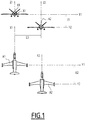
- the spacing is represented by the step E1, the withdrawal E2 and the spacing, E3.
- the leading aircraft A1 is an airplane with a pilot and the accompanying aircraft A2 is an aircraft, for example without pilot.
- flight management system in English "Flight Management System” or FMS, and with an automatic pilot (not shown).
- FMS flight Management System
- the accompanying aircraft A2 also comprises an electronic device for automatically determining piloting instructions 1, which in one embodiment is integrated within FMS.
- the device for automatically determining flight instructions 1 is suitable for collecting location data from the leading aircraft A1 and for determining, in particular as a function of the collected location data, flight instructions for the accompanying aircraft A2 as a function of set minimum values to be observed for staging, shrinking and spacing
- the FMS of the leading aircraft A1 is adapted for calculate the target 3D trajectory (3-dimensional geographic coordinates) of the aircraft A1, as a function of the geometry between the waypoints, the performance of the aircraft and the constraints of the flight plan (altitude, speed, time, slope ). This trajectory can be updated over time depending on certain factors (weather, regulatory, air traffic, etc.).
- the FMS of the leading aircraft A1 is adapted to establish its 3D vector at all times (3D position, 3D speed).
- the FMS of the aircraft A2 is also adapted to establish its 3D vector at all times.
- the aircraft A1 is further adapted to transmit in real time its 3D vector commonly established to the aircraft A2, via these wireless communication means.
- the aircraft A2 is in itself adapted to receive, via these means of wireless communication, the commonly established 3D vector of aircraft A1, and for processing it in real time.
- the aircraft A1 is further adapted to transmit in real time its target trajectory 4D commonly established to the aircraft A2.
- the aircraft A2 is further adapted to collect, via these wireless communication means or by other means, the target trajectory 4D of the aircraft A1.
- the FMS of the leading aircraft A1 is adapted, from the calculated 4D trajectory and its established 3D vector, to determine guidance instructions which are communicated to the pilot, or to the automatic pilot, of the leading aircraft A1.
- the device for automatic determination of piloting instructions 1 of the accompanying aircraft A2 is adapted to develop, relative to each of its lateral, vertical and longitudinal axes, guidance instructions allowing the automatic tracking of the leading aircraft A1 with the appropriate spacing.
- the automatic pilot of aircraft A2 is adapted to implement these instructions.
- FIG. 2 A view of an electronic device for automatically determining control instructions 1 in an embodiment of the invention is shown in figure 2 .
- the device 1 here comprises a data collection interface 2 and a processing module 3.
- the current 3D vector data includes the attitude vector (position in the horizontal plane, altitude) and the 3D speed vector as actually measured in real time for the aircraft A1.
- the data of the current 3D vector VECT of the leading aircraft A1 cannot be collected by the accompanying aircraft A2, for example due to radio transmission problems, interference, faulty sensors on the leading aircraft A1.
- the hybrid solutions when the availability of the current position is lost and / or the availability of the 4D target trajectory is partial will be processed.
- the guidance information (also called piloting instructions) is generally instructions on each of the 3 axes: roll, pitch (pitch angle or load factor) and speed, developed according to the deviations, on each of the 3 axes of the aircraft, between the current position (or current vector) of the leader and the current position (or current vector) of the guide, calculated for the aircraft in the guidance of which these instructions are intended.
- Each of these setpoints is thus generally produced from a difference between a target value (for example target altitude Zc) and a current value (for example current altitude Z), and in one embodiment of damping gains K1 and of limiters, and sometimes also of a difference between the derivatives of these values (for example target vertical speed Vzc and current vertical speed Vz) and sometimes as a function of other gains and damping K2.
- the target altitude is the altitude of the target aircraft added to a staging value (+ or - depending on whether the accompanying aircraft is above or below the leading aircraft).
- Nzc K1 (Z-Zc) + K2 (Vz -Vzc).
- Zc will be able to follow a law of convergence towards the staging value which will also depend on the distance between the 2 aircraft.
- TKE (XTK distance difference between follower aircraft and followed aircraft added with a spacing value
- the processing module 3 is adapted to calculate the piloting instructions for the guide A2 for each dimension among the vertical dimension (associated with the stepping), the longitudinal dimension (associated with the withdrawal) and the lateral dimension (associated with the spacing) considered independently, a set of steps as described schematically in figure 3 .
- the processing module 3 comprises a memory 4 and a microprocessor 5, and the memory 4 stores software instructions which, when executed on the microprocessor 5, give rise to implementation, by the processing module 3, stages of the figure 3 .
- the implementation of these steps is repeated over a period T, with T lying in the range 120 to 200 ms for stepping and spacing of the order of 1s for withdrawal
- the processing module 3 is each produced in the form of a programmable logic component, such as an FPGA (from the English Field Programmable Gate Array ) , or also in the form of a dedicated integrated circuit , such as an ASIC (from the Applications Specific Integrated Circuit ) .
- a programmable logic component such as an FPGA (from the English Field Programmable Gate Array )
- ASIC application Specific Integrated Circuit
- a formation flight mode or several formation flight modes are considered, each mode being associated with a separate set of minimum spacing comprising a minimum staging value, minimum withdrawal value and a minimum value. spacing.
- a step 100 it is determined whether, among the data collected relating to the leading aircraft A1, the data indicating the current position of the leading aircraft A1 relative to the dimension considered X1, Y1, or Z1 or the data of target trajectory 4D, relative to the same dimension considered of the leading aircraft A1 corresponding to a passage time equal to the current moment are available.
- step 102 it is then determined, in a step 102, whether, among the data collected relating to the leading aircraft A1, the VECT data indicating the current 3D vector of the leading aircraft A1 relative to the dimension considered are available.
- a step 103 instructions from pilots of the accompanying aircraft A2 are determined, relative to the dimension considered, according to a calculation method, PILOT CALC 1, using as input, in addition to the commonly established 3D vector of the aircraft A2, said data 4D target trajectory collected corresponding to a passage time equal to the current moment and the predefined minimum spacing value corresponding to the dimension considered (which is either a minimum staging value for the Z2 axis, or a minimum withdrawal value for axis X2, i.e. a minimum spacing value for axis Y2) for the previously selected formation flight mode.
- the PILOT CALC 1 calculation method is therefore a method using target trajectory data 4D only from the leader A1 and not requiring the data indicating the current position of the aircraft A1 (in particular the target position of the accompanying aircraft A2 on each of the axes considered (which is used to determine the deviations between its current position and its target position, and therefore to determine the piloting instructions) is thus determined as a function of the target trajectory data 4D only of the leader A1 (and not of the VECT data ) operated by PILOT CALC 1 and fixed minimum values to be observed for staging, shrinking and spacing).
- a step 104 it is then determined whether, among the data collected relating to the leading aircraft A1 , the trajectory data, relative to the dimension considered, of the leading aircraft A1 corresponding to a passage time equal to the current moment, are available.
- piloting instructions for the accompanying aircraft A2 are determined, relative to the dimension considered, according to a calculation method, PILOT CALC 2, using as input, in addition to the position currently established by the aircraft A2, said current vector VECT data from the leader A1 collected and the minimum predefined spacing value corresponding to the dimension considered for the previously selected formation flight mode.
- the PILOT CALC 2 calculation method is therefore a method using VECT data only and does not require knowledge of the target trajectory of the leader A1 (in particular the target position of the accompanying aircraft A2 on each of the axes considered (which is used to determine the deviations between its current position and its target position, and therefore to determine the piloting instructions) is thus determined as a function of the VECT data only of the leader A1 (and not of the trajectory data) used by PILOT CALC 2 and minimum values fixed to respect staging, withdrawal and spacing).
- a step 106 instructions from pilots of the accompanying aircraft A2 are determined, relative to the dimension considered, according to a calculation method, PILOT CALC 3, using as input, in addition to the commonly established vector of the aircraft A2, said current 3D vector data (VECT) from the leader A1 collected, the data 4D target trajectory collected corresponding to a passage time equal to the current moment and the minimum preset spacing value corresponding to the dimension considered for the previously selected formation flight mode (in particular the target position of the accompanying aircraft A2 on each axes considered (which is used to determine the deviations between its current position and its target position, and therefore to determine the piloting instructions) is thus determined as a function of the VECT data from the leader A1 and of the trajectory data used by PILOT CALC 3 and fixed minimum values to be observed for staging, shrinking and spacing).
- VECT current 3D vector data
- steps according to the invention described above relative to the determination of the guidance information of course also serve to determine the deviations along the three axes between the current position of the leading aircraft and the current position of the accompanying aircraft from of which the guidance instructions are developed in one embodiment, these deviations according to the embodiments can be displayed on a man-machine interface in another aircraft.
- the processing module 3 of the accompanying aircraft A2 is further adapted to control the behavior of the leading aircraft A1, as described below.
- the processing module 3 of the guide A2 is adapted, for starting from a difference greater than a given threshold over a predetermined duration between the reference trajectory and the current position, to identify a situation of invalidity of the information collected as the non-follow-up of the reference trajectory by the mobile leader or non-reception of current position data, and upon identification switch, if he then used a PILOT CALC 3 calculation method, to the PILOT CALC 3 calculation method (data from trajectory and position data) to a calculation method using the data remaining valid PILOT CALC 2 (position data only) or PILOT CALC 1 (trajectory data only), which will impact, by increasing, the differences between the leader A1 and the accompanying mobile A2.
- the processing module 3 will also manage the return to validity of the information collected and the choice of the associated calculation mode.
- flight modes in formation are defined.
- the initially selected formation flight mode depends on the mission envisaged.
- the mission also defines the strategy in the event of loss of navigation performance during training: either cancel the mission, or continue it in degraded mode, in other words with wider spacing.
- This process is executed by the processing module 3 in a regular manner according to a predefined period t, with t for example included in [1s, 5s].
- a change loss of information (aircraft vector data is no longer received), addition of information (the Target 4D trajectory has become available again) may also trigger the execution of the process on a parameter Ei or on all of the parameters E1, E2, E3.
- Mode 1 is here the best level of flight mode in formation, not upgradeable and mode 4 is the lowest level of mode, not degradable. The lower the mode level number, the worse the flight level.
- level M This level of flight mode in maximum formation according to the navigation performance in formation is named “level M” below (M taking the value 1, 2, 3 or 4).
- a step 200 it is determined whether the mode M is equal to the mode A.
- the level of flight mode in formation implemented is maintained, in a step 201, for the dimension considered.
- a step 202 it is determined if the mode M is a better mode than the current mode A (in other words: if M ⁇ A), which would mean that a mode level improvement is possible.
- a mode level switchover is controlled by the processing module 3, from level A to level M (for example, level A is equal to 2, level M is equal to 1 and it a switch from level 2 to level 1 is ordered.
- the mode M is not a better mode than the current mode A (in other words: if M> A)
- a mode level switchover is controlled by the processing module 3, from level A to level M (for example, level M is equal to 2, level A is equal to 1 and it a switch from level 1 to level 2 is ordered.
- the processing module 3 switches the level of flight mode in formation to the worst among M1, M2, M3 for all dimensions.
- each of the stepping, shrinking and spacing parameters corresponds to its own VECT and TRAJ data, which will not all be available at the same time.
- a performance level of navigation level is calculated.
- Examples of calculation methods PILOT CALC 1, PILOT CALC 2, PILOT CALC 3 are set out below, first of all by considering that the leading aircraft A1 and escort A2 have their own repository.
- the VECT or TRAJ data collected by the A2 guide from the leader A1 are transcribed in the A2 guide reference (X2, Y2, Z2) and the guidance instructions are calculated in the reference of the guide.
- the PILOT CALC 1 method uses the vertical profile data of the 4D target trajectory for the dimension considered: PILOT CALC 1 builds a vertical profile for the A2 guide by offset , on the vertical axis Z2 with respect to the vertical profile of leader A1, of the minimum staging value fixed between the trajectory of leader A1 and the trajectory of his leader A2. In other words, the PILOT CALC 1 method performs a vertical offset of vertical profile, the altitude of the guide A2 is fixed by following the offset vertical profile.
- PILOT CALC 3 uses VECT data and TRAJ data and draws up the guidance instructions for the accompanying aircraft A2 using the same guidance modes as the leading aircraft A1: level change on climb, altitude hold in level, and slope / speed downhill.
- the accompanying mobile A2 will be either outside the turn, or inside, it will therefore have a shorter or longer path and to keep a constant distance, an adaptation of the speed is used.
- PILOT CALC 3 uses, for the dimension considered, VECT data and TRAJ data and draws up the guidance instructions for the accompanying aircraft A2 as in PILOT CALC 1 with, moreover, better detection of a change (upon detection of a speed which no longer corresponds to the speed profile or a new speed profile) using the speed profile and the speed vector this makes it possible to detect the invalid speed profile and to switch back to PILOT CALC 2 for example.
- the PILOT CALC 1 method uses, for the dimension considered, the TRAJ data (and not the VECT data), therefore uses the trajectory data for the dimension considered: the input parameters of the lateral guidance law are calculated in skewing its entry so as to make the accompanying mobile fly sideways. For rectilinear segments, PILOT CALC 1 shifts the trajectory by the minimum distance between the trajectory of the leader A1 and the trajectory of his leader A2.
- the accompanying mobile A2 has a roll limit. This limit is applied by the standard lateral guidance law.
- the turning radius In order for the trajectory offset by the minimum lateral OFSETT spacing value to remain flyable by the accompanying mobile A2, the turning radius must respect the turning radius range defined by the following equation: R d ⁇ SPEED guide MIN ⁇ dot , min g ⁇ tan ⁇ MAX ⁇ dot SPEED guide MAX ⁇ dot with ⁇ dot the vertical rotation speed and ⁇ MAX the maximum roll
- the turning radius of the accompanying mobile A2 must be within an interval depending on its speed limits and its maximum roll.
- PILOT CALC 2 uses VECT data for the dimension considered only and not TRAJ data.
- a provisional trajectory of the accompanying mobile A2 is defined based on the leading mobile attitude A1. This involves adapting the inputs to the standard lateral guidance law based on the inclination of the wings of the leading mobile to define the turning radius of the accompanying mobile.
- R a and R d respectively the turning radii of the leading mobile A1 and the accompanying mobile A2.
- OFF lat is the minimum value of lateral offset (minimum fixed distance), respectively of longitudinal offset (minimum setback), defining the target position in the frame of the mobile.
- PILOT CALC 3 uses, for the dimension considered, VECT data and TRAJ data relating to the lateral dimension.
- the availability of the short-term trajectory (current segment and next segment) and that of the current position of the leading mobile A1 makes it possible to anticipate nominal roll changes in tracking the trajectory.
- PILOT CALC 2 calculation methods are set out below, now considering that the leading A1 and accompanying A2 aircraft have the same frame of reference. In the common repository mode, only the PILOT CALC 2 method is used.
- the accompanying mobile A2 in the concept of a common reference frame, the accompanying mobile A2 will not have a position relative to its reference frame, but this time in the reference frame of the leading mobile itself. In other words, the leading mobile A1 and the accompanying mobile A2 form a single block during the entire training phase, there is no longer any question of a relative position line.
- the solution consists in calculating the flight commands of the accompanying mobile A2 from the objectives of the flight mode in formation translated through the minimum spacings fixed: stepping, withdrawal and spacing.
- the offset parameters on each of the axes of the navigation offset Longitudinal offset, Lateral offset, and Vertical offset are calculated.
- the invention is applicable to the land, sea surface or underwater domain, as long as a mobile leader is defined and it provides appropriate parameters for an accompanying mobile equipped with a servo system on a trajectory.
- the guidance setpoint determination device 1 determines the setpoints as a function of minimum values of stepping, shrinking and spacing to be respected. It will be noted that, more generally, according to the invention, it is suitable for determining these setpoints as a function of a set of at least two minimum deviation values to be respected among a minimum staging value, a minimum shrinkage value , a minimum spacing value.
- the minimum value of stepping, withdrawal and / or spacing is replaced by a value representative of this minimum value, for example by its derivative (ie relative speed on the corresponding axis: respectively vertical, longitudinal and / or lateral).
- the guidance setpoint determination device 1 is semi-automatic or assisted.
- the development of the piloting instructions according to the invention is in no way limited to an accompanying mobile, but is implemented in the context of a training flight by N accompanying mobile devices with minimum deviations respective, depending on their positions relative to the leading mobile vehicle.
- the N mobile companions are in fact companion-leader pairs, the leader i + 1 being the companion of the companion i and so on, thus creating a chain.
Landscapes
- Engineering & Computer Science (AREA)
- Aviation & Aerospace Engineering (AREA)
- Radar, Positioning & Navigation (AREA)
- Remote Sensing (AREA)
- Physics & Mathematics (AREA)
- General Physics & Mathematics (AREA)
- Automation & Control Theory (AREA)
- Navigation (AREA)
- Traffic Control Systems (AREA)
- Control Of Position, Course, Altitude, Or Attitude Of Moving Bodies (AREA)
Applications Claiming Priority (1)
| Application Number | Priority Date | Filing Date | Title |
|---|---|---|---|
| FR1872282A FR3089335B1 (fr) | 2018-12-04 | 2018-12-04 | Dispositif électronique, et procédé, de détermination automatique d’informations de pilotage d’un engin mobile accompagnateur d’un engin mobile leader, programme d’ordinateur associé |
Publications (1)
| Publication Number | Publication Date |
|---|---|
| EP3663887A1 true EP3663887A1 (de) | 2020-06-10 |
Family
ID=67514671
Family Applications (1)
| Application Number | Title | Priority Date | Filing Date |
|---|---|---|---|
| EP19212864.3A Withdrawn EP3663887A1 (de) | 2018-12-04 | 2019-12-02 | Elektronisches gerät und verfahren zur automatischen bestimmung von steuerinformationen eines mobilen fahrzeugs, das ein führendes mobiles fahrzeug begleitet, computerprogramm dafür |
Country Status (5)
| Country | Link |
|---|---|
| US (1) | US11435763B2 (de) |
| EP (1) | EP3663887A1 (de) |
| CN (1) | CN111273684A (de) |
| FR (1) | FR3089335B1 (de) |
| IL (1) | IL271065A (de) |
Families Citing this family (1)
| Publication number | Priority date | Publication date | Assignee | Title |
|---|---|---|---|---|
| CN115639830B (zh) * | 2022-12-15 | 2023-03-14 | 北京航空航天大学 | 一种空地智能体协同编队控制系统及其编队控制方法 |
Citations (1)
| Publication number | Priority date | Publication date | Assignee | Title |
|---|---|---|---|---|
| US20050165516A1 (en) * | 2002-07-16 | 2005-07-28 | Honeywell International, Inc. | Vehicle position keeping system |
Family Cites Families (6)
| Publication number | Priority date | Publication date | Assignee | Title |
|---|---|---|---|---|
| DE102005038017B3 (de) * | 2005-08-09 | 2007-05-10 | Eads Deutschland Gmbh | Verfahren zur Flugführung mehrerer im Verband fliegender Flugzeuge |
| FR2897957B1 (fr) * | 2006-02-28 | 2011-08-05 | Airbus France | Dispositif pour determiner une trajectoire de vol d'un aeronef suiveur lors d'un vol en patrouille, ainsi qu'un systeme d'aide a un vol en patrouille comportant un tel dispositif. |
| CN104216382B (zh) * | 2014-09-19 | 2017-04-26 | 北京航天长征飞行器研究所 | 一种空间小型飞行器编队飞行控制系统 |
| US20170131726A1 (en) * | 2015-11-06 | 2017-05-11 | SySense Incorporated | Automated operation of aircraft systems in inverted-v formations |
| FR3067132B1 (fr) * | 2017-05-30 | 2019-07-26 | Airbus Operations | Procede et dispositif de controle de la trajectoire d'un aeronef suiveur par rapport a des vortex generes par un aeronef meneur. |
| FR3069948B1 (fr) * | 2017-08-03 | 2020-04-10 | Airbus Operations | Procede et dispositif de controle de la trajectoire d'un aeronef suiveur par rapport a un aeronef meneur lors d'un risque de collision. |
-
2018
- 2018-12-04 FR FR1872282A patent/FR3089335B1/fr active Active
-
2019
- 2019-12-01 IL IL271065A patent/IL271065A/en unknown
- 2019-12-02 US US16/700,790 patent/US11435763B2/en active Active
- 2019-12-02 EP EP19212864.3A patent/EP3663887A1/de not_active Withdrawn
- 2019-12-03 CN CN201911219875.XA patent/CN111273684A/zh active Pending
Patent Citations (1)
| Publication number | Priority date | Publication date | Assignee | Title |
|---|---|---|---|---|
| US20050165516A1 (en) * | 2002-07-16 | 2005-07-28 | Honeywell International, Inc. | Vehicle position keeping system |
Non-Patent Citations (2)
| Title |
|---|
| JONGHO SHIN ET AL: "Formation flight control under communication failure", ROBOT COMMUNICATION AND COORDINATION, IEEE PRESS, 445 HOES LANE, PO BOX 1331, PISCATAWAY, NJ 08855-1331 USA, 15 October 2007 (2007-10-15), pages 1 - 4, XP058215458, ISBN: 978-963-9799-08-0 * |
| WAYDO S ET AL: "UAV as a Reliable Wingman: A Flight Demonstration", IEEE TRANSACTIONS ON CONTROL SYSTEMS TECHNOLOGY, IEEE SERVICE CENTER, NEW YORK, NY, US, vol. 15, no. 4, 1 July 2007 (2007-07-01), pages 680 - 688, XP011185990, ISSN: 1063-6536, DOI: 10.1109/TCST.2007.899172 * |
Also Published As
| Publication number | Publication date |
|---|---|
| FR3089335B1 (fr) | 2021-05-14 |
| CN111273684A (zh) | 2020-06-12 |
| US20200174502A1 (en) | 2020-06-04 |
| US11435763B2 (en) | 2022-09-06 |
| IL271065A (en) | 2020-06-30 |
| FR3089335A1 (fr) | 2020-06-05 |
Similar Documents
| Publication | Publication Date | Title |
|---|---|---|
| CN109900300B (zh) | 一种用于无人机的组合导航完好性监测系统 | |
| FR3019284A1 (fr) | Procede de calcul de trajectoires laterales | |
| FR2945622A1 (fr) | Procede de rejointe a court terme d'un plan de vol en guidage radar d'un aeronef | |
| FR2939505A1 (fr) | Systeme de gestion de vol a optimisation du plan de vol lateral | |
| US9658623B2 (en) | Aircraft intent processor | |
| EP3388914A1 (de) | Zielverfolgungsverfahren durch eine drohne, entsprechende software, entsprechendes elektronisches system und entsprechende drohne | |
| EP3489929B1 (de) | Elektronisches system zur fernsteuerung von drohnen, entsprechendes verfahren und computerprogramm | |
| FR3012630A1 (fr) | Procede d'aide a la navigation pour un aeronef en descente et en approche a poussee reduite | |
| FR2949897A1 (fr) | Procede d'assistance au pilotage d'un aeronef et dispositif correspondant. | |
| FR2913780A1 (fr) | Procede et dispositif d'aide au guidage d'un aeronef | |
| CN105425818B (zh) | 一种无人飞行器自主安全飞行控制方法 | |
| FR3017967A1 (fr) | Procede et systeme de gestion de vol | |
| US9666082B2 (en) | Method and system for guidance of an aircraft | |
| FR2997066A1 (fr) | Procede d'aide au pilotage d'un aeronef lors d'un atterrissage et systeme d'aide au pilotage apte a mettre en œuvre ce procede | |
| FR2983619A1 (fr) | Procede, dispositif et systeme pour garantir un espacement temporel entre un aeronef et au moins un trafic cible | |
| EP2597544B1 (de) | Lenkverfahren zur Korrektur der Flugbahn eines Luftfahrzeugs | |
| CN107764258B (zh) | 一种飞行管理系统的导航管理方法 | |
| FR2993974A1 (fr) | Procede de construction d'une trajectoire d'un aeronef par vecteur d'etat | |
| FR2912243A1 (fr) | Dispositif et procede d'aide a la gestion d'une panne moteur d'un aeronef | |
| FR3044810A1 (fr) | Systeme d’aide a la gestion du vol d’un aeronef lors d’une phase d’atterrissage. | |
| FR2944887A1 (fr) | Procede et dispositif d'ajustement de la trajectoire d'un aeronef dans un circuit de montee | |
| EP3663887A1 (de) | Elektronisches gerät und verfahren zur automatischen bestimmung von steuerinformationen eines mobilen fahrzeugs, das ein führendes mobiles fahrzeug begleitet, computerprogramm dafür | |
| FR3022045A1 (fr) | Procede et dispositif de determination du sens de virage optimal d'un aeronef | |
| FR2995415A1 (fr) | Procede et systeme de gestion automatique de l'espacement d'au moins un aeronef referent derriere au moins un aeronef cible. | |
| US20210191425A1 (en) | Integration of real time metadata in the evaluation of landing zones |
Legal Events
| Date | Code | Title | Description |
|---|---|---|---|
| PUAI | Public reference made under article 153(3) epc to a published international application that has entered the european phase |
Free format text: ORIGINAL CODE: 0009012 |
|
| STAA | Information on the status of an ep patent application or granted ep patent |
Free format text: STATUS: THE APPLICATION HAS BEEN PUBLISHED |
|
| STAA | Information on the status of an ep patent application or granted ep patent |
Free format text: STATUS: REQUEST FOR EXAMINATION WAS MADE |
|
| AK | Designated contracting states |
Kind code of ref document: A1 Designated state(s): AL AT BE BG CH CY CZ DE DK EE ES FI FR GB GR HR HU IE IS IT LI LT LU LV MC MK MT NL NO PL PT RO RS SE SI SK SM TR |
|
| AX | Request for extension of the european patent |
Extension state: BA ME |
|
| 17P | Request for examination filed |
Effective date: 20200526 |
|
| RBV | Designated contracting states (corrected) |
Designated state(s): AL AT BE BG CH CY CZ DE DK EE ES FI FR GB GR HR HU IE IS IT LI LT LU LV MC MK MT NL NO PL PT RO RS SE SI SK SM TR |
|
| STAA | Information on the status of an ep patent application or granted ep patent |
Free format text: STATUS: EXAMINATION IS IN PROGRESS |
|
| 17Q | First examination report despatched |
Effective date: 20210617 |
|
| STAA | Information on the status of an ep patent application or granted ep patent |
Free format text: STATUS: THE APPLICATION IS DEEMED TO BE WITHDRAWN |
|
| 18D | Application deemed to be withdrawn |
Effective date: 20211028 |