EP3663863B1 - Developing cartridge - Google Patents
Developing cartridge Download PDFInfo
- Publication number
- EP3663863B1 EP3663863B1 EP20151527.7A EP20151527A EP3663863B1 EP 3663863 B1 EP3663863 B1 EP 3663863B1 EP 20151527 A EP20151527 A EP 20151527A EP 3663863 B1 EP3663863 B1 EP 3663863B1
- Authority
- EP
- European Patent Office
- Prior art keywords
- electric contact
- developing cartridge
- state
- contact surface
- holder
- Prior art date
- Legal status (The legal status is an assumption and is not a legal conclusion. Google has not performed a legal analysis and makes no representation as to the accuracy of the status listed.)
- Active
Links
- 230000004048 modification Effects 0.000 description 57
- 238000012986 modification Methods 0.000 description 57
- 238000001514 detection method Methods 0.000 description 47
- 230000008878 coupling Effects 0.000 description 29
- 238000010168 coupling process Methods 0.000 description 29
- 238000005859 coupling reaction Methods 0.000 description 29
- 230000002093 peripheral effect Effects 0.000 description 15
- 239000011347 resin Substances 0.000 description 8
- 229920005989 resin Polymers 0.000 description 8
- 238000013019 agitation Methods 0.000 description 7
- 239000002184 metal Substances 0.000 description 6
- 230000000153 supplemental effect Effects 0.000 description 6
- 230000008859 change Effects 0.000 description 5
- 230000033001 locomotion Effects 0.000 description 5
- 238000005299 abrasion Methods 0.000 description 4
- 230000006835 compression Effects 0.000 description 3
- 238000007906 compression Methods 0.000 description 3
- 238000010586 diagram Methods 0.000 description 3
- 230000001154 acute effect Effects 0.000 description 2
- 238000003780 insertion Methods 0.000 description 2
- 230000037431 insertion Effects 0.000 description 2
- 238000000034 method Methods 0.000 description 2
- 230000000149 penetrating effect Effects 0.000 description 2
- 230000002250 progressing effect Effects 0.000 description 2
- 230000000712 assembly Effects 0.000 description 1
- 238000000429 assembly Methods 0.000 description 1
- 239000003086 colorant Substances 0.000 description 1
- 238000010276 construction Methods 0.000 description 1
- 230000001419 dependent effect Effects 0.000 description 1
- 230000000994 depressogenic effect Effects 0.000 description 1
- 238000011161 development Methods 0.000 description 1
- 230000018109 developmental process Effects 0.000 description 1
- 230000005611 electricity Effects 0.000 description 1
- 239000000463 material Substances 0.000 description 1
- 230000010355 oscillation Effects 0.000 description 1
- 238000007639 printing Methods 0.000 description 1
- 230000008569 process Effects 0.000 description 1
- 238000000926 separation method Methods 0.000 description 1
- 230000003068 static effect Effects 0.000 description 1
Images


Classifications
-
- G—PHYSICS
- G03—PHOTOGRAPHY; CINEMATOGRAPHY; ANALOGOUS TECHNIQUES USING WAVES OTHER THAN OPTICAL WAVES; ELECTROGRAPHY; HOLOGRAPHY
- G03G—ELECTROGRAPHY; ELECTROPHOTOGRAPHY; MAGNETOGRAPHY
- G03G21/00—Arrangements not provided for by groups G03G13/00 - G03G19/00, e.g. cleaning, elimination of residual charge
- G03G21/16—Mechanical means for facilitating the maintenance of the apparatus, e.g. modular arrangements
- G03G21/1642—Mechanical means for facilitating the maintenance of the apparatus, e.g. modular arrangements for connecting the different parts of the apparatus
- G03G21/1652—Electrical connection means
-
- G—PHYSICS
- G03—PHOTOGRAPHY; CINEMATOGRAPHY; ANALOGOUS TECHNIQUES USING WAVES OTHER THAN OPTICAL WAVES; ELECTROGRAPHY; HOLOGRAPHY
- G03G—ELECTROGRAPHY; ELECTROPHOTOGRAPHY; MAGNETOGRAPHY
- G03G21/00—Arrangements not provided for by groups G03G13/00 - G03G19/00, e.g. cleaning, elimination of residual charge
- G03G21/16—Mechanical means for facilitating the maintenance of the apparatus, e.g. modular arrangements
- G03G21/1661—Mechanical means for facilitating the maintenance of the apparatus, e.g. modular arrangements means for handling parts of the apparatus in the apparatus
- G03G21/1676—Mechanical means for facilitating the maintenance of the apparatus, e.g. modular arrangements means for handling parts of the apparatus in the apparatus for the developer unit
-
- G—PHYSICS
- G03—PHOTOGRAPHY; CINEMATOGRAPHY; ANALOGOUS TECHNIQUES USING WAVES OTHER THAN OPTICAL WAVES; ELECTROGRAPHY; HOLOGRAPHY
- G03G—ELECTROGRAPHY; ELECTROPHOTOGRAPHY; MAGNETOGRAPHY
- G03G21/00—Arrangements not provided for by groups G03G13/00 - G03G19/00, e.g. cleaning, elimination of residual charge
- G03G21/16—Mechanical means for facilitating the maintenance of the apparatus, e.g. modular arrangements
- G03G21/18—Mechanical means for facilitating the maintenance of the apparatus, e.g. modular arrangements using a processing cartridge, whereby the process cartridge comprises at least two image processing means in a single unit
- G03G21/1839—Means for handling the process cartridge in the apparatus body
- G03G21/1867—Means for handling the process cartridge in the apparatus body for electrically connecting the process cartridge to the apparatus, electrical connectors, power supply
- G03G21/1871—Means for handling the process cartridge in the apparatus body for electrically connecting the process cartridge to the apparatus, electrical connectors, power supply associated with a positioning function
-
- G—PHYSICS
- G03—PHOTOGRAPHY; CINEMATOGRAPHY; ANALOGOUS TECHNIQUES USING WAVES OTHER THAN OPTICAL WAVES; ELECTROGRAPHY; HOLOGRAPHY
- G03G—ELECTROGRAPHY; ELECTROPHOTOGRAPHY; MAGNETOGRAPHY
- G03G21/00—Arrangements not provided for by groups G03G13/00 - G03G19/00, e.g. cleaning, elimination of residual charge
- G03G21/16—Mechanical means for facilitating the maintenance of the apparatus, e.g. modular arrangements
- G03G21/18—Mechanical means for facilitating the maintenance of the apparatus, e.g. modular arrangements using a processing cartridge, whereby the process cartridge comprises at least two image processing means in a single unit
- G03G21/1875—Mechanical means for facilitating the maintenance of the apparatus, e.g. modular arrangements using a processing cartridge, whereby the process cartridge comprises at least two image processing means in a single unit provided with identifying means or means for storing process- or use parameters, e.g. lifetime of the cartridge
- G03G21/1878—Electronically readable memory
- G03G21/1882—Electronically readable memory details of the communication with memory, e.g. wireless communication, protocols
- G03G21/1885—Electronically readable memory details of the communication with memory, e.g. wireless communication, protocols position of the memory; memory housings; electrodes
Definitions
- the present invention relates to a developing cartridge and to an image forming apparatus including the same.
- An electro-photographic type image forming apparatus such as a laser printer and an LED printer is known.
- a developing cartridge is used in the image forming apparatus.
- the developing cartridge includes a developing roller for supplying toner.
- Patent publication 1 discloses a developing cartridge which is capable of being attached to a drawer unit.
- the drawer unit is positioned in an interior of the image forming apparatus and can be pulled from the inside of the image forming apparatus to the outside of the image forming apparatus.
- the drawer unit includes a photosensitive drum. The photosensitive drum faces the developing roller when the developing cartridge is attached to the drawer unit.
- Patent publication 2 discloses a developing cartridge is capable of being attached to a drum cartridge.
- the drum cartridge includes a photosensitive drum.
- the photosensitive drum faces the developing roller when the developing cartridge is attached to the drum cartridge.
- the photosensitive drum faces a developing roller of the developing cartridge.
- the developing cartridge is attached to the image forming apparatus in a state where the developing cartridge is attached to the drum cartridge.
- a developing cartridge including a storage medium is also known.
- An IC (Integrated Circuit) chip is an example of the storage medium.
- the storage medium has an electric contact surface.
- the electric contact surface is in contact with an electric connector of the image forming apparatus or the drawer unit in a state where the developing cartridge is attached to the image forming apparats or drawer unit.
- friction between the electric contact surface and, for example, a protrusion of the image forming apparatus or the drawer unit may occur when the developing cartridge is attached to the image forming apparatus or the drawer unit.
- a developing cartridge comprises: a casing configured to accommodate developer therein; a storage medium including an electric contact surface; an elastic member extending in a first direction which crosses the electric contact surface, the elastic member configured to be compressed or stretched in the first direction between a first state and a second state; a holder including an outer surface being positioned toward a side of the holder in the first direction, the electric contact surface being positioned at the outer surface, the electric contact surface being movable between a first position and a second position in the first direction relative to the casing; wherein a length of the elastic member in the first direction is greater in the first state than in the second state, wherein the electric contact surface is in the first position in a state where the elastic member is in the first state, and wherein the electric contact surface is in the second position in a state where the elastic member is in the second state.
- friction between the electric contact surface and, for example, the image forming apparatus or the drawer unit can be reduced when the developing cartridge is attached to, for example, the image forming apparatus or the drawer unit.
- the holder includes a first end portion including the outer surface and a second end portion being separate from the first end portion in the first direction, and the elastic member is positioned between the first end portion and the second end portion.
- the first end portion including the outer surface is movable in the first direction relative to the second end portion, because the elastic member is positioned between the first end portion and the second end portion. Therefore, friction between the electric contact surface and, for example, the image forming apparatus or the drawer unit can be reduced when the developing cartridge is attached to, for example, the image forming apparatus or the drawer unit.
- a distance between the first end portion and the second end portion in the first direction is greater in the first state than in the second state.
- a distance between the first end portion and the second end portion in the first direction is greater in the first state than in the second state. Accordingly, a distance between the first end portion including the outer surface and the second end portion is changeable. Therefore, friction between the electric contact surface and, for example, the image forming apparatus or the drawer unit can be reduced when the developing cartridge is attached to, for example, the image forming apparatus or the drawer unit.
- the electric contact surface is movable relative to the casing to any one of the first position, the second position and a third position in the first direction
- the elastic member is configured to be compressed or stretched in the first direction to be in any one of the first state, the second state and a third state
- the length of the elastic member in the first direction is greater in the third state than in the second state
- the electric contact surface is in the third position in a state where the elastic member is in the third state.
- a position of the electric contact surface is further changeable in the first direction between the second position and the third position. Therefore, friction between the electric contact surface and, for example, the image forming apparatus or the drawer unit can be reduced when the developing cartridge is attached to, for example, the image forming apparatus or the drawer unit.
- the electric contact surface is movable relative to the casing to any one of the first position, the second position and a third position
- the elastic member is configured to be compressed or stretched in the first direction to be in any one of the first state, the second state and a third state
- the length of the elastic member in the first direction is greater in the third state than in the second state
- the distance between the first end portion and the second end portion in the first direction is greater in the third state than in the second state
- the electric contact surface is in the third position in a state where the elastic member is in the third state.
- the first end portion including the electric contact surface is movable in the first direction relative to the second end portion, because the elastic member is positioned between the first end portion and the second end portion, and additionally, a position of the electric contact surface is further changeable in the first direction between the second position and the third position. Therefore, friction between the electric contact surface and, for example, the image forming apparatus or the drawer unit can be reduced when the developing cartridge is attached to, for example, the image forming apparatus or the drawer unit.
- the electric contact surface relative to the casing is movable between the first position and the second position according to attachment of the developing cartridge to an image forming apparatus, both of a portion of the holder and the electric contact surface is not in contact with a portion of the image forming apparatus in a state where the electric contact surface is in the first position, and at least one of a portion of the holder and the electric contact surface is in contact with a portion of the image forming apparatus in a state where the electric contact surface is in the second position.
- the holder can be in contact with a portion of the image forming apparatus, friction between the electric contact surface and, for example, the image forming apparatus or the drawer unit can be reduced, because the holder is movable from the first position to the second position.
- the position of the electric contact surface relative to the casing is movable between the first position and the third position through the second position according to attachment of the developing cartridge to the image forming apparatus, both of a portion of the holder and the electric contact surface is not in contact with a portion of the image forming apparatus in a state where the electric contact surface is in the first position, at least one of a portion of the holder and the electric contact surface is in contact with a portion of the image forming apparatus in a state where the electric contact surface is in the second position, and the electric contact surface is in contact with an electrical connector of the image forming apparatus in a state where the electric contact surface is in the third position.
- a position of the electric contact surface is further changeable in the first direction from the second position to the third position, furthermore, the electric contact surface is in contact with the electrical connector of the image forming apparatus in the third position. Therefore, friction between the electric contact surface and, for example, the image forming apparatus or the drawer unit can be reduced, because the holder is movable from the first position to the second position, and the electric contact surface can be in contact with the electrical connector of the image forming apparatus.
- the length of the elastic member in the first direction in the third state is shorter than a natural length of the elastic member.
- the electric contact surface can receive a repulsion force by the elastic member, because a length of the elastic member in the first direction in the third state is shorter than a natural length of the elastic member.
- the outer surface includes: a first surface inclined relative to the electric contact surface, the first surface being positioned at one side of the electric contact surface in a second direction which is different from the first direction.
- the developing cartridge further comprises: a developing roller rotatable about an axis extending in a third direction which is different from the first direction, the developing roller being positioned at one side of the casing in the second direction.
- the first surface extends from a third position to a fourth position toward the electric contact surface, and the third position is farther from the electric contact surface in the first direction than the fourth position.
- a distance between the third position and the fourth position in the first direction may be greater than a distance between the electric contact surface and the fourth position in the first direction.
- the developing cartridge includes the first surface inclined relative to the electric contact surface. Therefore, the holder can be guided by the first surface, when the developing cartridge is attached to or detached from, for example, the image forming apparatus or the drawer unit.
- the first surface is a first guide surface, the first guide surface is contactable with a portion of an image forming apparatus when the developing cartridge is attached to the image forming apparatus.
- the developing cartridge includes the first guide surface inclined relative to the electric contact surface. Therefore, the holder can be guided by the first guide surface, when the developing cartridge is attached to or detached from, for example, the image forming apparatus or the drawer unit.
- the outer surface includes: a second surface inclined relative to the electric contact surface, the second surface being positioned at another side of the electric contact surface in the second direction.
- the second surface extends from a fifth position to a sixth position toward the electric contact surface, and the fifth position is farther from the electric contact surface in the first direction than the sixth position.
- a distance between the fifth position and the sixth position in the first direction may be greater than a distance between the electric contact surface and the sixth position in the first direction.
- the developing cartridge includes the second surface inclined relative to the electric contact surface. Therefore, the holder can be guided by the second surface, when the developing cartridge is attached to or detached from, for example, the image forming apparatus or the drawer unit.
- the second surface is a second guide surface, the second guide surface is contactable with a portion of an image forming apparatus when the developing cartridge is attached to the image forming apparatus.
- the developing cartridge includes the second guide surface inclined relative to the electric contact surface. Therefore, the holder can be guided by the second guide surface, when the developing cartridge is attached to or detached from, for example, the image forming apparatus or the drawer unit.
- the outer surface includes: a third surface positioned at both sides of the electric contact surface in a third direction which is different from the first direction respectively, and the third surface is farther from the elastic member in the first direction than the electric contact surface.
- the developing cartridge includes the third surface inclined relative to the electric contact surface. Therefore, the holder can be guided by the third surface, when the developing cartridge is attached to or detached from, for example, the image forming apparatus or the drawer unit.
- the third surface is a third guide surface, the third guide surface is contactable with a portion of an image forming apparatus when the developing cartridge is attached to the image forming apparatus.
- the developing cartridge includes the third guide surface inclined relative to the electric contact surface. Therefore, the holder can be guided by the third guide surface, when the developing cartridge is attached to or detached from, for example, the image forming apparatus or the drawer unit.
- the first direction may be perpendicular to the electric contact surface.
- the holder may be movable with the storage medium.
- first element is described to be movable with a second element, then this means that there is a fixed relative position and a fixed orientation between the first and second element.
- the holder may hold the electric contact surface at the outer surface.
- the storage medium may be positioned at the outer surface of the holder. Therein, the holder may hold the storage medium at the outer surface.
- the developing cartridge may further comprise a developing roller rotatable about an axis extending in a direction which is different from the first direction.
- the holder may be positioned at a side of the casing.
- the elastic member may be a spring.
- the spring may be a coil spring.
- an image forming apparatus comprising: a developing cartridge holding portion; a developing cartridge according to the invention as defined in any one claims 1 to 5, wherein the developing cartridge is configured to be removably attached to the cartridge holding portion, the position of the electric contact surface relative to the casing is movable between the first position and the second position according to attachment of the developing cartridge to the developing cartridge holding portion of the image forming apparatus, wherein both of a portion of the holder and the electric contact surface is not in contact with a portion of the image forming apparatus in a state where the electric contact surface is in the first position, and wherein at least one of a portion of the holder and the electric contact surface is in contact with a portion of the image forming apparatus in a state where the electric contact surface is in the second position.
- an image forming apparatus comprising a developing cartridge holding portion; the developing cartridge of the invention as defined in claim 4 or 5, wherein the position of the electric contact surface relative to the casing is movable between the first position and the third position through the second position according to attachment of the developing cartridge to the developing cartridge holding portion of the image forming apparatus, wherein both of a portion of the holder and the electric contact surface is not in contact with a portion of the image forming apparatus in a state where the electric contact surface is in the first position, at least one of a portion of the holder and the electric contact surface is in contact with a portion of the image forming apparatus in a state where the electric contact surface is in the second position, and the electric contact surface is in contact with an electrical connector of the image forming apparatus in a state where the electric contact surface is in the third position.
- the developing cartridge may be the developing cartridge of the invention as defined in claims 9 to 11, wherein the first surface is a first guide surface, the first guide surface being contactable with a portion of an image forming apparatus when the developing cartridge is attached to the developing cartridge holding portion of the image forming apparatus.
- the developing cartridge may be the developing cartridge of the invention as defined in claim 13 or 14, wherein the second surface is a second guide surface, the second guide surface being contactable with a portion of the image forming apparatus when the developing cartridge is attached to the developing cartridge holding portion of the image forming apparatus.
- first direction a direction which crosses an electric contact surface of an IC chip
- second direction a moving direction of a casing in a separating operation
- third direction an extending direction of a rotation axis of a developing roller
- Figs. 1 to 5 are perspective views of a developing cartridge 1.
- the developing cartridge 1 is used for an electro-photographic type image forming apparatus (for example, a laser printer or a LED printer), and is a unit for supplying developer (toner, for example) to a photosensitive drum.
- the developing cartridge 1 is attached to a drawer unit 90 of the image forming apparatus.
- the drawer unit 90 is drawn out from a front surface of the image forming apparatus.
- the drawer unit 90 includes four cartridge holding portions 91, and the developing cartridge 1 is attached to four cartridge holding portions 91, respectively.
- Each of four cartridge holding portions 91 includes a photosensitive drum.
- each of the four developing cartridges 1 is configured to accommodate developer therein, and the color of the developer is different colors (cyan, magenta, yellow, and black, for example) among the four developing cartridges respectively.
- the number of the developing cartridges 1 that can be attached to the drawer unit 90 may be 1 to 3 or be greater than or equal to 5.
- each developing cartridge 1 includes a casing 10, an agitator 20, a developing roller 30, a first gear portion 40, a second gear portion 50, and an IC (Integrated Circuit) chip assembly 60.
- the developing roller 30 is a roller rotatable about a rotation axis extending in the third direction.
- the developing roller 30 according to the present embodiment includes a roller body 31 and a roller shaft 32.
- the roller body 31 is a cylinder-shaped member extending in the third direction.
- the roller body 31 is made of an elastic rubber, for example.
- the roller shaft 32 is a cylindrical member penetrating through the roller body 31 in the third direction.
- the roller shaft 32 is made of metal or conductive resin.
- the roller shaft 32 may not penetrate through the roller body 31 in the third direction.
- each of a pair of roller shafts 32 may extend from each end of the roller body 31 in the third direction.
- the agitator 20 includes an agitator shaft 21 and an agitation blade 22.
- the agitator shaft 21 extends along the rotation axis extending in the third direction.
- the agitation blade 22 expands outward from the agitator shaft 21 in a radial direction.
- the agitation blade 22 is positioned inside a developing chamber 13 of the casing 10.
- a first agitator gear 44 and a second agitator gear 51 described later are mounted to both end portions in the third direction of the agitator shaft 21, respectively. Accordingly, the agitator shaft 21 and the agitation blade 22 are rotatable with the first agitator gear 44 and the second agitator gear 51.
- the developer which is accommodated in the developing chamber 13 is agitated by rotation of the agitation blade 22.
- the agitator may include an agitation film.
- the casing 10 is a case configured to accommodate therein developer (toner, for example) for an electro-photographic printing.
- the casing 10 includes a first outer surface 11 and a second outer surface 12.
- the first outer surface 11 and the second outer surface 12 are separated from each other in the third direction.
- the first gear portion 40 and the IC chip assembly 60 are positioned at the first outer surface 11.
- the second gear portion 50 is positioned at the second outer surface 12.
- the casing 10 extends in the third direction from the first outer surface 11 to the second outer surface 12.
- the developing chamber 13 for accommodating the developer is provided in the casing 10.
- the casing 10 has an opening 14.
- the opening 14 communicates between the developing chamber 13 and an exterior of the developing chamber 13.
- the opening 14 is positioned at one end portion in the second direction of the casing 10.
- the developing roller 30 is positioned at the opening14. That is, the developing roller 30 is positioned closer to one side of the casing 10 than to the center of the casing 10 in the second direction.
- the roller body 31 is fixed to the roller shaft 32 so as to be incapable of rotating relative to the roller shaft 32.
- One end portion of the roller shaft 32 in the third direction is mounted to a developing gear 42 described later so as to be incapable of rotating relative to the developing gear 42.
- the developer When the developing cartridge 1 receives a driving force, the developer is supplied from the developing chamber 13 in the casing 10 onto an outer peripheral surface of the developing roller 30 via a supply roller (omitted in the figure). At this time, the developer is tribocharged between the supply roller and the developing roller 30. On the other hand, bias voltage is applied to the roller shaft 32 of the developing roller 30. Accordingly, static electricity between the roller shaft 32 and the developer moves the developer toward the outer peripheral surface of the roller body 31.
- the developing cartridge 1 further includes a layer thickness regulation blade which is omitted in the figure.
- the layer thickness regulation blade regulates a thin layer of the developer supplied onto the outer peripheral surface of the roller body 31 so that the thickness of the developer becomes constant. Then, the developer on the outer peripheral surface of the roller body 31 is supplied to the photosensitive drum of the drawer unit 90. At this time, the developer moves from the roller body 31 to the photosensitive drum on the basis of an electrostatic latent image formed on the outer peripheral surface of the photosensitive drum. Accordingly, the electrostatic latent image is visualized on the outer peripheral surface of the photosensitive drum.
- the first gear portion 40 is positioned at one end portion in the third direction of the casing 10. That is, the first gear portion 40 is positioned at the first outer surface 11.
- Fig. 4 is a perspective view of the developing cartridge 1 in a state in which the first gear portion 40 is disassembled. As shown in Fig. 4 , the first gear portion 40 includes a coupling 41, a developing gear 42, an idle gear 43, a first agitator gear 44, and a first cover 45. A plurality of gear teeth of each gear are not illustrated in Fig. 4 .
- the coupling 41 is a gear for initially receiving the driving force applied from the image forming apparatus.
- the coupling 41 is rotatable about a rotation axis extending in the third direction.
- the coupling 41 includes a coupling portion 411 and a coupling gear 412.
- the coupling portion 411 and the coupling gear 412 are integral with each other and made of a resin, for example.
- the coupling portion 411 has a coupling hole 413 depressed in the third direction.
- the coupling gear 412 includes a plurality of gear teeth. The plurality of gear teeth are provided on an entire of an outer peripheral surface of the coupling gear 412 at equal intervals.
- the developing gear 42 is a gear for rotating the developing roller 30.
- the developing gear 42 is rotatable about a rotation axis extending in the third direction.
- the developing gear 42 includes a plurality of gear teeth.
- the plurality of gear teeth are provided on an entire of an outer peripheral surface of the developing gear 42 at equal intervals.
- At least a portion of the plurality of gear teeth of the coupling gear 412 meshes with at least a portion of the plurality of gear teeth of the developing gear 42.
- the developing gear 42 is mounted to the end portion of the roller shaft 32 in the third direction so as to be incapable of rotating relative to the roller shaft 32. With this construction, when the coupling gear 412 rotates, the developing gear 42 rotates with the coupling gear 412 and the developing roller 30 also rotates with the developing gear 42.
- the idle gear 43 is a gear for transmitting rotational driving force of the coupling gear 412 to the first agitator gear 44.
- the idle gear 43 is rotatable about a rotation axis extending in the third direction.
- the idle gear 43 includes a large diameter gear portion 431 and a small diameter gear portion 432.
- the large diameter gear portion 431 and the small diameter gear portion 432 are arranged in the third direction.
- the small diameter gear portion 432 is positioned between the large diameter gear portion 431 and the first outer surface 11 of the casing 10. In other words, the large diameter gear portion 431 is farther away from the first outer surface 11 than the small diameter gear portion 432 is.
- a diameter of the small diameter gear portion 432 is smaller than a diameter of the large diameter gear portion 431.
- a diameter of an addendum circle of the small diameter gear portion 432 is smaller than a diameter of an addendum circle of the large diameter gear portion 431.
- the large diameter gear portion 431 and the small diameter gear portion 432 are integral with each other and are made of a resin.
- the large diameter gear portion 431 includes a plurality of gear teeth, and the plurality of gear teeth are provided on an entire of an outer peripheral surface of the large diameter gear portion 431 at equal intervals.
- the small diameter gear portion 432 includes a plurality of gear teeth, and the plurality of gear teeth are provided on an entire of an outer peripheral surface of the small diameter gear portion 432 at equal intervals.
- the number of gear teeth of the small diameter gear portion 432 is less than the number of gear teeth of the large diameter gear portion 431.
- At least a portion of the plurality of gear teeth of the coupling gear 412 meshes with at least a portion of the plurality of gear teeth of the large diameter gear portion 431.
- the plurality of gear teeth of the small diameter gear portion 432 meshes with at least a portion of the plurality of gear teeth of the first agitator gear 44.
- the coupling gear 412 rotates
- the large diameter gear portion 431 rotates together with the coupling gear 412
- the small diameter gear portion 432 rotates together with the large diameter gear portion 431.
- the first agitator gear 44 rotates with the rotation of the small diameter gear portion 432.
- the first agitator gear 44 is a gear for rotating the agitator 20 in the developing chamber 13.
- the first agitator gear 44 is rotatable about a rotation axis extending in the third direction.
- the first agitator gear 44 includes a plurality of gear teeth, and the plurality of gear teeth are provided on an entire of an outer peripheral surface of the first agitator gear 44 at equal intervals.
- at least a portion of the plurality of gear teeth of the small diameter gear portion 432 meshes with the at least a portion of the plurality of gear teeth of the first agitator gear 44.
- the first agitator gear 44 is mounted to one end portion of the agitator shaft 21 in the third direction so as to be incapable of rotating relative to the agitator shaft 21.
- the first cover 45 is fixed to the first outer surface 11 of the casing 10 by screws, for example.
- the coupling gear 412, the developing gear 42, the idle gear 43, and the first agitator gear 44 are accommodated in a space between the first outer surface 11 and the first cover 45.
- the coupling hole 413 of the coupling portion 411 is exposed to an outside of the first cover 45.
- the first cover 45 according to the present embodiment also serves as a holder cover for holding the holder 62 of the IC chip assembly 60 described later. A structure of the first cover 45 as the holder cover will be described later in detail.
- the second gear portion 50 is positioned at the other end portion of the casing 10 in the third direction. In other words, the second gear portion 50 is positioned at the second outer surface 12.
- Fig. 5 is a perspective view of the developing cartridge 1 in which the second gear portion 50 is exploded. As illustrated in Fig. 5 , the second gear portion 50 includes a second agitator gear 51, a detection gear 52, an electrically conductive member 53, and a second cover 54. Note that, in Fig. 5 , gear teeth are not illustrated in the second agitator gear 51 and the detection gear 52.
- the second agitator gear 51 is a gear for transmitting rotational driving force of the agitator shaft 21 to the detection gear 52.
- the second agitator gear 51 is rotatable about a rotation axis extending in the third direction.
- the second agitator gear 51 includes a plurality of gear teeth, and the plurality of gear teeth are provided on an entire of an outer peripheral surface of the second agitator gear 51 at equal intervals. At least a portion of the plurality of gear teeth of the second agitator gear 51 meshes with at least a portion of a plurality of gear teeth of the detection gear 52.
- the second agitator gear 51 is mounted to the other end portion of the agitator shaft 21 in the third direction so as to be incapable of rotating relative to the agitator shaft 21. With this configuration, the second agitator gear 51 rotates with rotation of the agitator shaft 21.
- the detection gear 52 is a gear for providing information on the developing cartridge 1 for the image forming apparatus.
- the information on the developing cartridge 1 includes, for example, information as to whether the developing cartridge 1 is a new (unused) cartridge or a used cartridge.
- the information on the developing cartridge 1 also includes, for example, a product specification of the developing cartridge 1.
- the product specification of the developing cartridge 1 includes, for example, the number of sheets that can be printed with the developer accommodated in the developing cartridge 1 (i.e. sheet-yield number).
- the detection gear 52 is rotatable about a rotation axis extending in the third direction.
- the detection gear 52 includes a plurality of gear teeth, and the plurality of gear teeth are provide on a portion of an outer peripheral surface of the detection gear 52.
- the detection gear 52 does not mesh with the second agitator gear 51. Thus, the detection gear 52 cannot rotate.
- a gear may be provided between the second agitator gear 51 and the detection gear 52.
- the second gear portion 50 may further include a second idle gear meshing with both the second agitator gear 51 and the detection gear 52. In this case, rotational driving force of the second agitator gear 51 may be transmitted to the detection gear 52 via the second idle gear.
- the detection gear 52 includes a detecting protrusion 521.
- the detecting protrusion 521 protrudes in the third direction.
- the detecting protrusion 521 has a circular arc shape extending along a portion of an addendum circle of the detection gear about the rotation axis of the detection gear 52.
- the electrically conductive member 53 is electrically conductive.
- the electrically conductive member 53 is formed of a material such as electrically conductive metal or electrically conductive resin.
- the electrically conductive member 53 is positioned at the second outer surface 12 of the casing 10.
- the electrically conductive member 53 includes a gear shaft 531 protruding in the third direction.
- the detection gear 52 rotates about the gear shaft 531 in a state where the detection gear 52 is supported by the gear shaft 531.
- the electrically conductive member 53 further includes a bearing portion 532. The bearing portion 532 is in contact with the roller shaft 32 of the developing roller 30.
- the drawer unit 90 includes an electrically conductive lever (not illustrated) that is in contact with the gear shaft 531 in a state where the developing cartridge 1 is attached to the drawer unit 90.
- the image forming apparatus may include the electrically conductive lever.
- the lever contacts the gear shaft 531 electrical connection between the lever and the electrically conductive member 53 is established and electrical connection between the electrically conductive member 53 and the roller shaft 32 is also established.
- electric power is supplied to the roller shaft 32 through the lever, and the roller shaft 32 can keep a prescribed bias voltage.
- the detecting protrusion 521 covers a portion of an outer peripheral surface of the gear shaft 531.
- the contact state between the lever and the gear shaft 531 changes according to the shape of the detection gear 52. More specifically, the contact state between the lever and the gear shaft 531 changes according to the shape of the detecting protrusion 521 because the detecting protrusion 521 pass through between the lever and the gear shaft according to the rotation of the detection gear 52. Alternatively, the contact state between the lever and the gear shaft 531 changes according to the number of the detecting protrusions 521 which are provided with the detection gear 52 because one or more of detecting protrusions 521 pass through between the lever and the gear shaft according to the rotation of the detection gear 52.
- the image forming apparatus recognizes the change in the contact state between the lever and the gear shaft 531 to identify whether the attached developing cartridge 1 is new or used and/or the product specification of the mounted developing cartridge 1.
- the method for detecting the information on the developing cartridge 1 using the detection gear 52 is not limited to detection of electrical conduction.
- movement of the lever may be optically detected.
- the detecting protrusion 521 may be formed to have different circumferential position and length from those in the present embodiment.
- the detection gear 52 may have a plurality of detecting protrusions 521.
- the shape of the detection gear 52 may vary according to the product specification of the developing cartridge 1 such as the number of printable sheets. More specifically, the number of the detecting protrusions 521 may be differentiated among a plural type of the developing cartridges, and the product specification regarding each of the developing cartridges may be identified based on the number of the detecting protrusions 21.
- circumferential intervals between the plurality of detecting projections 521 may be differentiated among the plural type of the developing cartridges.
- a circumferential length of each detecting projection 521 and/or a radial length of each detecting projection 521 may be differentiated based on the product specification regarding each of the developing cartridges. In this way, variations in the number of the detecting protrusions 521 and/or circumferential positions of the each of the detecting projections 521 enables the image forming apparatus to identify the product specification regarding each of the developing cartridges.
- the detection gear 52 may be configured of a plurality of components.
- the detecting protrusion 521 and the detection gear 52 may be different components.
- the detection gear 52 may include a detection gear body and a supplemental member that shifts its position relative to the detection gear body in accordance with rotation of the detection gear body.
- the supplemental member changes between a first position in which the supplemental member is in contact with the lever and a second position in which the supplemental member is not in contact with the lever in accordance with shifting the position of the supplemental member relative to the detection gear body.
- the supplemental member may change the position of the lever.
- the detection gear 52 may be configured of a movable gear that can move in the third direction.
- the movable gear may not be limited to a partially toothless gear.
- the movable gear includes a plurality of gear teeth, and the plurality of gear teeth are provided on an outer peripheral surface of the movable gear along the circumference of the movable gear.
- the movable gear moves in the third direction in accordance with rotation of the movable gear, thereby the movable gear is disengaged from the second agitator gear 51.
- the movable gear may be moved in the third direction away from the second outer surface 12 or toward the second outer surface 12.
- the detection gear 52 may include a cam, and the cam may contact the detecting protrusion 521.
- the cam rotates together with rotation of the detection gear 52, and the rotating cam contacts the detecting projection 521. This causes the detecting projection 521 to move relative to the detection gear 52.
- the detecting protrusion 521 may be rotatably attached to a shaft provided at the second outer surface 12 or the second cover 54.
- the detecting protrusion 521 may have a shaft, and the shaft of the detecting projection 521 may be inserted into a hole formed in the second outer surface 12 or the second cover 54 so that the detecting protrusion 521 is rotatably supported by the second outer surface 12 or the second cover 54.
- the gear shaft 531 extends in the third direction from the second outer surface 12.
- the gear shaft 531 does not need to be in direct contact with the second outer surface 12.
- the casing 10 may have a through-hole penetrating the second outer surface 12 and a cap fitted with the through-hole, and a gear shift may extend from the cap in the third direction.
- the cap includes the gear shift protruding in the third direction toward the detection gear 52, and the detection gear 52 rotates about the gear shaft 531 in a state where the detection gear is supported by the gear shaft 531.
- the second cover 54 is fixed to the second outer surface 12 of the casing 10 by a screw, for example.
- the second agitator gear 51, the detection gear 52, and the electrically conductive member 53 are accommodated in a space between the second outer surface 12 and the second cover 54.
- the second cover 54 has an opening 541. A portion of the detection gear 52 and a portion of the gear shaft 531 are exposed to an outside through the opening 541.
- the electrically conductive lever of the drawer unit 90 contacts the detection gear 52 and the gear shaft 531 through the opening 541.
- the IC chip assembly 60 is positioned at the first outer surface 11 of the casing 10.
- Fig. 6 is an exploded perspective view of the IC chip assembly 60.
- Fig. 7 is a cross-sectional view of the IC chip assembly 60 taken along a plane perpendicular to the third direction.
- the IC chip assembly 60 includes an IC (Integrated Circuit) chip 61 as a storage medium and a holder 62 for holding the IC chip 61.
- the holder 62 is held to the first cover 45 at one end of the casing 10 in the third direction.
- the IC chip 61 stores various information on the developing cartridge 1.
- the IC chip 61 includes an electric contact surface 611.
- the electric contact surface 611 is made of electrically conductive metal.
- the IC chip 61 is fixed to an outer surface of the holder 62 in the third direction.
- the drawer unit 90 includes an electric connector.
- the electric connector is made of metal, for example.
- the electric connector of the drawer unit 90 contacts the electric contact surface 611 when the developing cartridge 1 is attached to the drawer unit 90.
- the image forming apparatus can perform at least one of reading information from the IC chip 61 and writing information in the IC chip 61.
- the holder 62 includes a boss 621a, a boss 621b, and a boss 621c. Each of the boss 621a and boss 621b extends in the third direction toward the first cover 45 from a surface of the holder 62 opposite to a surface thereof facing the casing 10. The boss 621a and boss 621b are aligned in the second direction.
- the first cover 45 has a through-hole 451a and a through-hole 451b.
- the through-hole 451a and through-hole 451b penetrate the first cover 45 in the third direction, respectively.
- the through-hole 451a and through-hole 451b are aligned in the second direction.
- the boss 621a is inserted into the through-hole 451a.
- the boss 621b is inserted into the through-hole 451b.
- the boss 621c extends in the third direction toward the casing 10 from the surface of the holder 62 facing the casing 10.
- the casing 10 includes a recessed portion 15.
- the recessed portion 15 is recessed in the third direction on the first outer surface 11 of the casing 10.
- the boss 621c is inserted into the recessed portion 15.
- the bosses 621a, 621b and 621c may have a circular columnar shape or a rectangular columnar shape, respectively.
- the through-hole 451a has a dimension (inner dimension) in the second direction larger than a dimension (outside dimension) of the boss 621a in the second direction.
- the through-hole 451b has a dimension (inner dimension) in the second direction larger than a dimension (outside dimension) of the boss 621b in the second direction.
- the recessed portion 15 has a dimension (inner dimension) in the second direction larger than a dimension (outer dimension) of the boss 621c in the second direction.
- the through-hole 451a has a dimension (inner dimension) in the first direction larger than a dimension (outer dimension) of the boss 621a in the first direction.
- the through-hole 451b has a dimension (inner dimension) in the first direction larger than a dimension (outer dimension) of the boss 621b in the first direction.
- the recessed portion 15 has a dimension (inner dimension) in the first direction larger than a dimension (outer dimension) of the boss 621c in the first direction.
- the IC chip 61 having the electric contact surface 611 also moves in the first direction together with the holder 62.
- the holder 62 may be movable in the third direction between the first cover 45 and the first outer surface 11.
- the holder 62 may include a single boss, or equal to or more than three bosses.
- the first cover 45 may have a single through-hole, or equal to or more than three through-holes.
- the first cover 45 may include one or more of recesses to have the bosses 621a and/or 621b inserted thereinto.
- the holder 62 includes a first end portion 710 and a second end portion 720.
- the first end portion 710 is one end portion of the holder 62 in the first direction.
- the second end portion 720 is another end portion of the holder 62 in the first direction.
- the first end portion 710 is movable relative to the second end portion 720 in the first direction.
- the holder 62 of the present embodiment includes a first holder member 71, a second holder member 72, and a coil spring 73 positioned between the first holder member 71 and the second holder member 72.
- the first holder member 71 is made of resin, for example.
- the second holder member 72 is made of resin, for example.
- the first holder member 71 includes the first end portion 710.
- An outer surface of the first holder member 71 includes a holding surface 620.
- the IC chip 61 is fixed to the holding surface 620.
- the second holder member 72 includes the second end portion 720. After assembling the first holder member 71, the second holder member 72 and the coil spring 73 as the holder 62, the first end portion 710 and the second end portion 720 are separated from each other in the first direction.
- the coil spring 73 is an elastic member extending in the first direction.
- the coil spring 73 is positioned between the first end portion 710 and the second end portion 720 in the first direction.
- the coil spring 73 can be stretched or compressed in the first direction at least between a first state and a second state more compressed than the first state.
- the coil spring 73 in the first state has a length in the first direction longer than a length of the coil spring 73 in the second state in the first direction. Therefore, a distance between the first end portion 710 and the second end portion 720 in the first direction in the first state is longer than a distance between the first end portion 710 and the second end portion 720 in the first direction in the second state.
- the coil spring 73 in the second state has a length in the first direction shorter than a natural length of the coil spring 73.
- the first holder member 71 includes a pawl 714a and a pawl 714b.
- the pawl 714a and the pawl 714b respectively protrude from the first holder member 71 in a direction crossing the first direction.
- the second holder member 72 has an opening 721a and an opening 721b.
- the pawl 714a is inserted into the opening 721a.
- the pawl 714b is inserted into the opening 721b.
- the pawl 714a is in contact with the second holder member 72 at a periphery of the opening 721a on a side of the first end portion 710 in the first direction.
- the pawl 714b is in contact with the second holder member 72 at a periphery of the opening 721b on a side of the first end portion 710 in the first direction.
- the length of the coil spring 73 in the first direction is prevented from getting further longer than the length of the coil spring 73 in the first state. Further, the first holder member 71 cannot be detached from the second holder member 72 easily.
- the pawl 714a is separated from the periphery of the opening 721 a on the side of the first end portion 710 in the first direction
- pawl 714b is separated from the periphery of the opening 721b on the side of the first end portion 710 in the first direction.
- first holder member 71 may have one or more of openings or one or more of recesses or one or more of steps, whereas the second holder member 72 may include one or more of pawls.
- the holding surface 620 of the holder 62 can move in the first direction relative to the casing 10.
- the position of the holding surface 620 in the first direction relative to the casing 10 will be referred to as an "initial position.”
- the holding surface 620 is in the initial position.
- the position of the holding surface 620 in the first direction relative to the casing 10 at a moment when the coil spring 73 is most compressed during attaching the developing cartridge 1 to the drawer unit 90 will be referred to as an "intermediate position.” Further, the position of the holding surface 620 in the first direction relative to the casing 10 when the electric contact surface 611 make contact with an electric connector 913 described later will be referred to as a "contact position.” And the position of the holding surface 620 in the first direction relative to the casing 10 after attaching the developing cartridge 1 to the drawer unit 90 has been completed will be referred to as a "final position.”
- the outer surface of the first end portion 710 further includes a first guide surface 711 (an example of a first surface), a second guide surface 712 (an example of second surface), and third guide surfaces 713a and 713b (an example of a third surface), in addition to the holding surface 620 described above.
- the first guide surface 711 is positioned at one side of the holding surface 620 in the second direction which is closer to the developing roller 30 than another side of the holding surface 620 in the second direction.
- the first guide surface 711 is inclined relative to the electric contact surface 611 of the IC chip 61 held by the holding surface 620. Specifically, the first guide surface 711 is inclined at an acute angle relative to the relative to the electric contact surface 611.
- first outer end position 711a third position
- first inner end position 711b fourth position
- the first guide surface 711 extends from the first outer end position 711a to the first inner end position 711b toward the electric contact surface 611.
- the first outer end position 711a is farther away from the electric contact surface 611 than the first inner end position 711b both in the first direction and the second direction.
- the distance d1 between the first outer end position 711a and first inner end position 711b in the first direction is greater than the distance d2 between the electric contact surface 611 and first inner end position711b in the first direction.
- the second guide surface 712 is positioned at one side of the holding surface 620 in the second direction which is farther from the developing roller 30 than another side of the holding surface 620 in the second direction.
- the second guide surface 712 is inclined relative to the electric contact surface 611 of the IC chip 61 held by the holding surface 620. Specifically, the second guide surface 712 is inclined at an acute angle relative to the electric contact surface 611.
- another end of the first end portion 710 in the second direction will be defined as a second outer end position 712a (fifth position).
- Another end of the holding surface 620 in the second direction is defined as a second inner end position 712b (sixth position).
- the second guide surface 712 extends from the second outer end position 712a to the second inner end position 712b toward the electric contact surface 611.
- the second outer end position 712a is farther away from the electric contact surface 611 than the second inner end position 712b both in the first direction and the second direction.
- the distance d3 between the second outer end position 712a and second inner end position 712b in the first direction is greater than the distance d4 between the electric contact surface 611 and second inner end position 712b in the first direction.
- the third guide surface 713a is positioned at one side of the electric contact surface 611 in the third direction.
- the third guide surface 713b is positioned at another side of the electric contact surface 611 in the third direction.
- the third guide surfaces 713a, 713b extend in the second direction respectively.
- Each of the third guide surfaces 713a, 713b is farther away from the coil spring 73 than the electric contact surface 611 in the first direction. Therefore, the electric contact surface 611 is positioned at a recessed area which is recessed toward the coil spring 73 side relative to the third guide surfaces 713a, 713b.
- Each of the first guide surface 711, second guide surface 712, and third guide surfaces 713a, 713b may be planar or curved. However, it is preferable that each of the first guide surface 711, second guide surface 712, and third guide surfaces 713a, 713b is smooth surface without one or more of steps so that each of the first guide surface 711, second guide surface 712, and third guide surfaces 713a, 713b does not hook a portion of the drawer unit 90 when the developing cartridge 1 is attached to the drawer unit 90.
- FIGs. 8 through 14 respectively illustrate how the developing cartridge 1 is attached to one of the cartridge holding portions 91 of the drawer unit 90.
- the developing roller 30 of the developing cartridge 1 first faces an insertion opening 910 of the cartridge holding portion 91.
- the first end portion 710 of the holder 720 and second end portion 720 of the holder 62 are not in contact with the drawer unit 90.
- the coil spring 73 is in the first state described above.
- the position of the holding surface 620 with respect to the casing 10 in the first direction is the initial position described above.
- the developing cartridge 1 is inserted into the cartridge holding portion 91 in the second direction, as shown by a dashed arrow illustrated in Fig. 8 .
- the cartridge holding portion 91 includes a first guide plate 911 and a second guide plate 912.
- the first guide plate 911 is spaced apart from the second guide plate 912 in the first direction and the first guide plate 91 and the second guide plate 912 face each other.
- Each of the first guide plate 911 and second guide plate 912 extends along both the second direction and the third direction.
- the first guide plate 911 includes an electric connector 913 made of metal.
- the electric connector 913 is contactable with the electric contact surface 611 of the IC chip 61.
- the electric connector 913 protrudes from the surface of the first guide plate 911 toward the second guide plate 912 in the first direction.
- the first guide surface 711 of the holder 62 contacts the end of the first guide plate 911 in the second direction, as illustrated in Fig. 9 . Then, the first guide plate 911 presses the first guide surface 711, thereby the holder 62 moves in the first direction. At this time, the movement of the holder 62 is relative movement with respect to the casing 10. As a result, the holder 62 is positioned between the first guide plate 911 and second guide plate 912 in the first direction, as illustrated in Fig. 10 .
- the first end portion 710 of the first holder member 71 then contacts the first guide plate 911.
- the second end portion 720 of the second holder member 72 also contacts the second guide plate 912.
- the coil spring 73 is more compressed in the first direction than the first state.
- the first guide plate 911 includes a guide protrusion 914 protruding toward the second guide plate 912.
- the guide protrusion 914 is positioned closer to the insertion opening 910 than the electric connector 913.
- the guide protrusion 914 includes a first inclined surface 915.
- the second guide plate 912 also includes a second inclined surface 916. The distance between the first inclined surface 915 and second inclined surface 916 in the first direction becomes gradually smaller toward the inserting direction of the developing cartridge 1.
- the first holder member 71 contacts the first inclined surface 915 and the second holder member 72 contacts the second inclined surface 916.
- the first holder member 71 and second holder member 72 become closer to each other in the first direction and the length of the coil spring 73 in the first direction becomes shorter gradually.
- the length of the coil spring 73 in the first direction becomes shortest.
- a length of the coil spring 73 in the first direction becomes a shortest state, and a length of the coil spring 73 in the shortest state is shorter than a length of the coil spring 73 in the second state described above.
- the position of the holding surface 620 relative to the casing 10 in the first direction is the intermediate position described above.
- the IC chip assembly 60 can change the position of the holding surface 620 in the first direction when the developing cartridge 1 is inserted into the drawer unit 90.
- the developing cartridge 1 can be inserted into the drawer unit 90 by changing the position of the holding surface 620 in the first direction along the guide protrusion 914. Therefore, the developing cartridge 1 can be inserted into the drawer unit 90 with suppressing friction of the electric contact surface 611 of the IC chip 61.
- the electric contact surface 611 directly contacts the electric connector 913 after the first guide surface 711 moves over the guide protrusion 914. As a result, friction of the electric connector 913 can be reduced.
- the electric contact surface 611 of the IC chip 61 is positioned at a recessed area which is recessed relative to the third guide surfaces 713a, 713b.
- the top portion of the guide protrusion 914 contacts only the third guide surfaces 713a, 713b but does not contact the electric contact surface 611 in the state illustrated in Fig. 11 . Therefore, friction of the guide protrusion 914 against the electric contact surface 611 can be prevented.
- the third guide surfaces 713a, 713b pass the guide protrusion 914.
- the second guide surface 712 then contacts the guide protrusion 914 as illustrated in Fig. 12 .
- the coil spring 73 stretches again from the shortest state to the second state described above.
- the electric contact surface 611 of the IC chip 61 contacts the electric connector 913 as illustrated in Fig. 13 .
- the length in the first direction of the coil spring 73 in the second state is shorter than the length of the coil spring 73 in the first state and the length in the first direction of the coil spring 73 in the second state is longer than the length of the coil spring 73 in the shortest state.
- the length in the first direction of the coil spring 73 in the second state is shorter than the natural length of the coil spring 73.
- the relative position of the holding surface 620 with respect to the casing 10 in the first direction corresponds to the contact position described above.
- the IC chip assembly 60 is fixed in a state where the IC chip assembly 60 is nipped between the electric connector 913 and second guide plate 912.
- the casing 10 is then inclined in the first direction as shown by a dashed arrow illustrated in Fig. 14 .
- the developing roller 30 contacts the photosensitive drum 92 in the drawer unit 90.
- the position of the holding surface 620 relative to the casing 10 in the first direction changes from the contact position to the final position described above.
- the boss 621a moves inside of the through-hole 451a in the first direction and the boss 621b moves inside of the through-hole 451b in the third direction.
- the boss 621a is not in contact with the edge of the through-hole 451a of the first cover 45, and the boss 621b is not in contact with the edge of the through-hole 451b of the first cover 45.
- the IC chip assembly 60 and first cover 45 are not in contact with each other. Accordingly, oscillation of the drive unit such as the first gear portion 40 and the like is difficult to be transmitted to the IC chip assembly 60 when the image forming apparatus executes the print process. Therefore, the contact state of the electric contact surface 611 and electric connector 913 can be sufficiently maintained.
- the drawer unit 90 can perform a "separating operation" in which the developing roller 30 is temporarily separated from the photosensitive drum 92.
- the first cover 45 of the developing cartridge 1 includes a first columnar protrusion 46 extending in the third direction.
- the second cover 54 of the developing cartridge 1 includes a second columnar protrusion 55 extending in the third direction.
- the drawer unit 90 includes a pressure member 93.
- the pressure member 93 is positioned at one side portion of the cartridge holding portion 91 in the third direction
- another pressure member (not shown in the Fig.1 ) is positioned at another side portion of the cartridge holding portion 91 in the third direction.
- the another pressure member has same structures of the pressure member 93 and same functions of the pressure member 93.
- Each of four cartridge holding portions 91 includes the pressure member 93 and the another pressure member.
- the pressure member 93 presses the first columnar protrusion 46 and the another pressure member 93 presses the second columnar protrusion 55 in the same manner as the pressure member 93 presses the first columnar protrusion 46 as shown in Fig. 14 , and the casing 10 is thus inclined in the first direction. Accordingly, the position of the holding surface 620 in the first direction relative to the casing 10 is changed from the contact position to the final position, described above.
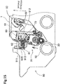
- Fig.15 illustrates the developing cartridge 1 in the separating operation.
- the driving force from the image forming apparatus changes the positions of the first columnar protrusion 46 and the second columnar protrusion 55.
- the lever of the drawer unit 90 presses each of the first columnar protrusion 46 and the second columnar protrusion 55, and each of the first columnar protrusion 46 and the second columnar protrusion 55 thus moves against the pressing force of the pressure member 93. Consequently, as shown by a dashed arrow illustrated in Fig. 15 , the casing 10 and the developing roller 30 of the developing cartridge 1 move in the second direction so as to separate away from the photosensitive drum 92.
- the IC chip assembly 60 is fixed in a state where the IC chip assembly 60 is nipped between the electric connector 913 and the second guide plate 912. Accordingly, the position of the IC chip assembly 60 is not changed relative to the drawer unit 90, when the casing 10 and the developing roller 30 move in the second direction so that the developing roller 30 is separated from the photosensitive drum 92. Further, the state of the coil spring 73 does not change from the second state. As a result, the position of the holder 62 relative to the casing 10 in the second direction changes from a standard position (first position) to a separation position (second position). The boss 621a then moves inside of the through-hole 451a in the second direction and the boss 621b then moves inside of the through-hole 451b in the second direction.
- the developing cartridge 1 can change the position of the casing 10 relative to the drawer unit 90 in the second direction, without changing the position of the electric contact surface 611 in the second direction relative to the drawer unit 90. Accordingly, the developing cartridge 1 can maintain the contacting state between the electric contact surface 611 and the electric connector 913 during the separating operation. The contacting state between the electric contact surface 611 and the electric connector 913 can also be maintained during the shipment of the image forming apparatus in which the developing cartridge 1 is attached to the drawer unit 90. Accordingly, abrasion or wear of the electric contact surface 611 can be suppressed.
- Fig. 16 is a partial exploded perspective view of the developing cartridge 1A according to a first modification.
- the first cover 45A includes a boss 451aA and a boss 451bA.
- the boss 451aA and the boss 451bA are arrayed in the second direction.
- Each of the boss 451aA and the boss 451bA extends from the first cover 45A toward the casing 10A in the third direction.
- the holder 62A has a through-hole 621A that penetrates the holder 62A in the third direction. Both of the boss 451aA and the boss 451bA are inserted in the through-hole 621A.
- the boss 451aA includes one edge of the boss 451aA and another edge of the boss 451aA in the second direction
- the boss 451bA includes one edge of the boss 451bA facing the another edge of the boss 451aA in the second direction and another edge of the boss 451bA in the second direction.
- the through-hole 621A has a dimension in the second direction greater than the distance between the one edge of the boss 451aA and the another edge of the boss 451bA in the second direction.
- the distance between the one edge of the boss 451aA and the another edge of the boss 451bA in the second direction is the longest distance the boss 451aA and the boss 451bA in the second direction, and the dimension of the through-hole 621A in the second direction is greater than the longest distance.
- the holder 62A can move together with the through-hole 621A in the second direction relative to both the casing 10A and the first cover 45A.
- the IC chip 61A having the electric contact surface 611A moves in the second direction together with the holder 62A.
- the dimension of the through-hole 621A in the first direction is greater than each dimension of the boss 451aA and the boss 451bA in the first direction. Accordingly, the holder 62A, can move together with the through-hole 621A in the first direction relative to both the casing 10A and the first cover 45A.
- the holder 62A moves in the first direction
- the IC chip 61A having the electric contact surface 611A moves in the first direction together with the holder 62A.
- the holder 62A may be movable in the third direction between the first cover 45A and the first outer surface 11A.
- the first cover 45A may include the boss 451Aa and boss 451bA, and the holder 62A may have the through-hole 621A, so that the electric contact surface 611 can move relative to the casing 10A in the first and second directions.
- the boss 451aA and the boss 451bA can be moved in the first direction inside of the through-hole 621A when the casing 10A is inclined in the first direction during the attachment of the developing cartridge 1A to the drawer unit 90.
- the boss 451aA and the boss 451bA can move in the second direction inside of the through-hole 621A.
- the position of the casing 10A can be changed in a state where the contact state of the electric contact surface 611A and the electric connecter is satisfactorily maintained.
- the number of the bosses may be one, or more than or equal to three.
- the number of the through-holes 621A formed on the holder 62A may be more than or equal to two.
- the holder 62A may have a recessed portion in which the boss 451aA and the boss 45bA can be inserted.
- the first outer surface of the casing may have a boss and the holder has the through-hole or the recessed portion through which the boss of the casing is inserted.
- Each of the boss 451aA and the boss 451bA may have either a cylindrical shape or a prism shape.
- Fig. 17 is a cross-sectional view of the IC chip assembly 60A indicated in Fig. 16 taken along a plane orthogonal to the third direction.
- the holder 62A of the IC chip assembly 60A includes a holder member 74A made of resin and a leaf spring 75A fixed to the holder member 74A.
- the holder member 74A includes a first end portion 740A that is positioned at one end portion of the holder 62A in the first direction.
- the IC chip 61A is fixed to the holding surface 620A that is portion of the outer surface of the first end portion 740A.
- the leaf spring 75A includes a second end portion 750A that is positioned at the another end portion of the holder 62A in the first direction.
- the first end portion 740A and the second end portion 750A are separated from each other in the first direction in the assembled holder 62A.
- the leaf spring 75A is made of a bent elastic metal plate, for example.
- the leaf spring 75A can be stretched or compressed in the first direction between a first state, and a second state in which the leaf spring 75A is bent more than in the first state.
- the length in the first direction of the leaf spring 75A in the first state is larger than the length in the first direction of the leaf spring 75A in the second state. That is, the distance in the first direction between the first end portion 740A and the second end portion 750A in the first state is longer than the distance in the first direction between the first end portion 740A and the second end portion 750A in the second state.
- the length in the first direction of the leaf spring 75A in the second state is smaller than the natural length of the leaf spring 75A.
- the leaf spring 75A may be used so that the IC chip assembly 60A can be stretched or compressed in the first direction. Further, as described above, the dimensional difference between the boss 451aA and the through-hole 621A, the dimensional difference between the boss 451bA and the through-hole 621A and stretch and compression of the leaf spring 75A enable the electric contact surface 611A to move in the first direction relative to the casing 10A, when the developing cartridge 1A is being attached to the drawer unit 90.
- Fig. 18 is a partial perspective view illustrating a developing cartridge 1B according to a second modification.
- the electric contact surface 611B of an IC chip 61B is oriented to face in the third direction.
- the first direction orthogonal to the electric contact surface 611B is the same direction as the third direction.
- a columnar elastic body 63B is positioned between a casing 10B and an IC chip assembly 60B.
- a coil spring extending in the first direction may be used.
- the columnar elastic body 63B includes one end portion in the third direction, and the one end portion is fixed to a holder 62B of the IC chip assembly 60B.
- the columnar elastic body 63B includes another end portion in the third direction, and the another end portion is fixed to a first outer surface of the casing 10B. That is, the casing 10B and the IC chip assembly 60B are connected to each other by the columnar elastic body 63B.
- Figs. 19 and 20 are explanatory diagrams illustrating movement of the IC chip assembly 60B in accordance with deformation of the columnar elastic body 63B.
- the columnar elastic body 63B is capable of being stretched or compressed in the first direction.
- the position of the electric contact surface 611B relative to the casing 10B in the first direction also changes.
- the columnar elastic body 63B can deform in a direction diagonal to the first direction.
- the position of the one end of the columnar elastic body 63B also changes relative to another end of the columnar elastic body 63B in a direction perpendicular to the first direction.
- Figs. 21 and 22 are explanatory diagrams illustrating how the developing cartridge 1B according to the second modification is attached to a drawer unit 90B.
- a first cover 45B includes a first frame portion 456B and a second frame portion 457B, and the first frame portion 456B and the second frame portion 457B are arranged with a gap between the first frame portion 456B and the second frame portion 457B in the second direction.
- the IC chip assembly 60B and the columnar elastic body 63B are accommodated in an accommodating portion 452B which defines a space between the first frame portion 456B and the second frame portion 457B.
- the first cover 45B further includes a pawl 453B protruding from the first frame portion 456B toward the accommodating portion 452B. As illustrated in Fig. 21 , before the developing cartridge 1B is attached to the drawer unit 90B, a portion of the IC chip assembly 60 is in contact with the pawl 453B. Hence, the columnar elastic body 63B is maintained in a more compressed state than the natural length of the columnar elastic body 63B in the first direction.
- Fig. 23 is an explanatory diagram illustrating a state where the separating operation is performed after the developing cartridge 1B is attached to the drawer unit 90B.
- the columnar elastic body 63B is deformed diagonally with respect to the first direction.
- the IC chip assembly 60B connected to the one end of the columnar elastic body 63B moves in the second direction relative to the casing 10B connected to the another end of the columnar elastic body 63B.
- the position of the casing 10B in the second direction can be changed without changing the position of the electric contact surface 611B in the second direction relative to the drawer unit 90B. That is, the separating operation can be performed in a state where the contact state between the electric contact surface 611B and the electric connector 913B is maintained.
- Fig. 24 is an exploded perspective view illustrating a first cover 45D and an IC chip assembly 60D of the developing cartridge according to a third modification.
- Fig. 25 is a cross-sectional view illustrating the first cover 45D and the IC chip assembly 60D.
- the electric contact surface 611D of the IC chip 61D are oriented to face in the third direction. Accordingly, the first direction orthogonal to the electric contact surfaces 611D is the same direction as the third direction.
- the IC chip assembly 60D includes the IC chip 61D, the holder 62D holding the IC chip 61D, and a joint member 63D.
- the holder 62D includes a plurality of pawls 622D, and each of the plurality of pawls 622D extends away from the electric contact surfaces 611D in the first direction.
- the holder 62D has four pawls 622D.
- the joint member 63D includes a fixing portion 631D fixed to the first cover 45D, and an arm 632D extending from the fixing portion 631D toward the holder 62D in the first direction.
- the arm 632D includes a distal end in the first direction, and a spherical portion 633D whose diameter is larger than a thickness of the arm 632D.
- the spherical portion 633D is positioned at the distal end of the arm 632D.
- the spherical portion 633D is held at a position inside of the holder 62D by the plurality of pawls 622D.
- the arm 632D and the holder 62D are connected to each other so as to be rotatable relative to each other. That is, the IC chip 61D and the holder 62D are rotatable relative to each other about the spherical portion 633D.
- the position of the electric contact surfaces 611D of the IC chip 61D relative to the fixing portion 631D can be moved in the second direction. Therefore, when the separating operation of the developing cartridge is performed, the casing and the first cover 45D can move in the second direction in a state where the contact state between the electric contact surfaces 611D of the IC chip 61D and the electric connector is maintained.
- the plurality of pawls 622D of the holder 62D and the arm 632D of the joint member 63D are movable relative to each other in the first direction.
- the IC chip 61D and the holder 62D can move relative to the fixing portion 631D in the first direction. Accordingly, the developing cartridge can be inserted, while the electric contact surfaces 611D of the IC chip 61D can be suppressed from being rubbed.
- an elastic member such as a coil spring 66D1 being stretched or compressed in the first direction is positioned between the fixing portion 631D of the joint member 63D and the plurality pawls 622D.
- coil spring 66D1 being stretched or compressed in the first direction is positioned between the first cover 45D and the plurality pawls 622D.
- the coil spring 66D1 shown in Fig. 25 extends through the circular opening in the first cover 45D, through which the arm 632D is extending. Accordingly, a repulsion force by coil spring 66D1 allows the electric contact surface 611D to reliably contact to the electric connector.
- Fig. 25 an elastic member such as a coil spring 66D1 being stretched or compressed in the first direction is positioned between the fixing portion 631D of the joint member 63D and the plurality pawls 622D.
- coil spring 66D1 being stretched or compressed in the first direction is positioned between the first cover 45D and the plurality pawls 622D.
- an elastic member such as a coil spring 66D2 being stretched or compressed in the third direction may not be positioned between the first cover 45D and the plurality pawls 622D.
- One end of the coil spring 66D2 contacts the fixing portion 631D, on the other hand, another end of the coil spring 662D contacts the first outer surface 11.
- the arm 632D may be rotatably connected to the fixing portion 631D or the first cover 45D.
- the arm 632D includes one spherical portion at one end of the arm 632D and another spherical portion at another end of the arm 632D. Either the one spherical portion or the another spherical portion may be rotatably held by a plurality of pawls of the first cover 45D. In this manner, when both ends of the arm 632D are rotatably connected, the position of the electric contact surface 611D in the second direction may be changed more flexibly.
- Fig. 27 is a partial perspective view of a developing cartridge 1E of the fourth modification.
- the holder 62E holding the IC chip 61E has a plate shape which has been deformed in a circular manner and whose ends are connected to each other.
- the holder 62E is made of a flexible resin, for example. Accordingly, in the embodiment shown in Fig. 27 , the holder 62E itself is an elastic member which is stretched or compressed in the first direction. With this structure, a distance between both ends of the holder 62E in the first direction is changeable. Accordingly, when the developing cartridge 1E is inserted into the drawer unit, abrasion or wear of the electric contact surface 611E of the IC chip 61E can be suppressed.
- the holder 62E is not necessary to be configured by a plurality of members due to stretch and compression of the holder 62E in the first direction.
- the holder 62E is not necessary to be comprised by an elastic member which is different from the member for holding the IC chip 61E.
- Fig. 28 is an exploded perspective view showing a first cover 45E and an IC chip assembly 60E of the fourth modification.
- the first cover 45E includes a boss 451aE extending in the third direction and a boss 451bE extending in the third direction.
- the boss 451aE and the boss 451bE are aligned in the second direction.
- the first cover 45E includes a connecting portion 455E which connects a top of the boss 451aE and a top of the boss 451bE to each other.
- the holder 62E extends in a ring shape surrounding the boss 451aE and the boss 451bE. And one pawl 623E positioned at one end of the holder 62E and another pawl 623E positioned at another end of the holder 62E are engaged with each other. Accordingly, a through-hole 621E is positioned at the inside of the holder 62E and the through-hole 621E penetrates through the holder 62E in the third direction.
- the boss 451aE and the boss 451bE are positioned inside of the through-hole 621E.
- the holder 62E further includes a plate portion 624E protruding from an inner surface of the holder 62E toward the through-hole 621E. The plate portion 624E is inserted between the boss 451aE and the boss 451bE.
- the distance between the boss 451aE and the boss 451bE in the second direction is greater than the thickness of the plate portion 624E in the second direction. Therefore, the holder 62E is able to relatively move together with the plate portion 624E with respect to the casing 10E and the first cover 45E in the second direction.
- the IC chip 61E having the electric contact surface 611E moves together with the holder 62E in the second direction.
- the size of the through-hole 621E in the first direction is greater than the sizes of each of the boss 451aE and the boss 451bE in the first direction. Therefore, the holder 62E is movable with respect to the casing 10E and the first cover 45E in the first direction. When the holder 62E moves in the first direction, the IC chip 61E having the electric contact surface 611E moves together with the holder 62E in the first direction.
- the holder 62E When the developing cartridge 1E is attached to the drawer unit, the holder 62E is nipped by the guide plates of the drawer unit and the holder 62E is compressed in the first direction. Specifically, by approaching both of the one pawl 623E and the another pawl 623E to each other, an urging force exerting in the direction to separate the both of the one pawl 623E and the another pawl 623E from each other is generated.
- the electric contact surface 611E of the IC chip 61E is in contact with the electric connector in a state where the holder 62E is elastically deformed.
- the electric contact surface 611E is fixed to the electric connector due to the urging force in a state where the electric contact surface 611E is in contact with the electric connector.
- the casing 10E moves in the second direction in a state where the contact between the electric contact surface 611E and the electric connector is maintained.
- the boss 451aE and the boss 451bE are able to move in the first direction inside the through-hole 621E.
- the boss 451aE and the boss 451bE are able to move in the second direction inside the through-hole 621E.
- the position of the casing 10E can be changed in a state where the contact condition between the electric contact surface 611E and the electric connector is maintained in a good manner.
- the number of the bosses provided at the first cover 45E may be one, two, three or more than three.
- Fig. 29 is a perspective view showing a developing cartridge 1F and a drum cartridge 80F of the fifth modification.
- the developing cartridge 1F shown in Fig. 29 includes a casing 10F, a developing roller 30F, an IC chip assembly 60F, and a first cover 45F.
- the developing cartridge 1F is attached to the drum cartridge 80F instead of the drawer unit.
- the drum cartridge 80F includes one developing cartridge holding portion 81F holding the developing cartridge 1F.
- the developing cartridge holding portion 81F includes a photosensitive drum 82F.
- Fig. 30 is a view showing how to attach the drum cartridge 80F to an image forming apparatus 100F in a state where the developing cartridge 1F is attached to the drum cartridge 80F.
- the drum cartridge 80F is attached to a drum cartridge holding portion 101F provided in the image forming apparatus 100F in a state where the developing cartridge 1F is attached to the drum cartridge 80F.
- FIG. 31 is an exploded perspective view showing a detail of the IC chip assembly 60F of the developing cartridge 1F.
- the IC chip assembly 60F of the developing cartridge 1F includes an IC chip 61F as a storage medium and a holder 62F holding the IC chip 61F.
- the first cover holds the holder 62F at a side of the casing 10F in the third direction.
- the holder 62F includes a first holder member 71F, a second holder member 72F, and a coil spring 73F.
- the first holder member 71F includes a first end portion of the holder 62F similar to the first end portion 710 of the holder 62
- the second holder member 72F includes a second end portion of the holder 62F similar to the second end portion 720 of the holder 62.
- the coil spring 73F is an elastic member that can be stretched or compressed in the first direction.
- the first holder member 71F includes a boss 621aF, a boss 621bF, and a boss 621cF.
- the boss 621aF extends in the third direction toward the first cover 45F from a certain surface of the first holder member 71F, and the certain surface faces the first cover 45F.
- the first cover 45F has a through-hole 451F.
- the through-hole 451F penetrates through the first cover 45F in the third direction.
- the boss 621aF is inserted through the through-hole 451F.
- each of the boss 621bF and the boss 621cF extends in the third direction toward the casing 10F from a certain surface of the first holder member 71F, and the certain surface faces casing 10F.
- the casing 10F includes a recessed portion 15aF and a recessed portion 15bF.
- Each of the recessed portion 15aF and the recessed portion 15bF is recessed from the first outer surface 11F of the casing 10F in the third direction.
- the boss 621bF is inserted through the recessed portion 15aF.
- the boss 621cF is inserted through the recessed portion 15bF.
- the through-hole 451F has a size (inner dimension) in the second direction greater than a size (outer dimension) of the boss 621aF in the second direction.
- the recessed portion 15aF has a size (inner dimension) in the second direction greater than a size (outer dimension) of the boss 621bF in the second direction.
- the recessed portion 15bF has a size (inner dimension) in the second direction greater than a size (outer dimension) of the boss 621cF in the second direction.
- the holder 62F can move in the second direction relative to the casing 10F and the first cover 45F, together with the bosses 621aF, 621bF, and 621cF.
- the IC chip 61F including the electric contact surface 611F also moves in the second direction, together with the holder 62F.
- the through-hole 451F has a size (inner dimension) in the first direction greater than a size (outer dimension) of the boss 621aF in the first direction.
- the recessed portion 15aF has a size (inner dimension) in the first direction greater than a size (outer dimension) of the boss 621bF in the first direction.
- the recessed portion 15bF has a size (inner dimension) in the first direction greater than a size (outer dimension) of the boss 621cF in the first direction.
- the holder 62F can move in the first direction relative to the casing 10F and the first cover 45F, together with the boss 621aF, boss 621bF, and boss 621cF.
- the IC chip 61F including the electric contact surface 611F also moves in the first direction, together with the holder 62F.
- the second holder member 72F includes a recess portion 625F.
- the drum cartridge 80F includes a convex portion 83F.
- the recess portion 625F and the convex portion 83F face each other in the first direction.
- the size of the recess portion 625F gradually enlarges while progressing away from the IC chip 61F in the first direction.
- the size of the convex portion 83F gradually diminishes while progressing toward a top of the convex portion 83F in the first direction.
- the image forming apparatus 100F includes an electric connector 102F.
- the first holder member 71F is brought into contact with a component of the image forming apparatus 100F.
- the convex portion 83F of the drum cartridge 80F is fitted in the recess portion 625F of the second holder member 72F. Therefore, the position of the second holder member 72F relative to the drum cartridge 80f is fixed.
- the holder 62F is nipped between the component of the image forming apparatus 100F and the drum cartridge 80F, whereby the coil spring 73F is compressed in the first direction.
- the electric contact surfaces 611F of the IC chip 61F are brought into contact with the one or more of electric connectors 102F.
- the IC chip 61F is brought into contact with the electric connector 102F, while receiving a repulsion force from the coil spring 73F.
- the holder 62F is nipped between the electric connector 102F and the convex portion 83F. In this way, the holder 62F is positioned relative to the image forming apparatus 100F and the drum cartridge 80F.
- the second holder member 72F includes a pawl 714F.
- the pawl 714F protrudes from the second holder member 72F in a direction that crosses the first direction.
- the pawl 714F protrudes in the third direction from the second holder member 72F.
- the first holder member 71F has an opening 721F. The pawl 714F is inserted through the opening 721F. This prevents the first holder member 71F from being detached from the second holder member 72F.
- the casing 10F of the developing cartridge 1F includes a first rib 46F and a second rib 55F.
- the first rib 46F protrudes from the first outer surface 11F in the third direction.
- the second rib 55F protrudes from the second outer surface 12F in the third direction.
- the drum cartridge 80F includes a first lever 84F and a second lever 85F.
- the first lever 84F and second lever 85F are operated by a driving force supplied from the image forming apparatus, whereupon the first rib 46F is pushed by the first lever 84F and the second rib 55F is pushed by the second lever 85F.
- This operation changes the positions of the first rib 46F and second rib 55F.
- the casing 10F of the developing cartridge 1F and the developing roller 30F move in the second direction and move away from the photosensitive drum 92.
- the position of the holder 62F can be changed in the second direction relative to the casing 10F. Accordingly, the position of the casing 10F in the second direction can be changed, while the positions of the electric contact surface 611F relative to the electric connector 102F in the second direction being maintained, that is, the positions of the electric contact surface 611F relative to the electric connector 102F in the second direction being unchanged. Therefore, it is possible to perform the separating operation, while maintaining the electric contact surface 611F and electric connector 102F in contact with each other. Accordingly, abrasion or wear of the electric contact surface 611F can be suppressed.
- the electric contact surfaces 611F are movable relative to the casing 10F in the first direction. Accordingly, when the drum cartridge 80F is attached to the image forming apparatus 100F, abrasion or wear of the electric contact surface 611F can be suppressed.
- the IC chip including the electric contact surfaces is fixed to the outer surface of the holder.
- the electric contact surfaces of the IC chip that serve to contact the electric connectors may be fixed to the outer surface of the holder, but portions of the IC chip other than the electric contact surfaces may be positioned at other portions of the developing cartridge.
- the plural gears provided within each of the first gear portion and the second gear portion are engaged with one another through meshing engagement of the gear teeth.
- the plural gears provided within each of the first gear portion and the second gear portion may be engaged with one another through a frictional force.
- frictional members such as rubber members, may be provided to the outer circumferences of two gears that engage with each other.
- the developing cartridge can be attached to the drawer unit of the image forming apparatus.
- the developing cartridge may be attached to the image forming apparatus which does not include the drawer unit.
- Shapes of the details in the developing cartridge may differ from those shown in the drawings attached to this application.
- the respective components employed in the above-described embodiment and modifications can be selectively combined together within an appropriate range so that no inconsistency will arise.
Description
- The present invention relates to a developing cartridge and to an image forming apparatus including the same.
- An electro-photographic type image forming apparatus such as a laser printer and an LED printer is known. A developing cartridge is used in the image forming apparatus. The developing cartridge includes a developing roller for supplying toner.
Patent publication 1 discloses a developing cartridge which is capable of being attached to a drawer unit. The drawer unit is positioned in an interior of the image forming apparatus and can be pulled from the inside of the image forming apparatus to the outside of the image forming apparatus. The drawer unit includes a photosensitive drum. The photosensitive drum faces the developing roller when the developing cartridge is attached to the drawer unit. - Further, Patent publication 2 discloses a developing cartridge is capable of being attached to a drum cartridge. The drum cartridge includes a photosensitive drum. The photosensitive drum faces the developing roller when the developing cartridge is attached to the drum cartridge. When the developing cartridge is attached to the drum cartridge, the photosensitive drum faces a developing roller of the developing cartridge. The developing cartridge is attached to the image forming apparatus in a state where the developing cartridge is attached to the drum cartridge.
-
- [Patent publication 1] Japanese Patent Application Publication No.
2011-59510 - [Patent publication 2] Japanese Patent Application Publication No.
2013-54058 - Further, a developing cartridge including a storage medium is also known. An IC (Integrated Circuit) chip is an example of the storage medium. The storage medium has an electric contact surface. The electric contact surface is in contact with an electric connector of the image forming apparatus or the drawer unit in a state where the developing cartridge is attached to the image forming apparats or drawer unit. However, friction between the electric contact surface and, for example, a protrusion of the image forming apparatus or the drawer unit may occur when the developing cartridge is attached to the image forming apparatus or the drawer unit.
- It is an object of the present invention to reduce friction between the electric contact surface of the developing cartridge and, for example, the protrusion of the image forming apparatus or the drawer unit.
- The object of the invention is attained by a developing cartridge according to
claim 1. Further developments of the invention are specified in the dependent claims. According to the invention, a developing cartridge comprises: a casing configured to accommodate developer therein; a storage medium including an electric contact surface; an elastic member extending in a first direction which crosses the electric contact surface, the elastic member configured to be compressed or stretched in the first direction between a first state and a second state; a holder including an outer surface being positioned toward a side of the holder in the first direction, the electric contact surface being positioned at the outer surface, the electric contact surface being movable between a first position and a second position in the first direction relative to the casing; wherein a length of the elastic member in the first direction is greater in the first state than in the second state, wherein the electric contact surface is in the first position in a state where the elastic member is in the first state, and wherein the electric contact surface is in the second position in a state where the elastic member is in the second state. - In the invention, friction between the electric contact surface and, for example, the image forming apparatus or the drawer unit can be reduced when the developing cartridge is attached to, for example, the image forming apparatus or the drawer unit.
- In a first preferred embodiment as defined in claim 2, the holder includes a first end portion including the outer surface and a second end portion being separate from the first end portion in the first direction, and the elastic member is positioned between the first end portion and the second end portion.
- In the first preferred embodiment, the first end portion including the outer surface is movable in the first direction relative to the second end portion, because the elastic member is positioned between the first end portion and the second end portion. Therefore, friction between the electric contact surface and, for example, the image forming apparatus or the drawer unit can be reduced when the developing cartridge is attached to, for example, the image forming apparatus or the drawer unit.
- In a second preferred embodiment as defined in claim 3, a distance between the first end portion and the second end portion in the first direction is greater in the first state than in the second state.
- In the second preferred embodiment, a distance between the first end portion and the second end portion in the first direction is greater in the first state than in the second state. Accordingly, a distance between the first end portion including the outer surface and the second end portion is changeable. Therefore, friction between the electric contact surface and, for example, the image forming apparatus or the drawer unit can be reduced when the developing cartridge is attached to, for example, the image forming apparatus or the drawer unit.
- In a third preferred embodiment as defined in claim 4, the electric contact surface is movable relative to the casing to any one of the first position, the second position and a third position in the first direction, the elastic member is configured to be compressed or stretched in the first direction to be in any one of the first state, the second state and a third state, the length of the elastic member in the first direction is greater in the third state than in the second state, and the electric contact surface is in the third position in a state where the elastic member is in the third state.
- In the third preferred embodiment, a position of the electric contact surface is further changeable in the first direction between the second position and the third position. Therefore, friction between the electric contact surface and, for example, the image forming apparatus or the drawer unit can be reduced when the developing cartridge is attached to, for example, the image forming apparatus or the drawer unit.
- In a fourth preferred embodiment as defined in claim 5, the electric contact surface is movable relative to the casing to any one of the first position, the second position and a third position, the elastic member is configured to be compressed or stretched in the first direction to be in any one of the first state, the second state and a third state, the length of the elastic member in the first direction is greater in the third state than in the second state, and the distance between the first end portion and the second end portion in the first direction is greater in the third state than in the second state, and the electric contact surface is in the third position in a state where the elastic member is in the third state.
- In the fourth preferred embodiment, the first end portion including the electric contact surface is movable in the first direction relative to the second end portion, because the elastic member is positioned between the first end portion and the second end portion, and additionally, a position of the electric contact surface is further changeable in the first direction between the second position and the third position. Therefore, friction between the electric contact surface and, for example, the image forming apparatus or the drawer unit can be reduced when the developing cartridge is attached to, for example, the image forming apparatus or the drawer unit.
- In a fifth preferred embodiment as defined in claim 6, the electric contact surface relative to the casing is movable between the first position and the second position according to attachment of the developing cartridge to an image forming apparatus, both of a portion of the holder and the electric contact surface is not in contact with a portion of the image forming apparatus in a state where the electric contact surface is in the first position, and at least one of a portion of the holder and the electric contact surface is in contact with a portion of the image forming apparatus in a state where the electric contact surface is in the second position.
- In the fifth preferred embodiment, if the holder can be in contact with a portion of the image forming apparatus, friction between the electric contact surface and, for example, the image forming apparatus or the drawer unit can be reduced, because the holder is movable from the first position to the second position.
- In a sixth preferred embodiment as defined in claim 7, the position of the electric contact surface relative to the casing is movable between the first position and the third position through the second position according to attachment of the developing cartridge to the image forming apparatus, both of a portion of the holder and the electric contact surface is not in contact with a portion of the image forming apparatus in a state where the electric contact surface is in the first position, at least one of a portion of the holder and the electric contact surface is in contact with a portion of the image forming apparatus in a state where the electric contact surface is in the second position, and the electric contact surface is in contact with an electrical connector of the image forming apparatus in a state where the electric contact surface is in the third position.
- In the sixth preferred embodiment, a position of the electric contact surface is further changeable in the first direction from the second position to the third position, furthermore, the electric contact surface is in contact with the electrical connector of the image forming apparatus in the third position. Therefore, friction between the electric contact surface and, for example, the image forming apparatus or the drawer unit can be reduced, because the holder is movable from the first position to the second position, and the electric contact surface can be in contact with the electrical connector of the image forming apparatus.
- In a seventh preferred embodiment as defined in claim 8, the length of the elastic member in the first direction in the third state is shorter than a natural length of the elastic member.
- In the seventh preferred embodiment, the electric contact surface can receive a repulsion force by the elastic member, because a length of the elastic member in the first direction in the third state is shorter than a natural length of the elastic member.
- In an eight preferred embodiment as defined in claim 9, the outer surface includes: a first surface inclined relative to the electric contact surface, the first surface being positioned at one side of the electric contact surface in a second direction which is different from the first direction.
- In a ninth preferred embodiment as defined in
claim 10, the developing cartridge further comprises: a developing roller rotatable about an axis extending in a third direction which is different from the first direction, the developing roller being positioned at one side of the casing in the second direction. - In a tenth preferred embodiment as defined in
claim 11, the first surface extends from a third position to a fourth position toward the electric contact surface, and the third position is farther from the electric contact surface in the first direction than the fourth position. Therein, a distance between the third position and the fourth position in the first direction may be greater than a distance between the electric contact surface and the fourth position in the first direction. - In each one of the eighth to tenth preferred embodiment, the developing cartridge includes the first surface inclined relative to the electric contact surface. Therefore, the holder can be guided by the first surface, when the developing cartridge is attached to or detached from, for example, the image forming apparatus or the drawer unit.
- In a eleventh preferred embodiment as defined in
claim 12, the first surface is a first guide surface, the first guide surface is contactable with a portion of an image forming apparatus when the developing cartridge is attached to the image forming apparatus. - In the eleventh preferred embodiment, the developing cartridge includes the first guide surface inclined relative to the electric contact surface. Therefore, the holder can be guided by the first guide surface, when the developing cartridge is attached to or detached from, for example, the image forming apparatus or the drawer unit.
- In a twelfth preferred embodiment as defined in
claim 13, the outer surface includes: a second surface inclined relative to the electric contact surface, the second surface being positioned at another side of the electric contact surface in the second direction. - In a thirteenth preferred embodiment as defined in
claim 14, the second surface extends from a fifth position to a sixth position toward the electric contact surface, and the fifth position is farther from the electric contact surface in the first direction than the sixth position. Therein, a distance between the fifth position and the sixth position in the first direction may be greater than a distance between the electric contact surface and the sixth position in the first direction. - In each one of the twelfth and thirteenth preferred embodiment, the developing cartridge includes the second surface inclined relative to the electric contact surface. Therefore, the holder can be guided by the second surface, when the developing cartridge is attached to or detached from, for example, the image forming apparatus or the drawer unit.
- In a fourteenth preferred embodiment as defined in
claim 15, the second surface is a second guide surface, the second guide surface is contactable with a portion of an image forming apparatus when the developing cartridge is attached to the image forming apparatus. - In the fourteenth preferred embodiment, the developing cartridge includes the second guide surface inclined relative to the electric contact surface. Therefore, the holder can be guided by the second guide surface, when the developing cartridge is attached to or detached from, for example, the image forming apparatus or the drawer unit.
- In a fifteenth preferred embodiment as defined in claim 16, the outer surface includes: a third surface positioned at both sides of the electric contact surface in a third direction which is different from the first direction respectively, and the third surface is farther from the elastic member in the first direction than the electric contact surface.
- In the fifteenth preferred embodiment, the developing cartridge includes the third surface inclined relative to the electric contact surface. Therefore, the holder can be guided by the third surface, when the developing cartridge is attached to or detached from, for example, the image forming apparatus or the drawer unit.
- In a sixteenth preferred embodiment as defined in claim 17, the third surface is a third guide surface, the third guide surface is contactable with a portion of an image forming apparatus when the developing cartridge is attached to the image forming apparatus.
- In the sixteenth preferred embodiment, the developing cartridge includes the third guide surface inclined relative to the electric contact surface. Therefore, the holder can be guided by the third guide surface, when the developing cartridge is attached to or detached from, for example, the image forming apparatus or the drawer unit.
- In any embodiment discussed above, the first direction may be perpendicular to the electric contact surface.
- In any embodiment discussed above, the holder may be movable with the storage medium. Throughout the description, if a first element is described to be movable with a second element, then this means that there is a fixed relative position and a fixed orientation between the first and second element.
- In any embodiment discussed above, the holder may hold the electric contact surface at the outer surface.
- In any embodiment discussed above, the storage medium may be positioned at the outer surface of the holder. Therein, the holder may hold the storage medium at the outer surface.
- In any embodiment discussed above, the developing cartridge may further comprise a developing roller rotatable about an axis extending in a direction which is different from the first direction.
- In any embodiment discussed above, the holder may be positioned at a side of the casing.
- In any embodiment discussed above, the elastic member may be a spring. Therein, the spring may be a coil spring.
- The object of the invention is also attained by an image forming apparatus comprising: a developing cartridge holding portion; a developing cartridge according to the invention as defined in any one
claims 1 to 5, wherein the developing cartridge is configured to be removably attached to the cartridge holding portion, the position of the electric contact surface relative to the casing is movable between the first position and the second position according to attachment of the developing cartridge to the developing cartridge holding portion of the image forming apparatus, wherein both of a portion of the holder and the electric contact surface is not in contact with a portion of the image forming apparatus in a state where the electric contact surface is in the first position, and wherein at least one of a portion of the holder and the electric contact surface is in contact with a portion of the image forming apparatus in a state where the electric contact surface is in the second position. - The object of the invention is also attained by an image forming apparatus comprising a developing cartridge holding portion; the developing cartridge of the invention as defined in claim 4 or 5, wherein the position of the electric contact surface relative to the casing is movable between the first position and the third position through the second position according to attachment of the developing cartridge to the developing cartridge holding portion of the image forming apparatus, wherein both of a portion of the holder and the electric contact surface is not in contact with a portion of the image forming apparatus in a state where the electric contact surface is in the first position, at least one of a portion of the holder and the electric contact surface is in contact with a portion of the image forming apparatus in a state where the electric contact surface is in the second position, and the electric contact surface is in contact with an electrical connector of the image forming apparatus in a state where the electric contact surface is in the third position.
- In any one of the above described image forming apparatuses, the developing cartridge may be the developing cartridge of the invention as defined in claims 9 to 11, wherein the first surface is a first guide surface, the first guide surface being contactable with a portion of an image forming apparatus when the developing cartridge is attached to the developing cartridge holding portion of the image forming apparatus.
- In any one of the above described image forming apparatuses the developing cartridge may be the developing cartridge of the invention as defined in
claim -
-
Fig. 1 is a perspective view of a developing cartridge; -
Fig. 2 is a perspective view of the developing cartridge; -
Fig. 3 is a perspective view of the developing cartridge; -
Fig. 4 is a perspective view of the developing cartridge; -
Fig. 5 is a perspective view of the developing cartridge; -
Fig. 6 is an exploded perspective view of an IC (Integrated Circuit) chip assembly; -
Fig. 7 is a cross-sectional view of the IC chip assembly; -
Fig. 8 is a view for description of an attachment of the developing cartridge; -
Fig. 9 is a view for description of the attachment of the developing cartridge; -
Fig. 10 is a view for description of the attachment of the developing cartridge; -
Fig. 11 is a view for description of the attachment of the developing cartridge; -
Fig. 12 is a view for description of the attachment of the developing cartridge; -
Fig. 13 is a view for description of the attachment of the developing cartridge; -
Fig. 14 is a view for description of the attachment of the developing cartridge; -
Fig. 15 is a view for description of a separating operation; -
Fig. 16 is a partial exploded perspective view of a developing cartridge according to a first modification; -
Fig. 17 is a cross-sectional view of an IC (Integrated Circuit) chip assembly according to the first modification; -
Fig. 18 is a partial perspective view of a developing cartridge according to a second modification; -
Fig. 19 is a view for description of operation of a columnar like resilient member and an IC chip assembly according to the second modification; -
Fig. 20 is a view for description of operation of the columnar like resilient member and the IC chip assembly according to the second modification; -
Fig. 21 is a view for description of an assembly of a developing cartridge according to the second modification; -
Fig. 22 is a view for description of the assembly of the developing cartridge according to the second modification; -
Fig. 23 is a view for description of a separating operation in the developing cartridge according to the second modification; -
Fig. 24 is an exploded perspective view of a first cover and an IC (Integrated Circuit) chip assembly according to a third modification; -
Fig. 25 is a cross-sectional view of the first cover and the IC chip assembly according to the third modification; -
Fig. 26 is a perspective view of the IC chip assembly according to the third modification; -
Fig. 27 is a partial perspective view of a developing cartridge according to a fourth modification; -
Fig. 28 is an exploded perspective view of the first cover and the IC chip assembly according to the fourth modification; -
Fig. 29 is a perspective view of a developing cartridge and a drum cartridge according to a fifth modification; -
Fig. 30 is a view for description of attachment of the drum cartridge to an image forming apparatus according to the fifth modification; -
Fig. 31 is an exploded perspective view of the IC chip assembly and components ambient thereto according to the fifth modification; and -
Fig. 32 is a cross-sectional view of the first cover, the IC chip assembly and an elastic member according to the third modification. - A preferred embodiment of the present invention will be described with reference to drawings.
- In the following embodiment, a direction which crosses an electric contact surface of an IC chip (in the following embodiment, more preferably, a direction which is perpendicular to the electric contact surface of the IC chip) will be referred to as "first direction", and a moving direction of a casing in a separating operation will be referred to as "second direction". And an extending direction of a rotation axis of a developing roller will be referred to as "third direction".
-
Figs. 1 to 5 are perspective views of a developingcartridge 1. The developingcartridge 1 is used for an electro-photographic type image forming apparatus (for example, a laser printer or a LED printer), and is a unit for supplying developer (toner, for example) to a photosensitive drum. As shown inFig. 1 , the developingcartridge 1 is attached to adrawer unit 90 of the image forming apparatus. When the developingcartridge 1 is replaced, thedrawer unit 90 is drawn out from a front surface of the image forming apparatus. Thedrawer unit 90 includes fourcartridge holding portions 91, and the developingcartridge 1 is attached to fourcartridge holding portions 91, respectively. Each of fourcartridge holding portions 91 includes a photosensitive drum. - In the present embodiment, four developing
cartridges 1 are attached to onedrawer unit 90. Each of the four developingcartridges 1 is configured to accommodate developer therein, and the color of the developer is different colors (cyan, magenta, yellow, and black, for example) among the four developing cartridges respectively. However, the number of the developingcartridges 1 that can be attached to thedrawer unit 90 may be 1 to 3 or be greater than or equal to 5. - As shown in
Figs. 2 to 5 , each developingcartridge 1 according to the present embodiment includes acasing 10, anagitator 20, a developingroller 30, afirst gear portion 40, asecond gear portion 50, and an IC (Integrated Circuit)chip assembly 60. - The developing
roller 30 is a roller rotatable about a rotation axis extending in the third direction. The developingroller 30 according to the present embodiment includes aroller body 31 and aroller shaft 32. Theroller body 31 is a cylinder-shaped member extending in the third direction. Theroller body 31 is made of an elastic rubber, for example. Theroller shaft 32 is a cylindrical member penetrating through theroller body 31 in the third direction. Theroller shaft 32 is made of metal or conductive resin. - The
roller shaft 32 may not penetrate through theroller body 31 in the third direction. For example, each of a pair ofroller shafts 32 may extend from each end of theroller body 31 in the third direction. - The
agitator 20 includes anagitator shaft 21 and anagitation blade 22. Theagitator shaft 21 extends along the rotation axis extending in the third direction. Theagitation blade 22 expands outward from theagitator shaft 21 in a radial direction. Theagitation blade 22 is positioned inside a developingchamber 13 of thecasing 10. Afirst agitator gear 44 and asecond agitator gear 51 described later are mounted to both end portions in the third direction of theagitator shaft 21, respectively. Accordingly, theagitator shaft 21 and theagitation blade 22 are rotatable with thefirst agitator gear 44 and thesecond agitator gear 51. The developer which is accommodated in the developingchamber 13 is agitated by rotation of theagitation blade 22. Instead of theagitation blade 22, the agitator may include an agitation film. - The
casing 10 is a case configured to accommodate therein developer (toner, for example) for an electro-photographic printing. Thecasing 10 includes a firstouter surface 11 and a secondouter surface 12. The firstouter surface 11 and the secondouter surface 12 are separated from each other in the third direction. Thefirst gear portion 40 and theIC chip assembly 60 are positioned at the firstouter surface 11. Thesecond gear portion 50 is positioned at the secondouter surface 12. Thecasing 10 extends in the third direction from the firstouter surface 11 to the secondouter surface 12. The developingchamber 13 for accommodating the developer is provided in thecasing 10. - The
casing 10 has anopening 14. Theopening 14 communicates between the developingchamber 13 and an exterior of the developingchamber 13. Theopening 14 is positioned at one end portion in the second direction of thecasing 10. The developingroller 30 is positioned at the opening14. That is, the developingroller 30 is positioned closer to one side of thecasing 10 than to the center of thecasing 10 in the second direction. Theroller body 31 is fixed to theroller shaft 32 so as to be incapable of rotating relative to theroller shaft 32. One end portion of theroller shaft 32 in the third direction is mounted to a developinggear 42 described later so as to be incapable of rotating relative to the developinggear 42. When the developinggear 42 rotates, theroller shaft 32 rotates with the developinggear 42 and then theroller body 31 rotates together with theroller shaft 32. - When the developing
cartridge 1 receives a driving force, the developer is supplied from the developingchamber 13 in thecasing 10 onto an outer peripheral surface of the developingroller 30 via a supply roller (omitted in the figure). At this time, the developer is tribocharged between the supply roller and the developingroller 30. On the other hand, bias voltage is applied to theroller shaft 32 of the developingroller 30. Accordingly, static electricity between theroller shaft 32 and the developer moves the developer toward the outer peripheral surface of theroller body 31. - The developing
cartridge 1 further includes a layer thickness regulation blade which is omitted in the figure. The layer thickness regulation blade regulates a thin layer of the developer supplied onto the outer peripheral surface of theroller body 31 so that the thickness of the developer becomes constant. Then, the developer on the outer peripheral surface of theroller body 31 is supplied to the photosensitive drum of thedrawer unit 90. At this time, the developer moves from theroller body 31 to the photosensitive drum on the basis of an electrostatic latent image formed on the outer peripheral surface of the photosensitive drum. Accordingly, the electrostatic latent image is visualized on the outer peripheral surface of the photosensitive drum. - The
first gear portion 40 is positioned at one end portion in the third direction of thecasing 10. That is, thefirst gear portion 40 is positioned at the firstouter surface 11.Fig. 4 is a perspective view of the developingcartridge 1 in a state in which thefirst gear portion 40 is disassembled. As shown inFig. 4 , thefirst gear portion 40 includes acoupling 41, a developinggear 42, anidle gear 43, afirst agitator gear 44, and afirst cover 45. A plurality of gear teeth of each gear are not illustrated inFig. 4 . - The
coupling 41 is a gear for initially receiving the driving force applied from the image forming apparatus. Thecoupling 41 is rotatable about a rotation axis extending in the third direction. Thecoupling 41 includes acoupling portion 411 and acoupling gear 412. Thecoupling portion 411 and thecoupling gear 412 are integral with each other and made of a resin, for example. Thecoupling portion 411 has acoupling hole 413 depressed in the third direction. Thecoupling gear 412 includes a plurality of gear teeth. The plurality of gear teeth are provided on an entire of an outer peripheral surface of thecoupling gear 412 at equal intervals. - When the
drawer unit 90 to which the developingcartridge 1 is attached is accommodated in the image forming apparatus, a drive shaft of the image forming apparatus is inserted into thecoupling hole 413 of thecoupling portion 411. With this configuration, the drive shaft and thecoupling portion 411 are connected so as to be incapable of rotating relative to each other. Accordingly, thecoupling portion 411 rotates when the drive shaft rotates, and thecoupling gear 412 rotates together with thecoupling portion 411. - The developing
gear 42 is a gear for rotating the developingroller 30. The developinggear 42 is rotatable about a rotation axis extending in the third direction. The developinggear 42 includes a plurality of gear teeth. The plurality of gear teeth are provided on an entire of an outer peripheral surface of the developinggear 42 at equal intervals. At least a portion of the plurality of gear teeth of thecoupling gear 412 meshes with at least a portion of the plurality of gear teeth of the developinggear 42. Further, the developinggear 42 is mounted to the end portion of theroller shaft 32 in the third direction so as to be incapable of rotating relative to theroller shaft 32. With this construction, when thecoupling gear 412 rotates, the developinggear 42 rotates with thecoupling gear 412 and the developingroller 30 also rotates with the developinggear 42. - The
idle gear 43 is a gear for transmitting rotational driving force of thecoupling gear 412 to thefirst agitator gear 44. Theidle gear 43 is rotatable about a rotation axis extending in the third direction. Theidle gear 43 includes a largediameter gear portion 431 and a smalldiameter gear portion 432. The largediameter gear portion 431 and the smalldiameter gear portion 432 are arranged in the third direction. The smalldiameter gear portion 432 is positioned between the largediameter gear portion 431 and the firstouter surface 11 of thecasing 10. In other words, the largediameter gear portion 431 is farther away from the firstouter surface 11 than the smalldiameter gear portion 432 is. A diameter of the smalldiameter gear portion 432 is smaller than a diameter of the largediameter gear portion 431. In other words, a diameter of an addendum circle of the smalldiameter gear portion 432 is smaller than a diameter of an addendum circle of the largediameter gear portion 431. The largediameter gear portion 431 and the smalldiameter gear portion 432 are integral with each other and are made of a resin. - The large
diameter gear portion 431 includes a plurality of gear teeth, and the plurality of gear teeth are provided on an entire of an outer peripheral surface of the largediameter gear portion 431 at equal intervals. The smalldiameter gear portion 432 includes a plurality of gear teeth, and the plurality of gear teeth are provided on an entire of an outer peripheral surface of the smalldiameter gear portion 432 at equal intervals. The number of gear teeth of the smalldiameter gear portion 432 is less than the number of gear teeth of the largediameter gear portion 431. At least a portion of the plurality of gear teeth of thecoupling gear 412 meshes with at least a portion of the plurality of gear teeth of the largediameter gear portion 431. Further, at least a portion of the plurality of gear teeth of the smalldiameter gear portion 432 meshes with at least a portion of the plurality of gear teeth of thefirst agitator gear 44. When thecoupling gear 412 rotates, the largediameter gear portion 431 rotates together with thecoupling gear 412 and the smalldiameter gear portion 432 rotates together with the largediameter gear portion 431. Also, thefirst agitator gear 44 rotates with the rotation of the smalldiameter gear portion 432. - The
first agitator gear 44 is a gear for rotating theagitator 20 in the developingchamber 13. Thefirst agitator gear 44 is rotatable about a rotation axis extending in the third direction. Thefirst agitator gear 44 includes a plurality of gear teeth, and the plurality of gear teeth are provided on an entire of an outer peripheral surface of thefirst agitator gear 44 at equal intervals. As described above, at least a portion of the plurality of gear teeth of the smalldiameter gear portion 432 meshes with the at least a portion of the plurality of gear teeth of thefirst agitator gear 44. Further, thefirst agitator gear 44 is mounted to one end portion of theagitator shaft 21 in the third direction so as to be incapable of rotating relative to theagitator shaft 21. With the configuration, when the rotational driving force is transmitted from thecoupling 41 to thefirst agitator gear 44 via theidle gear 43, thefirst agitator gear 44 rotates and theagitator 20 rotates together with thefirst agitator gear 44. - The
first cover 45 is fixed to the firstouter surface 11 of thecasing 10 by screws, for example. Thecoupling gear 412, the developinggear 42, theidle gear 43, and thefirst agitator gear 44 are accommodated in a space between the firstouter surface 11 and thefirst cover 45. Thecoupling hole 413 of thecoupling portion 411 is exposed to an outside of thefirst cover 45. Thefirst cover 45 according to the present embodiment also serves as a holder cover for holding theholder 62 of theIC chip assembly 60 described later. A structure of thefirst cover 45 as the holder cover will be described later in detail. - The
second gear portion 50 is positioned at the other end portion of thecasing 10 in the third direction. In other words, thesecond gear portion 50 is positioned at the secondouter surface 12.Fig. 5 is a perspective view of the developingcartridge 1 in which thesecond gear portion 50 is exploded. As illustrated inFig. 5 , thesecond gear portion 50 includes asecond agitator gear 51, adetection gear 52, an electricallyconductive member 53, and asecond cover 54. Note that, inFig. 5 , gear teeth are not illustrated in thesecond agitator gear 51 and thedetection gear 52. - The
second agitator gear 51 is a gear for transmitting rotational driving force of theagitator shaft 21 to thedetection gear 52. Thesecond agitator gear 51 is rotatable about a rotation axis extending in the third direction. Thesecond agitator gear 51 includes a plurality of gear teeth, and the plurality of gear teeth are provided on an entire of an outer peripheral surface of thesecond agitator gear 51 at equal intervals. At least a portion of the plurality of gear teeth of thesecond agitator gear 51 meshes with at least a portion of a plurality of gear teeth of thedetection gear 52. Thesecond agitator gear 51 is mounted to the other end portion of theagitator shaft 21 in the third direction so as to be incapable of rotating relative to theagitator shaft 21. With this configuration, thesecond agitator gear 51 rotates with rotation of theagitator shaft 21. - The
detection gear 52 is a gear for providing information on the developingcartridge 1 for the image forming apparatus. The information on the developingcartridge 1 includes, for example, information as to whether the developingcartridge 1 is a new (unused) cartridge or a used cartridge. The information on the developingcartridge 1 also includes, for example, a product specification of the developingcartridge 1. The product specification of the developingcartridge 1 includes, for example, the number of sheets that can be printed with the developer accommodated in the developing cartridge 1 (i.e. sheet-yield number). - The
detection gear 52 is rotatable about a rotation axis extending in the third direction. Thedetection gear 52 includes a plurality of gear teeth, and the plurality of gear teeth are provide on a portion of an outer peripheral surface of thedetection gear 52. When thedrawer unit 90 to which an unused developingcartridge 1 is attached is attached in the image forming apparatus, thedetection gear 52 can rotate by meshing with thesecond agitator gear 51. When thedetection gear 52 is disengaged from thesecond agitator gear 51, rotation of thedetection gear 52 is stopped. - When the
drawer unit 90 to which a used developingcartridge 1 is attached is attached in the image forming apparatus, thedetection gear 52 does not mesh with thesecond agitator gear 51. Thus, thedetection gear 52 cannot rotate. - A gear may be provided between the
second agitator gear 51 and thedetection gear 52. For example, thesecond gear portion 50 may further include a second idle gear meshing with both thesecond agitator gear 51 and thedetection gear 52. In this case, rotational driving force of thesecond agitator gear 51 may be transmitted to thedetection gear 52 via the second idle gear. - As illustrated in
Fig. 5 , thedetection gear 52 includes a detectingprotrusion 521. The detectingprotrusion 521 protrudes in the third direction. The detectingprotrusion 521 has a circular arc shape extending along a portion of an addendum circle of the detection gear about the rotation axis of thedetection gear 52. - The electrically
conductive member 53 is electrically conductive. The electricallyconductive member 53 is formed of a material such as electrically conductive metal or electrically conductive resin. The electricallyconductive member 53 is positioned at the secondouter surface 12 of thecasing 10. The electricallyconductive member 53 includes agear shaft 531 protruding in the third direction. Thedetection gear 52 rotates about thegear shaft 531 in a state where thedetection gear 52 is supported by thegear shaft 531. The electricallyconductive member 53 further includes a bearingportion 532. The bearingportion 532 is in contact with theroller shaft 32 of the developingroller 30. - The
drawer unit 90 includes an electrically conductive lever (not illustrated) that is in contact with thegear shaft 531 in a state where the developingcartridge 1 is attached to thedrawer unit 90. Instead of thedrawer unit 90, the image forming apparatus may include the electrically conductive lever. When the lever contacts thegear shaft 531, electrical connection between the lever and the electricallyconductive member 53 is established and electrical connection between the electricallyconductive member 53 and theroller shaft 32 is also established. When the image forming apparatus is in operation, electric power is supplied to theroller shaft 32 through the lever, and theroller shaft 32 can keep a prescribed bias voltage. Note that the detectingprotrusion 521 covers a portion of an outer peripheral surface of thegear shaft 531. Hence, when thedetection gear 52 rotates after a new developingcartridge 1 is attached in thedrawer unit 90, the contact state between the lever and thegear shaft 531 changes according to the shape of thedetection gear 52. More specifically, the contact state between the lever and thegear shaft 531 changes according to the shape of the detectingprotrusion 521 because the detectingprotrusion 521 pass through between the lever and the gear shaft according to the rotation of thedetection gear 52. Alternatively, the contact state between the lever and thegear shaft 531 changes according to the number of the detectingprotrusions 521 which are provided with thedetection gear 52 because one or more of detectingprotrusions 521 pass through between the lever and the gear shaft according to the rotation of thedetection gear 52. The image forming apparatus recognizes the change in the contact state between the lever and thegear shaft 531 to identify whether the attached developingcartridge 1 is new or used and/or the product specification of the mounted developingcartridge 1. - However, the method for detecting the information on the developing
cartridge 1 using thedetection gear 52 is not limited to detection of electrical conduction. For example, movement of the lever may be optically detected. Further, the detectingprotrusion 521 may be formed to have different circumferential position and length from those in the present embodiment. Further, thedetection gear 52 may have a plurality of detectingprotrusions 521. The shape of thedetection gear 52 may vary according to the product specification of the developingcartridge 1 such as the number of printable sheets. More specifically, the number of the detectingprotrusions 521 may be differentiated among a plural type of the developing cartridges, and the product specification regarding each of the developing cartridges may be identified based on the number of the detectingprotrusions 21. When each of the plural type of the developing cartridges includes the number of the detectingprotrusions 521, circumferential intervals between the plurality of detectingprojections 521 may be differentiated among the plural type of the developing cartridges. In the above-described case, a circumferential length of each detectingprojection 521 and/or a radial length of each detecting projection 521may be differentiated based on the product specification regarding each of the developing cartridges. In this way, variations in the number of the detectingprotrusions 521 and/or circumferential positions of the each of the detectingprojections 521 enables the image forming apparatus to identify the product specification regarding each of the developing cartridges. - The
detection gear 52 may be configured of a plurality of components. For example, the detectingprotrusion 521 and thedetection gear 52 may be different components. Further, thedetection gear 52 may include a detection gear body and a supplemental member that shifts its position relative to the detection gear body in accordance with rotation of the detection gear body. In this case, the supplemental member changes between a first position in which the supplemental member is in contact with the lever and a second position in which the supplemental member is not in contact with the lever in accordance with shifting the position of the supplemental member relative to the detection gear body. As a result, the supplemental member may change the position of the lever. - Further, the
detection gear 52 may be configured of a movable gear that can move in the third direction. The movable gear may not be limited to a partially toothless gear. In other words, the movable gear includes a plurality of gear teeth, and the plurality of gear teeth are provided on an outer peripheral surface of the movable gear along the circumference of the movable gear. In this case, the movable gear moves in the third direction in accordance with rotation of the movable gear, thereby the movable gear is disengaged from thesecond agitator gear 51. The movable gear may be moved in the third direction away from the secondouter surface 12 or toward the secondouter surface 12. - Further, the
detection gear 52 may include a cam, and the cam may contact the detectingprotrusion 521. In this case, the cam rotates together with rotation of thedetection gear 52, and the rotating cam contacts the detectingprojection 521. This causes the detectingprojection 521 to move relative to thedetection gear 52. The detectingprotrusion 521 may be rotatably attached to a shaft provided at the secondouter surface 12 or thesecond cover 54. Alternatively, the detectingprotrusion 521 may have a shaft, and the shaft of the detectingprojection 521 may be inserted into a hole formed in the secondouter surface 12 or thesecond cover 54 so that the detectingprotrusion 521 is rotatably supported by the secondouter surface 12 or thesecond cover 54. - Further, in the present embodiment, the
gear shaft 531 extends in the third direction from the secondouter surface 12. However, thegear shaft 531 does not need to be in direct contact with the secondouter surface 12. For example, thecasing 10 may have a through-hole penetrating the secondouter surface 12 and a cap fitted with the through-hole, and a gear shift may extend from the cap in the third direction. In this case, the cap includes the gear shift protruding in the third direction toward thedetection gear 52, and thedetection gear 52 rotates about thegear shaft 531 in a state where the detection gear is supported by thegear shaft 531. - The
second cover 54 is fixed to the secondouter surface 12 of thecasing 10 by a screw, for example. Thesecond agitator gear 51, thedetection gear 52, and the electricallyconductive member 53 are accommodated in a space between the secondouter surface 12 and thesecond cover 54. Thesecond cover 54 has anopening 541. A portion of thedetection gear 52 and a portion of thegear shaft 531 are exposed to an outside through theopening 541. The electrically conductive lever of thedrawer unit 90 contacts thedetection gear 52 and thegear shaft 531 through theopening 541. - The
IC chip assembly 60 is positioned at the firstouter surface 11 of thecasing 10.Fig. 6 is an exploded perspective view of theIC chip assembly 60.Fig. 7 is a cross-sectional view of theIC chip assembly 60 taken along a plane perpendicular to the third direction. As shown inFigs. 2 through 7 , theIC chip assembly 60 includes an IC (Integrated Circuit)chip 61 as a storage medium and aholder 62 for holding theIC chip 61. Theholder 62 is held to thefirst cover 45 at one end of thecasing 10 in the third direction. TheIC chip 61 stores various information on the developingcartridge 1. TheIC chip 61 includes anelectric contact surface 611. Theelectric contact surface 611 is made of electrically conductive metal. TheIC chip 61 is fixed to an outer surface of theholder 62 in the third direction. - The
drawer unit 90 includes an electric connector. The electric connector is made of metal, for example. The electric connector of thedrawer unit 90 contacts theelectric contact surface 611 when the developingcartridge 1 is attached to thedrawer unit 90. At this time, the image forming apparatus can perform at least one of reading information from theIC chip 61 and writing information in theIC chip 61. - At least a portion of the
holder 62 is covered by thefirst cover 45. Theholder 62 includes aboss 621a, aboss 621b, and aboss 621c. Each of theboss 621a andboss 621b extends in the third direction toward thefirst cover 45 from a surface of theholder 62 opposite to a surface thereof facing thecasing 10. Theboss 621a andboss 621b are aligned in the second direction. As shown inFigs. 2 and4 , thefirst cover 45 has a through-hole 451a and a through-hole 451b. The through-hole 451a and through-hole 451b penetrate thefirst cover 45 in the third direction, respectively. The through-hole 451a and through-hole 451b are aligned in the second direction. Theboss 621a is inserted into the through-hole 451a. Theboss 621b is inserted into the through-hole 451b. - The
boss 621c extends in the third direction toward thecasing 10 from the surface of theholder 62 facing thecasing 10. On the other hand, thecasing 10 includes a recessedportion 15. The recessedportion 15 is recessed in the third direction on the firstouter surface 11 of thecasing 10. Theboss 621c is inserted into the recessedportion 15. Thebosses - The through-
hole 451a has a dimension (inner dimension) in the second direction larger than a dimension (outside dimension) of theboss 621a in the second direction. The through-hole 451b has a dimension (inner dimension) in the second direction larger than a dimension (outside dimension) of theboss 621b in the second direction. Further, the recessedportion 15 has a dimension (inner dimension) in the second direction larger than a dimension (outer dimension) of theboss 621c in the second direction. Hence, theholder 62 can move with thebosses casing 10 and thefirst cover 45. As theholder 62 moves in the second direction, theIC chip 61 having theelectric contact surface 611 also moves in the second direction together with theholder 62. - The through-
hole 451a has a dimension (inner dimension) in the first direction larger than a dimension (outer dimension) of theboss 621a in the first direction. The through-hole 451b has a dimension (inner dimension) in the first direction larger than a dimension (outer dimension) of theboss 621b in the first direction. Further, the recessedportion 15 has a dimension (inner dimension) in the first direction larger than a dimension (outer dimension) of theboss 621c in the first direction. Hence, theholder 62 can move with thebosses casing 10 and thefirst cover 45. As theholder 62 moves in the first direction, theIC chip 61 having theelectric contact surface 611 also moves in the first direction together with theholder 62. Theholder 62 may be movable in the third direction between thefirst cover 45 and the firstouter surface 11. - Alternatively, the
holder 62 may include a single boss, or equal to or more than three bosses. Likewise, thefirst cover 45 may have a single through-hole, or equal to or more than three through-holes. Or, instead of the through-holes first cover 45 may include one or more of recesses to have thebosses 621a and/or 621b inserted thereinto. - As shown in
Figs. 6 and7 , theholder 62 includes afirst end portion 710 and asecond end portion 720. Thefirst end portion 710 is one end portion of theholder 62 in the first direction. Thesecond end portion 720 is another end portion of theholder 62 in the first direction. Thefirst end portion 710 is movable relative to thesecond end portion 720 in the first direction. More specifically, theholder 62 of the present embodiment includes afirst holder member 71, asecond holder member 72, and acoil spring 73 positioned between thefirst holder member 71 and thesecond holder member 72. Thefirst holder member 71 is made of resin, for example. Thesecond holder member 72 is made of resin, for example. Thefirst holder member 71 includes thefirst end portion 710. An outer surface of thefirst holder member 71 includes a holdingsurface 620. TheIC chip 61 is fixed to the holdingsurface 620. Thesecond holder member 72 includes thesecond end portion 720. After assembling thefirst holder member 71, thesecond holder member 72 and thecoil spring 73 as theholder 62, thefirst end portion 710 and thesecond end portion 720 are separated from each other in the first direction. - The
coil spring 73 is an elastic member extending in the first direction. Thecoil spring 73 is positioned between thefirst end portion 710 and thesecond end portion 720 in the first direction. Thecoil spring 73 can be stretched or compressed in the first direction at least between a first state and a second state more compressed than the first state. Thecoil spring 73 in the first state has a length in the first direction longer than a length of thecoil spring 73 in the second state in the first direction. Therefore, a distance between thefirst end portion 710 and thesecond end portion 720 in the first direction in the first state is longer than a distance between thefirst end portion 710 and thesecond end portion 720 in the first direction in the second state. At least, thecoil spring 73 in the second state has a length in the first direction shorter than a natural length of thecoil spring 73. - As shown in
Figs. 6 and7 , thefirst holder member 71 includes apawl 714a and apawl 714b. Thepawl 714a and thepawl 714b respectively protrude from thefirst holder member 71 in a direction crossing the first direction. Thesecond holder member 72 has anopening 721a and anopening 721b. Thepawl 714a is inserted into theopening 721a. Thepawl 714b is inserted into theopening 721b. In the first state, thepawl 714a is in contact with thesecond holder member 72 at a periphery of theopening 721a on a side of thefirst end portion 710 in the first direction. Also, in the first state, thepawl 714b is in contact with thesecond holder member 72 at a periphery of theopening 721b on a side of thefirst end portion 710 in the first direction. With this structure, the length of thecoil spring 73 in the first direction is prevented from getting further longer than the length of thecoil spring 73 in the first state. Further, thefirst holder member 71 cannot be detached from thesecond holder member 72 easily. On the other hand, in the second state, thepawl 714a is separated from the periphery of the opening 721 a on the side of thefirst end portion 710 in the first direction, andpawl 714b is separated from the periphery of theopening 721b on the side of thefirst end portion 710 in the first direction. - Instead of opening 721a and the
opening 721b, one or more of recesses or one or more of steps which is capable of contacting thepawl 714a and thepawl 714b respectively may be provided. Alternatively, thefirst holder member 71 may have one or more of openings or one or more of recesses or one or more of steps, whereas thesecond holder member 72 may include one or more of pawls. - Due to the difference in dimension between the through-hole 451 and boss 621 and stretch and compression of the
coil spring 73 described above, the holdingsurface 620 of theholder 62 can move in the first direction relative to thecasing 10. Hereinafter, the position of the holdingsurface 620 in the first direction relative to thecasing 10 will be referred to as an "initial position." Before attaching the developingcartridge 1 to thedrawer unit 90, the holdingsurface 620 is in the initial position. Further, the position of the holdingsurface 620 in the first direction relative to thecasing 10 at a moment when thecoil spring 73 is most compressed during attaching the developingcartridge 1 to thedrawer unit 90 will be referred to as an "intermediate position." Further, the position of the holdingsurface 620 in the first direction relative to thecasing 10 when theelectric contact surface 611 make contact with anelectric connector 913 described later will be referred to as a "contact position." And the position of the holdingsurface 620 in the first direction relative to thecasing 10 after attaching the developingcartridge 1 to thedrawer unit 90 has been completed will be referred to as a "final position." - The outer surface of the
first end portion 710 further includes a first guide surface 711 (an example of a first surface), a second guide surface 712 (an example of second surface), andthird guide surfaces surface 620 described above. - The
first guide surface 711 is positioned at one side of the holdingsurface 620 in the second direction which is closer to the developingroller 30 than another side of the holdingsurface 620 in the second direction. Thefirst guide surface 711 is inclined relative to theelectric contact surface 611 of theIC chip 61 held by the holdingsurface 620. Specifically, thefirst guide surface 711 is inclined at an acute angle relative to the relative to theelectric contact surface 611. - Here, one end of the
first end portion 710 in the second direction will be defined as a firstouter end position 711a (third position). One end of the holdingsurface 620 in the second direction is defined as a firstinner end position 711b (fourth position). As illustrated inFig. 7 , thefirst guide surface 711 extends from the firstouter end position 711a to the firstinner end position 711b toward theelectric contact surface 611. The firstouter end position 711a is farther away from theelectric contact surface 611 than the firstinner end position 711b both in the first direction and the second direction. In addition, as illustrated inFig. 7 , the distance d1 between the firstouter end position 711a and firstinner end position 711b in the first direction is greater than the distance d2 between theelectric contact surface 611 and first inner end position711b in the first direction. - The
second guide surface 712 is positioned at one side of the holdingsurface 620 in the second direction which is farther from the developingroller 30 than another side of the holdingsurface 620 in the second direction. Thesecond guide surface 712 is inclined relative to theelectric contact surface 611 of theIC chip 61 held by the holdingsurface 620. Specifically, thesecond guide surface 712 is inclined at an acute angle relative to theelectric contact surface 611. - Here, another end of the
first end portion 710 in the second direction will be defined as a secondouter end position 712a (fifth position). Another end of the holdingsurface 620 in the second direction is defined as a secondinner end position 712b (sixth position). As illustrated inFig 7 , thesecond guide surface 712 extends from the secondouter end position 712a to the secondinner end position 712b toward theelectric contact surface 611. The secondouter end position 712a is farther away from theelectric contact surface 611 than the secondinner end position 712b both in the first direction and the second direction. In addition, as illustrated inFig. 7 , the distance d3 between the secondouter end position 712a and secondinner end position 712b in the first direction is greater than the distance d4 between theelectric contact surface 611 and secondinner end position 712b in the first direction. - The
third guide surface 713a is positioned at one side of theelectric contact surface 611 in the third direction. Thethird guide surface 713b is positioned at another side of theelectric contact surface 611 in the third direction. Thethird guide surfaces third guide surfaces coil spring 73 than theelectric contact surface 611 in the first direction. Therefore, theelectric contact surface 611 is positioned at a recessed area which is recessed toward thecoil spring 73 side relative to thethird guide surfaces - Each of the
first guide surface 711,second guide surface 712, andthird guide surfaces first guide surface 711,second guide surface 712, andthird guide surfaces first guide surface 711,second guide surface 712, andthird guide surfaces drawer unit 90 when the developingcartridge 1 is attached to thedrawer unit 90. - Subsequently, operation when each developing
cartridge 1 is attached to thedrawer unit 90 will be described.Figs. 8 through 14 respectively illustrate how the developingcartridge 1 is attached to one of thecartridge holding portions 91 of thedrawer unit 90. - When the developing
cartridge 1 is attached to thecartridge holding portion 91, as illustrated inFig. 8 , the developingroller 30 of the developingcartridge 1 first faces aninsertion opening 910 of thecartridge holding portion 91. At this time, thefirst end portion 710 of theholder 720 andsecond end portion 720 of theholder 62 are not in contact with thedrawer unit 90. Thus, thecoil spring 73 is in the first state described above. The position of the holdingsurface 620 with respect to thecasing 10 in the first direction is the initial position described above. The developingcartridge 1 is inserted into thecartridge holding portion 91 in the second direction, as shown by a dashed arrow illustrated inFig. 8 . - The
cartridge holding portion 91 includes afirst guide plate 911 and asecond guide plate 912. Thefirst guide plate 911 is spaced apart from thesecond guide plate 912 in the first direction and thefirst guide plate 91 and thesecond guide plate 912 face each other. Each of thefirst guide plate 911 andsecond guide plate 912 extends along both the second direction and the third direction. Thefirst guide plate 911 includes anelectric connector 913 made of metal. Theelectric connector 913 is contactable with theelectric contact surface 611 of theIC chip 61. Theelectric connector 913 protrudes from the surface of thefirst guide plate 911 toward thesecond guide plate 912 in the first direction. - When the developing
cartridge 1 is inserted into thecartridge holding portion 91, thefirst guide surface 711 of theholder 62 contacts the end of thefirst guide plate 911 in the second direction, as illustrated inFig. 9 . Then, thefirst guide plate 911 presses thefirst guide surface 711, thereby theholder 62 moves in the first direction. At this time, the movement of theholder 62 is relative movement with respect to thecasing 10. As a result, theholder 62 is positioned between thefirst guide plate 911 andsecond guide plate 912 in the first direction, as illustrated inFig. 10 . - The
first end portion 710 of thefirst holder member 71 then contacts thefirst guide plate 911. Thesecond end portion 720 of thesecond holder member 72 also contacts thesecond guide plate 912. Thecoil spring 73 is more compressed in the first direction than the first state. - As illustrated in
Fig. 11 , thefirst guide plate 911 includes aguide protrusion 914 protruding toward thesecond guide plate 912. Theguide protrusion 914 is positioned closer to theinsertion opening 910 than theelectric connector 913. Theguide protrusion 914 includes a firstinclined surface 915. Thesecond guide plate 912 also includes a secondinclined surface 916. The distance between the firstinclined surface 915 and secondinclined surface 916 in the first direction becomes gradually smaller toward the inserting direction of the developingcartridge 1. - When the developing
cartridge 1 is further inserted in the second direction, thefirst holder member 71 contacts the firstinclined surface 915 and thesecond holder member 72 contacts the secondinclined surface 916. As a result, thefirst holder member 71 andsecond holder member 72 become closer to each other in the first direction and the length of thecoil spring 73 in the first direction becomes shorter gradually. When each of thethird guide surfaces first holder member 71 contacts the top portion of theguide protrusion 914, the length of thecoil spring 73 in the first direction becomes shortest. That is, a length of thecoil spring 73 in the first direction becomes a shortest state, and a length of thecoil spring 73 in the shortest state is shorter than a length of thecoil spring 73 in the second state described above. The position of the holdingsurface 620 relative to thecasing 10 in the first direction is the intermediate position described above. - As described above, the
IC chip assembly 60 can change the position of the holdingsurface 620 in the first direction when the developingcartridge 1 is inserted into thedrawer unit 90. As a result, the developingcartridge 1 can be inserted into thedrawer unit 90 by changing the position of the holdingsurface 620 in the first direction along theguide protrusion 914. Therefore, the developingcartridge 1 can be inserted into thedrawer unit 90 with suppressing friction of theelectric contact surface 611 of theIC chip 61. In addition, as illustratedFigs. 10 ,11 , and12 , theelectric contact surface 611 directly contacts theelectric connector 913 after thefirst guide surface 711 moves over theguide protrusion 914. As a result, friction of theelectric connector 913 can be reduced. - In particular, in the developing
cartridge 1 according to the present embodiment, theelectric contact surface 611 of theIC chip 61 is positioned at a recessed area which is recessed relative to thethird guide surfaces guide protrusion 914 contacts only thethird guide surfaces electric contact surface 611 in the state illustrated inFig. 11 . Therefore, friction of theguide protrusion 914 against theelectric contact surface 611 can be prevented. - When the developing
cartridge 1 is further inserted into the second direction, thethird guide surfaces guide protrusion 914. Thesecond guide surface 712 then contacts theguide protrusion 914 as illustrated inFig. 12 . With such contact, thecoil spring 73 stretches again from the shortest state to the second state described above. As a result, theelectric contact surface 611 of theIC chip 61 contacts theelectric connector 913 as illustrated inFig. 13 . The length in the first direction of thecoil spring 73 in the second state is shorter than the length of thecoil spring 73 in the first state and the length in the first direction of thecoil spring 73 in the second state is longer than the length of thecoil spring 73 in the shortest state. In addition, the length in the first direction of thecoil spring 73 in the second state is shorter than the natural length of thecoil spring 73. The relative position of the holdingsurface 620 with respect to thecasing 10 in the first direction corresponds to the contact position described above. - Consequently, the
IC chip assembly 60 is fixed in a state where theIC chip assembly 60 is nipped between theelectric connector 913 andsecond guide plate 912. In the present embodiment, thecasing 10 is then inclined in the first direction as shown by a dashed arrow illustrated inFig. 14 . As a result, the developingroller 30 contacts thephotosensitive drum 92 in thedrawer unit 90. At this time, the position of the holdingsurface 620 relative to thecasing 10 in the first direction changes from the contact position to the final position described above. Theboss 621a moves inside of the through-hole 451a in the first direction and theboss 621b moves inside of the through-hole 451b in the third direction. As a result, theboss 621a is not in contact with the edge of the through-hole 451a of thefirst cover 45, and theboss 621b is not in contact with the edge of the through-hole 451b of thefirst cover 45. Thus, theIC chip assembly 60 andfirst cover 45 are not in contact with each other. Accordingly, oscillation of the drive unit such as thefirst gear portion 40 and the like is difficult to be transmitted to theIC chip assembly 60 when the image forming apparatus executes the print process. Therefore, the contact state of theelectric contact surface 611 andelectric connector 913 can be sufficiently maintained. - After the developing
cartridge 1 is attached to thedrawer unit 90, thedrawer unit 90 can perform a "separating operation" in which the developingroller 30 is temporarily separated from thephotosensitive drum 92. As illustrated inFig. 2 , thefirst cover 45 of the developingcartridge 1 includes a firstcolumnar protrusion 46 extending in the third direction. As illustrated inFig. 3 , thesecond cover 54 of the developingcartridge 1 includes a secondcolumnar protrusion 55 extending in the third direction. As illustrated inFig. 1 , thedrawer unit 90 includes apressure member 93. Thepressure member 93 is positioned at one side portion of thecartridge holding portion 91 in the third direction, and another pressure member (not shown in theFig.1 ) is positioned at another side portion of thecartridge holding portion 91 in the third direction. The another pressure member has same structures of thepressure member 93 and same functions of thepressure member 93. Each of fourcartridge holding portions 91 includes thepressure member 93 and the another pressure member. - In the motion indicated by the dashed arrow in
Fig. 14 , thepressure member 93 presses the firstcolumnar protrusion 46 and the anotherpressure member 93 presses the secondcolumnar protrusion 55 in the same manner as thepressure member 93 presses the firstcolumnar protrusion 46 as shown inFig. 14 , and thecasing 10 is thus inclined in the first direction. Accordingly, the position of the holdingsurface 620 in the first direction relative to thecasing 10 is changed from the contact position to the final position, described above. -
Fig.15 illustrates the developingcartridge 1 in the separating operation. During the separating operation, the driving force from the image forming apparatus changes the positions of the firstcolumnar protrusion 46 and the secondcolumnar protrusion 55. Specifically, the lever of the drawer unit 90 (not illustrated) presses each of the firstcolumnar protrusion 46 and the secondcolumnar protrusion 55, and each of the firstcolumnar protrusion 46 and the secondcolumnar protrusion 55 thus moves against the pressing force of thepressure member 93. Consequently, as shown by a dashed arrow illustrated inFig. 15 , thecasing 10 and the developingroller 30 of the developingcartridge 1 move in the second direction so as to separate away from thephotosensitive drum 92. - Meanwhile, the
IC chip assembly 60 is fixed in a state where theIC chip assembly 60 is nipped between theelectric connector 913 and thesecond guide plate 912. Accordingly, the position of theIC chip assembly 60 is not changed relative to thedrawer unit 90, when thecasing 10 and the developingroller 30 move in the second direction so that the developingroller 30 is separated from thephotosensitive drum 92. Further, the state of thecoil spring 73 does not change from the second state. As a result, the position of theholder 62 relative to thecasing 10 in the second direction changes from a standard position (first position) to a separation position (second position). Theboss 621a then moves inside of the through-hole 451a in the second direction and theboss 621b then moves inside of the through-hole 451b in the second direction. - As described above, the developing
cartridge 1 can change the position of thecasing 10 relative to thedrawer unit 90 in the second direction, without changing the position of theelectric contact surface 611 in the second direction relative to thedrawer unit 90. Accordingly, the developingcartridge 1 can maintain the contacting state between theelectric contact surface 611 and theelectric connector 913 during the separating operation. The contacting state between theelectric contact surface 611 and theelectric connector 913 can also be maintained during the shipment of the image forming apparatus in which the developingcartridge 1 is attached to thedrawer unit 90. Accordingly, abrasion or wear of theelectric contact surface 611 can be suppressed. - While the description has been made in detail with reference to specific embodiment thereof, it would be apparent to those skilled in the art that various changes and modifications may be made therein. In the following description, differences between the above embodiment and the modifications are mainly explained.
- In the following a first modification of the main embodiment is discussed. Due to the many similarities between the first modification and the main embodiment only differences between the main embodiment and the first modification will be discussed. With regard to all other features it is referred to the discussion of the main embodiment above.
-
Fig. 16 is a partial exploded perspective view of the developingcartridge 1A according to a first modification. In the first modification, at least a portion of theholder 62A holding theIC chip 61A is covered by thefirst cover 45A, as illustrated inFig. 16 . As illustrated inFig. 16 , thefirst cover 45A includes a boss 451aA and a boss 451bA. The boss 451aA and the boss 451bA are arrayed in the second direction. Each of the boss 451aA and the boss 451bA extends from thefirst cover 45A toward thecasing 10A in the third direction. Theholder 62A has a through-hole 621A that penetrates theholder 62A in the third direction. Both of the boss 451aA and the boss 451bA are inserted in the through-hole 621A. - The boss 451aA includes one edge of the boss 451aA and another edge of the boss 451aA in the second direction, and the boss 451bA includes one edge of the boss 451bA facing the another edge of the boss 451aA in the second direction and another edge of the boss 451bA in the second direction. The through-
hole 621A has a dimension in the second direction greater than the distance between the one edge of the boss 451aA and the another edge of the boss 451bA in the second direction. Specifically, the distance between the one edge of the boss 451aA and the another edge of the boss 451bA in the second direction is the longest distance the boss 451aA and the boss 451bA in the second direction, and the dimension of the through-hole 621A in the second direction is greater than the longest distance. Theholder 62A can move together with the through-hole 621A in the second direction relative to both thecasing 10A and thefirst cover 45A. When theholder 62A moves in the second direction, theIC chip 61A having theelectric contact surface 611A moves in the second direction together with theholder 62A. - The dimension of the through-
hole 621A in the first direction is greater than each dimension of the boss 451aA and the boss 451bA in the first direction. Accordingly, theholder 62A, can move together with the through-hole 621A in the first direction relative to both thecasing 10A and thefirst cover 45A. When theholder 62A moves in the first direction, theIC chip 61A having theelectric contact surface 611A moves in the first direction together with theholder 62A. Theholder 62A may be movable in the third direction between thefirst cover 45A and the firstouter surface 11A. - As described above, the
first cover 45A may include the boss 451Aa and boss 451bA, and theholder 62A may have the through-hole 621A, so that theelectric contact surface 611 can move relative to thecasing 10A in the first and second directions. In accordance with the configuration, the boss 451aA and the boss 451bA can be moved in the first direction inside of the through-hole 621A when thecasing 10A is inclined in the first direction during the attachment of the developingcartridge 1A to thedrawer unit 90. When the separating operation is performed after the developingcartridge 1A is attached to thedrawer unit 90, the boss 451aA and the boss 451bA can move in the second direction inside of the through-hole 621A. As a result, the position of thecasing 10A can be changed in a state where the contact state of theelectric contact surface 611A and the electric connecter is satisfactorily maintained. - Instead of the 451aA and the boss 451bA, the number of the bosses may be one, or more than or equal to three. The number of the through-
holes 621A formed on theholder 62A may be more than or equal to two. Instead of the through-hole 621A, theholder 62A may have a recessed portion in which the boss 451aA and the boss 45bA can be inserted. Further, the first outer surface of the casing may have a boss and the holder has the through-hole or the recessed portion through which the boss of the casing is inserted. Each of the boss 451aA and the boss 451bA may have either a cylindrical shape or a prism shape. -
Fig. 17 is a cross-sectional view of theIC chip assembly 60A indicated inFig. 16 taken along a plane orthogonal to the third direction. As illustrated inFig. 17 , theholder 62A of theIC chip assembly 60A includes aholder member 74A made of resin and aleaf spring 75A fixed to theholder member 74A. Theholder member 74A includes afirst end portion 740A that is positioned at one end portion of theholder 62A in the first direction. TheIC chip 61A is fixed to the holdingsurface 620A that is portion of the outer surface of thefirst end portion 740A. Theleaf spring 75A includes asecond end portion 750A that is positioned at the another end portion of theholder 62A in the first direction. Thefirst end portion 740A and thesecond end portion 750A are separated from each other in the first direction in the assembledholder 62A. - The
leaf spring 75A is made of a bent elastic metal plate, for example. Theleaf spring 75A can be stretched or compressed in the first direction between a first state, and a second state in which theleaf spring 75A is bent more than in the first state. The length in the first direction of theleaf spring 75A in the first state is larger than the length in the first direction of theleaf spring 75A in the second state. That is, the distance in the first direction between thefirst end portion 740A and thesecond end portion 750A in the first state is longer than the distance in the first direction between thefirst end portion 740A and thesecond end portion 750A in the second state. The length in the first direction of theleaf spring 75A in the second state is smaller than the natural length of theleaf spring 75A. - As described above, instead of the coil spring, the
leaf spring 75A may be used so that theIC chip assembly 60A can be stretched or compressed in the first direction. Further, as described above, the dimensional difference between the boss 451aA and the through-hole 621A, the dimensional difference between the boss 451bA and the through-hole 621A and stretch and compression of theleaf spring 75A enable theelectric contact surface 611A to move in the first direction relative to thecasing 10A, when the developingcartridge 1A is being attached to thedrawer unit 90. - In the following a second modification of the main embodiment is discussed. Due to the many similarities between the second modification and the main embodiment only differences between the main embodiment and the second modification will be discussed. With regard to all other features it is referred to the discussion of the main embodiment above.
-
Fig. 18 is a partial perspective view illustrating a developingcartridge 1B according to a second modification. In the second modification depicted inFig. 18 , theelectric contact surface 611B of anIC chip 61B is oriented to face in the third direction. Accordingly, in the second modification, the first direction orthogonal to theelectric contact surface 611B is the same direction as the third direction. In the second modification depicted inFig. 18 , a columnarelastic body 63B is positioned between acasing 10B and anIC chip assembly 60B. As the columnarelastic body 63B, for example, a coil spring extending in the first direction may be used. The columnarelastic body 63B includes one end portion in the third direction, and the one end portion is fixed to aholder 62B of theIC chip assembly 60B. The columnarelastic body 63B includes another end portion in the third direction, and the another end portion is fixed to a first outer surface of thecasing 10B. That is, thecasing 10B and theIC chip assembly 60B are connected to each other by the columnarelastic body 63B. -
Figs. 19 and20 are explanatory diagrams illustrating movement of theIC chip assembly 60B in accordance with deformation of the columnarelastic body 63B. As illustrated inFig. 19 , the columnarelastic body 63B is capable of being stretched or compressed in the first direction. As the columnarelastic body 63B is stretched or compressed, the position of theelectric contact surface 611B relative to thecasing 10B in the first direction also changes. Further, as illustrated inFig. 20 , the columnarelastic body 63B can deform in a direction diagonal to the first direction. As the columnarelastic body 63B diagonally deforms, the position of the one end of the columnarelastic body 63B also changes relative to another end of the columnarelastic body 63B in a direction perpendicular to the first direction. -
Figs. 21 and22 are explanatory diagrams illustrating how the developingcartridge 1B according to the second modification is attached to adrawer unit 90B. As illustrated inFigs. 21 and22 , afirst cover 45B includes afirst frame portion 456B and asecond frame portion 457B, and thefirst frame portion 456B and thesecond frame portion 457B are arranged with a gap between thefirst frame portion 456B and thesecond frame portion 457B in the second direction. TheIC chip assembly 60B and the columnarelastic body 63B are accommodated in anaccommodating portion 452B which defines a space between thefirst frame portion 456B and thesecond frame portion 457B. Thefirst cover 45B further includes apawl 453B protruding from thefirst frame portion 456B toward theaccommodating portion 452B. As illustrated inFig. 21 , before the developingcartridge 1B is attached to thedrawer unit 90B, a portion of theIC chip assembly 60 is in contact with thepawl 453B. Hence, the columnarelastic body 63B is maintained in a more compressed state than the natural length of the columnarelastic body 63B in the first direction. - When the developing
cartridge 1B has been attached to thedrawer unit 90B, as illustrated inFig. 22 , theelectric contact surface 611B of theIC chip 61B contacts anelectric connector 913B. In this state, a length of the columnarelastic body 63B in the first direction is shorter than that the length in the first direction of the columnarelastic body 63B in the compressed state illustrated inFig. 21 . Thus, due to a repulsion force of the columnarelastic body 63B, a contact state between theelectric contact surface 611B and theelectric connector 913B is maintained. -
Fig. 23 is an explanatory diagram illustrating a state where the separating operation is performed after the developingcartridge 1B is attached to thedrawer unit 90B. When the separating operation is performed, as illustrated inFig. 23 , the columnarelastic body 63B is deformed diagonally with respect to the first direction. Thus, theIC chip assembly 60B connected to the one end of the columnarelastic body 63B moves in the second direction relative to thecasing 10B connected to the another end of the columnarelastic body 63B. Thus, the position of thecasing 10B in the second direction can be changed without changing the position of theelectric contact surface 611B in the second direction relative to thedrawer unit 90B. That is, the separating operation can be performed in a state where the contact state between theelectric contact surface 611B and theelectric connector 913B is maintained. - In the following a third modification of the main embodiment is discussed. Due to the many similarities between the third modification and the main embodiment only differences between the main embodiment and the third modification will be discussed. With regard to all other features it is referred to the discussion of the main embodiment above.
-
Fig. 24 is an exploded perspective view illustrating afirst cover 45D and anIC chip assembly 60D of the developing cartridge according to a third modification.Fig. 25 is a cross-sectional view illustrating thefirst cover 45D and theIC chip assembly 60D. In the third modification depicted inFigs 24 and25 , theelectric contact surface 611D of theIC chip 61D are oriented to face in the third direction. Accordingly, the first direction orthogonal to theelectric contact surfaces 611D is the same direction as the third direction. - As illustrated in
Fig. 24 and25 , theIC chip assembly 60D according to the third modification includes theIC chip 61D, theholder 62D holding theIC chip 61D, and ajoint member 63D. Theholder 62D includes a plurality ofpawls 622D, and each of the plurality ofpawls 622D extends away from theelectric contact surfaces 611D in the first direction. In the third modification depicted inFig. 24 , theholder 62D has fourpawls 622D. Thejoint member 63D includes a fixingportion 631D fixed to thefirst cover 45D, and anarm 632D extending from the fixingportion 631D toward theholder 62D in the first direction. - The
arm 632D includes a distal end in the first direction, and aspherical portion 633D whose diameter is larger than a thickness of thearm 632D. Thespherical portion 633D is positioned at the distal end of thearm 632D. Thespherical portion 633D is held at a position inside of theholder 62D by the plurality ofpawls 622D. With this configuration, as illustrated inFig. 26 , thearm 632D and theholder 62D are connected to each other so as to be rotatable relative to each other. That is, theIC chip 61D and theholder 62D are rotatable relative to each other about thespherical portion 633D. Accordingly, the position of the electric contact surfaces 611D of theIC chip 61D relative to the fixingportion 631D can be moved in the second direction. Therefore, when the separating operation of the developing cartridge is performed, the casing and thefirst cover 45D can move in the second direction in a state where the contact state between the electric contact surfaces 611D of theIC chip 61D and the electric connector is maintained. - Further, with the configuration depicted in
Figs. 24 through 26 , the plurality ofpawls 622D of theholder 62D and thearm 632D of thejoint member 63D are movable relative to each other in the first direction. Thus, when the developing cartridge is inserted into the drawer unit, theIC chip 61D and theholder 62D can move relative to the fixingportion 631D in the first direction. Accordingly, the developing cartridge can be inserted, while the electric contact surfaces 611D of theIC chip 61D can be suppressed from being rubbed. - As shown in
Fig. 25 , an elastic member such as a coil spring 66D1 being stretched or compressed in the first direction is positioned between the fixingportion 631D of thejoint member 63D and theplurality pawls 622D. Specifically coil spring 66D1 being stretched or compressed in the first direction is positioned between thefirst cover 45D and theplurality pawls 622D. The coil spring 66D1 shown inFig. 25 extends through the circular opening in thefirst cover 45D, through which thearm 632D is extending. Accordingly, a repulsion force by coil spring 66D1 allows theelectric contact surface 611D to reliably contact to the electric connector. As shown inFig. 32 , an elastic member such as a coil spring 66D2 being stretched or compressed in the third direction may not be positioned between thefirst cover 45D and theplurality pawls 622D. One end of the coil spring 66D2 contacts the fixingportion 631D, on the other hand, another end of the coil spring 662D contacts the firstouter surface 11. - Further, the
arm 632D may be rotatably connected to the fixingportion 631D or thefirst cover 45D. For example, thearm 632D includes one spherical portion at one end of thearm 632D and another spherical portion at another end of thearm 632D. Either the one spherical portion or the another spherical portion may be rotatably held by a plurality of pawls of thefirst cover 45D. In this manner, when both ends of thearm 632D are rotatably connected, the position of theelectric contact surface 611D in the second direction may be changed more flexibly. - In the following a fourth modification of the main embodiment is discussed. Due to the many similarities between the fourth modification and the main embodiment only differences between the main embodiment and the fourth modification will be discussed. With regard to all other features it is referred to the discussion of the main embodiment above.
-
Fig. 27 is a partial perspective view of a developingcartridge 1E of the fourth modification. In the embodiment shown inFig. 27 , theholder 62E holding theIC chip 61E has a plate shape which has been deformed in a circular manner and whose ends are connected to each other. Theholder 62E is made of a flexible resin, for example. Accordingly, in the embodiment shown inFig. 27 , theholder 62E itself is an elastic member which is stretched or compressed in the first direction. With this structure, a distance between both ends of theholder 62E in the first direction is changeable. Accordingly, when the developingcartridge 1E is inserted into the drawer unit, abrasion or wear of theelectric contact surface 611E of theIC chip 61E can be suppressed. - In the embodiment shown in
Fig. 27 , theholder 62E is not necessary to be configured by a plurality of members due to stretch and compression of theholder 62E in the first direction. Theholder 62E is not necessary to be comprised by an elastic member which is different from the member for holding theIC chip 61E. -
Fig. 28 is an exploded perspective view showing afirst cover 45E and anIC chip assembly 60E of the fourth modification. As shown inFig. 28 , thefirst cover 45E includes a boss 451aE extending in the third direction and a boss 451bE extending in the third direction. The boss 451aE and the boss 451bE are aligned in the second direction. And, thefirst cover 45E includes a connectingportion 455E which connects a top of the boss 451aE and a top of the boss 451bE to each other. - The
holder 62E extends in a ring shape surrounding the boss 451aE and the boss 451bE. And onepawl 623E positioned at one end of theholder 62E and anotherpawl 623E positioned at another end of theholder 62E are engaged with each other. Accordingly, a through-hole 621E is positioned at the inside of theholder 62E and the through-hole 621E penetrates through theholder 62E in the third direction. The boss 451aE and the boss 451bE are positioned inside of the through-hole 621E. Theholder 62E further includes aplate portion 624E protruding from an inner surface of theholder 62E toward the through-hole 621E. Theplate portion 624E is inserted between the boss 451aE and the boss 451bE. - The distance between the boss 451aE and the boss 451bE in the second direction is greater than the thickness of the
plate portion 624E in the second direction. Therefore, theholder 62E is able to relatively move together with theplate portion 624E with respect to thecasing 10E and thefirst cover 45E in the second direction. When theholder 62E moves in the second direction, theIC chip 61E having theelectric contact surface 611E moves together with theholder 62E in the second direction. - The size of the through-
hole 621E in the first direction is greater than the sizes of each of the boss 451aE and the boss 451bE in the first direction. Therefore, theholder 62E is movable with respect to thecasing 10E and thefirst cover 45E in the first direction. When theholder 62E moves in the first direction, theIC chip 61E having theelectric contact surface 611E moves together with theholder 62E in the first direction. - When the developing
cartridge 1E is attached to the drawer unit, theholder 62E is nipped by the guide plates of the drawer unit and theholder 62E is compressed in the first direction. Specifically, by approaching both of the onepawl 623E and the anotherpawl 623E to each other, an urging force exerting in the direction to separate the both of the onepawl 623E and the anotherpawl 623E from each other is generated. Theelectric contact surface 611E of theIC chip 61E is in contact with the electric connector in a state where theholder 62E is elastically deformed. Theelectric contact surface 611E is fixed to the electric connector due to the urging force in a state where theelectric contact surface 611E is in contact with the electric connector. And, in the separating operation, thecasing 10E moves in the second direction in a state where the contact between theelectric contact surface 611E and the electric connector is maintained. - With the above configuration, when the developing
cartridge 1E is attached to the drawer unit and thecasing 10E is inclined in the first direction, the boss 451aE and the boss 451bE are able to move in the first direction inside the through-hole 621E. After the developingcartridge 1E is attached to the drawer unit and the separating operation is performed, the boss 451aE and the boss 451bE are able to move in the second direction inside the through-hole 621E. As a result, the position of thecasing 10E can be changed in a state where the contact condition between theelectric contact surface 611E and the electric connector is maintained in a good manner. - The number of the bosses provided at the
first cover 45E may be one, two, three or more than three. - In the following a fifth modification of the main embodiment is discussed. Due to the many similarities between the fifth modification and the main embodiment only differences between the main embodiment and the fifth modification will be discussed. With regard to all other features it is referred to the discussion of the main embodiment above.
-
Fig. 29 is a perspective view showing a developingcartridge 1F and adrum cartridge 80F of the fifth modification. The developingcartridge 1F shown inFig. 29 includes acasing 10F, a developingroller 30F, anIC chip assembly 60F, and afirst cover 45F. In the embodiment shown inFig. 29 , the developingcartridge 1F is attached to thedrum cartridge 80F instead of the drawer unit. Thedrum cartridge 80F includes one developingcartridge holding portion 81F holding the developingcartridge 1F. The developingcartridge holding portion 81F includes aphotosensitive drum 82F. When the developingcartridge 1F is attached to thedrum cartridge 80F, the developingroller 30F of the developingcartridge 1F is in contact with thephotosensitive drum 82F. -
Fig. 30 is a view showing how to attach thedrum cartridge 80F to animage forming apparatus 100F in a state where the developingcartridge 1F is attached to thedrum cartridge 80F. As shown inFig. 30 , thedrum cartridge 80F is attached to a drumcartridge holding portion 101F provided in theimage forming apparatus 100F in a state where the developingcartridge 1F is attached to thedrum cartridge 80F. - In the above manner, the similar structure to that of the IC chip assemblies according to the above embodiment or the first to fourth modifications respectively can be applied to the developing
cartridge 1F to be attached to thedrum cartridge 80F.Fig. 31 is an exploded perspective view showing a detail of theIC chip assembly 60F of the developingcartridge 1F. As shown inFig. 31 , theIC chip assembly 60F of the developingcartridge 1F includes anIC chip 61F as a storage medium and aholder 62F holding theIC chip 61F. The first cover holds theholder 62F at a side of thecasing 10F in the third direction. - The
holder 62F includes afirst holder member 71F, asecond holder member 72F, and acoil spring 73F. Like thefirst holder member 71 of the embodiment described above, thefirst holder member 71F includes a first end portion of theholder 62F similar to thefirst end portion 710 of theholder 62, and thesecond holder member 72F includes a second end portion of theholder 62F similar to thesecond end portion 720 of theholder 62. Thecoil spring 73F is an elastic member that can be stretched or compressed in the first direction. - The
first holder member 71F includes a boss 621aF, a boss 621bF, and a boss 621cF. The boss 621aF extends in the third direction toward thefirst cover 45F from a certain surface of thefirst holder member 71F, and the certain surface faces thefirst cover 45F. On the other hand, thefirst cover 45F has a through-hole 451F. The through-hole 451F penetrates through thefirst cover 45F in the third direction. The boss 621aF is inserted through the through-hole 451F. - Each of the boss 621bF and the boss 621cF extends in the third direction toward the
casing 10F from a certain surface of thefirst holder member 71F, and the certain surface facescasing 10F. On the other hand, thecasing 10F includes a recessed portion 15aF and a recessed portion 15bF. Each of the recessed portion 15aF and the recessed portion 15bF is recessed from the firstouter surface 11F of thecasing 10F in the third direction. The boss 621bF is inserted through the recessed portion 15aF. The boss 621cF is inserted through the recessed portion 15bF. - The through-
hole 451F has a size (inner dimension) in the second direction greater than a size (outer dimension) of the boss 621aF in the second direction. The recessed portion 15aF has a size (inner dimension) in the second direction greater than a size (outer dimension) of the boss 621bF in the second direction. Further, the recessed portion 15bF has a size (inner dimension) in the second direction greater than a size (outer dimension) of the boss 621cF in the second direction. Hence, theholder 62F can move in the second direction relative to thecasing 10F and thefirst cover 45F, together with the bosses 621aF, 621bF, and 621cF. As theholder 62F moves in the second direction, theIC chip 61F including theelectric contact surface 611F also moves in the second direction, together with theholder 62F. - The through-
hole 451F has a size (inner dimension) in the first direction greater than a size (outer dimension) of the boss 621aF in the first direction. The recessed portion 15aF has a size (inner dimension) in the first direction greater than a size (outer dimension) of the boss 621bF in the first direction. Further, the recessed portion 15bF has a size (inner dimension) in the first direction greater than a size (outer dimension) of the boss 621cF in the first direction. Hence, theholder 62F can move in the first direction relative to thecasing 10F and thefirst cover 45F, together with the boss 621aF, boss 621bF, and boss 621cF. As theholder 62F moves in the first direction, theIC chip 61F including theelectric contact surface 611F also moves in the first direction, together with theholder 62F. - As shown in
Fig. 30 , thesecond holder member 72F includes arecess portion 625F. On the other hand, thedrum cartridge 80F includes aconvex portion 83F. Therecess portion 625F and theconvex portion 83F face each other in the first direction. The size of therecess portion 625F gradually enlarges while progressing away from theIC chip 61F in the first direction. The size of theconvex portion 83F gradually diminishes while progressing toward a top of theconvex portion 83F in the first direction. - As shown in
Fig. 30 , theimage forming apparatus 100F includes anelectric connector 102F. When thedrum cartridge 80F is inserted into theimage forming apparatus 100F in a state where the developingcartridge 1F is attached to thedrum cartridge 80F, thefirst holder member 71F is brought into contact with a component of theimage forming apparatus 100F. Theconvex portion 83F of thedrum cartridge 80F is fitted in therecess portion 625F of thesecond holder member 72F. Therefore, the position of thesecond holder member 72F relative to the drum cartridge 80f is fixed. As a result, theholder 62F is nipped between the component of theimage forming apparatus 100F and thedrum cartridge 80F, whereby thecoil spring 73F is compressed in the first direction. When thedrum cartridge 80F is further inserted into theimage forming apparatus 100F, theelectric contact surfaces 611F of theIC chip 61F are brought into contact with the one or more ofelectric connectors 102F. - The
IC chip 61F is brought into contact with theelectric connector 102F, while receiving a repulsion force from thecoil spring 73F. Theholder 62F is nipped between theelectric connector 102F and theconvex portion 83F. In this way, theholder 62F is positioned relative to theimage forming apparatus 100F and thedrum cartridge 80F. - As shown in
Fig. 31 , thesecond holder member 72F includes apawl 714F. Thepawl 714F protrudes from thesecond holder member 72F in a direction that crosses the first direction. In the example ofFig. 31 , thepawl 714F protrudes in the third direction from thesecond holder member 72F. Thefirst holder member 71F has an opening 721F. Thepawl 714F is inserted through the opening 721F. This prevents thefirst holder member 71F from being detached from thesecond holder member 72F. - The
casing 10F of the developingcartridge 1F includes afirst rib 46F and asecond rib 55F. Thefirst rib 46F protrudes from the firstouter surface 11F in the third direction. Thesecond rib 55F protrudes from the secondouter surface 12F in the third direction. Thedrum cartridge 80F includes afirst lever 84F and asecond lever 85F. During the separating operation, thefirst lever 84F andsecond lever 85F are operated by a driving force supplied from the image forming apparatus, whereupon thefirst rib 46F is pushed by thefirst lever 84F and thesecond rib 55F is pushed by thesecond lever 85F. This operation changes the positions of thefirst rib 46F andsecond rib 55F. As a result, thecasing 10F of the developingcartridge 1F and the developingroller 30F move in the second direction and move away from thephotosensitive drum 92. - As described above, also in the developing
cartridge 1F, the position of theholder 62F can be changed in the second direction relative to thecasing 10F. Accordingly, the position of thecasing 10F in the second direction can be changed, while the positions of theelectric contact surface 611F relative to theelectric connector 102F in the second direction being maintained, that is, the positions of theelectric contact surface 611F relative to theelectric connector 102F in the second direction being unchanged. Therefore, it is possible to perform the separating operation, while maintaining theelectric contact surface 611F andelectric connector 102F in contact with each other. Accordingly, abrasion or wear of theelectric contact surface 611F can be suppressed. - Also in the developing
cartridge 1F, the electric contact surfaces 611F are movable relative to thecasing 10F in the first direction. Accordingly, when thedrum cartridge 80F is attached to theimage forming apparatus 100F, abrasion or wear of theelectric contact surface 611F can be suppressed. - In the above-described embodiments, the IC chip including the electric contact surfaces is fixed to the outer surface of the holder. However, only the electric contact surfaces of the IC chip that serve to contact the electric connectors may be fixed to the outer surface of the holder, but portions of the IC chip other than the electric contact surfaces may be positioned at other portions of the developing cartridge.
- According to the above-described embodiments, the plural gears provided within each of the first gear portion and the second gear portion are engaged with one another through meshing engagement of the gear teeth. However, the plural gears provided within each of the first gear portion and the second gear portion may be engaged with one another through a frictional force. For example, instead of the plural gear teeth, frictional members, such as rubber members, may be provided to the outer circumferences of two gears that engage with each other.
- According to the above-described embodiments, the developing cartridge can be attached to the drawer unit of the image forming apparatus. However, the developing cartridge may be attached to the image forming apparatus which does not include the drawer unit.
- Shapes of the details in the developing cartridge may differ from those shown in the drawings attached to this application. The respective components employed in the above-described embodiment and modifications can be selectively combined together within an appropriate range so that no inconsistency will arise.
Claims (17)
- A developing cartridge comprising:a casing (10;10A;10B;10E;10F) configured to accommodate developer therein;a storage medium (61;61A;61B;61D;61E;61F) including an electric contact surface (611;611 A;611 B;611 D;611 E;611F);an elastic member (73;75A;63B;62E;73F) extending in a first direction which crosses the electric contact surface (611;611 A;611 B;611 D;611E;611F), the elastic member (73;75A;63B;62E;73F) configured to be compressed or stretched in the first direction between a first state and a second state;a holder (62;62A;62B;62D;62E;62F) including an outer surface (620;620A) being positioned toward a side of the holder (62;62A;62B;62D;62E;62F) in the first direction, the electric contact surface (611;611A;611B;611D;611E;611F) being positioned at the outer surface (620;620A),the electric contact surface (611;611A;611 B;611 D;611 E;611F) being movable between a first position and a second position in the first direction relative to the casing (10;10A;10B;10E;10F);wherein a length of the elastic member (73;75A;63B;62E;73F) in the first direction is greater in the first state than in the second state,wherein the electric contact surface (611;611A;611B;611D;611E;611F) is in the first position in a state where the elastic member (73;75A;63B;62E;73F) is in the first state,wherein the electric contact surface (611;611 A;611 B;611D;611E;611F) is in the second position in a state where the elastic member (73;75A;63B;62E;73F) is in the second state, andcharacterized in that the outer surface (620) includes:
a third surface (713a,713b) positioned at both sides of the electric contact surface (611) in a third direction which is different from the first direction respectively; wherein the third surface (713a,713b) is farther from the elastic member (73) in the first direction than the electric contact surface (611). - The developing cartridge according to claim 1,wherein the holder (62;62F) includes a first end portion (710) including the outer surface (620) and a second end portion (720) being separate from the first end portion (710) in the first direction, andwherein the elastic member (73;73F) is positioned between the first end portion (710) and the second end portion (720).
- The developing cartridge according to claim 2,
wherein a distance between the first end portion (710) and the second end portion (720) in the first direction is greater in the first state than in the second state. - The developing cartridge according to any one of claim 1 to claim 3,wherein the electric contact surface (611;611A;611B;611D;611E;611F) is movable relative to the casing (10;10A;10B;10E;10F) to any one of the first position, the second position and a third position in the first direction,wherein the elastic member (73;75A;63B;62E;73F) is configured to be compressed or stretched in the first direction to be in any one of the first state, the second state and a third state,wherein the length of the elastic member (73;75A;63B;62E;73F) in the first direction is greater in the third state than in the second state, andwherein the electric contact surface (611;611A;611 B;611 D;611 E;611F) is in the third position in a state where the elastic member (73;75A;63B;62E;73F) is in the third state.
- The developing cartridge according to claim 2 or 3,wherein the electric contact surface (611;611F) is movable relative to the casing (10;10F) to any one of the first position, the second position and a third position,wherein the elastic member (73;73F) is configured to be compressed or stretched in the first direction to be in any one of the first state, the second state and a third state,wherein the length of the elastic member (73;73F) in the first direction is greater in the third state than in the second state, and the distance between the first end portion (710) and the second end portion (720) in the first direction is greater in the third state than in the second state, andwherein the electric contact surface (611;611F) is in the third position in a state where the elastic member (73;73F) is in the third state.
- The developing cartridge according to any one of claim 1 to claim 5,wherein the position of the electric contact surface (611;611A;611D;611E;611F) relative to the casing (10;10A;10E;10F) is movable between the first position and the second position according to attachment of the developing cartridge (1;1A;1B;1E;1F) to an image forming apparatus,wherein both of a portion of the holder (62;62A;62D;62E;62F) and the electric contact surface is not in contact with a portion of the image forming apparatus in a state where the electric contact surface (611;611 A;611 D;611 E;611F) is in the first position, andwherein at least one of a portion of the holder (62;62A;62D;62E;62F) and the electric contact surface (611;611 A;611 D;611E;611F) is in contact with a portion of the image forming apparatus in a state where the electric contact surface (611;611 A;611 D;611 E;611F) is in the second position.
- The developing cartridge according to claim 4 or claim 5,wherein the position of the electric contact surface (611;611 A;611 D;611 E;611F) relative to the casing (10;10A;10E;10F) is movable between the first position and the third position through the second position according to attachment of the developing cartridge (1;1A;1E;1F) to the image forming apparatus,wherein both of a portion of the holder (62;62A;62D;62E;62F) and the electric contact surface (611;611 A;611D;611 E;611 F) is not in contact with a portion of the image forming apparatus in a state where the electric contact surface (611;611 A;611D;611 E;611F) is in the first position,wherein at least one of a portion of the holder (62;62A;62D;62E;62F) and the electric contact surface is in contact with a portion of the image forming apparatus in a state where the electric contact surface (611;611 A;611D;611 E;611F) is in the second position, andwherein the electric contact surface (611;611 A;611D;611 E;611 F) is in contact with an electrical connector (913;913C;102F) of the image forming apparatus in a state where the electric contact surface (611;611A;611D;611E;611F) is in the third position.
- The developing cartridge according to any one of claim 4 to claim 7,
wherein the length of the elastic member (73;75A;63B;62E;73F) in the first direction in the third state is shorter than a natural length of the elastic member. - The developing cartridge according to any one of claim 1 to claim 8,
wherein the outer surface (620) includes:
a first surface (711) inclined relative to the electric contact surface (611), the first surface (711) being positioned at one side of the electric contact surface (611) in a second direction which is different from the first direction. - The developing cartridge according to claim 9, further comprising:
a developing roller (30) rotatable about an axis extending in a third direction which is different from the first direction, the developing roller (30) being positioned at one side of the casing (10) in the second direction. - The developing cartridge according to claim 9 or claim 10,wherein the first surface (711) extends from a third position to a fourth position toward the electric contact surface, andwherein the third position is farther from the electric contact surface in the first direction than the fourth position.
- The developing cartridge according to any one of claim 9 to claim 11,
wherein the first surface (711) is a first guide surface, the first guide surface is contactable with a portion of an image forming apparatus when the developing cartridge (1) is attached to the image forming apparatus. - The developing cartridge according to any one of claim 9 to claim 12,
wherein the outer surface (620) includes:
a second surface (712) inclined relative to the electric contact surface (611), the second surface (712) being positioned at another side of the electric contact surface (611) in the second direction. - The developing cartridge according to claim 13,wherein the second surface (712) extends from a fifth position to a sixth position toward the electric contact surface (611), andwherein the fifth position is farther from the electric contact surface (611) in the first direction than the sixth position.
- The developing cartridge according to claim 13 or claim 14,
wherein the second surface (712) is a second guide surface, the second guide surface is contactable with a portion of an image forming apparatus when the developing cartridge (1) is attached to the image forming apparatus. - The developing cartridge according to claim 15,
wherein the third surface (713a,713b) is a third guide surface, the third guide surface is contactable with a portion of an image forming apparatus when the developing cartridge (1) is attached to the image forming apparatus. - The developing cartridge according to claim 15 or claim 16, further comprising:
a developing roller (30) rotatable about an axis extending in the third direction, the developing roller (30) being positioned at one side of the casing (10) in the second direction.
Priority Applications (3)
| Application Number | Priority Date | Filing Date | Title |
|---|---|---|---|
| EP20151527.7A EP3663863B1 (en) | 2016-08-22 | 2016-08-22 | Developing cartridge |
| PL20151527T PL3663863T3 (en) | 2016-08-22 | 2016-08-22 | Developing cartridge |
| ES20151527T ES2873957T3 (en) | 2016-08-22 | 2016-08-22 | Developer cartridge |
Applications Claiming Priority (3)
| Application Number | Priority Date | Filing Date | Title |
|---|---|---|---|
| EP20151527.7A EP3663863B1 (en) | 2016-08-22 | 2016-08-22 | Developing cartridge |
| EP16185121.7A EP3287852B1 (en) | 2016-08-22 | 2016-08-22 | Developing cartridge |
| EP18166158.8A EP3370120B1 (en) | 2016-08-22 | 2016-08-22 | Developing cartridge |
Related Parent Applications (3)
| Application Number | Title | Priority Date | Filing Date |
|---|---|---|---|
| EP16185121.7A Division EP3287852B1 (en) | 2016-08-22 | 2016-08-22 | Developing cartridge |
| EP18166158.8A Division-Into EP3370120B1 (en) | 2016-08-22 | 2016-08-22 | Developing cartridge |
| EP18166158.8A Division EP3370120B1 (en) | 2016-08-22 | 2016-08-22 | Developing cartridge |
Publications (2)
| Publication Number | Publication Date |
|---|---|
| EP3663863A1 EP3663863A1 (en) | 2020-06-10 |
| EP3663863B1 true EP3663863B1 (en) | 2021-03-10 |
Family
ID=56740966
Family Applications (6)
| Application Number | Title | Priority Date | Filing Date |
|---|---|---|---|
| EP18166158.8A Active EP3370120B1 (en) | 2016-08-22 | 2016-08-22 | Developing cartridge |
| EP17172620.1A Active EP3291023B1 (en) | 2016-08-22 | 2016-08-22 | Developing cartridge |
| EP16185121.7A Active EP3287852B1 (en) | 2016-08-22 | 2016-08-22 | Developing cartridge |
| EP20151506.1A Active EP3674813B1 (en) | 2016-08-22 | 2016-08-22 | Developing cartridge |
| EP20151527.7A Active EP3663863B1 (en) | 2016-08-22 | 2016-08-22 | Developing cartridge |
| EP22153122.1A Pending EP4009112A1 (en) | 2016-08-22 | 2016-08-22 | Developing cartridge |
Family Applications Before (4)
| Application Number | Title | Priority Date | Filing Date |
|---|---|---|---|
| EP18166158.8A Active EP3370120B1 (en) | 2016-08-22 | 2016-08-22 | Developing cartridge |
| EP17172620.1A Active EP3291023B1 (en) | 2016-08-22 | 2016-08-22 | Developing cartridge |
| EP16185121.7A Active EP3287852B1 (en) | 2016-08-22 | 2016-08-22 | Developing cartridge |
| EP20151506.1A Active EP3674813B1 (en) | 2016-08-22 | 2016-08-22 | Developing cartridge |
Family Applications After (1)
| Application Number | Title | Priority Date | Filing Date |
|---|---|---|---|
| EP22153122.1A Pending EP4009112A1 (en) | 2016-08-22 | 2016-08-22 | Developing cartridge |
Country Status (3)
| Country | Link |
|---|---|
| EP (6) | EP3370120B1 (en) |
| ES (5) | ES2782177T3 (en) |
| PL (5) | PL3287852T3 (en) |
Families Citing this family (1)
| Publication number | Priority date | Publication date | Assignee | Title |
|---|---|---|---|---|
| JP7331411B2 (en) * | 2019-03-28 | 2023-08-23 | ブラザー工業株式会社 | developer cartridge |
Family Cites Families (3)
| Publication number | Priority date | Publication date | Assignee | Title |
|---|---|---|---|---|
| JP4968301B2 (en) | 2009-09-11 | 2012-07-04 | ブラザー工業株式会社 | Image forming apparatus and tandem photoreceptor unit |
| JP5884343B2 (en) | 2011-08-31 | 2016-03-15 | ブラザー工業株式会社 | Process cartridge and developer cartridge |
| KR20150106729A (en) * | 2014-03-12 | 2015-09-22 | 삼성전자주식회사 | Cartridge and electrophotographic image forming apparatus using the same |
-
2016
- 2016-08-22 EP EP18166158.8A patent/EP3370120B1/en active Active
- 2016-08-22 EP EP17172620.1A patent/EP3291023B1/en active Active
- 2016-08-22 PL PL16185121T patent/PL3287852T3/en unknown
- 2016-08-22 PL PL20151527T patent/PL3663863T3/en unknown
- 2016-08-22 EP EP16185121.7A patent/EP3287852B1/en active Active
- 2016-08-22 ES ES18166158T patent/ES2782177T3/en active Active
- 2016-08-22 EP EP20151506.1A patent/EP3674813B1/en active Active
- 2016-08-22 PL PL17172620T patent/PL3291023T3/en unknown
- 2016-08-22 PL PL20151506T patent/PL3674813T3/en unknown
- 2016-08-22 ES ES17172620T patent/ES2732203T3/en active Active
- 2016-08-22 ES ES16185121T patent/ES2704925T3/en active Active
- 2016-08-22 PL PL18166158T patent/PL3370120T4/en unknown
- 2016-08-22 EP EP20151527.7A patent/EP3663863B1/en active Active
- 2016-08-22 ES ES20151506T patent/ES2907249T3/en active Active
- 2016-08-22 EP EP22153122.1A patent/EP4009112A1/en active Pending
- 2016-08-22 ES ES20151527T patent/ES2873957T3/en active Active
Non-Patent Citations (1)
| Title |
|---|
| None * |
Also Published As
| Publication number | Publication date |
|---|---|
| ES2907249T3 (en) | 2022-04-22 |
| EP4009112A1 (en) | 2022-06-08 |
| PL3287852T3 (en) | 2019-04-30 |
| ES2732203T3 (en) | 2019-11-21 |
| EP3370120B1 (en) | 2020-03-04 |
| EP3291023B1 (en) | 2019-05-22 |
| PL3663863T3 (en) | 2021-05-31 |
| PL3370120T3 (en) | 2020-08-10 |
| PL3291023T3 (en) | 2019-11-29 |
| EP3674813B1 (en) | 2022-01-26 |
| ES2873957T3 (en) | 2021-11-04 |
| EP3287852B1 (en) | 2018-11-07 |
| EP3674813A1 (en) | 2020-07-01 |
| PL3674813T3 (en) | 2022-04-19 |
| EP3663863A1 (en) | 2020-06-10 |
| EP3291023A1 (en) | 2018-03-07 |
| EP3370120A1 (en) | 2018-09-05 |
| PL3370120T4 (en) | 2022-05-02 |
| ES2782177T3 (en) | 2020-09-11 |
| ES2704925T3 (en) | 2019-03-20 |
| EP3287852A1 (en) | 2018-02-28 |
Similar Documents
| Publication | Publication Date | Title |
|---|---|---|
| US11474450B2 (en) | Developing cartridge | |
| US11860568B2 (en) | Developing cartridge | |
| EP3693809B1 (en) | Developing cartridge and image forming apparatus including the same | |
| EP3663863B1 (en) | Developing cartridge |
Legal Events
| Date | Code | Title | Description |
|---|---|---|---|
| PUAI | Public reference made under article 153(3) epc to a published international application that has entered the european phase |
Free format text: ORIGINAL CODE: 0009012 |
|
| STAA | Information on the status of an ep patent application or granted ep patent |
Free format text: STATUS: THE APPLICATION HAS BEEN PUBLISHED |
|
| STAA | Information on the status of an ep patent application or granted ep patent |
Free format text: STATUS: REQUEST FOR EXAMINATION WAS MADE |
|
| AC | Divisional application: reference to earlier application |
Ref document number: 3370120 Country of ref document: EP Kind code of ref document: P Ref document number: 3287852 Country of ref document: EP Kind code of ref document: P |
|
| AK | Designated contracting states |
Kind code of ref document: A1 Designated state(s): AL AT BE BG CH CY CZ DE DK EE ES FI FR GB GR HR HU IE IS IT LI LT LU LV MC MK MT NL NO PL PT RO RS SE SI SK SM TR |
|
| 17P | Request for examination filed |
Effective date: 20200525 |
|
| RBV | Designated contracting states (corrected) |
Designated state(s): AL AT BE BG CH CY CZ DE DK EE ES FI FR GB GR HR HU IE IS IT LI LT LU LV MC MK MT NL NO PL PT RO RS SE SI SK SM TR |
|
| GRAP | Despatch of communication of intention to grant a patent |
Free format text: ORIGINAL CODE: EPIDOSNIGR1 |
|
| STAA | Information on the status of an ep patent application or granted ep patent |
Free format text: STATUS: GRANT OF PATENT IS INTENDED |
|
| INTG | Intention to grant announced |
Effective date: 20200804 |
|
| GRAJ | Information related to disapproval of communication of intention to grant by the applicant or resumption of examination proceedings by the epo deleted |
Free format text: ORIGINAL CODE: EPIDOSDIGR1 |
|
| STAA | Information on the status of an ep patent application or granted ep patent |
Free format text: STATUS: REQUEST FOR EXAMINATION WAS MADE |
|
| INTC | Intention to grant announced (deleted) | ||
| GRAP | Despatch of communication of intention to grant a patent |
Free format text: ORIGINAL CODE: EPIDOSNIGR1 |
|
| STAA | Information on the status of an ep patent application or granted ep patent |
Free format text: STATUS: GRANT OF PATENT IS INTENDED |
|
| GRAS | Grant fee paid |
Free format text: ORIGINAL CODE: EPIDOSNIGR3 |
|
| GRAA | (expected) grant |
Free format text: ORIGINAL CODE: 0009210 |
|
| STAA | Information on the status of an ep patent application or granted ep patent |
Free format text: STATUS: THE PATENT HAS BEEN GRANTED |
|
| INTG | Intention to grant announced |
Effective date: 20210129 |
|
| AC | Divisional application: reference to earlier application |
Ref document number: 3370120 Country of ref document: EP Kind code of ref document: P Ref document number: 3287852 Country of ref document: EP Kind code of ref document: P |
|
| AK | Designated contracting states |
Kind code of ref document: B1 Designated state(s): AL AT BE BG CH CY CZ DE DK EE ES FI FR GB GR HR HU IE IS IT LI LT LU LV MC MK MT NL NO PL PT RO RS SE SI SK SM TR |
|
| REG | Reference to a national code |
Ref country code: GB Ref legal event code: FG4D |
|
| REG | Reference to a national code |
Ref country code: CH Ref legal event code: EP Ref country code: CH Ref legal event code: NV Representative=s name: ISLER AND PEDRAZZINI AG, CH Ref country code: AT Ref legal event code: REF Ref document number: 1370505 Country of ref document: AT Kind code of ref document: T Effective date: 20210315 |
|
| REG | Reference to a national code |
Ref country code: IE Ref legal event code: FG4D |
|
| REG | Reference to a national code |
Ref country code: DE Ref legal event code: R096 Ref document number: 602016054300 Country of ref document: DE |
|
| REG | Reference to a national code |
Ref country code: NL Ref legal event code: FP |
|
| REG | Reference to a national code |
Ref country code: SE Ref legal event code: TRGR |
|
| REG | Reference to a national code |
Ref country code: LT Ref legal event code: MG9D |
|
| PG25 | Lapsed in a contracting state [announced via postgrant information from national office to epo] |
Ref country code: BG Free format text: LAPSE BECAUSE OF FAILURE TO SUBMIT A TRANSLATION OF THE DESCRIPTION OR TO PAY THE FEE WITHIN THE PRESCRIBED TIME-LIMIT Effective date: 20210610 Ref country code: HR Free format text: LAPSE BECAUSE OF FAILURE TO SUBMIT A TRANSLATION OF THE DESCRIPTION OR TO PAY THE FEE WITHIN THE PRESCRIBED TIME-LIMIT Effective date: 20210310 Ref country code: GR Free format text: LAPSE BECAUSE OF FAILURE TO SUBMIT A TRANSLATION OF THE DESCRIPTION OR TO PAY THE FEE WITHIN THE PRESCRIBED TIME-LIMIT Effective date: 20210611 Ref country code: FI Free format text: LAPSE BECAUSE OF FAILURE TO SUBMIT A TRANSLATION OF THE DESCRIPTION OR TO PAY THE FEE WITHIN THE PRESCRIBED TIME-LIMIT Effective date: 20210310 Ref country code: NO Free format text: LAPSE BECAUSE OF FAILURE TO SUBMIT A TRANSLATION OF THE DESCRIPTION OR TO PAY THE FEE WITHIN THE PRESCRIBED TIME-LIMIT Effective date: 20210610 Ref country code: LT Free format text: LAPSE BECAUSE OF FAILURE TO SUBMIT A TRANSLATION OF THE DESCRIPTION OR TO PAY THE FEE WITHIN THE PRESCRIBED TIME-LIMIT Effective date: 20210310 |
|
| REG | Reference to a national code |
Ref country code: AT Ref legal event code: MK05 Ref document number: 1370505 Country of ref document: AT Kind code of ref document: T Effective date: 20210310 |
|
| PG25 | Lapsed in a contracting state [announced via postgrant information from national office to epo] |
Ref country code: RS Free format text: LAPSE BECAUSE OF FAILURE TO SUBMIT A TRANSLATION OF THE DESCRIPTION OR TO PAY THE FEE WITHIN THE PRESCRIBED TIME-LIMIT Effective date: 20210310 Ref country code: LV Free format text: LAPSE BECAUSE OF FAILURE TO SUBMIT A TRANSLATION OF THE DESCRIPTION OR TO PAY THE FEE WITHIN THE PRESCRIBED TIME-LIMIT Effective date: 20210310 |
|
| PG25 | Lapsed in a contracting state [announced via postgrant information from national office to epo] |
Ref country code: SM Free format text: LAPSE BECAUSE OF FAILURE TO SUBMIT A TRANSLATION OF THE DESCRIPTION OR TO PAY THE FEE WITHIN THE PRESCRIBED TIME-LIMIT Effective date: 20210310 Ref country code: AT Free format text: LAPSE BECAUSE OF FAILURE TO SUBMIT A TRANSLATION OF THE DESCRIPTION OR TO PAY THE FEE WITHIN THE PRESCRIBED TIME-LIMIT Effective date: 20210310 Ref country code: EE Free format text: LAPSE BECAUSE OF FAILURE TO SUBMIT A TRANSLATION OF THE DESCRIPTION OR TO PAY THE FEE WITHIN THE PRESCRIBED TIME-LIMIT Effective date: 20210310 Ref country code: CZ Free format text: LAPSE BECAUSE OF FAILURE TO SUBMIT A TRANSLATION OF THE DESCRIPTION OR TO PAY THE FEE WITHIN THE PRESCRIBED TIME-LIMIT Effective date: 20210310 |
|
| PG25 | Lapsed in a contracting state [announced via postgrant information from national office to epo] |
Ref country code: SK Free format text: LAPSE BECAUSE OF FAILURE TO SUBMIT A TRANSLATION OF THE DESCRIPTION OR TO PAY THE FEE WITHIN THE PRESCRIBED TIME-LIMIT Effective date: 20210310 Ref country code: RO Free format text: LAPSE BECAUSE OF FAILURE TO SUBMIT A TRANSLATION OF THE DESCRIPTION OR TO PAY THE FEE WITHIN THE PRESCRIBED TIME-LIMIT Effective date: 20210310 Ref country code: PT Free format text: LAPSE BECAUSE OF FAILURE TO SUBMIT A TRANSLATION OF THE DESCRIPTION OR TO PAY THE FEE WITHIN THE PRESCRIBED TIME-LIMIT Effective date: 20210712 Ref country code: IS Free format text: LAPSE BECAUSE OF FAILURE TO SUBMIT A TRANSLATION OF THE DESCRIPTION OR TO PAY THE FEE WITHIN THE PRESCRIBED TIME-LIMIT Effective date: 20210710 |
|
| REG | Reference to a national code |
Ref country code: DE Ref legal event code: R097 Ref document number: 602016054300 Country of ref document: DE |
|
| PLBE | No opposition filed within time limit |
Free format text: ORIGINAL CODE: 0009261 |
|
| STAA | Information on the status of an ep patent application or granted ep patent |
Free format text: STATUS: NO OPPOSITION FILED WITHIN TIME LIMIT |
|
| PG25 | Lapsed in a contracting state [announced via postgrant information from national office to epo] |
Ref country code: AL Free format text: LAPSE BECAUSE OF FAILURE TO SUBMIT A TRANSLATION OF THE DESCRIPTION OR TO PAY THE FEE WITHIN THE PRESCRIBED TIME-LIMIT Effective date: 20210310 Ref country code: DK Free format text: LAPSE BECAUSE OF FAILURE TO SUBMIT A TRANSLATION OF THE DESCRIPTION OR TO PAY THE FEE WITHIN THE PRESCRIBED TIME-LIMIT Effective date: 20210310 |
|
| 26N | No opposition filed |
Effective date: 20211213 |
|
| PG25 | Lapsed in a contracting state [announced via postgrant information from national office to epo] |
Ref country code: MC Free format text: LAPSE BECAUSE OF FAILURE TO SUBMIT A TRANSLATION OF THE DESCRIPTION OR TO PAY THE FEE WITHIN THE PRESCRIBED TIME-LIMIT Effective date: 20210310 |
|
| REG | Reference to a national code |
Ref country code: BE Ref legal event code: MM Effective date: 20210831 |
|
| PG25 | Lapsed in a contracting state [announced via postgrant information from national office to epo] |
Ref country code: IS Free format text: LAPSE BECAUSE OF FAILURE TO SUBMIT A TRANSLATION OF THE DESCRIPTION OR TO PAY THE FEE WITHIN THE PRESCRIBED TIME-LIMIT Effective date: 20210710 Ref country code: LU Free format text: LAPSE BECAUSE OF NON-PAYMENT OF DUE FEES Effective date: 20210822 |
|
| PG25 | Lapsed in a contracting state [announced via postgrant information from national office to epo] |
Ref country code: IE Free format text: LAPSE BECAUSE OF NON-PAYMENT OF DUE FEES Effective date: 20210822 Ref country code: BE Free format text: LAPSE BECAUSE OF NON-PAYMENT OF DUE FEES Effective date: 20210831 |
|
| PG25 | Lapsed in a contracting state [announced via postgrant information from national office to epo] |
Ref country code: CY Free format text: LAPSE BECAUSE OF FAILURE TO SUBMIT A TRANSLATION OF THE DESCRIPTION OR TO PAY THE FEE WITHIN THE PRESCRIBED TIME-LIMIT Effective date: 20210310 |
|
| P01 | Opt-out of the competence of the unified patent court (upc) registered |
Effective date: 20230529 |
|
| PG25 | Lapsed in a contracting state [announced via postgrant information from national office to epo] |
Ref country code: HU Free format text: LAPSE BECAUSE OF FAILURE TO SUBMIT A TRANSLATION OF THE DESCRIPTION OR TO PAY THE FEE WITHIN THE PRESCRIBED TIME-LIMIT; INVALID AB INITIO Effective date: 20160822 |
|
| PGFP | Annual fee paid to national office [announced via postgrant information from national office to epo] |
Ref country code: NL Payment date: 20230720 Year of fee payment: 8 |
|
| PG25 | Lapsed in a contracting state [announced via postgrant information from national office to epo] |
Ref country code: SI Free format text: LAPSE BECAUSE OF FAILURE TO SUBMIT A TRANSLATION OF THE DESCRIPTION OR TO PAY THE FEE WITHIN THE PRESCRIBED TIME-LIMIT Effective date: 20210310 |
|
| PGFP | Annual fee paid to national office [announced via postgrant information from national office to epo] |
Ref country code: IT Payment date: 20230810 Year of fee payment: 8 Ref country code: GB Payment date: 20230712 Year of fee payment: 8 Ref country code: ES Payment date: 20230906 Year of fee payment: 8 Ref country code: CH Payment date: 20230901 Year of fee payment: 8 |
|
| PGFP | Annual fee paid to national office [announced via postgrant information from national office to epo] |
Ref country code: SE Payment date: 20230808 Year of fee payment: 8 Ref country code: PL Payment date: 20230713 Year of fee payment: 8 Ref country code: FR Payment date: 20230710 Year of fee payment: 8 Ref country code: DE Payment date: 20230711 Year of fee payment: 8 |