EP3663825B1 - Câble de descente à fibre optique plat - Google Patents
Câble de descente à fibre optique plat Download PDFInfo
- Publication number
- EP3663825B1 EP3663825B1 EP19154928.6A EP19154928A EP3663825B1 EP 3663825 B1 EP3663825 B1 EP 3663825B1 EP 19154928 A EP19154928 A EP 19154928A EP 3663825 B1 EP3663825 B1 EP 3663825B1
- Authority
- EP
- European Patent Office
- Prior art keywords
- optical fiber
- fiber cable
- cable
- buffer tubes
- flat drop
- Prior art date
- Legal status (The legal status is an assumption and is not a legal conclusion. Google has not performed a legal analysis and makes no representation as to the accuracy of the status listed.)
- Active
Links
Images

Classifications
-
- G—PHYSICS
- G02—OPTICS
- G02B—OPTICAL ELEMENTS, SYSTEMS OR APPARATUS
- G02B6/00—Light guides; Structural details of arrangements comprising light guides and other optical elements, e.g. couplings
- G02B6/44—Mechanical structures for providing tensile strength and external protection for fibres, e.g. optical transmission cables
- G02B6/4401—Optical cables
- G02B6/4403—Optical cables with ribbon structure
-
- G—PHYSICS
- G02—OPTICS
- G02B—OPTICAL ELEMENTS, SYSTEMS OR APPARATUS
- G02B6/00—Light guides; Structural details of arrangements comprising light guides and other optical elements, e.g. couplings
- G02B6/44—Mechanical structures for providing tensile strength and external protection for fibres, e.g. optical transmission cables
- G02B6/4401—Optical cables
- G02B6/441—Optical cables built up from sub-bundles
-
- G—PHYSICS
- G02—OPTICS
- G02B—OPTICAL ELEMENTS, SYSTEMS OR APPARATUS
- G02B6/00—Light guides; Structural details of arrangements comprising light guides and other optical elements, e.g. couplings
- G02B6/44—Mechanical structures for providing tensile strength and external protection for fibres, e.g. optical transmission cables
- G02B6/4401—Optical cables
- G02B6/4429—Means specially adapted for strengthening or protecting the cables
- G02B6/44384—Means specially adapted for strengthening or protecting the cables the means comprising water blocking or hydrophobic materials
-
- G—PHYSICS
- G02—OPTICS
- G02B—OPTICAL ELEMENTS, SYSTEMS OR APPARATUS
- G02B6/00—Light guides; Structural details of arrangements comprising light guides and other optical elements, e.g. couplings
- G02B6/46—Processes or apparatus adapted for installing or repairing optical fibres or optical cables
- G02B6/56—Processes for repairing optical cables
- G02B6/566—Devices for opening or removing the mantle
- G02B6/567—Devices for opening or removing the mantle for ribbon cables
Definitions
- the present disclosure relates to the field of optical fiber cable, in particular, the present disclosure relates to a flat drop optical fiber cable for aerial application.
- optical fiber cables are drop optical fiber cables.
- the drop optical fiber cables run from a distribution point or cable to a subscriber/user.
- the drop optical fiber cables are primarily circular in shape or flat shape.
- the circular drop optical fiber cables include multiple buffer tubes. Each buffer tube encapsulates multiple optical fibers.
- the drop optical fiber cables require tools to strip-open the buffer tube to access the optical fibers.
- the circular drop optical fiber cables are not suitable for aerial application due to inequivalent stresses of wind pressure.
- the drop optical fiber cables with loose optical fibers in flat structure increases width of the drop optical fiber cables drastically.
- the flat and circular drop optical fiber cables results in lower span length.
- a prior art, WO 2013/165407 A1 discloses an optical fiber cable including an optical fiber ribbon in a pipe, wherein the ribbon includes at least two optical fibers arranged side by side, and wherein at least two of the optical fibers are bonded intermittently along a length of the fibers.
- the flat drop optical fiber cable that is comprising one or more buffer tubes, wherein the one or more buffer tubes extends substantially along a longitudinal axis passing through a geometrical center of the flat drop optical fiber cable, and a plurality of optical fiber ribbons, wherein each of the plurality of optical fiber ribbons comprising a plurality of optical fibers, wherein the one or more buffer tubes encapsulates the plurality of optical fiber ribbons.
- FIG. 1 illustrates a cross sectional view of a flat drop optical fiber cable 100, in accordance with an embodiment of 'the present disclosure.
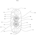
- FIG. 2 illustrates a cross sectional view of the flat drop optical fiber cable 100, in accordance with another embodiment of the present disclosure.
- an optical fiber cable is a network cable that contains strands or array of glass fibers inside an insulated casing.
- the glass fibers are optical transmission elements and, are used to carry optical signals.
- the insulated casing facilitates to protect the optical transmissions elements from heat, cold, harsh environment, unwanted disturbances and external interference from other types of wiring.
- the insulated casing provides protection to the flat drop optical fiber cable 100 from ultraviolet rays of sun.
- the flat drop optical fiber cable 100 is designed for aerial application.
- drop optical fiber cables are specifically designed for fiber-to-the-subscriber applications.
- drop optical fiber cables are dielectric cables ideally suited for self-supporting drop-type installations and in lashed or conduit builds.
- the flat drop optical fiber cable 100 is a flat optical cable.
- flat optical cables are non-circular with two flat or substantially parallel sides.
- the flat drop optical fiber cable 100 is characterized by elliptical cross sectional area with two flat sides.
- the flat drop optical fiber cable 100 is designed to enable higher span length.
- the flat drop optical fiber cable 100 includes easy strippable buffer tubes.
- the flat drop optical fiber cable 100 is designed for long distance transmission of optical signals.
- the flat drop optical fiber cable 100 enables high speed data transmission.
- the flat drop optical fiber cable 100 transmits data at a higher speed than copper data cable.
- the flat drop optical fiber cable 100 transmits data at much higher band width than copper data cable.
- the flat drop optical fiber cable 100 is optimized in weight. In general, light weight optical cables are employed for aerial, duct and underground installations.
- the flat drop optical fiber cable 100 is used for aerial application.
- the flat drop optical fiber cable 100 is used for a wide variety of applications.
- the flat drop optical fiber cable 100 is less susceptible to interference.
- the flat drop optical fiber cable 100 includes one or more buffer tubes 106, a plurality of optical fiber ribbons 108 and one or more water blocking tapes 110.
- the flat drop optical fiber cable 100 includes a cable sheath 112, a plurality of strength members 114 and a plurality of ripcords 116.
- the above combination of structural elements enables an improvement in a plurality of characteristics of the flat drop optical fiber cable 100.
- the plurality of characteristics includes but may not be limited to optical characteristics, mechanical characteristics, electrical characteristics, transmission characteristics and the like.
- the flat drop optical fiber cable 100 includes the one or more buffer tubes 106.
- buffer tubes meet an optimal requirement of dimensions to facilitate free arrangement of the light transmission elements.
- the one or more buffer tubes 106 extends substantially along a longitudinal axis 104.
- the longitudinal axis 104 passes through a geometrical center 102 of the flat drop optical fiber cable 100.
- geometrical center corresponds to a point at center of cross sectional geometry of a body.
- longitudinal axis corresponds to an imaginary axis passing through geometrical center of a body.
- the geometrical center 102 is center of cross sectional geometry of the flat drop optical fiber cable 100.
- the longitudinal axis 104 is an imaginary axis.
- the one or more buffer tubes 106 extend along entire length of the flat drop optical fiber cable 100.
- Each of the one or more buffer tubes 106 is positioned to intersect a first straight line 118.
- the first straight line 118 is an imaginary line.
- the first straight line 118 extends orthogonally to the longitudinal axis 104 of the flat drop optical fiber cable 100.
- the flat drop optical fiber cable 100 includes two buffer tubes.
- the two buffer tubes are positioned substantially along the first straight line 118.
- Each of the one or more buffer tubes 106 provides primary protection to optical fibres of the flat drop optical fiber cable 100.
- the one or more buffer tubes 106 maintain adequate flexibility over a wide range of temperatures.
- the one or more buffer tubes 106 have low moisture sensitivity, good heat resistance, dimensional stability and chemical resistance.
- the one or more buffer tubes 106 forms inner barrier against water penetration and facilitates to isolate the optical fibers from thermal stresses.
- Each of the one or more buffer tubes 106 is a substantially cylindrical tube for encapsulating plurality of optical transmission elements. Each of the one or more buffer tubes 106 is easily strippable. In general, buffer tube of an optical cable is stripped or peeled-off to enable access to optical fibers. The one or more buffer tubes 106 are striped to enable access to the optical fibers of the flat drop optical fiber cable 100. Each of the one or more buffer tubes 106 is finger peelable. Each of the one or more buffer tubes 106 is easily peeled-off with human fingers. Each of the one or more buffer tubes 106 is easily peeled-off with human fingers to enable access to the optical fibers of the flat drop optical fiber cable 100.
- Each of the one or more buffer tubes 106 is circular in cross section. Each of the one or more buffer tubes 106 is uniform in structure and dimensions. Each of the one or more buffer tubes 106 is characterized by a first diameter and a second diameter. The first diameter is an inner diameter of the one or more buffer tubes 106. The second diameter is an outer diameter of the one or more buffer tubes 106. The inner diameter is diameter of internal surface of each of the one or more buffer tubes 106. The inner diameter of each of the one or more buffer tubes 106 is in a range of about 5.30 millimeters ⁇ 0.1 millimeter. In an embodiment the present disclosure, each of the one or more buffer tubes has any suitable value of inner diameter. The outer diameter is diameter of external surface of each of the one or more buffer tubes 106.
- each of the one or more buffer tubes 106 is in a range of about 5.70 millimeters ⁇ 0.1 millimeter. In an embodiment of the present disclosure, each of the one or more buffer tubes has any suitable value of outer diameter. In an embodiment of the present disclosure, the cross section of each of the one or more buffer tubes 106 is of any suitable cross section.12
- each of the one or more buffer tubes 106 is characterized by a first thickness.
- the first thickness is radial thickness of each of the one or more buffer tubes 106 between an inner surface and outer surface of the one or more buffer tubes 106.
- the first thickness of each of the one or more buffer tubes 106 is identical.
- the first thickness of each of the one or more buffer tubes 106 is in a range of about 0.2 millimeters ⁇ 0.05 millimeters.
- each of the one or more buffer tubes 106 has any suitable first thickness.
- Each of the one or more buffer tubes 106 are formed of either low smoke zero halogen or thermoplastic elastomer. In general, low smoke zero halogen and thermoplastic elastomer enable easy stripping or peeling of buffer tube.
- each of the one or more buffer tubes 106 are formed of low smoke zero halogen. In another embodiment of the present disclosure, each of the one or more buffer tubes 106 is formed of thermoplastic elastomer. In yet another embodiment of the present disclosure, each of the one or more buffer tubes 106 is formed of any suitable material which is easily strippable. In yet another embodiment of the present disclosure, each of the one or more buffer tubes 106 is formed of any suitable material of the like.
- the flat drop optical fiber cable 100 includes the plurality of optical fiber ribbons 108.
- the one or more buffer tubes 106 encapsulate the plurality of optical fiber ribbons 108.
- multiple optical fibers are sandwiched, encapsulated, and/or edge bonded to form an optical fiber ribbon.
- optical fiber ribbon cables have inherent advantage of mass fusion splicing. Mass fusion splicing makes installation of optical fiber cable easy and saves time.
- the plurality of optical fiber ribbons 108 enable high packing density and higher counts to enables more efficient use of space.
- the plurality of optical fiber ribbons 108 are prepped and spliced easily.
- the plurality of optical fiber ribbons 108 enable less installation time, less installation labor cost and significantly less emergency restoration time.
- the plurality of optical fiber ribbons 108 are rollable ribbons. In an embodiment of the present disclosure, the plurality of optical fiber ribbons 108 is non-rollable ribbons.
- Each of the plurality of optical fiber ribbons 108 includes a plurality of optical fibers.
- an optical fiber is a light transmission element used for transmitting information as light pulses from one end to another.
- each of the plurality of optical fibers is a thin strand of glass suitable for transmitting optical signals.
- each of the plurality of optical fibers is configured to transmit large amounts of information over long distances with relatively low attenuation.
- the plurality of optical fibers enables optic fiber communication.
- optical fiber communication is a method of transmitting information from one place to another by sending pulses of light through optical fiber. The light forms an electromagnetic carrier wave that is modulated to carry information.
- Each of the plurality of optical fibers is a single mode optical fiber. In an embodiment of the present disclosure, each of the plurality of optical fibers is a multimode optical fiber.
- Each of the plurality of optical fibers in the flat drop optical fiber cable 100 includes a core region and a cladding region.
- the core region is an inner part of an optical fiber and the cladding section is an outer part of the optical fiber.
- the core region is defined by a central longitudinal axis of each of the at least one optical fiber.
- the cladding region surrounds the core region.
- Each of the plurality of optical fibers in the flat drop optical fiber cable 100 is colored optical fiber.
- Each of the plurality of optical fibers is characterized by a diameter.
- the diameter is outer diameter of cladding of each of the plurality of optical fibers.
- the diameter of each of the plurality of optical fibers is about 0.25 millimeters. In an embodiment of the present disclosure, each of the plurality of optical fibers has any suitable diameter of the like.
- the plurality of optical fiber ribbons 108 in the flat drop optical fiber cable 100 is 12.
- the flat drop optical fiber cable 100 includes any suitable number of plurality of optical fiber ribbons 108.
- Each of the plurality of optical fiber ribbons 108 includes 12 optical fibers.
- the flat drop optical fiber cable 100 includes 144 (12> ⁇ 12) optical fibers.
- the flat drop optical fiber cable 100 includes any suitable number of plurality of optical fibers.
- Each of the plurality of optical fiber ribbons 108 is characterized by a ribbon width and a ribbon diameter. In general, ribbon width corresponds to maximum end-to-end distance between two extremes optical fibers in a ribbon.
- the ribbon height corresponds to dimension of side orthogonal to the ribbon width.
- the ribbon width of each of the plurality of optical fiber ribbons 108 is about 3.2 millimeters.
- the ribbon height of each of the plurality of optical fiber ribbons 108 is about 0.32 millimeters.
- the optical fiber ribbons 108 have any suitable value of ribbon width and ribbon height.
- the flat drop optical fiber cable 100 includes the one or more water blocking tapes 110.
- water blocking tape is formed of water resistant material and prevents ingression of water and moisture.
- the one or more water blocking tapes 110 are characterized by substantially cylindrical shape.
- the one or more water blocking tapes 110 are positioned the flat drop optical fiber cable 100 in one or more arrangements.
- the one or more arrangements include a first arrangement and a second arrangement.
- the first arrangement includes a buffer tube of the one or more buffer tubes 106 encapsulated by a water blocking tape of the one or more water blocking tapes 110.
- the water blocking tape of the one or more water blocking tapes 110 circumferentially surrounds the buffer tube of the one or more buffer tubes 106.
- the water blocking tape surrounds the buffer tube along entire length of the flat drop optical fiber cable 100 (as shown in FIG. 2 ).
- each of the one or more water blocking tapes 110 encapsulates each of the one or more buffer tubes 106.
- the second arrangement includes a water blocking tape of the one or more water blocking tapes 110 encapsulated by a buffer tube of the one or more buffer tubes 106.
- the buffer tube of the one or more buffer tubes 106 circumferentially surrounds the water blocking tape of the one or more water blocking tapes 110.
- the buffer tube surrounds the water blocking tape along entire length of the flat drop optical fiber cable 100.
- the one or more water blocking tapes 110 are positioned in the flat drop optical fiber cable 100 in any suitable manner.
- the flat drop optical fiber cable 100 includes a plurality of one or more arrangements.
- the one or more water blocking tapes 110 is characterized by a second thickness.
- the second thickness corresponds to thickness of the one or more water blocking tapes 110 inside the one or more buffer tubes 106.
- the second thickness of the one or more water blocking tapes 110 is about 0.3 millimeter.
- the one or more water blocking tapes 110 is characterized by a first width and a second width.
- the first width is width of the one or more water blocking tapes 110 positioned inside the one or more buffer tubes 106.
- the first width of the one or more water blocking tapes 110 is in a range of about 23 millimeters ⁇ 1 millimeter.
- the second width is width of the one or more water blocking tapes 110 positioned around the one or more buffer tubes 106.
- the second width of the one or more water blocking tapes 110 is in a range of about 22 millimeters ⁇ 1 millimeter.
- the flat drop optical fiber cable 100 includes the cable sheath 112.
- the cable sheath 112 encapsulates the one or more buffer tubes 106 and the one or more water blocking tapes 110.
- cable sheath is outermost layer of an optical cable and protects the optical cable from external hazards.
- the cable sheath 112 protects the flat drop optical fiber cable 100 from moisture, dust, dirt, harmful environment and UV rays.
- the cable sheath 112 extends substantially along entire length of the flat drop optical fiber cable 100.
- the cable sheath 112 is a covering jacket of the flat drop optical fiber cable 100.
- the cable sheath 112 protects core of optical fiber cables 100 from harsh environment, water, moisture, dust, external radiations, mechanical forces and harmful UV rays.
- the cable sheath 112 is black in color. In an embodiment of the present disclosure, the cable sheath 112 is of any suitable color of the like.
- the cable sheath 112 is characterized by a substantially elliptical cross sectional area.
- the substantially elliptical cross sectional area of the cable sheath 112 is associated with a major axis and a minor axis.
- major axis corresponds to a line segment passing through center and connecting the widest points on perimeter of ellipse.
- minor axis corresponds to a line segment passing through center and connecting the nearest points on perimeter of ellipse.
- the major axis of the substantially elliptical cross section is parallel to the first straight line 118.
- the substantially elliptical cross sectional area of the cable sheath 112 includes a first flat side 120 and a second flat side 122.
- the substantially elliptical cross sectional area of the cable sheath 112 includes a first arc 124 and a second arc 126.
- the first arc 124 extends from one end of the first flat side 120 to corresponding one end of the second flat side 122.
- the second arc joins 126 extends from other end of the first flat side 120 to corresponding other end of the second flat side 122.
- the first flat side 120 is parallel to the second flat side 122.
- the first flat side 120 and the second flat side 122 of the cable sheath 112 are parallel to the first straight line 118.
- the first flat side 120 and the second flat side 122 of the cable sheath 112 are parallel to the major axis of the cable sheath 112.
- the first flat side 120 and the second flat side 122 extend substantially along entire length of the flat drop optical fiber cable 100.
- the cable sheath 112 is characterized by a third thickness.
- the third thickness corresponds to minimum thickness of the cable sheath 112 over the one or more buffer tubes 106.
- the third thickness Is shortest distance between the one or more buffer tubes 106 and the cable sheath 112.
- the third thickness of the cable sheath 112 is in a range of about 1.4 millimeters ⁇ 0.1 millimeter.
- the cable sheath 112 is formed of either polyethylene or low smoke zero halogen.
- polyethylene is usually a mixture of similar polymers of ethylene with various number of polyethylene molecules. Polyethylene is a rugged flexible and durable material.
- low smoke zero halogen emits limited smoke, no halogen and won't produce dangerous gas when exposed to high sources of heat.
- the cable sheath 112 is formed of any suitable material of the like.
- the flat drop optical fiber cable 100 includes a plurality of strength members 114.
- the plurality of strength members 114 are embedded in the cable sheath 112.
- strength members provide tensile strength and mechanical support to optical fiber cable.
- the plurality of strength members 114 is positioned to intersect the first straight line 118.
- the first straight line 118 includes a first end and a second end. The first end and the second end are two extreme ends of the first straight line 118.
- the plurality of strength members 114 are positioned at the first end and the second end of the first straight line 118.
- the flat drop optical fiber cable 100 includes two strength members.
- the two strength members are positioned at the first end and at the second end of the flat drop optical fiber cable 100.
- the plurality of strength members 114 is positioned at any suitable position of the like.
- Each of the plurality of strength members 114 is circular in cross section.
- the center of the circular cross section of the plurality of strength members 114 lies substantially along the first straight line 118.
- the plurality of strength members 114 is of any other suitable cross section.
- the plurality of strength members 114 is characterized by a third diameter.
- the third diameter is diameter of circular cross section of each of the plurality of strength members 114.
- the third diameter of each of the plurality of strength members 114 is in a range of about 2.2 millimeters ⁇ 0.05 millimeters.
- each of the plurality of strength members 114 has any suitable value of the first diameter.
- the plurality of strength members 114 lies substantially along the longitudinal axis 104 of the flat drop optical fiber cable 100.
- the plurality of strength members 114 extends along entire length of the flat drop optical fiber cable 100.
- the plurality of strength members 114 bears forces applied on the flat drop optical fiber cable 100 during maintenance, installation and regular use.
- the plurality strength members 114 prevents the flat drop optical fiber cable 100 from damage and increases life span of the flat drop optical fiber cable 100.
- the plurality of strength members 114 provides physical strength to the flat drop optical fiber cable 100 and resists over bending of the flat drop optical fiber cable 100.
- the plurality of strength members 114 provides tensile strength to the flat drop optical fiber cable 100.
- the plurality of strength members 114 provides structural resistance the flat drop optical fiber cable 100 against buckling.
- Each of the plurality of strength members 114 is formed of either fiber reinforced plastic or aramid reinforced plastic. In an embodiment of the present disclosure, the plurality of strength members 114 is formed of any suitable material.
- the cable sheath 112 is characterized by a fourth thickness and a fifth thickness.
- the fourth thickness is thickness of the cable sheath 112 between the one or more buffer tubes 106 and a nearest strength member of the plurality of strength members 114.
- the fourth thickness of the cable sheath 112 is in a range of about 0.4 millimeter ⁇ 0.1 millimeter.
- the fifth thickness is thickness of the cable sheath 112 over the plurality of strength members 114 in direction perpendicular to the first straight line 118.
- the fifth thickness of the cable sheath 112 is in a range of about 0.8 millimeter ⁇ 0.1 millimeter.
- the cable sheath 112 has any suitable value of thickness.
- the flat drop optical fiber cable 100 includes the plurality of ripcords 116.
- the plurality of ripcords 116 is embedded in the cable sheath 112.
- the plurality of ripcords 116 extends substantially along entire length of the flat drop optical fiber cable 100.
- ripcords facilitate in striping of outer sheath of optical cables to enable access to optical fibers.
- the plurality of ripcords 116 facilitates striping of the cable sheath 112 of the flat drop optical fiber cable 100.
- the plurality of ripcords 116 facilitates striping of the cable sheath 112 to enable access to the plurality of optical fiber ribbons 108.
- the plurality of ripcords 116 is positioned around the one or more buffer tubes 106. In an embodiment of the present disclosure, the plurality of ripcords 116 is positioned at any suitable position of the like.
- the plurality of ripcords 116 is formed of either polyester or aramids. In another embodiment of the present disclosure, the plurality of ripcords 116 is formed of any other suitable material. In an embodiment of the present disclosure, number of plurality of ripcords 116 in the flat drop optical fiber cable 100 is 2. In another embodiment of the present disclosure, number of plurality of ripcords 116 may vary. In an embodiment of the present disclosure, the plurality of ripcords 116 is of yellow color. In another embodiment of the present disclosure, the plurality of ripcords 116 is of any suitable color of the like.
- the flat drop optical fiber cable 100 is characterized by a cable width.
- the cable width of the flat drop optical fiber cable 100 corresponds to shortest distance between the first flat side 120 and the second flat side 122.
- the cable width of the flat drop optical fiber cable 100 is measured along a straight line orthogonal to the first flat side 120 or the second flat side 122.
- the cable width of the fiat drop optical fiber cable 100 is about 8.8 millimeters.
- the flat drop optical fiber cable 100 has any suitable value of the cable width.
- the flat drop optical fiber cable 100 is characterized by a cable height.
- the cable height of the flat drop optical fiber cable 100 corresponds to maximum distance between the first arc 124 and the second arc 126.
- the cable height of the flat drop optical fiber cable 100 is measured along a straight line parallel to the first fiat side 120. In an embodiment of the present disclosure, the cable height of the flat drop optical fiber cable 100 is about 13.1 millimeters. In another embodiment of the present disclosure, the flat drop optical fiber cable 100 has any suitable value of cable height.
- the flat drop optical fiber cable 100 is characterized by a cable weight. The cable weight corresponds to weight of the flat drop optical fiber cable 100. In an embodiment of the present disclosure, the cable weight of the flat drop optical fiber cable 100 is about 110 kilograms per kilometer. In an embodiment of the present disclosure, the flat drop optical fiber cable 100 has any suitable value of the cable weight.
- the flat drop optical fiber cable 100 is UV resistant.
- the cable sheath 112 of the flat drop optical fiber cable 100 is formed of UV resistant material.
- the flat drop optical fiber cable 100 is resistant to harmful UV rays of sun.
- the flat drop optical fiber cable 100 is ideal for aerial application.
- the flat drop optical fiber cable 100 includes the plurality of strength members 114 embedded in the cable sheath 112.
- the plurality of strength members 114 of the flat drop optical fiber cable 100 enable anti-buckling properties.
- the flat drop optical fiber cable 100 is resistant to buckling.
- the one or more buffer tubes 106 of the flat drop optical fiber cable 100 are easily strippable.
- the flat drop optical fiber cable 100 enable easy access to the plurality of optical fiber ribbons 108.
- the flat drop optical fiber cable 100 is light in weight.
- the flat drop optical fiber cable 100 is characterized by easy fiber access.
- the flat drop optical fiber cable 100 enable easy access to the plurality of optical fibers due to finger peelable buffer tubes.
- the flat drop optical fiber cable 100 enable easy access to the plurality of optical fibers due to the cable sheath 112.
- the flat drop optical fiber cable 100 is low in cost.
- the flat drop optical fiber cable 100 is less prone to wind pressure loads.
- the flat drop optical fiber cable 100 is gel free and dry optical cable.
- the flat drop optical fiber cable 100 is characterized by a reduced installation time.
- the reduced installation time of the flat drop optical fiber cable 100 is due to gel free and dry construction.
- the reduced installation time of the flat drop optical fiber cable 100 is due to the plurality of optical fiber ribbons 108.
- the plurality of optical fiber ribbons 108 allow mass fusion splicing to enable the reduced installation time.
- the flat drop optical fiber cable enable higher span length for aerial application.
- the flat drop optical fiber cable has numerous advantages over the prior art.
- the flat drop optical fiber cable is ideal for aerial application.
- the flat drop optical fiber cable has optimized design and dimensions.
- the flat drop optical fiber cable has a reduced weight.
- the reduced weight of the cable enables the easier aerial application of the flat drop optical fiber cable.
- the flat drop optical fiber cable is a cable with a single layer construction.
- the single layer construction enables a decrease in manufacturing time for the flat drop optical fiber cable.
- the single layer construction allows easier access to optical fibers of the flat drop optical fiber cable during mid-spanning.
Landscapes
- Physics & Mathematics (AREA)
- General Physics & Mathematics (AREA)
- Optics & Photonics (AREA)
- Light Guides In General And Applications Therefor (AREA)
Claims (10)
- Câble à fibre optique de dérivation plat (100), comprenant :un ou plusieurs tubes tampons (106), dans lequel l'un ou plusieurs tubes tampons (106) s'étendent sensiblement le long d'un axe longitudinal (104) passant par un centre géométrique (102) du câble à fibre optique de dérivation plat (100), dans lequel chacun de l'un ou plusieurs tubes tampons (106) est positionné pour croiser une première ligne droite (118) s'étendant orthogonalement à l'axe longitudinal (104) du câble à fibre optique de dérivation plat (100), dans lequel l'un ou plusieurs tubes tampons (106) s'étendent sur toute la longueur du câble à fibre optique de dérivation plat (100), et dans lequel l'un ou plusieurs tubes tampons (106) sont formés sans halogènes à faible dégagement de fumées ou d'un élastomère thermoplastique ;une pluralité de bandes de fibres optiques (108), dans lequel chacune de la pluralité de bandes de fibres optiques (108) comprend une pluralité de fibres optiques, dans lequel l'un ou plusieurs tubes tampons (106) encapsulent la pluralité de bandes de fibres optiques (108), dans lequel la pluralité de fibres optiques dans le câble à fibre optique de dérivation plat (100) est de 144, dans lequel le câble à fibre optique de dérivation plat (100) a un poids de 110 kilogrammes par kilomètre ; etune gaine de câble (112) encapsulant l'un ou plusieurs tubes tampons (106) et la pluralité de bandes de fibres optiques (108), dans lequel la gaine de câble (112) a une section transversale sensiblement elliptique de façon à ce que la section transversale sensiblement elliptique de la gaine de câble (112) comprenne un premier côté plat (120) et un second côté plat (122) parallèle à la première ligne droite (118), et dans lequel chacun de l'un ou plusieurs tubes tampons (106) a une section transversale circulaire, encapsulée dans la section transversale elliptique de la gaine de câble (112), dans lequel chacun de l'un ou plusieurs tubes tampons (106) est démembrable ou pelable par un doigt, et dans lequel une épaisseur minimale de la gaine de câble (112) sur l'un ou plusieurs tubes tampons (106) est dans une plage d'environ 1,4 millimètre± 0,1 millimètre.
- Câble à fibre optique de dérivation plat (100) selon la revendication 1, dans lequel la pluralité de bandes de fibres optiques (108) sont des bandes enroulables ou des bandes non enroulables.
- Câble de fibre optique de dérivation plat (100) selon la revendication 1, dans lequel le poids réduit du câble à fibre optique de dérivation plat (100) permet une augmentation de la longueur de portée, et dans lequel la gaine de câble (112) est formée de polyéthylènes ou sans halogènes à faible dégagement de fumées.
- Câble à fibre optique de dérivation plat (100) selon l'une quelconque des revendications précédentes, dans lequel une ou plusieurs bandes de blocage d'eau (110) sont positionnées dans le câble à fibre optique de dérivation plat (100) selon un premier agencement ou un second agencement,dans lequel le premier agencement comprend un tube tampon de l'un ou plusieurs tubes tampons (106) encapsulé par une bande de blocage d'eau de l'une ou plusieurs bandes de blocage d'eau (110), dans lequel la bande de blocage d'eau entoure circonférentiellement le tube tampon de l'un ou plusieurs tubes tampons (106) le long de la longueur du câble à fibre optique de dérivation plat (100), etdans lequel le second agencement comprend une bande de blocage d'eau de l'une ou plusieurs bandes de blocage d'eau (110) encapsulée par un tube tampon de l'un ou plusieurs tubes tampons (106), et dans lequel le tube tampon de l'un ou plusieurs tubes tampons (106) entoure circonférentiellement la bande de blocage d'eau de l'une ou plusieurs bandes de blocage d'eau (110) le long d'une longueur du câble à fibre optique de dérivation plat (100).
- Câble à fibre optique de dérivation plat (100) selon l'une quelconque des revendications précédentes, comprenant en outre une pluralité d'éléments de résistance (114), dans lequel la pluralité d'éléments de résistance (114) est insérée dans la gaine de câble (112), et dans lequel au moins un d'un diamètre de chacun de la pluralité d'éléments de résistance (114) est dans une plage de 2,2 millimètres à± 0,05 millimètres, et dans lequel une épaisseur de la gaine de câble (112) entre l'un ou plusieurs tubes tampons (106) et un élément de résistance le plus proche de la pluralité d'éléments de résistance (114) est dans une plage de 0,4 à millimètres à± 0,1 millimètres et l'épaisseur de la gaine de câble (112) sur la pluralité d'éléments de résistance (114) dans une direction perpendiculaire à la première ligne droite (118) est dans une plage de 0,8 millimètres à ± 0,1 millimètres.
- Câble à fibre optique de dérivation plat (100) selon l'une quelconque des revendications précédentes, dans lequel le câble à fibre optique de dérivation plat (100) a une largeur de câble d'environ 8,8 millimètres et une hauteur de câble d'environ 13,1 millimètres.
- Câble à fibre optique de dérivation plat (100) selon l'une quelconque des revendications précédentes, dans lequel chacune de la pluralité de bandes de fibres optiques (108) est caractérisée par une largeur de bande et une hauteur de bande, dans lequel la largeur de bande est d'environ 3,2 millimètres, dans lequel la hauteur de bande est d'environ 0,32 millimètres.
- Câble à fibre optique de dérivation plat (100) selon l'une quelconque des revendications précédentes, dans lequel chacun de l'un ou plusieurs tubes tampons (106) est caractérisé par une première épaisseur, un premier diamètre et un second diamètre, dans lequel la première épaisseur de chacun de l'un ou plusieurs tubes tampons (106) est dans une plage d'environ 0,2 millimètre± 0,05 millimètre, dans lequel le premier diamètre de chacun de l'un ou plusieurs tubes tampons (106) est dans une plage d'environ 5,30 millimètres± 0,1 millimètre, dans lequel le second diamètre de chacun de l'un ou plusieurs tubes tampons (106) est dans une plage d'environ 5,70 millimètres± 0,1 millimètre,
dans lequel la première épaisseur est une épaisseur radiale de chacun de l'un ou plusieurs tubes tampons (106) entre le premier diamètre et le second diamètre de l'un ou plusieurs tubes tampons (106), dans lequel la première épaisseur de chacun de l'un ou plusieurs tubes tampons (106) est identique. - Câble à fibre optique de dérivation plat (100) selon l'une quelconque des revendications précédentes, comprenant en outre une pluralité de filins de déchirement (116), dans lequel la pluralité de filins de déchirement (116) est insérée dans la gaine de câble (112).
- Câble à fibre optique de dérivation plat (100) selon la revendication 4, dans lequel la pluralité de bandes de fibres optiques (108) dans le câble à fibre optique de dérivation plat (100) est de 12, dans lequel chacune de la pluralité de bandes de fibres optiques (108) comprend 12 fibres optiques.
Applications Claiming Priority (1)
| Application Number | Priority Date | Filing Date | Title |
|---|---|---|---|
| IN201821046209 | 2018-12-06 |
Publications (2)
| Publication Number | Publication Date |
|---|---|
| EP3663825A1 EP3663825A1 (fr) | 2020-06-10 |
| EP3663825B1 true EP3663825B1 (fr) | 2025-02-12 |
Family
ID=65276090
Family Applications (1)
| Application Number | Title | Priority Date | Filing Date |
|---|---|---|---|
| EP19154928.6A Active EP3663825B1 (fr) | 2018-12-06 | 2019-01-31 | Câble de descente à fibre optique plat |
Country Status (2)
| Country | Link |
|---|---|
| US (1) | US11125959B2 (fr) |
| EP (1) | EP3663825B1 (fr) |
Families Citing this family (2)
| Publication number | Priority date | Publication date | Assignee | Title |
|---|---|---|---|---|
| CN113805292B (zh) * | 2020-06-12 | 2023-03-03 | 华为技术有限公司 | 一种蝶形光缆和光通信系统 |
| EP4248251A4 (fr) * | 2020-11-19 | 2024-10-23 | Corning Research & Development Corporation | Câble à haute densité et à faible diamètre pourvu d'un ruban de fibres optiques enroulable |
Citations (1)
| Publication number | Priority date | Publication date | Assignee | Title |
|---|---|---|---|---|
| US20070025668A1 (en) * | 2005-07-29 | 2007-02-01 | Greenwood Jody L | Fiber optic cables and assemblies for fiber to the subscriber applications |
Family Cites Families (16)
| Publication number | Priority date | Publication date | Assignee | Title |
|---|---|---|---|---|
| JPS58150907A (ja) * | 1982-03-03 | 1983-09-07 | Nippon Telegr & Teleph Corp <Ntt> | 心線テ−プ内蔵光フアイバケ−ブル |
| US4844575A (en) * | 1987-04-10 | 1989-07-04 | American Telephone And Telegraph Company, At&T Bell Laboratories | Optical fiber cable |
| US6101305A (en) * | 1997-12-15 | 2000-08-08 | Siecor Corporation | Fiber optic cable |
| US6215931B1 (en) * | 1999-01-26 | 2001-04-10 | Alcatel | Flexible thermoplastic polyolefin elastomers for buffering transmission elements in a telecommunications cable |
| US6870995B2 (en) * | 2001-07-05 | 2005-03-22 | Pirelli Cables And Systems Llc | High fiber count optical fiber cable with buffer tubes around central strength member |
| US7277615B2 (en) * | 2002-12-19 | 2007-10-02 | Corning Cable Systems, Llc. | Fiber optic cable having a dry insert and methods of making the same |
| US7391944B2 (en) * | 2005-08-25 | 2008-06-24 | Draka Comteq B.V. | Fiber optic cable with a concave surface |
| US20080013898A1 (en) * | 2006-07-11 | 2008-01-17 | Wells Dennis R | Multi-piece protective mold |
| US7406232B2 (en) * | 2006-08-31 | 2008-07-29 | Corning Cable Systems Llc | Non-round fiber optic cable having improved major axis crush resistance |
| AU2009322446A1 (en) * | 2008-12-02 | 2011-06-30 | Corning Cable Systems Llc | Optical fiber array cables and associated fiber optic cables and systems |
| US20130022325A1 (en) * | 2011-07-21 | 2013-01-24 | Adc Telecommunications, Inc. | Drop Cable with Fiber Ribbon Conforming to Fiber Passage |
| JP5564026B2 (ja) * | 2011-10-18 | 2014-07-30 | 株式会社フジクラ | 光ファイバテープ心線及びその光ファイバテープ心線を収納した光ファイバケーブル |
| EP3432047A1 (fr) * | 2012-05-02 | 2019-01-23 | Fujikura Ltd. | Câbles optiques ronds et de petit diamètre avec une structure de fibre optique en forme de ruban |
| PL3876012T3 (pl) * | 2016-05-25 | 2026-02-23 | Corning Optical Communications LLC | Kabel światłowodowy o wysokiej gęstości włókien i niskich stratach na zgięciu |
| US20190113703A1 (en) * | 2017-10-12 | 2019-04-18 | Superior Essex International LP | Fiber Optic Drop Cable |
| WO2019108384A1 (fr) * | 2017-11-30 | 2019-06-06 | Corning Research & Development Corporation | Câble à fibre optique pour détection distribuée avec des composants résistant aux rongeurs en matériaux durcis |
-
2019
- 2019-01-29 US US16/261,270 patent/US11125959B2/en active Active
- 2019-01-31 EP EP19154928.6A patent/EP3663825B1/fr active Active
Patent Citations (1)
| Publication number | Priority date | Publication date | Assignee | Title |
|---|---|---|---|---|
| US20070025668A1 (en) * | 2005-07-29 | 2007-02-01 | Greenwood Jody L | Fiber optic cables and assemblies for fiber to the subscriber applications |
Also Published As
| Publication number | Publication date |
|---|---|
| US11125959B2 (en) | 2021-09-21 |
| US20200183118A1 (en) | 2020-06-11 |
| EP3663825A1 (fr) | 2020-06-10 |
Similar Documents
| Publication | Publication Date | Title |
|---|---|---|
| US20220357539A1 (en) | Round and small diameter optical cables with a ribbon-like optical fiber structure | |
| EP3447558B1 (fr) | Câble de conduit de ruban de fibres optiques | |
| US6785450B2 (en) | Self-supporting fiber optic cable | |
| US4272155A (en) | Optical cables | |
| US11187866B2 (en) | Fiber multitube optical fiber cable | |
| US10921541B2 (en) | Cylindrical enclosure for optical waveguide cable | |
| EP2513695B1 (fr) | Câble à sous-ensembles multifibres | |
| US11156792B2 (en) | Loose tube cable with embedded strength member | |
| EP3514593B1 (fr) | Câble à fibre optique à ruban de tube central flexible | |
| EP3663825B1 (fr) | Câble de descente à fibre optique plat | |
| EP3451036A1 (fr) | Câble de guide d'onde optique pour largage aérien | |
| KR20110012705A (ko) | 센터럴 루즈튜브 이중피복 광섬유 케이블 | |
| US11300742B2 (en) | Optical fiber ribbon cable | |
| EP3226047B1 (fr) | Câble à fibres optiques à couche unique pour application de micro-conduit | |
| TWM677435U (zh) | 光纖纜線 | |
| KR20130117959A (ko) | 광섬유 케이블 |
Legal Events
| Date | Code | Title | Description |
|---|---|---|---|
| PUAI | Public reference made under article 153(3) epc to a published international application that has entered the european phase |
Free format text: ORIGINAL CODE: 0009012 |
|
| STAA | Information on the status of an ep patent application or granted ep patent |
Free format text: STATUS: THE APPLICATION HAS BEEN PUBLISHED |
|
| AK | Designated contracting states |
Kind code of ref document: A1 Designated state(s): AL AT BE BG CH CY CZ DE DK EE ES FI FR GB GR HR HU IE IS IT LI LT LU LV MC MK MT NL NO PL PT RO RS SE SI SK SM TR |
|
| AX | Request for extension of the european patent |
Extension state: BA ME |
|
| STAA | Information on the status of an ep patent application or granted ep patent |
Free format text: STATUS: REQUEST FOR EXAMINATION WAS MADE |
|
| 17P | Request for examination filed |
Effective date: 20201210 |
|
| RBV | Designated contracting states (corrected) |
Designated state(s): AL AT BE BG CH CY CZ DE DK EE ES FI FR GB GR HR HU IE IS IT LI LT LU LV MC MK MT NL NO PL PT RO RS SE SI SK SM TR |
|
| STAA | Information on the status of an ep patent application or granted ep patent |
Free format text: STATUS: EXAMINATION IS IN PROGRESS |
|
| 17Q | First examination report despatched |
Effective date: 20210818 |
|
| GRAP | Despatch of communication of intention to grant a patent |
Free format text: ORIGINAL CODE: EPIDOSNIGR1 |
|
| STAA | Information on the status of an ep patent application or granted ep patent |
Free format text: STATUS: GRANT OF PATENT IS INTENDED |
|
| INTG | Intention to grant announced |
Effective date: 20240502 |
|
| GRAJ | Information related to disapproval of communication of intention to grant by the applicant or resumption of examination proceedings by the epo deleted |
Free format text: ORIGINAL CODE: EPIDOSDIGR1 |
|
| STAA | Information on the status of an ep patent application or granted ep patent |
Free format text: STATUS: EXAMINATION IS IN PROGRESS |
|
| INTC | Intention to grant announced (deleted) | ||
| GRAS | Grant fee paid |
Free format text: ORIGINAL CODE: EPIDOSNIGR3 |
|
| STAA | Information on the status of an ep patent application or granted ep patent |
Free format text: STATUS: GRANT OF PATENT IS INTENDED |
|
| GRAP | Despatch of communication of intention to grant a patent |
Free format text: ORIGINAL CODE: EPIDOSNIGR1 |
|
| INTG | Intention to grant announced |
Effective date: 20240906 |
|
| GRAA | (expected) grant |
Free format text: ORIGINAL CODE: 0009210 |
|
| STAA | Information on the status of an ep patent application or granted ep patent |
Free format text: STATUS: THE PATENT HAS BEEN GRANTED |
|
| AK | Designated contracting states |
Kind code of ref document: B1 Designated state(s): AL AT BE BG CH CY CZ DE DK EE ES FI FR GB GR HR HU IE IS IT LI LT LU LV MC MK MT NL NO PL PT RO RS SE SI SK SM TR |
|
| REG | Reference to a national code |
Ref country code: GB Ref legal event code: FG4D |
|
| REG | Reference to a national code |
Ref country code: CH Ref legal event code: EP |
|
| REG | Reference to a national code |
Ref country code: DE Ref legal event code: R096 Ref document number: 602019065673 Country of ref document: DE |
|
| REG | Reference to a national code |
Ref country code: IE Ref legal event code: FG4D |
|
| REG | Reference to a national code |
Ref country code: NL Ref legal event code: MP Effective date: 20250212 |
|
| PG25 | Lapsed in a contracting state [announced via postgrant information from national office to epo] |
Ref country code: RS Free format text: LAPSE BECAUSE OF FAILURE TO SUBMIT A TRANSLATION OF THE DESCRIPTION OR TO PAY THE FEE WITHIN THE PRESCRIBED TIME-LIMIT Effective date: 20250512 |
|
| PG25 | Lapsed in a contracting state [announced via postgrant information from national office to epo] |
Ref country code: FI Free format text: LAPSE BECAUSE OF FAILURE TO SUBMIT A TRANSLATION OF THE DESCRIPTION OR TO PAY THE FEE WITHIN THE PRESCRIBED TIME-LIMIT Effective date: 20250212 |
|
| PG25 | Lapsed in a contracting state [announced via postgrant information from national office to epo] |
Ref country code: PL Free format text: LAPSE BECAUSE OF FAILURE TO SUBMIT A TRANSLATION OF THE DESCRIPTION OR TO PAY THE FEE WITHIN THE PRESCRIBED TIME-LIMIT Effective date: 20250212 |
|
| PG25 | Lapsed in a contracting state [announced via postgrant information from national office to epo] |
Ref country code: ES Free format text: LAPSE BECAUSE OF FAILURE TO SUBMIT A TRANSLATION OF THE DESCRIPTION OR TO PAY THE FEE WITHIN THE PRESCRIBED TIME-LIMIT Effective date: 20250212 |
|
| REG | Reference to a national code |
Ref country code: LT Ref legal event code: MG9D |
|
| PG25 | Lapsed in a contracting state [announced via postgrant information from national office to epo] |
Ref country code: NO Free format text: LAPSE BECAUSE OF FAILURE TO SUBMIT A TRANSLATION OF THE DESCRIPTION OR TO PAY THE FEE WITHIN THE PRESCRIBED TIME-LIMIT Effective date: 20250512 Ref country code: IS Free format text: LAPSE BECAUSE OF FAILURE TO SUBMIT A TRANSLATION OF THE DESCRIPTION OR TO PAY THE FEE WITHIN THE PRESCRIBED TIME-LIMIT Effective date: 20250612 |
|
| PG25 | Lapsed in a contracting state [announced via postgrant information from national office to epo] |
Ref country code: NL Free format text: LAPSE BECAUSE OF FAILURE TO SUBMIT A TRANSLATION OF THE DESCRIPTION OR TO PAY THE FEE WITHIN THE PRESCRIBED TIME-LIMIT Effective date: 20250212 |
|
| PG25 | Lapsed in a contracting state [announced via postgrant information from national office to epo] |
Ref country code: HR Free format text: LAPSE BECAUSE OF FAILURE TO SUBMIT A TRANSLATION OF THE DESCRIPTION OR TO PAY THE FEE WITHIN THE PRESCRIBED TIME-LIMIT Effective date: 20250212 |
|
| PG25 | Lapsed in a contracting state [announced via postgrant information from national office to epo] |
Ref country code: PT Free format text: LAPSE BECAUSE OF FAILURE TO SUBMIT A TRANSLATION OF THE DESCRIPTION OR TO PAY THE FEE WITHIN THE PRESCRIBED TIME-LIMIT Effective date: 20250612 Ref country code: LV Free format text: LAPSE BECAUSE OF FAILURE TO SUBMIT A TRANSLATION OF THE DESCRIPTION OR TO PAY THE FEE WITHIN THE PRESCRIBED TIME-LIMIT Effective date: 20250212 |
|
| PG25 | Lapsed in a contracting state [announced via postgrant information from national office to epo] |
Ref country code: GR Free format text: LAPSE BECAUSE OF FAILURE TO SUBMIT A TRANSLATION OF THE DESCRIPTION OR TO PAY THE FEE WITHIN THE PRESCRIBED TIME-LIMIT Effective date: 20250513 Ref country code: BG Free format text: LAPSE BECAUSE OF FAILURE TO SUBMIT A TRANSLATION OF THE DESCRIPTION OR TO PAY THE FEE WITHIN THE PRESCRIBED TIME-LIMIT Effective date: 20250212 |
|
| REG | Reference to a national code |
Ref country code: AT Ref legal event code: MK05 Ref document number: 1766569 Country of ref document: AT Kind code of ref document: T Effective date: 20250212 |
|
| PG25 | Lapsed in a contracting state [announced via postgrant information from national office to epo] |
Ref country code: SE Free format text: LAPSE BECAUSE OF FAILURE TO SUBMIT A TRANSLATION OF THE DESCRIPTION OR TO PAY THE FEE WITHIN THE PRESCRIBED TIME-LIMIT Effective date: 20250212 |
|
| PG25 | Lapsed in a contracting state [announced via postgrant information from national office to epo] |
Ref country code: SM Free format text: LAPSE BECAUSE OF FAILURE TO SUBMIT A TRANSLATION OF THE DESCRIPTION OR TO PAY THE FEE WITHIN THE PRESCRIBED TIME-LIMIT Effective date: 20250212 |
|
| PG25 | Lapsed in a contracting state [announced via postgrant information from national office to epo] |
Ref country code: DK Free format text: LAPSE BECAUSE OF FAILURE TO SUBMIT A TRANSLATION OF THE DESCRIPTION OR TO PAY THE FEE WITHIN THE PRESCRIBED TIME-LIMIT Effective date: 20250212 |
|
| PG25 | Lapsed in a contracting state [announced via postgrant information from national office to epo] |
Ref country code: IT Free format text: LAPSE BECAUSE OF FAILURE TO SUBMIT A TRANSLATION OF THE DESCRIPTION OR TO PAY THE FEE WITHIN THE PRESCRIBED TIME-LIMIT Effective date: 20250212 |
|
| PG25 | Lapsed in a contracting state [announced via postgrant information from national office to epo] |
Ref country code: AT Free format text: LAPSE BECAUSE OF FAILURE TO SUBMIT A TRANSLATION OF THE DESCRIPTION OR TO PAY THE FEE WITHIN THE PRESCRIBED TIME-LIMIT Effective date: 20250212 |
|
| PG25 | Lapsed in a contracting state [announced via postgrant information from national office to epo] |
Ref country code: CZ Free format text: LAPSE BECAUSE OF FAILURE TO SUBMIT A TRANSLATION OF THE DESCRIPTION OR TO PAY THE FEE WITHIN THE PRESCRIBED TIME-LIMIT Effective date: 20250212 Ref country code: EE Free format text: LAPSE BECAUSE OF FAILURE TO SUBMIT A TRANSLATION OF THE DESCRIPTION OR TO PAY THE FEE WITHIN THE PRESCRIBED TIME-LIMIT Effective date: 20250212 |
|
| PG25 | Lapsed in a contracting state [announced via postgrant information from national office to epo] |
Ref country code: RO Free format text: LAPSE BECAUSE OF FAILURE TO SUBMIT A TRANSLATION OF THE DESCRIPTION OR TO PAY THE FEE WITHIN THE PRESCRIBED TIME-LIMIT Effective date: 20250212 |
|
| PG25 | Lapsed in a contracting state [announced via postgrant information from national office to epo] |
Ref country code: SK Free format text: LAPSE BECAUSE OF FAILURE TO SUBMIT A TRANSLATION OF THE DESCRIPTION OR TO PAY THE FEE WITHIN THE PRESCRIBED TIME-LIMIT Effective date: 20250212 |
|
| REG | Reference to a national code |
Ref country code: DE Ref legal event code: R097 Ref document number: 602019065673 Country of ref document: DE |
|
| PLBE | No opposition filed within time limit |
Free format text: ORIGINAL CODE: 0009261 |
|
| STAA | Information on the status of an ep patent application or granted ep patent |
Free format text: STATUS: NO OPPOSITION FILED WITHIN TIME LIMIT |
|
| 26N | No opposition filed |
Effective date: 20251113 |