EP3663776A1 - Leitungspfostensensor - Google Patents
Leitungspfostensensor Download PDFInfo
- Publication number
- EP3663776A1 EP3663776A1 EP19214145.5A EP19214145A EP3663776A1 EP 3663776 A1 EP3663776 A1 EP 3663776A1 EP 19214145 A EP19214145 A EP 19214145A EP 3663776 A1 EP3663776 A1 EP 3663776A1
- Authority
- EP
- European Patent Office
- Prior art keywords
- voltage
- high voltage
- resistance
- low
- sensor
- Prior art date
- Legal status (The legal status is an assumption and is not a legal conclusion. Google has not performed a legal analysis and makes no representation as to the accuracy of the status listed.)
- Pending
Links
Images
Classifications
-
- G—PHYSICS
- G01—MEASURING; TESTING
- G01R—MEASURING ELECTRIC VARIABLES; MEASURING MAGNETIC VARIABLES
- G01R1/00—Details of instruments or arrangements of the types included in groups G01R5/00 - G01R13/00 and G01R31/00
- G01R1/02—General constructional details
- G01R1/06—Measuring leads; Measuring probes
- G01R1/067—Measuring probes
- G01R1/06777—High voltage probes
-
- G—PHYSICS
- G01—MEASURING; TESTING
- G01R—MEASURING ELECTRIC VARIABLES; MEASURING MAGNETIC VARIABLES
- G01R15/00—Details of measuring arrangements of the types provided for in groups G01R17/00 - G01R29/00, G01R33/00 - G01R33/26 or G01R35/00
- G01R15/04—Voltage dividers
-
- G—PHYSICS
- G01—MEASURING; TESTING
- G01R—MEASURING ELECTRIC VARIABLES; MEASURING MAGNETIC VARIABLES
- G01R15/00—Details of measuring arrangements of the types provided for in groups G01R17/00 - G01R29/00, G01R33/00 - G01R33/26 or G01R35/00
- G01R15/14—Adaptations providing voltage or current isolation, e.g. for high-voltage or high-current networks
- G01R15/142—Arrangements for simultaneous measurements of several parameters employing techniques covered by groups G01R15/14 - G01R15/26
-
- G—PHYSICS
- G01—MEASURING; TESTING
- G01R—MEASURING ELECTRIC VARIABLES; MEASURING MAGNETIC VARIABLES
- G01R19/00—Arrangements for measuring currents or voltages or for indicating presence or sign thereof
- G01R19/0023—Measuring currents or voltages from sources with high internal resistance by means of measuring circuits with high input impedance, e.g. OP-amplifiers
-
- G—PHYSICS
- G01—MEASURING; TESTING
- G01R—MEASURING ELECTRIC VARIABLES; MEASURING MAGNETIC VARIABLES
- G01R19/00—Arrangements for measuring currents or voltages or for indicating presence or sign thereof
- G01R19/10—Measuring sum, difference or ratio
Definitions
- the present application relates generally to electrical power distribution and more particularly, but not exclusively, to a line post sensor for sensing electrical parameters such as voltage in a high voltage power transmission line.
- Line post sensors remain an area of interest.
- Some existing systems have various shortcomings, drawbacks and disadvantages relative to certain applications. For example, in some line post sensor configurations, a voltage surge, such as due to switching or lightning, may damage the sensor. Accordingly, there remains a need for further contributions in this area of technology.
- Embodiments of the present invention include unique line post sensors.
- Other embodiments include apparatuses, systems, devices, hardware, methods, and combinations for line post sensors.
- Further embodiments, forms, features, aspects, benefits, and advantages of the present application shall become apparent from the description and figures provided herewith.
- High voltage power transmission line 12 transmits electrical power at a high voltage as part of a high voltage power distribution system, e.g., as part of a local or regional electrical power grid.
- High voltage power transmission line 12 may transmit the electrical power at 35 kV in some embodiments, 10 kV or greater in other embodiments, and greater than 35 kV in still other embodiments. In some embodiments, high voltage power transmission line 12 may transmit power at less than 10 kV.
- Line post sensor 10 is a high voltage line post sensor, that is, a line post sensor operating at or above 10 kV for sensing voltage (and current and/or other electrical parameters in some embodiments) in high voltage power transmission line 12 while high voltage power transmission line 12 transmits power at or above 10 kV relative to ground or another reference voltage.
- high voltage power transmission line 12 transmits power at voltages at or above 10 kV, e.g., 35 kV
- line post sensor 10 senses electrical parameters including voltage at voltages at or above 10 kV, e.g., at 35 kV relative to ground or another reference voltage.
- high voltage power transmission line 12 may transmit power at voltages greater than 35 kV, and line post sensor 10 may sense electrical parameters including voltage at voltages greater than 35 kV relative to ground or another reference voltage. In still other embodiments, high voltage power transmission line 12 may transmit power at voltages less than 10 kV, and line post sensor 10 may sense electrical parameters including voltage at voltages less than 10 kV relative to ground or another reference voltage.
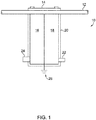
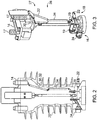
- Line post sensor 10 includes a clamp 14, a voltage current sensor 16, a voltage line sensor 18 and a body 20.
- Clamp 14 is constructed to physically clamp high voltage line post sensor 10 to high voltage power transmission line 12, and to electrically couple line post sensor 10 to high voltage power transmission line 12.
- Voltage line sensor 18 is electrically coupled to high voltage power transmission line 12 and is constructed to measure the voltage in high voltage power transmission line 12.
- An electrical connector or socket 22 is electrically coupled to voltage line sensor 18 and constructed to electrically couple voltage line sensor 18 to a sensor line (not shown) for transmitting the output of voltage line sensor 18 to a receiving unit or measuring device (not shown).
- Voltage current sensor 16 is constructed to measure current in the high voltage power transmission line 12.
- An electrical connector or socket 24 is electrically coupled to voltage current sensor 16 and constructed to electrically couple voltage current sensor 16 to a sensor line (not shown) for transmitting the output of voltage current sensor 16 to a receiving unit or measurement device (not shown).
- Voltage line sensor 18 and voltage current sensor 16 are electrically coupled to a reference voltage, e.g., ground 26.
- Body 20 is constructed to surround and encase voltage line sensor 18 and voltage current sensor 16, and to partially surround and partially encase socket 22 and socket 24.
- voltage current sensor 16 is constructed to sense or measure the current in high voltage power transmission line 12.
- Voltage current sensor 16 includes coils 17 disposed adjacent to high voltage power transmission line 12 and electrically coupled to a low voltage circuit 19. Coils 17 are constructed to sense current in high voltage power transmission line 12.
- Low voltage circuit 19 is constructed to output a low voltage proportional to the current flow in high power transmission line 12.
- the output voltage may be in the range of 0-10 volts to reflect a current in the range of 0-2000 amperes. In other embodiments, the voltage and/or current ranges may vary with the needs of the particular application.
- the voltage range may be 0-120 V to reflect the current flow between 0 and a maximum current flow in high voltage power transmission line 12.
- Low voltage circuit 19 is electrically coupled to electrical connector or socket 24, and the output of low voltage circuit 19 is provided at electrical connector or socket 24, e.g., for measurement by another device.
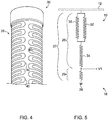
- Voltage line sensor 18 is constructed to sense or measure the voltage in high voltage power transmission line 12. Voltage line sensor 18 is electrically coupled to high voltage power transmission line 12. Voltage line sensor 18 includes a resistive voltage divider 27 formed of a high voltage high resistance circuit 28 and a low voltage low resistance circuit 29. High voltage high resistance circuit 28 is coupled in series between high voltage power transmission line 12 and low voltage low resistance circuit 29. High voltage high resistance circuit 28 includes a plurality of high voltage high resistance resistors 30, 32 and 34. The number of high voltage high resistance resistors may vary with the needs of the application. In one form, high voltage high resistance resistors 30, 32 and 34 are serpentine resistors, e.g., as depicted in FIG. 4 which illustrates a portion of high voltage high resistance resistor 30. The resistive material of high voltage resistors 30, 32 and 34 is formed into a serpentine pattern 38 made of a plurality of switchbacks or undulations 40 that provide a continuous high resistance path.
- the voltage across low voltage low resistance circuit 29 is monitored, and the ratio of the resistances (the resistance of high voltage high resistance circuit 28, in ratio with the resistance of low voltage low resistance circuit 29) is used to determine the voltage level in high voltage power transmission line 12.
- This system provides low energy coupling, but enough output for reading by receiving devices such as electronic meters.
- the high voltage high resistance resistors 30, 32 and 34 are made in serpentine pattern 38 to reduce the inductance of the resistive divider and create long resistive paths.
- the reduction in inductance of the resistive divider reduces the phase error of the measurement.
- a single high voltage high resistance resistor may be coupled to the high voltage power transmission line, i.e., between the high voltage power transmission line and a low voltage low resistance circuit.
- stray capacitance along the high voltage high resistance resistor coupled directly to the high voltage power transmission line increases stray capacitance along the high voltage high resistance resistor coupled directly to the high voltage power transmission line.
- the high frequency voltage distribution along the length of resistive divider becomes nonlinear. This voltage distribution is exponential, and causes high stresses at the ends of the resistive voltage divider, particularly the end of the resistor coupled to the high voltage power transmission line, leading to premature failure of sensor that use a single high voltage high resistance resistor coupled to the high voltage power transmission line.
- the voltage distribution along the high voltage high resistance resistor is an exponential pattern causing very high stresses on the first one or more undulations of the serpentine pattern adjacent to the high voltage power transmission line. This in turn causes a flash over between the undulations, which lowers the high resistance value of the high voltage high resistance resistor, and results in a different ratio of resistances, causing an inaccurate reading from the sensor. The problem worsens as the number of strikes or transient over-voltage increases, ultimately causing premature failure of the sensor.
- the characteristic impedance of the sensor is lowered, which in turn reduces the refraction part of transient over-voltages. This significantly reduces the stresses on the first few serpentine patterns of the high voltage resistors.
- the characteristic impedance is lowered by using two or more high voltage resistors, e.g., similar high voltage resistors, in parallel. By separating the paths of the pulses, the transient over-voltage is halved.
- voltage line sensor 18 includes high voltage high resistance circuit 28 formed of a plurality of a plurality of high voltage high resistance resistors coupled to high voltage power transmission line 12 in parallel with each other.
- high voltage high resistance resistors 30, 32 may be coupled to high voltage power transmission line 12.
- each of high voltage high resistance resistors 30 and 32 have the same electrical resistance. In other embodiments, they may have different resistance values.
- the plurality may include more than two high voltage high resistance resistors coupled to high voltage power transmission line 12 in parallel with each other.
- Low voltage low resistance circuit 29 is coupled in series between the high voltage high resistance circuit 28 and the reference voltage, e.g., ground 26.
- low voltage low resistance circuit 29 may be coupled in series between the plurality of parallel high voltage high resistance resistors and the reference voltage.
- Low voltage low resistance circuit 29 is constructed to output, e.g., via connector or socket 22, a low voltage proportional to the voltage in high voltage power transmission line 12.
- Low voltage low resistance circuit 29 is electrically coupled to electrical connector or socket 22, and the output of low voltage low resistance circuit 29 is provided at electrical connector or socket 22, e.g., for measurement by another device, such as an electronic meter (not shown).
- high voltage high resistance circuit 28 may also include one or more high voltage high resistance resistors coupled in series to the parallel coupled high voltage high resistance resistors.
- high voltage high resistance resistor 34 is coupled in series to the parallel coupled high voltage high resistance resistors 30, 32 at one end, and is coupled in series to low voltage low resistance circuit 29 at the other end, i.e., is coupled in series between parallel coupled high voltage high resistance resistors 30, 32 and low voltage low resistance circuit 29.
- low voltage low resistance circuit 29 is coupled in series between high voltage high resistance resistor 34 and the reference voltage, e.g., ground 26.
- low voltage low resistance circuit 29 may be coupled directly to high voltage high resistance resistors 30, 32 without the intervening high voltage high resistance resistor 34.
- body 20 surrounds and encases high voltage high resistance circuit 28, e.g., the plurality of high voltage high resistance resistors coupled in parallel (e.g., high voltage high resistance resistors 30, 32) and the high voltage high resistance resistor (e.g., high voltage high resistance resistor 34), and also surrounds and encases the low voltage low resistance circuit 29.
- body 20 is an epoxy casting, e.g., wherein high voltage high resistance resistors 30, 32 and 34, and low voltage low resistance circuit 29 are cast into body 20.
- body 20 may take other forms and/or may be formed of other materials.
- coils 17 and low voltage circuit 19 may also be cast into body 20.
- FIG. 5 some aspects of a non-limiting example of line post sensor 10 are illustrated in accordance with an embodiment of the present invention in the form of a circuit diagram.
- high voltage high resistance circuit 28 with high voltage high resistance resistors 30, 32 and 34, and low voltage low resistance circuit 29 are illustrated.
- High voltage high resistance resistors 30, 32 are coupled to high voltage power transmission line 12 in parallel to each other.
- Low voltage low resistance circuit 29 is coupled to the reference voltage, e.g., ground 26.
- High voltage high resistance resistor 34 is coupled in series between low voltage low resistance circuit 29 and high voltage high resistance resistors 30, 32 coupled in parallel.
- the voltage across low voltage low resistance circuit 29 is proportional to the voltage in high voltage power transmission line 12, i.e., based on the resistance of the resistive voltage divider 27 formed by the high voltage high resistance circuit 28 (e.g., high voltage high resistance resistors 30, 32, 34) and the low voltage low resistance circuit 29.
- This voltage may be measured by electrically coupling a voltage measurement device, e.g., electronic meter (not shown), to electrical connector or socket 22 to obtain the voltage V1 with respect to the reference voltage, e.g., ground 26.
- the electrical resistance of low voltage low resistance circuit 29 is set or adjusted to achieve a desired voltage output at the rated or maximum voltage of high voltage power transmission line 12, e.g., 35 kV, based the resistance of high voltage high resistance circuit 28.
- the output voltage range is set to 0-10 V for a high voltage power transmission line 12 voltage range of 0 V to 35 kV, e.g., a maximum voltage differential of 10 V.
- the maximum voltage differential occurs at the maximum voltage of high voltage power transmission line 12.
- the output voltage range may be 0-120 V, e.g., a maximum voltage differential of 120 V.
- the voltage differential may be a different value and may be in a different voltage range.
- the electrical resistance of low voltage low resistance circuit 29 is a resistance value in the range of 10k Ohms to 500k Ohms to achieve a suitable output voltage range. In other embodiments, the electrical resistance of low voltage low resistance circuit 29 may be a resistance value in the range of 5k Ohms to 1000k Ohms. In still other embodiments the electrical resistance of low voltage low resistance circuit 29 may be another range or value.
- High voltage high resistance circuit 28 operate across much higher voltage differentials than does low voltage low resistance circuit 29. For example, for a 35 kV system, in some embodiments, high voltage high resistance circuit 28 operates across a voltage differential of at least 34.9 kV. As another example, for a 10 kV system, in some embodiments, high voltage high resistance circuit 28 operates across a voltage differential of at least 9.9 kV. In one non-limiting example, the resistance of high voltage high resistance resistors 30, 32 and 34 is 20M Ohm, e.g., for a 35 kV voltage in high voltage power transmission line 12.
- the voltage drop across high voltage high resistance resistors 30, 32 is slightly less than one third of the voltage differential between high voltage power transmission line 12, and the voltage drop across high voltage high resistance resistor 34 is slightly less than two thirds of the voltage differential between high voltage power transmission line 12, with the difference in voltage drop occurring across low voltage low resistance circuit 29.
- the voltage drop across high voltage high resistance resistors 30, 32 is at least 11.5 kV, and the voltage drop across high voltage high resistance resistor 34 is at least 23 kV.
- the resistance value for the high voltage high resistance resistors may vary with the needs of the application.
- Embodiments of the present invention include a high voltage line post sensor for a high voltage power distribution system having a high voltage power transmission line for transmitting electrical power at a high voltage, comprising: a voltage line sensor, comprising: a high voltage high resistance circuit including a first high voltage high resistance resistor coupled to the high voltage power transmission line and a second high voltage high resistance resistor coupled to the high voltage power transmission line in parallel to the first resistor; and a low voltage low resistance circuit coupled in series between the high voltage high resistance circuit and a reference voltage; and a body surrounding and encasing the high voltage high resistance circuit and the low voltage low resistance circuit.
- the voltage line sensor includes a resistive voltage divider formed by the high voltage high resistance circuit and the low voltage low resistance circuit.
- each of the first high voltage high resistance resistor and the second high voltage high resistance resistor are each constructed to operate across at least an 11.5 kV voltage differential for a 35 kV high voltage power transmission line.
- the high voltage high resistance circuit further includes a third high voltage high resistance resistor coupled in series to the first high voltage resistor and the second high voltage resistor, and coupled in series to the low voltage low resistance circuit.
- the third high voltage high resistance resistor has a resistance of 20M Ohms.
- the third high voltage high resistance resistor is constructed to operate across at least a 23 kV voltage differential for a 35 kV high voltage power transmission line.
- first high voltage high resistance resistor and the second high voltage high resistance resistor each have the same resistance.
- the first high voltage high resistance resistor and the second high voltage high resistance resistor each have a resistance of at least 20M Ohms.
- the low voltage low resistance circuit operates across a maximum voltage differential having a voltage value in the range from 10 V to 120 V.
- the low voltage low resistance circuit has a resistance in the range of 10k Ohms to 500k Ohms.
- Embodiments of the present invention include a high voltage line post sensor for a high voltage power distribution system having a high voltage power transmission line for transmitting electrical power at a high voltage, comprising: a clamp for clamping the high voltage line post sensor to the high voltage power transmission line and electrically coupling the line post sensor to the high voltage power transmission line; a voltage line sensor electrically coupled to the high voltage power transmission line and constructed to measure the voltage in the high voltage power transmission line, the voltage line sensor comprising: a plurality of first high voltage high resistance resistors coupled in parallel to the high voltage power transmission line; a second high voltage high resistance resistor coupled in series to the plurality of high voltage high resistance resistors; and a low voltage low resistance circuit coupled in series between the second high voltage high resistance resistor and a reference voltage, wherein the low voltage low resistance circuit is constructed to output a low voltage proportional to the voltage in the high voltage power transmission line; and a body surrounding and encasing the plurality of high voltage high resistance resistors coupled in parallel, the high voltage high resistance resistor
- the plurality of first high voltage high resistance resistors and the second high voltage high resistance resistor form a high voltage high resistance circuit
- the voltage line sensor includes a resistive voltage divider formed by the high voltage high resistance circuit and the low voltage low resistance circuit.
- the high voltage line post sensor further comprises a voltage current sensor constructed to measure a current in the high voltage power transmission line.
- the voltage current sensor includes a coil constructed to sense current in the high voltage power transmission line; and a low voltage circuit constructed to output a voltage proportional to the current.
- the body is an epoxy casting.
- the plurality of first high voltage high resistance resistors and the second high voltage high resistance resistor are cast into the body.
- the plurality of first high voltage high resistance resistors are serpentine resistors.
- the second high voltage high resistance resistor is a serpentine resistor.
- the reference voltage is ground.
Landscapes
- Physics & Mathematics (AREA)
- General Physics & Mathematics (AREA)
- Measuring Instrument Details And Bridges, And Automatic Balancing Devices (AREA)
Applications Claiming Priority (1)
| Application Number | Priority Date | Filing Date | Title |
|---|---|---|---|
| US16/213,755 US11125782B2 (en) | 2018-12-07 | 2018-12-07 | Line post sensor |
Publications (1)
| Publication Number | Publication Date |
|---|---|
| EP3663776A1 true EP3663776A1 (de) | 2020-06-10 |
Family
ID=68808192
Family Applications (1)
| Application Number | Title | Priority Date | Filing Date |
|---|---|---|---|
| EP19214145.5A Pending EP3663776A1 (de) | 2018-12-07 | 2019-12-06 | Leitungspfostensensor |
Country Status (2)
| Country | Link |
|---|---|
| US (1) | US11125782B2 (de) |
| EP (1) | EP3663776A1 (de) |
Families Citing this family (2)
| Publication number | Priority date | Publication date | Assignee | Title |
|---|---|---|---|---|
| WO2023017737A1 (ja) * | 2021-08-10 | 2023-02-16 | 日置電機株式会社 | プローブ装置 |
| EP4425191A1 (de) * | 2023-02-28 | 2024-09-04 | Arteche Centro de Tecnologia, A.I.E. | Abgeschirmter spannungsteiler |
Citations (15)
| Publication number | Priority date | Publication date | Assignee | Title |
|---|---|---|---|---|
| US5181026A (en) * | 1990-01-12 | 1993-01-19 | Granville Group, Inc., The | Power transmission line monitoring system |
| EP0678956A1 (de) * | 1994-04-18 | 1995-10-25 | ABBPATENT GmbH | Strom- und Spannungssensor für ein Hochspannungsfeld |
| US5698831A (en) * | 1993-04-29 | 1997-12-16 | Lindsey Manufacturing Company | Integrated electrical system |
| DE19719521A1 (de) * | 1997-05-09 | 1998-11-19 | Felten & Guilleaume Energie | Spannungssensor für Meß- und Schutzwerke für Mittelspannungsschaltanlagen |
| US5883508A (en) * | 1995-03-13 | 1999-03-16 | Duromer Kunststoffverarbeitungs-Gmbh | Voltage transformer with voltage divider for measuring voltage in medium high and high voltage installations |
| US20020093326A1 (en) * | 2001-01-18 | 2002-07-18 | Bierer Walter S. | AC phasing voltmeter |
| US6717395B2 (en) * | 2001-05-31 | 2004-04-06 | Mcgraw-Edison Company | Current transformer based high voltage measurement apparatus |
| WO2004081589A1 (en) * | 2003-03-13 | 2004-09-23 | Canterprise Limited | High-voltage measurement device |
| US20060012382A1 (en) * | 2004-07-19 | 2006-01-19 | Fieldmetrics Inc | Modular voltage sensor |
| EP1882954A1 (de) * | 2006-07-25 | 2008-01-30 | Alstom Transport S.A. | Vorrichtung zur Messung der an eine Eisenbahnlokomotive gelieferten elektrischen Energie |
| FR2965058A1 (fr) * | 2010-09-16 | 2012-03-23 | Mobile Comfort Holding | Compteur d'energie active et reactive bidirectionnelle pour vehicule ferroviaire |
| WO2012113575A2 (en) * | 2011-02-25 | 2012-08-30 | Abb Ag | Resistive structure and resistive voltage divider arrangement |
| US20140207399A1 (en) * | 2013-01-24 | 2014-07-24 | Hershel Roberson | System and Method for Monitoring a Power Line |
| CN106546790A (zh) * | 2016-11-25 | 2017-03-29 | 云南电网有限责任公司电力科学研究院 | 一种差分结构电阻分压器 |
| US20180136256A1 (en) * | 2015-06-15 | 2018-05-17 | Casram Rail S.P.A. | Device for measuring the electric power drawn by a railway vehicle from a high-voltage electric supply line |
Family Cites Families (11)
| Publication number | Priority date | Publication date | Assignee | Title |
|---|---|---|---|---|
| DE2363933C3 (de) | 1973-12-20 | 1980-09-04 | Siemens Ag, 1000 Berlin Und 8000 Muenchen | Kombinierte Strom- und Spannungsmeßeinrichtung |
| US4158810A (en) | 1974-10-21 | 1979-06-19 | Leskovar Silvin M | Telemetering post for measuring variables in a high-voltage overhead line |
| US4243970A (en) * | 1979-04-06 | 1981-01-06 | Hardee Patrick C | Open circuit alarm |
| US5017859A (en) | 1989-08-03 | 1991-05-21 | Westinghouse Electric Corp. | Integral capacitive divider bus bar voltage measuring apparatus and combined current sensor |
| US5136234A (en) * | 1990-10-04 | 1992-08-04 | Hastings Fiber Glass Products, Inc. | Digital high-voltage meter device |
| DE4121654A1 (de) | 1991-06-29 | 1993-01-07 | Asea Brown Boveri | Kombinierter strom- und spannungswandler fuer eine metallgekapselte gasisolierte hochspannungsanlage |
| US5424663A (en) | 1993-04-22 | 1995-06-13 | North American Philips Corporation | Integrated high voltage differential sensor using the inverse gain of high voltage transistors |
| US7079004B2 (en) * | 2003-10-10 | 2006-07-18 | Agilent Technologies, Inc. | Precision thin film AC voltage divider |
| WO2010019441A1 (en) * | 2008-08-14 | 2010-02-18 | Nantero, Inc. | Nonvolatile nanotube programmable logic devices and field programmable gate array |
| US8767071B1 (en) | 2011-03-03 | 2014-07-01 | The United States Of America As Represented By The Secretary Of The Air Force | High voltage power line multi-sensor system |
| US10983173B2 (en) * | 2018-07-13 | 2021-04-20 | Lindsey Manufacturing Co. | Active current monitor |
-
2018
- 2018-12-07 US US16/213,755 patent/US11125782B2/en active Active
-
2019
- 2019-12-06 EP EP19214145.5A patent/EP3663776A1/de active Pending
Patent Citations (15)
| Publication number | Priority date | Publication date | Assignee | Title |
|---|---|---|---|---|
| US5181026A (en) * | 1990-01-12 | 1993-01-19 | Granville Group, Inc., The | Power transmission line monitoring system |
| US5698831A (en) * | 1993-04-29 | 1997-12-16 | Lindsey Manufacturing Company | Integrated electrical system |
| EP0678956A1 (de) * | 1994-04-18 | 1995-10-25 | ABBPATENT GmbH | Strom- und Spannungssensor für ein Hochspannungsfeld |
| US5883508A (en) * | 1995-03-13 | 1999-03-16 | Duromer Kunststoffverarbeitungs-Gmbh | Voltage transformer with voltage divider for measuring voltage in medium high and high voltage installations |
| DE19719521A1 (de) * | 1997-05-09 | 1998-11-19 | Felten & Guilleaume Energie | Spannungssensor für Meß- und Schutzwerke für Mittelspannungsschaltanlagen |
| US20020093326A1 (en) * | 2001-01-18 | 2002-07-18 | Bierer Walter S. | AC phasing voltmeter |
| US6717395B2 (en) * | 2001-05-31 | 2004-04-06 | Mcgraw-Edison Company | Current transformer based high voltage measurement apparatus |
| WO2004081589A1 (en) * | 2003-03-13 | 2004-09-23 | Canterprise Limited | High-voltage measurement device |
| US20060012382A1 (en) * | 2004-07-19 | 2006-01-19 | Fieldmetrics Inc | Modular voltage sensor |
| EP1882954A1 (de) * | 2006-07-25 | 2008-01-30 | Alstom Transport S.A. | Vorrichtung zur Messung der an eine Eisenbahnlokomotive gelieferten elektrischen Energie |
| FR2965058A1 (fr) * | 2010-09-16 | 2012-03-23 | Mobile Comfort Holding | Compteur d'energie active et reactive bidirectionnelle pour vehicule ferroviaire |
| WO2012113575A2 (en) * | 2011-02-25 | 2012-08-30 | Abb Ag | Resistive structure and resistive voltage divider arrangement |
| US20140207399A1 (en) * | 2013-01-24 | 2014-07-24 | Hershel Roberson | System and Method for Monitoring a Power Line |
| US20180136256A1 (en) * | 2015-06-15 | 2018-05-17 | Casram Rail S.P.A. | Device for measuring the electric power drawn by a railway vehicle from a high-voltage electric supply line |
| CN106546790A (zh) * | 2016-11-25 | 2017-03-29 | 云南电网有限责任公司电力科学研究院 | 一种差分结构电阻分压器 |
Non-Patent Citations (2)
| Title |
|---|
| MEREV A ET AL: "The construction of a DC high voltage precision divider", JOURNAL OF ELECTROSTATICS, ELSEVIER SCIENCE PUBLISHERS B.V. AMSTERDAM, NL, vol. 67, no. 5, 1 September 2009 (2009-09-01), pages 741 - 745, XP026574428, ISSN: 0304-3886, [retrieved on 20090509], DOI: 10.1016/J.ELSTAT.2009.04.001 * |
| YI LI ET AL: "Development of Precision DC High-Voltage Dividers", IEEE TRANSACTIONS ON INSTRUMENTATION AND MEASUREMENT, IEEE SERVICE CENTER, PISCATAWAY, NJ, US, vol. 60, no. 7, 1 July 2011 (2011-07-01), pages 2211 - 2216, XP011326385, ISSN: 0018-9456, DOI: 10.1109/TIM.2010.2100655 * |
Also Published As
| Publication number | Publication date |
|---|---|
| US11125782B2 (en) | 2021-09-21 |
| US20200182910A1 (en) | 2020-06-11 |
Similar Documents
| Publication | Publication Date | Title |
|---|---|---|
| US7129693B2 (en) | Modular voltage sensor | |
| US6822463B1 (en) | Active differential test probe with a transmission line input structure | |
| US11125782B2 (en) | Line post sensor | |
| US4887028A (en) | Watthour meter with isolation transformers having a feedback loop | |
| CN104459276A (zh) | 一种测量纳秒脉冲电流的罗氏线圈 | |
| CN103682862B (zh) | 一种环网柜电缆插接件 | |
| US10942201B2 (en) | Current detector and current meter | |
| US7449637B2 (en) | Pulse current sensor | |
| US8692541B2 (en) | Position sensing head with redundancy | |
| US2497094A (en) | Microwave apparatus | |
| CN102539888A (zh) | 直测电容电流型一次电压传感器 | |
| CN107407701B (zh) | 用于高阻抗电压传感器的虚地感测电路 | |
| CN108226602B (zh) | 用于测量交流电的时间导数的方法和传感器 | |
| US3611123A (en) | Low insertion loss directional detector | |
| US2654066A (en) | Q meter | |
| CN102928646A (zh) | 以氧化锌电阻作为分压器件的电压传感器及其应用 | |
| US3447083A (en) | Electrical power metering device for insertion in a transmission line | |
| CN218546860U (zh) | 一种电流信号采集电路及电流采集器 | |
| CN109030852B (zh) | 一种压电式核电磁脉冲隔离装置 | |
| CN207133345U (zh) | 一种电压传感器 | |
| US2852741A (en) | Directional wattmeter | |
| US3500197A (en) | Integrated high voltage transformer and capacitor divider | |
| US3492569A (en) | Bridge circuit network for measurement of reflection coefficients | |
| CN108254600B (zh) | 电能表 | |
| CN209168844U (zh) | 防高频谐振压敏电阻器以及其防护滤波电路 |
Legal Events
| Date | Code | Title | Description |
|---|---|---|---|
| PUAI | Public reference made under article 153(3) epc to a published international application that has entered the european phase |
Free format text: ORIGINAL CODE: 0009012 |
|
| STAA | Information on the status of an ep patent application or granted ep patent |
Free format text: STATUS: THE APPLICATION HAS BEEN PUBLISHED |
|
| AK | Designated contracting states |
Kind code of ref document: A1 Designated state(s): AL AT BE BG CH CY CZ DE DK EE ES FI FR GB GR HR HU IE IS IT LI LT LU LV MC MK MT NL NO PL PT RO RS SE SI SK SM TR |
|
| AX | Request for extension of the european patent |
Extension state: BA ME |
|
| STAA | Information on the status of an ep patent application or granted ep patent |
Free format text: STATUS: REQUEST FOR EXAMINATION WAS MADE |
|
| 17P | Request for examination filed |
Effective date: 20201210 |
|
| RBV | Designated contracting states (corrected) |
Designated state(s): AL AT BE BG CH CY CZ DE DK EE ES FI FR GB GR HR HU IE IS IT LI LT LU LV MC MK MT NL NO PL PT RO RS SE SI SK SM TR |
|
| RAP3 | Party data changed (applicant data changed or rights of an application transferred) |
Owner name: ABB SCHWEIZ AG Owner name: HITACHI ENERGY SWITZERLAND AG |
|
| STAA | Information on the status of an ep patent application or granted ep patent |
Free format text: STATUS: EXAMINATION IS IN PROGRESS |
|
| 17Q | First examination report despatched |
Effective date: 20230103 |
|
| GRAP | Despatch of communication of intention to grant a patent |
Free format text: ORIGINAL CODE: EPIDOSNIGR1 |
|
| STAA | Information on the status of an ep patent application or granted ep patent |
Free format text: STATUS: GRANT OF PATENT IS INTENDED |
|
| INTG | Intention to grant announced |
Effective date: 20260114 |