EP3663771A1 - Procédé et système de détection d'un vent dans une zone géographique - Google Patents
Procédé et système de détection d'un vent dans une zone géographique Download PDFInfo
- Publication number
- EP3663771A1 EP3663771A1 EP19211353.8A EP19211353A EP3663771A1 EP 3663771 A1 EP3663771 A1 EP 3663771A1 EP 19211353 A EP19211353 A EP 19211353A EP 3663771 A1 EP3663771 A1 EP 3663771A1
- Authority
- EP
- European Patent Office
- Prior art keywords
- wind
- vehicle
- data
- speed
- determined
- Prior art date
- Legal status (The legal status is an assumption and is not a legal conclusion. Google has not performed a legal analysis and makes no representation as to the accuracy of the status listed.)
- Withdrawn
Links
- 238000000034 method Methods 0.000 title claims abstract description 76
- 238000001514 detection method Methods 0.000 claims abstract description 23
- 238000011156 evaluation Methods 0.000 claims abstract description 15
- 230000000694 effects Effects 0.000 description 10
- 230000005484 gravity Effects 0.000 description 10
- 238000005259 measurement Methods 0.000 description 9
- 238000005265 energy consumption Methods 0.000 description 8
- 230000001133 acceleration Effects 0.000 description 7
- 238000004364 calculation method Methods 0.000 description 7
- 230000005540 biological transmission Effects 0.000 description 6
- 238000011161 development Methods 0.000 description 5
- 230000018109 developmental process Effects 0.000 description 5
- 238000005520 cutting process Methods 0.000 description 4
- 238000005096 rolling process Methods 0.000 description 4
- 230000001419 dependent effect Effects 0.000 description 3
- 230000006870 function Effects 0.000 description 3
- 238000012545 processing Methods 0.000 description 3
- 238000002604 ultrasonography Methods 0.000 description 3
- 238000004458 analytical method Methods 0.000 description 2
- 238000013459 approach Methods 0.000 description 2
- 238000006243 chemical reaction Methods 0.000 description 2
- 238000004891 communication Methods 0.000 description 2
- 238000013213 extrapolation Methods 0.000 description 2
- 238000010801 machine learning Methods 0.000 description 2
- 238000012546 transfer Methods 0.000 description 2
- 102000007620 Pulmonary Surfactant-Associated Protein C Human genes 0.000 description 1
- 108010007125 Pulmonary Surfactant-Associated Protein C Proteins 0.000 description 1
- 238000007664 blowing Methods 0.000 description 1
- 230000037237 body shape Effects 0.000 description 1
- 238000012937 correction Methods 0.000 description 1
- 238000013461 design Methods 0.000 description 1
- 238000009826 distribution Methods 0.000 description 1
- 238000004146 energy storage Methods 0.000 description 1
- 238000005516 engineering process Methods 0.000 description 1
- 238000001914 filtration Methods 0.000 description 1
- 239000000446 fuel Substances 0.000 description 1
- 230000001771 impaired effect Effects 0.000 description 1
- 230000010365 information processing Effects 0.000 description 1
- 230000003287 optical effect Effects 0.000 description 1
- 230000002787 reinforcement Effects 0.000 description 1
- 238000007619 statistical method Methods 0.000 description 1
- 238000009423 ventilation Methods 0.000 description 1
Images


Classifications
-
- G—PHYSICS
- G01—MEASURING; TESTING
- G01P—MEASURING LINEAR OR ANGULAR SPEED, ACCELERATION, DECELERATION, OR SHOCK; INDICATING PRESENCE, ABSENCE, OR DIRECTION, OF MOVEMENT
- G01P5/00—Measuring speed of fluids, e.g. of air stream; Measuring speed of bodies relative to fluids, e.g. of ship, of aircraft
-
- B—PERFORMING OPERATIONS; TRANSPORTING
- B60—VEHICLES IN GENERAL
- B60W—CONJOINT CONTROL OF VEHICLE SUB-UNITS OF DIFFERENT TYPE OR DIFFERENT FUNCTION; CONTROL SYSTEMS SPECIALLY ADAPTED FOR HYBRID VEHICLES; ROAD VEHICLE DRIVE CONTROL SYSTEMS FOR PURPOSES NOT RELATED TO THE CONTROL OF A PARTICULAR SUB-UNIT
- B60W40/00—Estimation or calculation of non-directly measurable driving parameters for road vehicle drive control systems not related to the control of a particular sub unit, e.g. by using mathematical models
- B60W40/02—Estimation or calculation of non-directly measurable driving parameters for road vehicle drive control systems not related to the control of a particular sub unit, e.g. by using mathematical models related to ambient conditions
-
- G—PHYSICS
- G01—MEASURING; TESTING
- G01P—MEASURING LINEAR OR ANGULAR SPEED, ACCELERATION, DECELERATION, OR SHOCK; INDICATING PRESENCE, ABSENCE, OR DIRECTION, OF MOVEMENT
- G01P13/00—Indicating or recording presence, absence, or direction, of movement
- G01P13/02—Indicating direction only, e.g. by weather vane
-
- G—PHYSICS
- G01—MEASURING; TESTING
- G01P—MEASURING LINEAR OR ANGULAR SPEED, ACCELERATION, DECELERATION, OR SHOCK; INDICATING PRESENCE, ABSENCE, OR DIRECTION, OF MOVEMENT
- G01P5/00—Measuring speed of fluids, e.g. of air stream; Measuring speed of bodies relative to fluids, e.g. of ship, of aircraft
- G01P5/02—Measuring speed of fluids, e.g. of air stream; Measuring speed of bodies relative to fluids, e.g. of ship, of aircraft by measuring forces exerted by the fluid on solid bodies, e.g. anemometer
-
- B—PERFORMING OPERATIONS; TRANSPORTING
- B60—VEHICLES IN GENERAL
- B60W—CONJOINT CONTROL OF VEHICLE SUB-UNITS OF DIFFERENT TYPE OR DIFFERENT FUNCTION; CONTROL SYSTEMS SPECIALLY ADAPTED FOR HYBRID VEHICLES; ROAD VEHICLE DRIVE CONTROL SYSTEMS FOR PURPOSES NOT RELATED TO THE CONTROL OF A PARTICULAR SUB-UNIT
- B60W2510/00—Input parameters relating to a particular sub-units
- B60W2510/10—Change speed gearings
- B60W2510/106—Output power
-
- B—PERFORMING OPERATIONS; TRANSPORTING
- B60—VEHICLES IN GENERAL
- B60W—CONJOINT CONTROL OF VEHICLE SUB-UNITS OF DIFFERENT TYPE OR DIFFERENT FUNCTION; CONTROL SYSTEMS SPECIALLY ADAPTED FOR HYBRID VEHICLES; ROAD VEHICLE DRIVE CONTROL SYSTEMS FOR PURPOSES NOT RELATED TO THE CONTROL OF A PARTICULAR SUB-UNIT
- B60W2552/00—Input parameters relating to infrastructure
- B60W2552/15—Road slope, i.e. the inclination of a road segment in the longitudinal direction
-
- B—PERFORMING OPERATIONS; TRANSPORTING
- B60—VEHICLES IN GENERAL
- B60W—CONJOINT CONTROL OF VEHICLE SUB-UNITS OF DIFFERENT TYPE OR DIFFERENT FUNCTION; CONTROL SYSTEMS SPECIALLY ADAPTED FOR HYBRID VEHICLES; ROAD VEHICLE DRIVE CONTROL SYSTEMS FOR PURPOSES NOT RELATED TO THE CONTROL OF A PARTICULAR SUB-UNIT
- B60W2556/00—Input parameters relating to data
- B60W2556/05—Big data
-
- B—PERFORMING OPERATIONS; TRANSPORTING
- B60—VEHICLES IN GENERAL
- B60W—CONJOINT CONTROL OF VEHICLE SUB-UNITS OF DIFFERENT TYPE OR DIFFERENT FUNCTION; CONTROL SYSTEMS SPECIALLY ADAPTED FOR HYBRID VEHICLES; ROAD VEHICLE DRIVE CONTROL SYSTEMS FOR PURPOSES NOT RELATED TO THE CONTROL OF A PARTICULAR SUB-UNIT
- B60W2556/00—Input parameters relating to data
- B60W2556/45—External transmission of data to or from the vehicle
- B60W2556/50—External transmission of data to or from the vehicle of positioning data, e.g. GPS [Global Positioning System] data
Definitions
- the present invention relates to a method and a system for detecting a wind in a geographical area.
- the influencing factors on the basis of which an energy requirement can be predicted when driving a vehicle include the speed and direction of the wind in the area of the vehicle. Since the air resistance increases quadratically with the speed of the vehicle relative to the surrounding air, even lower wind speeds can have a noticeable impact on energy consumption.
- weather maps from weather services are currently available, but they offer a rather low local resolution and describe the wind conditions well above the height of about 0 to 2 m above the ground relevant for vehicles.
- Different solutions have been proposed to take wind conditions into account when driving a vehicle: For example, the DE 10 2010 039 569 A1 a method for determining energy expenditure information for a journey of a land vehicle. A force effect of a wind with respect to the land vehicle is determined on the basis of navigation information and wind information.
- the US 2012/0310536 A1 proposes a weather information processing system in which a vehicle measures weather information and registers changes. The vehicle can exchange information about changes in the weather with other vehicles.
- the one in the DE 101 62 335 A1 The methods described for generating and updating a route and / or road condition map are dynamically recorded by means of weather-related status data and transmitted to a central computer, which uses this data to determine traffic-relevant road conditions.
- the DE 10 2016 223 299 A1 describes a method in which a driving strategy is selected as a function of a wind that is predicted to act on a vehicle.
- a rotor of a motor fan is used to determine the wind speed along the direction of travel of a moving vehicle.
- EP 2 591 967 A2 describes a method for operating a vehicle, the movement of the vehicle being observed when coasting and driving resistance values being determined.
- a component of the wind speed vector that runs parallel to the direction of movement can be detected. If measurements are available in different directions, such as a curve, the amount and direction of a wind speed can be determined.
- movements in several different directions of travel are recorded in the geographical area for at least one vehicle.
- the direction of travel and a drive power for driving the vehicle are recorded for each of the movements, and a wind speed and a wind direction of the wind are determined on the basis of the recorded drive powers and directions of travel.
- the method advantageously takes advantage of the fact that a wind acting on the vehicle has an effect on the drive power required. Information about this, in particular about the energy or fuel consumption at a certain speed, is typically readily available in the vehicle.
- the influence of the wind on the movement and drive of the vehicle varies with the angle of attack, in extreme cases through headwind or tailwind. The comparison of data for different directions of travel therefore enables the wind direction to be determined.
- wind is understood to mean in particular an air flow which acts on the vehicle.
- a "true wind”, which denotes the movement of the air relative to the earth's surface, and a “apparent wind”, which denotes the movement of the air relative to the vehicle, can be distinguished.
- the movement of the "apparent wind” can be described by adding the airflow generated by the movement of the vehicle and the "true wind”.
- the method is particularly concerned with the detection of the "true wind”, which is independent of the movement of the vehicle and is referred to below as “wind”, unless the context otherwise indicates.
- the method assumes that the vehicle is moving within the geographic area for which the wind is to be recorded.
- the position of the vehicle can be recorded in a manner known per se, for example by means of a global navigation satellite system (GNSS), such as the global positioning system (GPS).
- GNSS global navigation satellite system
- GPS global positioning system
- other methods for determining the position can be used, for example by means of landmarks.
- the position can be determined in a global coordinate system or relative to a specific reference point.
- the direction of the vehicle can be detected in various ways known per se.
- a compass or a global navigation satellite system (GNSS) such as GPS can be used.
- the direction of travel can be determined on the basis of map data and a position of the vehicle, for example by locating the vehicle on a specific route or road and analyzing the course of the route.
- the direction can be defined as the direction of movement in a global coordinate system.
- the direction can also be recorded in a relative coordinate system, for example by means of a landmark-based method or by the direction being determined and provided by an external unit.
- the position and direction of the vehicle are determined simultaneously in a specific coordinate system, in particular using the same method.
- the combination of position and direction is called the "pose" of the vehicle.
- a vehicle may move along a non-linear traffic route in the geographic area, it may drive different traffic routes in the area in succession, or multiple vehicles may travel the same non-linear traffic route or the different traffic routes within the geographical area.
- the method also assumes that it is determined that the vehicle is in the geographic area while moving in one direction. This can also be determined using various position determination methods.
- the drive power detected when driving in a certain direction for driving the vehicle relates to the drive power in the direction of travel, so that any additional drive power components that may occur to control the vehicle in the transverse direction, such as when cornering, are not taken into account.
- the direction of travel can in particular run parallel to a longitudinal axis of the vehicle and can also be defined during cornering in such a way that at least one infinitesimally small stretch of road with a straight-ahead direction of travel is assumed at any point along an arbitrarily shaped trajectory.
- the drive power is also recorded in a manner known per se, in particular overall for the entire vehicle or for individual axles or wheels.
- the output power of a device for providing the drive can be measured, for example in the case of an electric motor.
- measuring methods can be used that measure the drive power based on a power transmission through a transmission. The performance results in particular as a product of the speed of the vehicle and the force exerted on the vehicle, in particular in the direction of travel.
- the force for the drive and the current speed of the vehicle can therefore be recorded.
- the drive power can also be recorded when the vehicle is decelerated, that is, when force is exerted against the direction of travel, for example by braking.
- the power converted from the braking process can also be regarded as drive power - in particular with a negative sign - in the sense of the invention.
- a roadway inclination is also detected and taken into account when determining the wind speed and the wind direction becomes. In this way, it can advantageously be determined particularly precisely what proportion of the drive power is caused by the wind and whether the further proportions are based, for example, on a certain slope of the road.
- the inclination of the roadway in particular upwards or downwards along the direction of travel, can be recorded, for example, using map data, but other methods and sensors can also be used alternatively or additionally.
- the inclination of the road has an effect on the power required to drive the vehicle, in particular to reach a certain speed. It can thereby be determined which energy is used to operate the vehicle, and this information can be adjusted for the influence of the road inclination.
- the mass of the vehicle can be determined by various methods.
- the vehicle can have a sensor for measuring the mass.
- a loading of cargo or a sitting of passengers on the seats of the vehicle can be detected.
- Values which indicate the mass of the vehicle can also be predefined, for example by a manufacturer, in particular different values of the mass depending on the driving situation.
- the rolling friction of the vehicle can be taken into account, which can depend on parameters such as a coefficient of friction of the tires and the road surface and can also change dynamically, for example when a tire is worn or a tire is changed.
- the drive power required for a vehicle can also depend on the vehicle type or the outer silhouette of the vehicle, for example due to the different air resistance of different body shapes.
- a conversion step can therefore be provided, by means of which vehicle-specific constants are used to standardize the measured parameters such that the standardized measurement values can be used to determine the wind independently of the specific vehicle.
- Constant parameters for a vehicle can be used for this standardization in order to be able to carry out the actual calculation steps of the method more easily, for example by a unit which is designed independently of the specific vehicle and does not have vehicle-specific parameters.
- the method is carried out by a large number of vehicles.
- the vehicles can advantageously act as a "swarm” and make individual data records of the individual vehicles available to a common vehicle-external unit.
- the latter can store and process the data, in particular by means of "big data” methods, in order to make them available for retrieval if necessary.
- the vehicles can transmit the location-specific wind data determined by them to a central vehicle-external unit or to each other. You can also transfer the parameters measured by you, in particular the recorded longitudinal and lateral control data.
- standardization can be carried out in such a way that the parameters are independent of the specific vehicles, in particular of their external shape and features of the individual drive properties of the vehicles, and can be processed particularly easily without having to know their origin precisely.
- a vehicle In typical road traffic, a vehicle does not move in a particularly large number of directions within a geographical area, but rather along a straight line. This is all the more the case the smaller the geographic area under consideration. In order to be able to determine the information about the wind as precisely and with high resolution in the method, however, small geographic areas should be used to determine the wind. It is therefore very important in the process that the data of several vehicles can be used. This is because they can move in different directions at the same time or at short intervals in the same geographical area, for example in intersection areas, at junctions or in different lanes.
- the wind speed against the direction of travel can be determined for the individual vehicles; the wind direction can then be derived from the distribution of the wind speeds depending on the direction of travel of the vehicles.
- location-related wind data with a wind direction, a wind speed and a position of the vehicle are generated and output.
- the position of the vehicle is determined more precisely than has already been done where the presence of the vehicle in the geographical area has been recorded. This advantageously results in a linkage of the recorded data about the wind with the position of the vehicle.
- the location-related wind data also include, in particular, information about the direction in which the vehicle is moving.
- the location-related wind data can be output, for example, to a driver assistance system or another device of the vehicle, for example a drive control of the vehicle.
- the location-related wind data are transmitted to a unit external to the vehicle and stored there. They can therefore advantageously be stored externally or processed further and, if necessary, also made available to other participants.
- the vehicle-external unit can be, for example, an external server that is at least temporarily connected to the vehicle in terms of data technology.
- the connection is established in a manner known per se, for example using a mobile radio network.
- the vehicle can have its own interface to the vehicle-external unit or can be connected to a further unit, for example a mobile user device in the vehicle, which then establishes the connection to the vehicle-external unit, for example via the Internet.
- Methods of cloud computing can also be used to transmit and process the data provided by the vehicle.
- various steps of processing the recorded data by the vehicles themselves and / or the vehicle-external unit can take place: the entire evaluation of the recorded data and determination of the wind speed and wind direction can take place in the vehicle; The location-related wind data can then already be provided by the vehicle and further distributed by the vehicle-external unit or processed together with further data.
- the processing in the vehicle can also be limited to the fact that the vehicle uses the acquired data to determine the wind speed in the direction of its movement and to transmit this information to the unit external to the vehicle. This can be done for a variety of vehicles.
- the vehicle-external unit can then analyze how the wind speed depends on the direction, and thereby determine the wind direction.
- the recorded data about the drive power and direction in the geographical area, in particular for several vehicles can be transmitted to the external unit.
- the amount of the wind speed that acts along the respective direction of the movement can then be determined there. This can be done in particular for the data of several vehicles.
- the wind direction can also be determined by the Dependence of the wind strength on the direction of movement of the vehicle is determined.
- Largely unprocessed data can be transmitted from the vehicle to the vehicle-external unit and processed by it, which reduces the computing power required in the vehicle.
- the vehicle-external unit uses the stored wind data to generate and provide wind map data. These can advantageously be made available for retrieval by other vehicles and used by them to better control their operation.
- wind map data can be generated and provided by the vehicle, in particular direct communication with other vehicles, for example via Car2Car communication. Data acquired from a large number of vehicles can also be used in this way.
- the wind map data include information about wind speeds and wind directions at a plurality of positions, in particular for a specific point in time or period.
- the spatial resolution depends in particular on the time and / or spatial intervals at which the wind is detected by a single or several vehicles. In particular, a resolution of at least 50m * 50m or finer, preferably at least 20m * 20m or finer, is achieved. Since the wind is recorded in the method on the basis of the data for the longitudinal and lateral control of the moving vehicle, the wind map data can assign the specific parameters of the wind to specific positions of a traffic route traveled, in particular a position along a road.
- the wind map data can be updated regularly or on request based on the data provided by a vehicle or a large number of vehicles. This allows new information about the wind at a certain position to be taken into account. It can be provided, for example, that the vehicles of a vehicle fleet determine location-related wind data at regular intervals and transmit them to the vehicle-external unit. This also determines updated wind map data at regular intervals and makes them available for transmission if necessary.
- wind map data are automatically transmitted to and / or updated, for example at certain time intervals, on request or if it is detected that a vehicle is or will be in a specific geographical area, for example because its planned route through it Area runs.
- the wind map data includes information about a wind at a position that is distant from the vehicle, in particular from a specific vehicle from a large number of vehicles. In this way, incomplete information about the wind in a geographical area can advantageously be supplemented.
- the wind map data could only cover an area almost completely if a very large number of vehicles recorded information with a very high density.
- the method typically only records wind data along roads and official routes. However, calculations can be carried out to obtain information about the wind in other areas, for example by interpolation or extrapolation.
- wind data for positions at a greater height above the ground can be determined or estimated. In this way, the wind map data can be supplemented in order to be able to provide data on the wind in further geographical areas.
- the vehicle-external unit creates a wind forecast based on the location-related wind data.
- the wind conditions can advantageously be predicted for a certain period of time and made available to other participants.
- the wind forecast is calculated in particular using methods known per se. Location-related wind data of a large number of vehicles, in a large number of positions and / or at a large number of times can be taken into account. The wind forecast data can also be included in the wind map data.
- Various longitudinal and lateral control data can be recorded in the method and taken into account when determining the wind speed and wind direction.
- This data relates to information about the control of the vehicle and its movement in the forward and backward direction and in a direction perpendicular thereto, in particular to the right or left.
- the task of controlling the movement of a vehicle is typically divided into these components, for example in order to transfer control tasks to individual driver assistance systems or to distribute them to individual devices in the vehicle.
- the longitudinal control of the vehicle relates in particular to its speed, for example by controlling and actuating an engine or a braking device being affected.
- a motor can output a certain drive power, have a certain speed and a certain torque, a certain gear ratio can be achieved by a transmission and / or a certain braking force can be exerted by a braking device.
- the propulsion of the vehicle is influenced in this way.
- the longitudinal control data can also include data that are recorded by sensors, for example for the rotation of the wheels, wheel slip between the tire and the road surface, the speed of the engine or states of a transmission as well as settings and states of a chassis.
- the lateral control of the vehicle relates to parameters that describe or change a speed component of the vehicle in the transverse direction, in particular the position of the wheels of the vehicle. As a result, forces and drive torques of the vehicle drive are transmitted to the roadway in such a way that the vehicle movement in the transverse direction is influenced.
- the longitudinal and lateral control data are used in the invention in order to determine the wind speed and direction of the wind acting on the vehicle.
- only data is recorded on the vehicle itself, not in its surroundings; for example, there is no separate sensor for the wind.
- the recorded longitudinal and lateral control data relate in particular to a steering device and a propulsion control of the vehicle.
- a steering wheel steering angle and a steering torque of the vehicle are also recorded and taken into account when determining the wind speed and the wind direction of the wind.
- the required data can advantageously be provided in a particularly simple manner and enable a particularly simple and precise determination of the wind speed and wind direction, already on the basis of a single vehicle in a single direction of travel.
- the information obtained in this way can be used to check a plausibility when determining the wind speed and wind direction and to achieve a more precise calculation.
- a physical model of the vehicle is used for this purpose, for example a so-called “single-track model”, which comprehensively describes and models the forces acting on a vehicle.
- information about the external form of the Vehicle is taken into account, for example as constants that are determined for the specific vehicle or a specific vehicle type. For the same vehicle, these constants can also depend on certain operating states, for example on open windows or variable structures.
- Information about the wind can be obtained on the basis of the effects of the wind on the speed of the vehicle and on the counter-steering required to keep the lane. The method does not use any additional sensors that measure the wind directly. This means that no wind sensor is used, such as when measuring the passive movement of a ventilation rotor or when using special sensors to measure the wind.
- the steering wheel steering angle can be taken into account particularly simply when the vehicle is driving straight ahead.
- the steering angle and the steering torque can be directly related to the wind forces acting laterally on the vehicle.
- the vehicle when cornering, it is taken into account that the vehicle is to be guided through the steering angle on a trajectory that is not straight and therefore does not only serve to compensate lateral forces.
- the course of the curve is taken into account for this purpose, for example by subtracting a certain starting angle from the actual steering angle, so that the steering angle used to determine the wind results from the difference between the actually recorded steering angle and a steering angle theoretically required in the absence of wind.
- the course of the curve and the starting angle through which the vehicle is guided on its path can be determined, for example, on the basis of map data and a location of the vehicle, for example by means of GPS or another location system.
- data from other systems can help to determine a compensation for the steering angle when cornering, for example data from a lane departure warning system, using methods known per se, for example with optical sensors, video, lidar, radar, ultrasound or in some other way Lane or lane course is recorded.
- another system such as a lane keeping assistant, can determine as the starting angle the steering angle that is required to keep the vehicle on its lane assuming that there is no external wind. This output angle can then be used as an input parameter in order to determine a component of the steering angle for countermeasures against an external wind.
- a position of at least one further vehicle in the surroundings of the vehicle is detected.
- further objects such as traffic structures, vegetation or buildings in the vicinity of the vehicle can be detected.
- the wind speed and wind direction of the wind are further determined on the basis of the detected position of the further vehicle or the further object.
- the detection can take place in a manner known per se, for example by means of video, laser, radar or ultrasound, and in particular the position relative to one's own vehicle is determined. Alternatively or additionally, a relative speed and direction of speed with respect to the own vehicle is determined, a size or a cross-sectional area. For example, it can be recorded where and at what distance to a vehicle and how large is its area, which can shield a wind, for example, or what shape the other vehicle is, which can lead to turbulence in the air.
- measurements of one's own vehicle can be rejected if it is detected that other vehicles or objects are in the vicinity of the vehicle and noticeably influence the influence of the wind on the vehicle, so that the speed and direction of the wind cannot be determined with certainty. Values determined under these conditions can be discarded.
- the recorded data can be corrected in order to compensate for the influence of other vehicles or objects and to arrive at correct measurements, wherein in particular an aerodynamic modeling of the influences on the wind flow is used.
- statistical methods can be used, for example, to record sudden extreme values or implausible values and to exclude them from further evaluation.
- external weather data are received and the wind speed and wind direction of the wind are also determined on the basis of the external weather data.
- data that a weather service provides, for example is advantageously taken into account and used, for example, as correction variables. If the external weather data include the wind at a higher altitude, a calculation can be carried out are used to determine the wind at the height of the vehicle, approximately one meter above the ground.
- an energy requirement of the vehicle is determined based on the determined wind speed and wind direction of the wind. This can then advantageously be used to control a drive of the vehicle as efficiently as possible, for example for a consumption-optimized, forward-looking operating strategy of the vehicle.
- the determined energy requirement can also be used for navigation of the vehicle, for example to plan an optimized route or to estimate the range of the vehicle.
- an energy requirement along certain routes can be estimated, which is particularly important in the case of an electric drive, the energy storage of which cannot be filled up as quickly as desired and should therefore be used as efficiently as possible. For example, a route can be used in which sections with a particularly high energy requirement are avoided, or it is possible to switch between different drive types.
- the wind map data determined by the vehicle-external unit and / or the wind speed and wind direction determined by a vehicle can be transmitted to participating units which, for example, belong to a specific vehicle fleet. Authentication can take place during the transmission, so that, for example, only subscribers to a corresponding service can receive the data.
- the system according to the invention for detecting a wind in a geographical area comprises a position determining unit for determining the direction and position of the vehicle in a geographical area.
- the system further comprises a detection unit for detecting a drive power for driving the vehicle and an evaluation unit for determining a wind speed and a wind direction of the wind on the basis of the detected drive powers and directions of travel.
- the system according to the invention is in particular designed to implement the method according to the invention described above.
- the system thus has the same advantages as the method according to the invention.
- the evaluation unit is set up to record location-related wind data with a wind direction, a wind speed and generate and output a position of the vehicle. Furthermore, a unit external to the vehicle is set up to receive and store the location-related wind data.
- the location-related wind data can be provided by a large number of vehicles. This advantageously facilitates the processing of the data about the wind determined by the system into a spatially resolved wind map.
- the evaluation unit is set up to also take into account a road inclination when determining the wind speed and the wind direction. This advantageously allows a particularly precise determination of the parameters of the wind without there being any major falsifications due to the inclination of the road.
- longitudinal and lateral control data of the vehicle are also recorded, in particular a steering wheel steering angle, a steering torque and a vehicle speed.
- the detection can advantageously be carried out more precisely and using detection modules that are typically already present in vehicles and whose data can be detected, for example, via a CAN bus of the vehicle.
- the system can therefore be particularly easily and cost-effectively integrated into existing vehicles.
- the detection unit is also set up to detect a vehicle position
- the evaluation unit is set up to generate location-related wind data with a wind direction, a wind speed and a position on the basis of the recorded longitudinal and lateral control data.
- a unit external to the vehicle is also set up to receive and store the location-related wind data from the vehicle via a data link.
- the vehicle-external unit can generate wind map data, for example, on the basis of the received and / or stored location-related wind data.
- the vehicle 1 comprises an evaluation unit 12, to which a detection unit 11 and an interface 13 are coupled. It moves in a direction of travel R, which is indicated by an arrow, while an external wind acts on the vehicle 1 from a wind direction W L.
- the detection unit 11 comprises a module for detecting the drive power for driving the vehicle 1.
- This module has an interface to sensors and devices of the vehicle 1 which, in order to control the drive, in particular detect the force that is applied by a drive to the vehicle 1 to move at a certain speed in the direction of travel R.
- the detection unit 11 therefore detects, in particular, the force of the drive and the current speed.
- the drive power can be detected on the basis of the power with which an electric drive is operated.
- the detection unit 11 also includes a module for position detection for detecting a position and direction of the vehicle 1.
- a GPS module is used for this, but in further exemplary embodiments, other systems for determining the position in a global or other coordinate system can also be used.
- a data link to a vehicle-external unit 4 can be established by means of the interface 13, a mobile radio network being used to establish the connection in the exemplary embodiment.
- the vehicle 1 runs at a vehicle speed v F in the direction of the drawn x-axis. This corresponds to the direction of travel R in Figure 1 .
- the vehicle movement causes an air flow with a headwind speed opposite to the direction of travel v against on, which is perceptible as a headwind and whose speed is equal to the vehicle speed v F is.
- the air has a density ⁇ L.
- the "true" wind blowing at an angle to the direction of travel acts at a wind speed w L on the vehicle 1.
- the vector w L is drawn twice in the sketch to clarify that it acts on the vehicle 1 as well as the headwind and can be added to it.
- the "real" wind w L is made up of components that run perpendicular to each other, namely a component w L, y perpendicular to the direction of travel R, i.e. parallel to the y-axis, and another component w L, x parallel to the direction of travel R, i.e. parallel to the x-axis.
- the "true" wind hits the vehicle 1 at an angle ⁇ L.
- the effective air flow with the effective wind speed v L includes an inflow angle ⁇ L with the drawn-in x axis and strikes the vehicle 1 at this inflow angle ⁇ L.
- the effective wind speed v L can be broken down into perpendicular components, one component v L, y perpendicular to the direction of travel R, that is parallel to the drawn y-axis, and another component v L, x runs parallel to the direction of travel R, that is parallel to the x-axis.
- F L F L , x ⁇ + F L , y ⁇
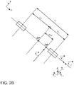
- Figure 2B shows the model on the basis of which the moments that act on the vehicle 1 are determined.
- the vehicle 1 has a vehicle length l from a rear axle to a front axle and a vehicle center of gravity SP .
- the longitudinal axis of the vehicle runs parallel to the x-axis, which corresponds to the direction of travel in the exemplary embodiment.
- the y-axis is defined in the roadway plane perpendicular to it.
- a z-axis is defined as an axis perpendicular to the earth's surface, which in the example runs through the center of gravity SP .
- a pressure point DP is defined as the point at which the wind impinging laterally on the vehicle 1 effectively acts vectorially on the vehicle surface.
- the effect of the wind on the vehicle 1 can be represented as the effect of a force vector that acts on the pressure point DP .
- the position of the pressure point DP can in particular be determined experimentally and depends, for example, on the silhouette of the vehicle 1, aerodynamic surface properties and structures, and on the states of devices which influence the shape of the vehicle 1, for example the opening state of windows.
- the position of the pressure point DP is fixed.
- the method can be adapted to a changed pressure point DP depending on various states of the vehicle 1.
- a distance to the rear axle l H and a distance to the front axle l v are defined from the center of gravity SP , which therefore together give the entire length l of the vehicle 1.
- the lateral component of the air force acting perpendicular to the direction of travel R on the vehicle F L, y corresponds to the air resistance of the vehicle 1 with respect to the lateral component v L, y of the wind perpendicular to the x-axis, i.e. to the vehicle's longitudinal axis.
- e SP the distance between the pressure point DP and the center of gravity SP is shown as e SP designated.
- the wind therefore affects both the vehicle longitudinal dynamics and the vehicle lateral dynamics and is determined in the invention on the basis of the longitudinal and lateral control data of the vehicle that has been detected.
- a transverse, y denotes a transverse chip surface of the vehicle 1, viewed from the direction of the y-axis, C ⁇ H the slip resistance of the rear axle, C ⁇ V the slip resistance of the front axle, c Mz an aerodynamic wind yaw moment coefficient and c y an aerodynamic wind force coefficient.
- inflow angles ⁇ L are used at inflow angles ⁇ L of less than 35 °, preferably less than 25 °, more preferably less than 15 °.
- Measurements with a larger inflow angle ⁇ L can be identified by a filter step and can be excluded from the analysis.
- other methods can be used in these cases, for example c y ( ⁇ L ) being determined in a different way than the linearization.
- F L, y denote the wind side force perpendicular to the longitudinal axis x of the vehicle 1, M L, z the wind yaw moment relative to the z axis or the steering torque, c y the aerodynamic wind side force coefficient and c M, z the aerodynamic wind yaw moment coefficient.
- the component w l, x of the "true" wind parallel to the direction of travel can alternatively be determined on the basis of the vehicle speed and the drive power or the force required for driving, as described below with reference to a further exemplary embodiment.
- the wind direction W L determined as the angle ⁇ L relative to the vehicle 1 can now be transformed into an external, in particular global, coordinate system.
- the pose of the vehicle 1 is used, which is detected by the detection unit 11 as a combination of the position and direction of the vehicle 1 in a global coordinate system.
- the "true" wind speed w L and the wind direction W L can then be output.
- the following vehicle parameters are used to calculate the "true" wind speed w L and the angle ⁇ L of the wind direction W L relative to the vehicle 1, which are typically constant for a vehicle or a vehicle type: the slip resistance of the rear axle C ⁇ H , the slip resistance of the Front axle C ⁇ V , the aerodynamic wind force coefficient c y , the aerodynamic wind yaw moment coefficient c M, z , the transverse cutting surface of the vehicle in the direction of the y-axis A transverse, y , the vehicle length l and the steering ratio i L.
- the density ⁇ L of the air is also taken into account, which can also be assumed to be constant within typical temperature ranges.
- the vehicle speed v F , the steering wheel lock angle ⁇ L and the steering wheel lock torque M L, z are recorded as variables via a CAN bus. These parameters are measured while driving and can change. These are the variables depending on which the "true" wind speed w L and the angle ⁇ L of the wind direction W L relative to the vehicle 1 are determined.
- alternative models can be used to determine the wind speed w L and wind direction W L on the basis of the lateral and longitudinal control data of the vehicle.
- vehicle-specific parameters of vehicle 1 can be replaced by simplifications, for example in order to be able to use the method for a larger number of different vehicle models with little or no changes.
- a current vehicle speed v F - thus also the amount v against the speed of the headwind -, a current steering wheel steering angle ⁇ L and a steering torque M L, z are recorded by means of the detection unit 11.
- the detection takes place via a CAN bus of vehicle 1, via which the necessary data from sensors and devices of vehicle 1 are transmitted.
- the vehicle 1 is driving straight ahead.
- image data of the area in front of the vehicle 1 captured by a video camera are used for this purpose.
- the information about the straight-ahead drive can also be obtained on the basis of a current position of the vehicle 1 and a map.
- the method can also be used when cornering, in which case an initial angle is first determined which corresponds to the steering angle by which the vehicle 1 remains on the road, and this initial position is subtracted from the actual steering wheel turning angle ⁇ L in order to to reach the steering wheel steering angle required for the method.
- the vehicle speed can also be taken into account, in particular in order to compensate for forces on the vehicle that occur during cornering and the resulting kinetic effects such as oversteering or understeering of the vehicle.
- the starting angle is determined taking into account these further kinetic effects when cornering.
- the evaluation unit 12 determines the “true” wind speed w L and the wind direction W L or the angle ⁇ L relative to the vehicle 1.
- external weather data for the position of the vehicle 1 are also received, for example from a weather service. These values can be used to correct the values determined in vehicle 1. Since such weather data are typically determined for greater heights above the ground, a conversion to the height of the vehicle, approximately 0 to 2 m above the ground, can be carried out.
- the detection can take place by means of a driver assistance system, for example an overtaking assistant or a system for supporting driving maneuvers, for example an overtaking process or a follow-up drive, the Relationship of the vehicle 1 to another vehicle is constantly observed and evaluated.
- a driver assistance system for example an overtaking assistant or a system for supporting driving maneuvers, for example an overtaking process or a follow-up drive, the Relationship of the vehicle 1 to another vehicle is constantly observed and evaluated.
- the detection takes place in particular by means of sensors for such a driver assistance system. It is determined to what extent the wind perceived by the vehicle 1 is changed thereby, for example by modeling on the basis of the size of the further vehicle or object. As a result, the determined wind speed w L and flow direction ⁇ L as well as the wind direction W L can be corrected so that the measurement of the vehicle 1 with the reality of the wind matches the real wind as closely as possible. Furthermore, measurements under certain fault conditions can be rejected, for example if the vehicle 1 is in the slipstream of another vehicle. Statistical filtering of the measurements can also take place, for example by discarding suddenly occurring extreme values, or a pattern of changes in the measured values can be recognized and used to reject falsified values.
- the current position of the vehicle 1 is also determined by the detection unit 11, which comprises a position detection unit (not shown). Based on this position and the "true" wind speed w L determined by the evaluation unit 12 and the angle ⁇ L of the wind direction W L relative to the vehicle 1, the evaluation unit 12 generates location-related wind data and transmits it via the interface 13 to the vehicle-external unit 4
- the vehicle-external unit 4 is a server 4 which generates wind map data on the basis of the transmitted location-related wind data.
- the wind map data can also be updated based on the current location-related wind data if old data is already available.
- the wind map data are made available for retrieval by the external server 4.
- the vehicle 1 or another vehicle authorized for this purpose can request and receive wind map data for a specific geographical area. This can be carried out automatically by a device of the vehicle 1, for example by a navigation system that detects that the vehicle is in a specific area or that a planned route runs through the area. On the basis of the information received in this way about the speed and direction of the wind, the energy requirement of the vehicle 1 is determined in order to carry out a journey at a specific speed and along a specific route.
- An operating strategy for vehicle 1, which is geared towards optimum consumption, and an optimized route are determined, and the vehicle is controlled accordingly.
- the method is carried out on the basis of data from a large number of vehicles 1 which are located at different positions and, if appropriate, provide location-related wind data for a common server 4 at different times.
- the data obtained in this way are evaluated in particular by means of "big data” methods, whereby machine learning methods can also be used.
- Wind map data are generated or updated and made available for retrieval.
- a wind forecast for wind conditions is also generated at a later point in time. Methods known per se are also used for this, in particular methods of machine learning.
- information about further weather conditions is also transmitted to the external unit 4 in addition to data about the wind.
- the vehicle 1 can also record moisture or data on the adhesion properties of the road surface, which can be impaired, for example, by the weather conditions, wetness, ice or dirt, are transmitted to the external unit 4.
- Such information can also be included in the location-related wind data and the subsequently generated wind map data.
- a first 31 and a second vehicle 32 move on one plane, while a uniform wind indicated by an arrow 33 blows from a wind direction W L.
- a transverse, x denote the transverse cutting surface of the respective vehicle 31, 32 in the direction of the x-axis and c x the aerodynamic wind force coefficient in the longitudinal direction of the vehicle.
- vehicles 31, 32 of uniform design are assumed, in which all relevant constants are the same.
- the component of the "true" wind speed w L, x along the direction of movement of a vehicle 31, 32 can therefore be determined on the basis of the forces which are necessary to achieve a specific vehicle speed v F. Data on the longitudinal control of the vehicle 31, 32 are therefore recorded in order to record the wind.
- the wind speed w L, x is thus determined parallel to the direction of movement of the vehicle 31, 32. Since the directions of travel differ, different components of the total wind speed w L are determined, in each case in the direction of travel of the vehicle 31, 32, that is to say w L, x, 1 and w L, x, 2 .
- the output data required are determined on the basis of the respective energy consumption of the vehicles 31, 32, which is required to provide the forces for reaching the respective vehicle speeds v F , 1 , v F , 2 .
- the wind direction W L can be determined by performing this method for a plurality of vehicles 31, 32 moving in different directions. If the vehicle 31 runs exactly against the wind direction W L , as shown, the component w L, x , 1 of the wind which counteracts the vehicle speed v F , 1 corresponds exactly to the wind speed:
- a vehicle 32 travels at an angle to the wind direction W L the component w L, x, 2 of the wind which counteracts the vehicle speed v F, 2 is smaller than the wind speed:
- Overall, the component w L, x, 1 , w L, x , 2 of the wind which counteracts the vehicle speed v F , 2 can be calculated as a function of the angle ⁇ L between the wind W L and the direction of travel of the vehicle 31, 32 w L , x , 1 ⁇ L , 1 w L ⁇
- the energy consumption of the vehicles 31, 32 is therefore higher, the more directly they move against the wind direction W L and the more they therefore experience the headwind.
- an approximation method can be carried out using the above-mentioned relationship with a cosine function. This is determined based on the previously determined wind speeds w L, x, 1 , w L, x, 2 against the respective directions of travel, which is the direction of the wind W L and how big the total wind speed w L is. Fitting methods known per se can be used for this.
- a limit value can be provided, about 35 °, preferably 25 °, more preferably 15 °, if a limit is exceeded, a measured value is rejected.
- F R , F st and F B are also recorded in the method. For example, they are determined experimentally and made available in the vehicle. Furthermore, sensors detect the mass m of the vehicles 31, 32, for example using mats for the detection of passengers.
- the rolling coefficient ⁇ R can be known for a vehicle 31, 32 or individual wheels of the vehicles 31, 32 and, if necessary, adapted to the circumstances, for example taking into account tire wear, the current road surface and / or the weather conditions.
- To calculate the gradient resistance F st an gradient ⁇ is recorded when the vehicle 31, 32 is traveling, for example by measuring the inclination of the vehicle 31, 32, the road or using map data.
- the acceleration resistance F B can be determined on the basis of the vehicle mass m and the acceleration a .
- the wind speed can be determined, on which the increase in energy consumption depends.
- the inclination of the road is also recorded, which also determines energy consumption. An energy consumption adjusted for the road inclination can therefore be determined.
- the values recorded in this way are transmitted to the vehicle-external unit 4 and processed as described above, wind data in particular being generated.
- the method steps mentioned, in which the wind direction W L and wind speed w L can be calculated on the basis of different measured variables, are combined in further exemplary embodiments, for example in order to determine the parameters W L , w L of the wind more precisely or to carry out a plausibility check.
- specific information can be used on the basis of the data of an individual vehicle 1 if only a few vehicles 1, 31, 32 are traveling in a geographical area or if the vehicles 1, 31, 32 have only a few different directions of travel R. In this case, it can be difficult to determine the desired values based on the drive power in different directions R.
- To calculate parameters W L , w L of the wind Conversely, this calculation can be carried out particularly accurately or efficiently if data from a large number of vehicles 1, 31, 32 are available which move in different directions R.
Landscapes
- Engineering & Computer Science (AREA)
- Physics & Mathematics (AREA)
- General Physics & Mathematics (AREA)
- Aviation & Aerospace Engineering (AREA)
- Automation & Control Theory (AREA)
- Mathematical Physics (AREA)
- Transportation (AREA)
- Mechanical Engineering (AREA)
- Control Of Driving Devices And Active Controlling Of Vehicle (AREA)
Applications Claiming Priority (1)
| Application Number | Priority Date | Filing Date | Title |
|---|---|---|---|
| DE102018221264.3A DE102018221264B4 (de) | 2018-12-07 | 2018-12-07 | Verfahren und System zum Erfassen eines Windes in einem geografischen Bereich |
Publications (1)
| Publication Number | Publication Date |
|---|---|
| EP3663771A1 true EP3663771A1 (fr) | 2020-06-10 |
Family
ID=68696244
Family Applications (1)
| Application Number | Title | Priority Date | Filing Date |
|---|---|---|---|
| EP19211353.8A Withdrawn EP3663771A1 (fr) | 2018-12-07 | 2019-11-25 | Procédé et système de détection d'un vent dans une zone géographique |
Country Status (2)
| Country | Link |
|---|---|
| EP (1) | EP3663771A1 (fr) |
| DE (1) | DE102018221264B4 (fr) |
Cited By (2)
| Publication number | Priority date | Publication date | Assignee | Title |
|---|---|---|---|---|
| US12509120B2 (en) * | 2022-04-25 | 2025-12-30 | Rakuten Group, Inc. | Unmanned vehicle and delivery system |
| CN121232318A (zh) * | 2025-11-28 | 2025-12-30 | 青岛镭测创芯科技有限公司 | 一种应用于流动车辆的气象参数测量方法和系统 |
Families Citing this family (4)
| Publication number | Priority date | Publication date | Assignee | Title |
|---|---|---|---|---|
| DE102021203484B3 (de) | 2021-04-08 | 2022-09-22 | Volkswagen Aktiengesellschaft | Verfahren zum Erstellen einer Führungstrajektorie für ein erstes Kraftfahrzeug, Verfahren zum Steuern eines Kraftfahrzeugs sowie Verfahren zum Betreiben eines Kraftfahrzeugs |
| DE102022002172A1 (de) | 2022-06-15 | 2023-12-21 | Mercedes-Benz Group AG | Verfahren zur energieoptimierten Vorgabe einer Fahrgeschwindigkeit |
| DE102023200465A1 (de) * | 2023-01-23 | 2024-07-25 | Volkswagen Aktiengesellschaft | Winderkennungsvorrichtung und Verfahren zum vorausschauenden Erkennen von Windeinflüssen auf ein Egofahrzeug |
| DE102023002579B3 (de) | 2023-06-26 | 2024-07-25 | Mercedes-Benz Group AG | Verfahren zum Betreiben eines Fahrzeugs mit Vorder- und Hinterachslenkung und Fahrzeug |
Citations (12)
| Publication number | Priority date | Publication date | Assignee | Title |
|---|---|---|---|---|
| DE10162335A1 (de) | 2001-12-18 | 2003-07-10 | Zf Lemfoerder Metallwaren Ag | Verfahren und Vorrichtung zur Erzeugung und Aktualisierung einer Wege- und/oder Wegezustandskarte |
| DE102004017638A1 (de) * | 2004-04-10 | 2005-10-27 | Daimlerchrysler Ag | Vorrichtung und ein Verfahren für ein Fahrzeug zur Ermittlung mindestens eines Seitenwind-Wertes |
| DE102010029245A1 (de) * | 2010-05-25 | 2011-12-01 | Robert Bosch Gmbh | Verfahren zur Seitenwindkompensation in Fahrzeugen |
| DE102010039569A1 (de) | 2010-08-20 | 2012-02-23 | Robert Bosch Gmbh | Verfahren und Vorrichtung zum Ermitteln einer Energieaufwandsinformation für eine Fahrt eines Landfahrzeugs |
| US20120310536A1 (en) | 2010-03-31 | 2012-12-06 | Honda Motor Co., Ltd. | Weather information processing device and weather information processing system |
| EP2591967A2 (fr) | 2011-11-11 | 2013-05-15 | Volkswagen Aktiengesellschaft | Procédé de fonctionnement d'un véhicule, dispositif de commande et véhicule |
| US20130319096A1 (en) * | 2012-05-30 | 2013-12-05 | Robert Bosch Gmbh | Method for determining headwind velocity |
| DE102012220406A1 (de) | 2012-11-09 | 2014-05-28 | Robert Bosch Gmbh | Verfahren zur Ermittlung der Geschwindigkeit eines Fahrtwindes und einer Windgeschwindigkeit |
| JP2017210171A (ja) * | 2016-05-27 | 2017-11-30 | 日立オートモティブシステムズ株式会社 | 車両制御装置 |
| DE102016209678A1 (de) | 2016-06-02 | 2017-12-07 | Ford Global Technologies, Llc | Verfahren zum Betreiben eines Kraftfahrzeugs, Kraftfahrzeug und System zum Verarbeiten von Daten zu auf ein Kraftfahrzeug einwirkenden Seitenwindlasten |
| DE102016223299A1 (de) | 2016-11-24 | 2018-05-24 | Robert Bosch Gmbh | Verfahren zum Betreiben eines Kraftfahrzeugs |
| DE102017206320A1 (de) * | 2017-04-12 | 2018-10-18 | Audi Ag | Verfahren zum Ermitteln einer Geschwindigkeit von Wind |
Family Cites Families (1)
| Publication number | Priority date | Publication date | Assignee | Title |
|---|---|---|---|---|
| DE102014213504B3 (de) * | 2014-07-11 | 2015-10-15 | Robert Bosch Gmbh | Motorisch und/oder mit Muskelkraft betreibbares Fahrzeug |
-
2018
- 2018-12-07 DE DE102018221264.3A patent/DE102018221264B4/de active Active
-
2019
- 2019-11-25 EP EP19211353.8A patent/EP3663771A1/fr not_active Withdrawn
Patent Citations (12)
| Publication number | Priority date | Publication date | Assignee | Title |
|---|---|---|---|---|
| DE10162335A1 (de) | 2001-12-18 | 2003-07-10 | Zf Lemfoerder Metallwaren Ag | Verfahren und Vorrichtung zur Erzeugung und Aktualisierung einer Wege- und/oder Wegezustandskarte |
| DE102004017638A1 (de) * | 2004-04-10 | 2005-10-27 | Daimlerchrysler Ag | Vorrichtung und ein Verfahren für ein Fahrzeug zur Ermittlung mindestens eines Seitenwind-Wertes |
| US20120310536A1 (en) | 2010-03-31 | 2012-12-06 | Honda Motor Co., Ltd. | Weather information processing device and weather information processing system |
| DE102010029245A1 (de) * | 2010-05-25 | 2011-12-01 | Robert Bosch Gmbh | Verfahren zur Seitenwindkompensation in Fahrzeugen |
| DE102010039569A1 (de) | 2010-08-20 | 2012-02-23 | Robert Bosch Gmbh | Verfahren und Vorrichtung zum Ermitteln einer Energieaufwandsinformation für eine Fahrt eines Landfahrzeugs |
| EP2591967A2 (fr) | 2011-11-11 | 2013-05-15 | Volkswagen Aktiengesellschaft | Procédé de fonctionnement d'un véhicule, dispositif de commande et véhicule |
| US20130319096A1 (en) * | 2012-05-30 | 2013-12-05 | Robert Bosch Gmbh | Method for determining headwind velocity |
| DE102012220406A1 (de) | 2012-11-09 | 2014-05-28 | Robert Bosch Gmbh | Verfahren zur Ermittlung der Geschwindigkeit eines Fahrtwindes und einer Windgeschwindigkeit |
| JP2017210171A (ja) * | 2016-05-27 | 2017-11-30 | 日立オートモティブシステムズ株式会社 | 車両制御装置 |
| DE102016209678A1 (de) | 2016-06-02 | 2017-12-07 | Ford Global Technologies, Llc | Verfahren zum Betreiben eines Kraftfahrzeugs, Kraftfahrzeug und System zum Verarbeiten von Daten zu auf ein Kraftfahrzeug einwirkenden Seitenwindlasten |
| DE102016223299A1 (de) | 2016-11-24 | 2018-05-24 | Robert Bosch Gmbh | Verfahren zum Betreiben eines Kraftfahrzeugs |
| DE102017206320A1 (de) * | 2017-04-12 | 2018-10-18 | Audi Ag | Verfahren zum Ermitteln einer Geschwindigkeit von Wind |
Non-Patent Citations (1)
| Title |
|---|
| MANFRED MITSCHKE ET AL: "Dynamik der Kraftfahrzeuge - Seitenwindverhalten", 12 January 2015 (2015-01-12), Wiesbaden, pages 696 - 712, XP055687294, ISBN: 978-3-658-05068-9, Retrieved from the Internet <URL:https://ebookcentral.proquest.com/lib/epo-ebooks/detail.action?docID=1965817> [retrieved on 20200420] * |
Cited By (2)
| Publication number | Priority date | Publication date | Assignee | Title |
|---|---|---|---|---|
| US12509120B2 (en) * | 2022-04-25 | 2025-12-30 | Rakuten Group, Inc. | Unmanned vehicle and delivery system |
| CN121232318A (zh) * | 2025-11-28 | 2025-12-30 | 青岛镭测创芯科技有限公司 | 一种应用于流动车辆的气象参数测量方法和系统 |
Also Published As
| Publication number | Publication date |
|---|---|
| DE102018221264B4 (de) | 2021-03-18 |
| DE102018221264A1 (de) | 2020-06-10 |
Similar Documents
| Publication | Publication Date | Title |
|---|---|---|
| DE102018221265B4 (de) | Verfahren und System zum Erfassen eines auf ein Fahrzeug einwirkenden Windes | |
| DE102018221264B4 (de) | Verfahren und System zum Erfassen eines Windes in einem geografischen Bereich | |
| DE102018118220B4 (de) | Verfahren zur Schätzung der Lokalisierungsgüte bei der Eigenlokalisierung eines Fahrzeuges, Vorrichtung für die Durchführung von Verfahrensschritten des Verfahrens, Fahrzeug sowie Computerprogramm | |
| DE102013200132B4 (de) | Fahrspurhaltesystem für ein Fahrzeug | |
| DE112012007157B4 (de) | Fahrunterstützungsvorrichtung und Fahrunterstützungsverfahren | |
| DE112018008222T5 (de) | Bewegungsplan-erzeugungseinrichtung und autonomes fahrsystem | |
| DE112019006548T5 (de) | Lenkwinkelkalibrierung | |
| DE102018219665B4 (de) | Steuereinheit zum Betreiben eines autonomen Fahrzeugs | |
| DE102019103352A1 (de) | Trajektorienverfolgung für die fahrzeugseitensteuerung unter verwendung eines neuronalen netzwerks | |
| DE102019133708A1 (de) | Verfahren und vorrichtung zum erfassen von statischen und dynamischen informationen auf spurniveau | |
| EP3695233B1 (fr) | Procédé et système permettant de déterminer des vitesses de vent effectives pour des véhicules à moteur | |
| DE102019214628A1 (de) | Validierung von Umfelderfassung mittels Satelitenbildern und SAR-Radardaten | |
| DE102021110868B4 (de) | Fahrzeugsteuerungssysteme und -verfahren | |
| DE102020102717A1 (de) | Verfahren und systeme zur steuerung der seitlichen position des fahrzeugs über eine kreuzung | |
| DE102018101691A1 (de) | Invasive aktive dynamische Tests zur Bestimmung des Oberflächen-Reibungskoeffizienten | |
| DE102017115752A1 (de) | Fahrzeug und Verfahren zum Steuern desselbigen | |
| DE102012212740A1 (de) | System und Verfahren zum Aktualisieren einer digitalen Karte eines Fahrerassistenzsystems | |
| DE102021214193A1 (de) | Fahrzeug und verfahren zur steuerung der reaktion auf einfädeln | |
| DE102020133160B4 (de) | Dynamische Geschwindigkeitsplanungsmethode für autonomes Fahrzeug und entsprechendes System | |
| DE102017129501A1 (de) | Autonome Kraftfahrzeug-Objekterkennung | |
| DE102016012465A1 (de) | Verfahren zur Bestimmung einer Änderung im auf ein Kraftfahrzeug wirkenden Luftwiderstand | |
| EP4303103A1 (fr) | Système de spoilers réglables pour un véhicule automobile et véhicule automobile équipé d'un tel système de spoilers | |
| DE102022211064A1 (de) | Fahrzeugfahrsteuerungsverarbeitungssystem | |
| DE102019132150A1 (de) | Verfahren zum automatischen Kalibrieren eines Umfeldsensors, insbesondere eines Lidar-Sensors, eines Fahrzeugs auf Grundlage von Belegungskarten sowie Recheneinrichtung | |
| DE102019131667A1 (de) | Fahrzeug und verfahren zur voraussage einer kollision |
Legal Events
| Date | Code | Title | Description |
|---|---|---|---|
| PUAI | Public reference made under article 153(3) epc to a published international application that has entered the european phase |
Free format text: ORIGINAL CODE: 0009012 |
|
| STAA | Information on the status of an ep patent application or granted ep patent |
Free format text: STATUS: THE APPLICATION HAS BEEN PUBLISHED |
|
| AK | Designated contracting states |
Kind code of ref document: A1 Designated state(s): AL AT BE BG CH CY CZ DE DK EE ES FI FR GB GR HR HU IE IS IT LI LT LU LV MC MK MT NL NO PL PT RO RS SE SI SK SM TR |
|
| AX | Request for extension of the european patent |
Extension state: BA ME |
|
| STAA | Information on the status of an ep patent application or granted ep patent |
Free format text: STATUS: REQUEST FOR EXAMINATION WAS MADE |
|
| 17P | Request for examination filed |
Effective date: 20201210 |
|
| RBV | Designated contracting states (corrected) |
Designated state(s): AL AT BE BG CH CY CZ DE DK EE ES FI FR GB GR HR HU IE IS IT LI LT LU LV MC MK MT NL NO PL PT RO RS SE SI SK SM TR |
|
| STAA | Information on the status of an ep patent application or granted ep patent |
Free format text: STATUS: EXAMINATION IS IN PROGRESS |
|
| 17Q | First examination report despatched |
Effective date: 20211123 |
|
| STAA | Information on the status of an ep patent application or granted ep patent |
Free format text: STATUS: THE APPLICATION IS DEEMED TO BE WITHDRAWN |
|
| 18D | Application deemed to be withdrawn |
Effective date: 20230307 |