EP3663731A1 - Acoustic air data sensor and system - Google Patents
Acoustic air data sensor and system Download PDFInfo
- Publication number
- EP3663731A1 EP3663731A1 EP19214174.5A EP19214174A EP3663731A1 EP 3663731 A1 EP3663731 A1 EP 3663731A1 EP 19214174 A EP19214174 A EP 19214174A EP 3663731 A1 EP3663731 A1 EP 3663731A1
- Authority
- EP
- European Patent Office
- Prior art keywords
- acoustic
- air data
- air
- sound
- speed
- Prior art date
- Legal status (The legal status is an assumption and is not a legal conclusion. Google has not performed a legal analysis and makes no representation as to the accuracy of the status listed.)
- Granted
Links
Images


Classifications
-
- G—PHYSICS
- G01—MEASURING; TESTING
- G01H—MEASUREMENT OF MECHANICAL VIBRATIONS OR ULTRASONIC, SONIC OR INFRASONIC WAVES
- G01H5/00—Measuring propagation velocity of ultrasonic, sonic or infrasonic waves, e.g. of pressure waves
-
- G—PHYSICS
- G01—MEASURING; TESTING
- G01D—MEASURING NOT SPECIALLY ADAPTED FOR A SPECIFIC VARIABLE; ARRANGEMENTS FOR MEASURING TWO OR MORE VARIABLES NOT COVERED IN A SINGLE OTHER SUBCLASS; TARIFF METERING APPARATUS; MEASURING OR TESTING NOT OTHERWISE PROVIDED FOR
- G01D21/00—Measuring or testing not otherwise provided for
- G01D21/02—Measuring two or more variables by means not covered by a single other subclass
-
- G—PHYSICS
- G01—MEASURING; TESTING
- G01P—MEASURING LINEAR OR ANGULAR SPEED, ACCELERATION, DECELERATION, OR SHOCK; INDICATING PRESENCE, ABSENCE, OR DIRECTION, OF MOVEMENT
- G01P13/00—Indicating or recording presence, absence, or direction, of movement
- G01P13/02—Indicating direction only, e.g. by weather vane
- G01P13/025—Indicating direction only, e.g. by weather vane indicating air data, i.e. flight variables of an aircraft, e.g. angle of attack, side slip, shear, yaw
-
- B—PERFORMING OPERATIONS; TRANSPORTING
- B64—AIRCRAFT; AVIATION; COSMONAUTICS
- B64D—EQUIPMENT FOR FITTING IN OR TO AIRCRAFT; FLIGHT SUITS; PARACHUTES; ARRANGEMENT OR MOUNTING OF POWER PLANTS OR PROPULSION TRANSMISSIONS IN AIRCRAFT
- B64D43/00—Arrangements or adaptations of instruments
- B64D43/02—Arrangements or adaptations of instruments for indicating aircraft speed or stalling conditions
-
- G—PHYSICS
- G01—MEASURING; TESTING
- G01K—MEASURING TEMPERATURE; MEASURING QUANTITY OF HEAT; THERMALLY-SENSITIVE ELEMENTS NOT OTHERWISE PROVIDED FOR
- G01K11/00—Measuring temperature based upon physical or chemical changes not covered by groups G01K3/00, G01K5/00, G01K7/00 or G01K9/00
- G01K11/22—Measuring temperature based upon physical or chemical changes not covered by groups G01K3/00, G01K5/00, G01K7/00 or G01K9/00 using measurement of acoustic effects
- G01K11/24—Measuring temperature based upon physical or chemical changes not covered by groups G01K3/00, G01K5/00, G01K7/00 or G01K9/00 using measurement of acoustic effects of the velocity of propagation of sound
-
- G—PHYSICS
- G01—MEASURING; TESTING
- G01P—MEASURING LINEAR OR ANGULAR SPEED, ACCELERATION, DECELERATION, OR SHOCK; INDICATING PRESENCE, ABSENCE, OR DIRECTION, OF MOVEMENT
- G01P5/00—Measuring speed of fluids, e.g. of air stream; Measuring speed of bodies relative to fluids, e.g. of ship, of aircraft
- G01P5/14—Measuring speed of fluids, e.g. of air stream; Measuring speed of bodies relative to fluids, e.g. of ship, of aircraft by measuring differences of pressure in the fluid
- G01P5/16—Measuring speed of fluids, e.g. of air stream; Measuring speed of bodies relative to fluids, e.g. of ship, of aircraft by measuring differences of pressure in the fluid using Pitot tubes, e.g. Machmeter
- G01P5/165—Arrangements or constructions of Pitot tubes
-
- G—PHYSICS
- G01—MEASURING; TESTING
- G01P—MEASURING LINEAR OR ANGULAR SPEED, ACCELERATION, DECELERATION, OR SHOCK; INDICATING PRESENCE, ABSENCE, OR DIRECTION, OF MOVEMENT
- G01P5/00—Measuring speed of fluids, e.g. of air stream; Measuring speed of bodies relative to fluids, e.g. of ship, of aircraft
- G01P5/24—Measuring speed of fluids, e.g. of air stream; Measuring speed of bodies relative to fluids, e.g. of ship, of aircraft by measuring the direct influence of the streaming fluid on the properties of a detecting acoustical wave
- G01P5/245—Measuring speed of fluids, e.g. of air stream; Measuring speed of bodies relative to fluids, e.g. of ship, of aircraft by measuring the direct influence of the streaming fluid on the properties of a detecting acoustical wave by measuring transit time of acoustical waves
Definitions
- This disclosure relates generally to acoustic air data sensors, and more particularly to acoustic air data sensors that measure a speed of sound in air.
- Modern aircraft often incorporate air data systems that calculate air data outputs based on measured parameters collected from various sensors positioned about the aircraft. For instance, many air data systems utilize air data probes that measure parameters of oncoming airflow about the aircraft exterior to generate aircraft air data outputs, such as angle of attack (i.e., an angle between the oncoming airflow or relative wind and a reference line of the aircraft, such as a chord of a wing of the aircraft), calibrated airspeed, Mach number, altitude, or other air data parameters.
- angle of attack i.e., an angle between the oncoming airflow or relative wind and a reference line of the aircraft, such as a chord of a wing of the aircraft
- calibrated airspeed Mach number
- Mach number altitude
- altitude altitude
- the speed of sound is inferentially determined based on measured parameters, such as a total air temperature of the exterior air. Such inferential determinations of the speed of sound, however, can result in lower accuracy of the air data parameter outputs.
- an acoustic air data sensor for an aircraft includes an acoustic transmitter, an acoustic receiver, an acoustic signal generator, timing circuitry, speed of sound determination circuitry, and communication circuitry.
- the acoustic transmitter is located to transmit an acoustic signal through an airflow stagnation chamber that is pneumatically connected to an exterior of the aircraft and configured to receive and stagnate airflow from the exterior of the aircraft.
- the acoustic receiver is positioned at a distance from the acoustic transmitter to receive the acoustic signal transmitted by the acoustic transmitter through the airflow stagnation chamber.
- the acoustic signal generator causes the acoustic transmitter to provide the acoustic signal.
- the timing circuitry determines a time of flight of the acoustic signal from the acoustic transmitter to the acoustic receiver.
- the speed of sound determination circuitry determines, based on the time of flight and the distance, a speed of sound through air in the stagnation chamber.
- the communication circuitry outputs the speed of sound.
- an air data system for an aircraft includes an acoustic air data sensor, an air data sensor, and an air data computer.
- the acoustic air data sensor includes an acoustic transmitter, an acoustic receiver, an acoustic signal generator, timing circuitry, speed of sound determination circuitry, and communication circuitry.
- the acoustic transmitter is located to transmit an acoustic signal through an airflow stagnation chamber that is pneumatically connected to an exterior of the aircraft and configured to receive and stagnate airflow from the exterior of the aircraft.
- the acoustic receiver is positioned at a distance from the acoustic transmitter to receive the acoustic signal transmitted by the acoustic transmitter through the airflow stagnation chamber.
- the air data computer is configured to receive the speed of sound from the acoustic air data sensor, receive the air data measurements from the air data sensor, and determine one or more air data output parameters using the received speed of sound from the acoustic air data sensor and the received air data measurements from the air data sensor.
- an air data system includes an acoustic air data sensor that measures the speed of sound through air within an airflow stagnation chamber that is pneumatically connected to an exterior of the aircraft. That is, rather than measure parameters related to the speed of sound and inferentially determining the speed of sound for use with air data output calculations, the air data system described herein directly measures the speed of sound through air about the exterior of the aircraft, thereby increasing accuracy of the speed of sound determinations and providing direct measurement results for use with, e.g., air data parameter calculations and/or system calibration and configuration operations.
- the acoustic air data sensor includes an acoustic transmitter and an acoustic receiver.
- the acoustic transmitter provides an acoustic signal through the stagnation chamber, which is received by the acoustic receiver.
- Air within the stagnation chamber has, via the pneumatic connection to the aircraft exterior, similar properties to the exterior air, such as with respect to temperature and relative humidity.
- Stagnated air i.e., substantially unmoving air
- the acoustic air data sensor described herein determines the speed of sound through the air in the stagnation chamber (and hence through the pneumatically-connected air about the aircraft exterior) based on a time of flight of the acoustic signal from the acoustic transmitter to the acoustic receiver, such as by dividing a known distance between the acoustic transmitter and the acoustic receiver by the determined time of flight of the acoustic signal.
- the acoustic air data sensor utilizes the determined speed of sound to produce a temperature measurement of the air within the stagnation chamber.
- the speed of sound and/or air temperature measurements are output to, e.g., an air data computer that utilizes one or more of the measurements for air data output parameter calculations and/or system configuration and calibration operations.
- FIG. 1 is a schematic diagram of one example of air data system 10 of aircraft 12 including acoustic air data sensor 14 that outputs a speed of sound measurement C 0 , air data computer 16, and acoustic anemometer 18. That is, in the example of FIG. 1 , air data system 10 utilizes speed of sound measurement C 0 received from acoustic air data sensor 14 for air data operations associated with acoustic measurements received from acoustic anemometer 18. In other examples, such as the example of FIG.
- the acoustic signal transmitted by acoustic transmitter 20 and received by acoustic receiver 22 can take the form of an acoustic pulse, and oscillating acoustic signal, a broadband acoustic signal, a random source acoustic signal, or other form of acoustic signal.
- acoustic transmitter 20 and acoustic receiver 22 are illustrated as located within stagnation chamber 36, in other examples, any one or more of acoustic transmitter 20 and acoustic receiver 22 can be located outside of stagnation chamber 36, such as adjacent a wall of stagnation chamber 36 to transmit and/or receive the acoustic signal.
- Stagnation chamber 36 in the example of FIG. 1 , is located within an interior of aircraft 12 and is pneumatically connected to an airflow about an exterior of aircraft 12 via inlet 38 and outlet 40. In operation, air passes over the exterior of aircraft 12 in direction A during, e.g., forward flight of aircraft 12. A portion of the airflow over the exterior of aircraft 12 is directed to stagnation chamber 36 through inlet 38.
- Stagnation chamber 36 in the example of FIG. 1 , is a chamber formed within the interior of aircraft 12 (i.e., under the aircraft skin) and configured to stagnate airflow received via inlet 38 and exiting via outlet 40.
- Stagnation chamber 36 can therefore be configured to cause stagnation of air within chamber 36, such that a velocity of airflow in a direction from acoustic transmitter 20 to acoustic receiver 22 is less than, e.g., two percent of a velocity of airflow about the exterior of aircraft 12.
- stagnation chamber 36 is illustrated and described herein as a chamber formed within an interior of aircraft 12, it should be understood that aspects of this disclosure are not so limited.
- stagnation chamber 36 can be located within and/or can be considered a portion of an existing area of stagnation (i.e., low airflow) of aircraft 12, such as within existing cavities of aircraft 12 (e.g., a wheel well, under wing flaps, or other cavities), locations of separated wakes of aircraft 12, or other locations of aircraft 12 having low flow velocity (e.g., less than two percent of a velocity of airflow about the exterior of aircraft 12).
- speed of sound determination circuitry 32 determines the speed of sound based on a mean, a median, a mode, or other central tendency of a plurality of speed of sound determinations.
- timing circuitry 30 can cause acoustic signal generator circuitry 28 to transmit a plurality of acoustic signals at a plurality of times, such as at a frequency of 0.1 Hertz (Hz), 0.5 Hz, 1 Hz, 5 Hz, or other regular or irregular frequencies.
- Timing circuitry 30 can provide an indication of the time of flight of each of the plurality of acoustic signals to speed of sound determination circuitry 32.
- Speed of sound determination circuitry 32 can determine the speed of sound for each of the plurality of acoustic signals, and can determine the speed of sound through air in the stagnation chamber (and hence through air around the exterior of the aircraft via the pneumatic connection to the exterior air) based on a central tendency of the plurality of speed of sound determinations.
- acoustic air data sensor controller 24 can include one or more processors and computer-readable memory encoded with instructions that, when executed by the one or more processors, cause acoustic air data sensor controller 24 to operate in accordance with techniques described herein.
- acoustic anemometer 18 can be an acoustic angle-of-attack sensor as described in currently co-pending application 15/934,584 , entitled “ACOUSTIC ANGLE-OF-ATTACK SENSOR,” filed on March 23, 2018.
- the plurality of acoustic receivers of acoustic anemometer 18 receive, at varying times, the acoustic pulse emitted by the acoustic transmitter of acoustic anemometer 18.
- the time delay between transmission of the acoustic pulse by the acoustic transmitter and reception by the plurality of acoustic receivers is dependent upon the velocity of exterior airflow over acoustic anemometer 18, the angle of attack of the local exterior airflow, and the speed of sound through the local exterior air.
- air data computer 16 utilizes speed of sound measurement C 0 received from acoustic air data sensor controller 24 for calibration and/or configuration operations associated with measurements received from acoustic anemometer 18. For instance, because acoustic propagation of sound waves traveling between the acoustic transmitter of acoustic anemometer 18 and the acoustic receivers of acoustic anemometer 18 is impacted by flow-induced effects of the airflow about the exterior of aircraft 12, air data computer 16 can utilize the speed of sound measurement C 0 received from acoustic air data sensor controller 24 for calibration and/or configuration operations associated with acoustic anemometer 18, rather than determine a speed of sound through the external air using the time-of-flight of acoustic pulses between the acoustic transmitter of acoustic anemometer 18 and the acoustic receivers of acoustic anemometer 18.
- airflow over acoustic anemometer 18 has velocity V at angle of attack ⁇ .
- the time-of-flight ( ⁇ ) of an acoustic pulse emitted by acoustic transmitter 46 can be measured to each of acoustic receivers 48A-48L.
- air data computer 16 can utilize time-of-flight information received from acoustic anemometer 18 and speed of sound measurement C 0 received from acoustic air data sensor 14 to determine air data parameter outputs.
- a correction and/or calibration can be applied to speed of sound measurement C 0 received from acoustic air data sensor 14 to correlate the speed of sound measurement C 0 within stagnation chamber 36 with the speed of sound of the external airflow across acoustic anemometer 18.
- T MC 0 2 ⁇ R
- T the total air temperature (TAT) of the air in the stagnation chamber
- M the molecular mass of the air within stagnation chamber 36
- C 0 the speed of sound measurement received from speed of sound determination circuitry 32
- y the adiabatic constant of the air within stagnation chamber 36
- R the universal gas constant (8.314 J/mol K).
- An acoustic air data sensor for an aircraft includes an acoustic transmitter, an acoustic receiver, an acoustic signal generator, timing circuitry, speed of sound determination circuitry, and communication circuitry.
- the acoustic transmitter is located to transmit an acoustic signal through an airflow stagnation chamber that is pneumatically connected to an exterior of the aircraft and configured to receive and stagnate airflow from the exterior of the aircraft.
- the acoustic receiver is positioned at a distance from the acoustic transmitter to receive the acoustic signal transmitted by the acoustic transmitter through the airflow stagnation chamber.
- the acoustic signal generator causes the acoustic transmitter to provide the acoustic signal.
Landscapes
- Physics & Mathematics (AREA)
- Engineering & Computer Science (AREA)
- General Physics & Mathematics (AREA)
- Aviation & Aerospace Engineering (AREA)
- Acoustics & Sound (AREA)
- Multimedia (AREA)
- Measuring Temperature Or Quantity Of Heat (AREA)
Abstract
Description
- This disclosure relates generally to acoustic air data sensors, and more particularly to acoustic air data sensors that measure a speed of sound in air.
- Modern aircraft often incorporate air data systems that calculate air data outputs based on measured parameters collected from various sensors positioned about the aircraft. For instance, many air data systems utilize air data probes that measure parameters of oncoming airflow about the aircraft exterior to generate aircraft air data outputs, such as angle of attack (i.e., an angle between the oncoming airflow or relative wind and a reference line of the aircraft, such as a chord of a wing of the aircraft), calibrated airspeed, Mach number, altitude, or other air data parameters.
- Many of the calculated air data outputs vary as a function of the speed of sound through the air about the aircraft exterior. Often, the speed of sound is inferentially determined based on measured parameters, such as a total air temperature of the exterior air. Such inferential determinations of the speed of sound, however, can result in lower accuracy of the air data parameter outputs.
- In one aspect of the present invention, an acoustic air data sensor for an aircraft includes an acoustic transmitter, an acoustic receiver, an acoustic signal generator, timing circuitry, speed of sound determination circuitry, and communication circuitry. The acoustic transmitter is located to transmit an acoustic signal through an airflow stagnation chamber that is pneumatically connected to an exterior of the aircraft and configured to receive and stagnate airflow from the exterior of the aircraft. The acoustic receiver is positioned at a distance from the acoustic transmitter to receive the acoustic signal transmitted by the acoustic transmitter through the airflow stagnation chamber. The acoustic signal generator causes the acoustic transmitter to provide the acoustic signal. The timing circuitry determines a time of flight of the acoustic signal from the acoustic transmitter to the acoustic receiver. The speed of sound determination circuitry determines, based on the time of flight and the distance, a speed of sound through air in the stagnation chamber. The communication circuitry outputs the speed of sound.
- In another aspect of the present invention, an air data system for an aircraft includes an acoustic air data sensor, an air data sensor, and an air data computer. The acoustic air data sensor includes an acoustic transmitter, an acoustic receiver, an acoustic signal generator, timing circuitry, speed of sound determination circuitry, and communication circuitry. The acoustic transmitter is located to transmit an acoustic signal through an airflow stagnation chamber that is pneumatically connected to an exterior of the aircraft and configured to receive and stagnate airflow from the exterior of the aircraft. The acoustic receiver is positioned at a distance from the acoustic transmitter to receive the acoustic signal transmitted by the acoustic transmitter through the airflow stagnation chamber. The acoustic signal generator causes the acoustic transmitter to provide the acoustic signal. The timing circuitry determines a time of flight of the acoustic signal from the acoustic transmitter to the acoustic receiver. The speed of sound determination circuitry determines, based on the time of flight and the distance, a speed of sound through air in the stagnation chamber. The communication circuitry outputs the speed of sound. The air data sensor is mounted to the exterior of the aircraft and produces air data measurements. The air data computer is configured to receive the speed of sound from the acoustic air data sensor, receive the air data measurements from the air data sensor, and determine one or more air data output parameters using the received speed of sound from the acoustic air data sensor and the received air data measurements from the air data sensor.
-
-
FIG. 1 is a schematic diagram of one example of an aircraft air data system that includes an air data computer, an acoustic anemometer, and an acoustic air data sensor that outputs a speed of sound measurement. -
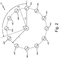
FIG. 2 is a top-down view of the acoustic anemometer ofFIG. 1 . -
FIG. 3 is a schematic diagram of another example of the aircraft air data system ofFIG. 1 including an acoustic air data sensor that outputs an air temperature measurement. - According to techniques of this disclosure, an air data system includes an acoustic air data sensor that measures the speed of sound through air within an airflow stagnation chamber that is pneumatically connected to an exterior of the aircraft. That is, rather than measure parameters related to the speed of sound and inferentially determining the speed of sound for use with air data output calculations, the air data system described herein directly measures the speed of sound through air about the exterior of the aircraft, thereby increasing accuracy of the speed of sound determinations and providing direct measurement results for use with, e.g., air data parameter calculations and/or system calibration and configuration operations.
- As described herein, airflow about the aircraft exterior is directed to the stagnation chamber, which is configured to receive and stagnate the airflow. The acoustic air data sensor includes an acoustic transmitter and an acoustic receiver. The acoustic transmitter provides an acoustic signal through the stagnation chamber, which is received by the acoustic receiver. Air within the stagnation chamber has, via the pneumatic connection to the aircraft exterior, similar properties to the exterior air, such as with respect to temperature and relative humidity. Stagnated air (i.e., substantially unmoving air) within the stagnation chamber, however, does not impart directional airflow effects that could impact the acoustic signal as it travels between the acoustic transmitter and the acoustic receiver.
- The acoustic air data sensor described herein determines the speed of sound through the air in the stagnation chamber (and hence through the pneumatically-connected air about the aircraft exterior) based on a time of flight of the acoustic signal from the acoustic transmitter to the acoustic receiver, such as by dividing a known distance between the acoustic transmitter and the acoustic receiver by the determined time of flight of the acoustic signal. In some examples, the acoustic air data sensor utilizes the determined speed of sound to produce a temperature measurement of the air within the stagnation chamber. The speed of sound and/or air temperature measurements are output to, e.g., an air data computer that utilizes one or more of the measurements for air data output parameter calculations and/or system configuration and calibration operations.
-
FIG. 1 is a schematic diagram of one example ofair data system 10 ofaircraft 12 including acousticair data sensor 14 that outputs a speed of sound measurement C0,air data computer 16, andacoustic anemometer 18. That is, in the example ofFIG. 1 ,air data system 10 utilizes speed of sound measurement C0 received from acousticair data sensor 14 for air data operations associated with acoustic measurements received fromacoustic anemometer 18. In other examples, such as the example ofFIG. 3 ,air data system 10 utilizes one or more of speed of sound measurement C0 and an air temperature (T) measurement received from acousticair data sensor 14 for air data operations associated with measurements received from, e.g., a pressure-based or other air data sensor, as is further described below. In yet other examples,air data system 10 utilizes both speed of sound measurement C0 and the temperature measurement received from acousticair data sensor 14 for air data operations associated with measurements received from bothacoustic anemometer 18 and a pressure-based or other air data sensor mounted to an exterior ofaircraft 12. - As illustrated in
FIG. 1 , acousticair data sensor 14 includesacoustic transmitter 20,acoustic receiver 22, and acoustic airdata sensor controller 24. Acoustic airdata sensor controller 24 includesreceiver circuitry 26, acousticsignal generator circuitry 28,timing circuitry 30, speed ofsound determination circuitry 32, andcommunication circuitry 34.Acoustic transmitter 20 is located to transmit an acoustic signal throughstagnation chamber 36.Acoustic receiver 22 is located at a known distance D fromacoustic transmitter 22 to receive the acoustic signal after transmission through distance D ofstagnation chamber 36. The acoustic signal transmitted byacoustic transmitter 20 and received byacoustic receiver 22 can take the form of an acoustic pulse, and oscillating acoustic signal, a broadband acoustic signal, a random source acoustic signal, or other form of acoustic signal. Though in the example ofFIG. 1 ,acoustic transmitter 20 andacoustic receiver 22 are illustrated as located withinstagnation chamber 36, in other examples, any one or more ofacoustic transmitter 20 andacoustic receiver 22 can be located outside ofstagnation chamber 36, such as adjacent a wall ofstagnation chamber 36 to transmit and/or receive the acoustic signal. -
Stagnation chamber 36, in the example ofFIG. 1 , is located within an interior ofaircraft 12 and is pneumatically connected to an airflow about an exterior ofaircraft 12 viainlet 38 andoutlet 40. In operation, air passes over the exterior ofaircraft 12 in direction A during, e.g., forward flight ofaircraft 12. A portion of the airflow over the exterior ofaircraft 12 is directed tostagnation chamber 36 throughinlet 38.Stagnation chamber 36, in the example ofFIG. 1 , is a chamber formed within the interior of aircraft 12 (i.e., under the aircraft skin) and configured to stagnate airflow received viainlet 38 and exiting viaoutlet 40. That is,inlet 38 andoutlet 40 can be pneumatic tubes, orifices, or other pneumatic connections betweenstagnation chamber 36 and the exterior ofaircraft 12 that are sized relative tostagnation chamber 36 to cause stagnation of airflow withinstagnation chamber 36 prior to exitingoutlet 40. For instance,inlet 38 andoutlet 40 can have a maximum width that is less than a maximum width ofstagnation chamber 36, such as a maximum width ofinlet 38 andoutlet 40 that is less than ten percent, five percent, or other percentages of a maximum width ofstagnation chamber 36.Stagnation chamber 36 can therefore be configured to cause stagnation of air withinchamber 36, such that a velocity of airflow in a direction fromacoustic transmitter 20 toacoustic receiver 22 is less than, e.g., two percent of a velocity of airflow about the exterior ofaircraft 12. - To decrease a velocity of airflow through
inlet 38,stagnation chamber 36, and outlet 40 (thereby increasing stagnation of airflow within stagnation chamber 36), one or more ofinlet 38 andoutlet 40 can include a flow restrictor. For instance, as in the example ofFIG. 1 ,outlet 40 can includeflow restrictor 42, which can be a porous flow restrictor or other type of flow restrictor configured to decrease airflow throughoutlet 40. The porous flow restrictor can be, for example, an insert or integrally-formed portion ofoutlet 40 having a plurality of orifices configured to decrease an open cross-sectional area ofoutlet 40. In other examples,flow restrictor 42 can be located withininlet 38, or within bothinlet 38 andoutlet 40. In some examples,flow restrictor 42 can take the form of a narrowing ofinlet 38 and/oroutlet 40 configured to decrease airflow throughinlet 38 and/or outlet 40 (and hence stagnation chamber 36). - While
stagnation chamber 36 is illustrated and described herein as a chamber formed within an interior ofaircraft 12, it should be understood that aspects of this disclosure are not so limited. For instance, in other examples,stagnation chamber 36 can be located within and/or can be considered a portion of an existing area of stagnation (i.e., low airflow) ofaircraft 12, such as within existing cavities of aircraft 12 (e.g., a wheel well, under wing flaps, or other cavities), locations of separated wakes ofaircraft 12, or other locations ofaircraft 12 having low flow velocity (e.g., less than two percent of a velocity of airflow about the exterior of aircraft 12). - As illustrated in
FIG. 1 , acousticsignal generator circuitry 28 of acoustic airdata sensor controller 24 is electrically coupled withacoustic transmitter 20 of acousticair data sensor 14.Receiver circuitry 26 is electrically coupled withacoustic receiver 22 of acousticair data sensor 14. Acousticair data sensor 14 is electrically and/or communicatively coupled withair data computer 16 to send and receive data (e.g., speed of sound C0) usingcommunication circuitry 34 via, e.g., a wired or wireless communication interface, or both.Air data computer 16 is electrically and/or communicatively coupled withacoustic anemometer 18 and one or more consumingsystems 44. - Acoustic
air data sensor 14 includesacoustic transmitter 20,acoustic receiver 22, and acoustic airdata sensor controller 24.Acoustic transmitter 20 can be a piezoelectric speaker, a cone speaker, a microelectro-mechanical systems (MEMS) speaker, or other electric-to-acoustic transducer capable of producing an acoustic signal (e.g., an acoustic pulse, an oscillating acoustic signal, a broadband acoustic signal, a random source acoustic signal, or other type of acoustic signal).Acoustic receiver 22 can be a microphone, such as a MEMS microphone, a condenser microphone, or other acoustic-to-electric transducer. Acoustic airdata sensor controller 24, includingreceiver circuitry 26, acousticsignal generator circuitry 28,timing circuitry 30, speed ofsound determination circuitry 32, andcommunication circuitry 34 can be enclosed within a housing and electrically coupled withacoustic transmitter 20 andacoustic receiver 22. - As illustrated in
FIG. 1 ,receiver circuitry 26 is electrically coupled withacoustic receiver 22 to receive an indication (e.g., voltage, current, or other indication) of acoustic signals received byacoustic receiver 22. Acousticsignal generator circuitry 28 is electrically coupled withacoustic transmitter 20 to causeacoustic transmitter 20 to produce an acoustic signal. Timingcircuitry 30 is electrically coupled withreceiver circuitry 26 and acousticsignal generator circuitry 28 to control acousticsignal generator circuitry 28 to causeacoustic transmitter 20 to provide an acoustic signal at a first time and to receive an indication of the acoustic signal received byacoustic receiver 22 at a second time after transmission of the acoustic signal throughstagnation chamber 36. Timingcircuitry 30 determines a time of flight of the acoustic signal fromacoustic transmitter 20 toacoustic receiver 22 as a difference between the first time when the acoustic signal is transmitted byacoustic transmitter 20 and the second time when the acoustic signal is received byacoustic receiver 22. - Speed of
sound determination circuitry 32 is electrically coupled withtiming circuitry 30 to receive an indication of the time of flight of the acoustic signal fromacoustic transmitter 20 toacoustic receiver 22. Speed ofsound determination circuitry 32 determines a speed of sound through air in the stagnation chamber based on the time of flight of the acoustic signal received from timingcircuitry 30 and the known distance D betweenacoustic transmitter 20 andacoustic receiver 22. For instance, speed ofsound determination circuitry 32 can determine the speed of sound by dividing the known distance D betweenacoustic transmitter 20 andacoustic receiver 22 by the time of flight of the acoustic signal betweenacoustic transmitter 20 andacoustic receiver 22. - In some examples, speed of
sound determination circuitry 32 determines the speed of sound based on a mean, a median, a mode, or other central tendency of a plurality of speed of sound determinations. For instance, timingcircuitry 30 can cause acousticsignal generator circuitry 28 to transmit a plurality of acoustic signals at a plurality of times, such as at a frequency of 0.1 Hertz (Hz), 0.5 Hz, 1 Hz, 5 Hz, or other regular or irregular frequencies. Timingcircuitry 30 can provide an indication of the time of flight of each of the plurality of acoustic signals to speed ofsound determination circuitry 32. Speed ofsound determination circuitry 32 can determine the speed of sound for each of the plurality of acoustic signals, and can determine the speed of sound through air in the stagnation chamber (and hence through air around the exterior of the aircraft via the pneumatic connection to the exterior air) based on a central tendency of the plurality of speed of sound determinations. -
Communication circuitry 34 is electrically connected to speed ofsound determination circuitry 32 to receive the speed of sound measurement.Communication circuitry 34 outputs speed of sound measurement C0, such as toair data computer 16.Communication circuitry 34 can take the form of a wired or wireless communications interface, such as a network interface card, a radio frequency transceiver, or other type of circuitry configured to send (and, in some examples, receive) information via a communication protocol, such as the Aeronautical Radio, Incorporated (ARINC) 429 communication protocol, controller area network (CAN) bus communication protocol, military standard 1553 (MIL-STD-1553) communication protocol, Bluetooth protocol, or any other wired or wireless analog or digital communication protocol. - While the example of
FIG. 1 is described above with respect toreceiver circuitry 26, acousticsignal generator circuitry 28,timing circuitry 30, speed ofsound determination circuitry 32, andcommunication circuitry 34, it should be understood that functionality attributed herein to acoustic airdata sensor controller 24 can be performed in hardware, software, or combinations of hardware and software. For instance, acoustic airdata sensor controller 24 can include one or more processors and computer-readable memory encoded with instructions that, when executed by the one or more processors, cause acoustic airdata sensor controller 24 to operate in accordance with techniques described herein. - Examples of one or more processors can include any one or more of a microprocessor, a digital signal processor (DSP), an application specific integrated circuit (ASIC), a field-programmable gate array (FPGA), or other equivalent discrete or integrated logic circuitry. Computer-readable memory can include volatile memory, such as random access memories (RAM), dynamic random access memories (DRAM), static random access memories (SRAM), and other forms of volatile memory. Computer-readable memory can also include non-volatile memory, such as magnetic hard discs, optical discs, floppy discs, flash memories, or forms of electrically programmable memories (EPROM) or electrically erasable and programmable (EEPROM) memories. In some examples, the computer-readable memory can include a non-transitory medium. The term "non-transitory" can indicate that the storage medium is not embodied in a carrier wave or a propagated signal. In certain examples, a non-transitory storage medium can store data that can, over time, change (e.g., in RAM or cache).
- As illustrated in
FIG. 1 ,air data computer 16 receives speed of sound measurement C0 from acoustic airdata sensor controller 24.Air data computer 16 utilizes the received speed of sound measurement C0 for, e.g., air data parameter output calculations and/or system calibration and configuration operations. For instance, as is further described below, and as illustrated inFIG. 2 ,acoustic anemometer 18 can be an acoustic sensor, mounted to an exterior ofaircraft 12, that includes an acoustic transmitter and a plurality of acoustic receivers arranged to receive an acoustic pulse emitted by the acoustic transmitter. For instance,acoustic anemometer 18 can be an acoustic angle-of-attack sensor as described in currently co-pending application15/934,584 - The plurality of acoustic receivers of
acoustic anemometer 18 receive, at varying times, the acoustic pulse emitted by the acoustic transmitter ofacoustic anemometer 18. The time delay between transmission of the acoustic pulse by the acoustic transmitter and reception by the plurality of acoustic receivers is dependent upon the velocity of exterior airflow overacoustic anemometer 18, the angle of attack of the local exterior airflow, and the speed of sound through the local exterior air.Acoustic anemometer 18 can transmit, toair data computer 16, the time-of-flight between transmission of an acoustic pulse from the acoustic transmitter ofacoustic anemometer 18 and reception of the acoustic pulse by the plurality of acoustic receivers ofacoustic anemometer 18.Air data computer 16 can determine one or more air data parameter outputs, such as angle of attack of the airflow, velocity of the airflow (e.g., airspeed), or other air data parameter outputs based on the plurality of time-of-flight measurements received fromacoustic anemometer 18 and speed of sound measurement C0 received from acoustic airdata sensor controller 24, as is further described below. - In some examples,
air data computer 16 utilizes speed of sound measurement C0 received from acoustic airdata sensor controller 24 for calibration and/or configuration operations associated with measurements received fromacoustic anemometer 18. For instance, because acoustic propagation of sound waves traveling between the acoustic transmitter ofacoustic anemometer 18 and the acoustic receivers ofacoustic anemometer 18 is impacted by flow-induced effects of the airflow about the exterior ofaircraft 12,air data computer 16 can utilize the speed of sound measurement C0 received from acoustic airdata sensor controller 24 for calibration and/or configuration operations associated withacoustic anemometer 18, rather than determine a speed of sound through the external air using the time-of-flight of acoustic pulses between the acoustic transmitter ofacoustic anemometer 18 and the acoustic receivers ofacoustic anemometer 18. Calibration and/or configuration operations can include, but are not limited to, a weighting or other contribution of signals from certain of the acoustic receivers ofacoustic anemometer 18, a selection of certain of the acoustic receivers ofacoustic anemometer 18 for use in air data computations, or other calibration and/or configuration operations. -
Air data computer 16 transmits the determined air data output parameters to one or more consumingsystems 44, which utilize the air data output parameters for operational control ofaircraft 12, such as flight planning, flight control, cabin pressurization, or other control operations. Consumingsystems 44 can include, e.g., aircraft avionics systems, flight management systems, cabin pressurization systems, flight display systems such as electronic flight instrument systems (EFIS), or other consuming systems of air data parameters. - Accordingly,
air data system 10, including acousticair data sensor 14 implementing techniques of this disclosure, can directly measure a speed of sound of air around an exterior ofaircraft 12. Techniques of this disclosure can thereby increase an accuracy of air data parameter outputs used for operational control ofaircraft 12. -
FIG. 2 is a top-down view ofacoustic anemometer 18. As illustrated inFIG. 2 ,acoustic anemometer 18 includesacoustic transmitter 46 andacoustic receivers 48A-48L.Acoustic receivers 48A-48L, in the example ofFIG. 2 , are located at fixed radius (r) at thirty-degree intervals aroundacoustic transmitter 46, though other numbers of acoustic receivers (greater than or less than the twelve acoustic receivers ofFIG. 2 ) and other angular intervals of location (greater than or less than the thirty degree intervals ofFIG. 2 ) are possible. - In the example of
FIG. 2 , airflow overacoustic anemometer 18 has velocity V at angle of attack α. The time-of-flight (τ) of an acoustic pulse emitted byacoustic transmitter 46 can be measured to each ofacoustic receivers 48A-48L. The time-of-flight of the acoustic pulse fromacoustic transmitter 46 to each of acoustic receivers (Rθ ) 48A-48L placed at angle θ is given by:
- As shown in Equation 1, time-of-flight (τ) is impacted by the airspeed, the angle-of-attack, and the speed of sound. The radius is constant because
acoustic receivers 48A-48L are positioned at fixed radius and angular intervals with respect toacoustic transmitter 46. Air data computer 16 (FIG. 1 ) can therefore utilize the speed of sound measurement C0 received from acoustic air data sensor 14 (FIG. 1 ) for use in determining an angle of attack of the airflow using Equation 1 above. For instance,air data computer 16 can receive an indication of airspeed, such as from a pitot-static sensor (not illustrated) of aircraft 12 (FIG. 1 ), and can solve for angle of attack α using Equation 1. In other examples,air data computer 16 can receive an indication of angle of attack of the airflow, such as from an angle of attack vane (not illustrated) ofaircraft 12, and can solve for the airspeed V using Equation 1. - Accordingly,
air data computer 16 can utilize time-of-flight information received fromacoustic anemometer 18 and speed of sound measurement C0 received from acousticair data sensor 14 to determine air data parameter outputs. In some examples, a correction and/or calibration can be applied to speed of sound measurement C0 received from acousticair data sensor 14 to correlate the speed of sound measurement C0 withinstagnation chamber 36 with the speed of sound of the external airflow acrossacoustic anemometer 18. The use of speed of sound measurement C0 received from acousticair data sensor 14, which is decoupled from flow-induced effects over the surface ofacoustic anemometer 18, can increase accuracy of the air data parameter outputs, thereby enhancing the usability of the air data parameter outputs for operational control ofaircraft 12. -
FIG. 3 is a schematic diagram of another example ofair data system 10 ofFIG. 1 including acousticair data sensor 14 that outputs an air temperature (T) measurement,air data computer 16, andair data sensor 50. That is, the example ofFIG. 3 illustrates another embodiment ofair data system 10 in whichair data sensor 14 determines and outputs a TAT measurement for use byair data computer 16. The example ofFIG. 3 is therefore substantially similar to the example ofFIG. 1 , and like numerals are utilized to reference like components. - As illustrated in
FIG. 3 , acoustic airdata sensor controller 24 can also includetemperature determination circuitry 52 andhumidity sensor 21.Humidity sensor 21 is a capacitive, resistive, thermal, or other type of humidity sensor that measures a relative humidity or other indication of an amount of water vapor in air.Humidity sensor 21, as illustrated inFIG. 3 , can be located withinstagnation chamber 36 to sense a relative humidity or other indication of an amount of water vapor present within the air instagnation chamber 36.Humidity sensor 21 is electrically connected withtemperature determination circuitry 52 to provide an indication of the sensed humidity of air withinstagnation chamber 36. -
Temperature determination circuitry 52 is electrically connected to speed ofsound determination circuitry 32 to receive the speed of sound measurement.Temperature determination circuitry 52 is configured to determine a temperature (T) of the air within the stagnation chamber 36 (and hence the exterior air aboutaircraft 12 via the pneumatic connection to the aircraft exterior). For example, the speed of sound through air is known to vary proportionally to the square root of the temperature of the air according to the following equation:
stagnation chamber 36, R is the universal gas constant (8.314 J/mol K), T is the absolute temperature of the air withinstagnation chamber 36, and M is molecular mass of the air withinstagnation chamber 36. As such, solving Equation 2 for the temperature T, the temperature T can be expressed according to the following equation:
stagnation chamber 36, C0 is the speed of sound measurement received from speed ofsound determination circuitry 32, y is the adiabatic constant of the air withinstagnation chamber 36, and R is the universal gas constant (8.314 J/mol K). - The molecular mass of air M and the adiabatic constant of air γ are known to vary as a function of the amount of water vapor present in the air (e.g., relative humidity). As such, in some examples, such as when acoustic
air data sensor 14 does not includehumidity sensor 21,temperature determination circuitry 52 can determine the temperature T using known values of the molecular mass M and the adiabatic constant y for, e.g., dry air (i.e., a molecular mass M of 28.95 gm/mol and an adiabatic constant y of 1.4). - In other examples, such as the example of
FIG. 3 in which acousticair data sensor 14 includeshumidity sensor 21,temperature determination circuitry 52 can calculate the values of the molecular mass of air M and the adiabatic constant of the air γ using the indication of the amount of water vapor present in the air within stagnation chamber 36 (e.g., relative humidity) received fromhumidity sensor 21, as is known in the art. As such,temperature determination circuitry 52, using an indication of the amount of water vapor present in the air withinstagnation chamber 36 received fromhumidity sensor 21, can increase an accuracy of the determined temperature T via the calculated values of the molecular mass of air M and the adiabatic constant of the air y. -
Temperature determination circuitry 52, as illustrated inFIG. 3 , is electrically connected withcommunication circuitry 34 to output the air temperature (T) of air withinstagnation chamber 36 toair data computer 16.Air data computer 16 utilizes the temperature measurement T received from acousticair data sensor 14 for air data parameter output determinations, such as in combination with a pressure or other air data measurement received fromair data sensor 50 mounted to the exterior ofaircraft 12. For instance,air data sensor 50 can be a static pressure sensor, a pitot pressure sensor, a pitot-static pressure sensor, or other air data sensing probe mounted to the exterior ofaircraft 12 and configured to measure one or more parameters of the airflow about the exterior ofaircraft 12.Air data computer 16 can utilize the temperature measurement T received from acousticair data sensor 14 in combination with, e.g., pressure measurements received fromair data sensor 50 to determine air data parameters, such as static air temperature (SAT), true airspeed (TAS), or other air data parameter outputs.Air data computer 16 provides the determined air data parameter outputs to consumingsystems 44 for operational control ofaircraft 12. - As such,
air data system 10, including acousticair data sensor 14 implementing techniques of this disclosure, can directly measure a speed of sound of air around an exterior ofaircraft 12. Acousticair data sensor 14 can utilize the direct measurement of the speed of sound to determine a temperature of air withinstagnation chamber 36, which is pneumatically connected to the air about the exterior ofaircraft 12. Accordingly, acousticair data sensor 14 can, in certain examples, enable an air data computer to determine air data parameter outputs that are dependent upon a total air temperature (TAT) measurement without requiring a separate temperature probe (e.g., a traditional TAT probe) for measuring the total air temperature. In certain examples, acousticair data sensor 14 can provide a TAT measurement to, e.g.,air data computer 16 for use as a redundant cross-check for a TAT measurement received from a separate temperature probe (e.g., a traditional TAT probe) to provide redundancy and comparison of data, thereby increasing robustness of operation of the air data system. - The following are non-exclusive descriptions of possible embodiments of the present invention.
- An acoustic air data sensor for an aircraft includes an acoustic transmitter, an acoustic receiver, an acoustic signal generator, timing circuitry, speed of sound determination circuitry, and communication circuitry. The acoustic transmitter is located to transmit an acoustic signal through an airflow stagnation chamber that is pneumatically connected to an exterior of the aircraft and configured to receive and stagnate airflow from the exterior of the aircraft. The acoustic receiver is positioned at a distance from the acoustic transmitter to receive the acoustic signal transmitted by the acoustic transmitter through the airflow stagnation chamber. The acoustic signal generator causes the acoustic transmitter to provide the acoustic signal. The timing circuitry determines a time of flight of the acoustic signal from the acoustic transmitter to the acoustic receiver. The speed of sound determination circuitry determines, based on the time of flight and the distance, a speed of sound through air in the stagnation chamber. The communication circuitry outputs the speed of sound.
- The acoustic air data sensor of the preceding paragraph can optionally include, additionally and/or alternatively, any one or more of the following features, configurations and/or additional components:
- The acoustic air data sensor can further include temperature determination circuitry configured to determine, based on the speed of sound through the air in the stagnation chamber, a temperature of the air in the stagnation chamber. The communication circuitry can be further configured to output the temperature of the air in the stagnation chamber.
- The temperature determination circuitry can be configured to determine the temperature of the air in the stagnation chamber as proportional to a square of the determined speed of sound through the air in the stagnation chamber.
- The acoustic air data sensor can further include a humidity sensor located in the stagnation chamber to sense a relative humidity of the air in the stagnation chamber. The temperature determination circuitry can be configured to determine the temperature of the air in the stagnation chamber based on the speed of sound through the air in the stagnation chamber and the relative humidity of the air in the stagnation chamber.
- The stagnation chamber can be pneumatically connected to the exterior of the aircraft via an inlet and an outlet.
- One or more of the inlet and the outlet can include a flow restrictor.
- The flow restrictor can include a porous flow restrictor.
- The stagnation chamber can be located within an interior of the aircraft.
- The speed determination circuitry can be configured to determine the speed of sound through the air in the stagnation chamber by dividing the distance between the acoustic receiver and the acoustic transmitter by the time of flight of the acoustic signal from the acoustic transmitter to the acoustic receiver.
- An air data system for an aircraft includes an acoustic air data sensor, an air data sensor, and an air data computer. The acoustic air data sensor includes an acoustic transmitter, an acoustic receiver, an acoustic signal generator, timing circuitry, speed of sound determination circuitry, and communication circuitry. The acoustic transmitter is located to transmit an acoustic signal through an airflow stagnation chamber that is pneumatically connected to an exterior of the aircraft and configured to receive and stagnate airflow from the exterior of the aircraft. The acoustic receiver is positioned at a distance from the acoustic transmitter to receive the acoustic signal transmitted by the acoustic transmitter through the airflow stagnation chamber. The acoustic signal generator causes the acoustic transmitter to provide the acoustic signal. The timing circuitry determines a time of flight of the acoustic signal from the acoustic transmitter to the acoustic receiver. The speed of sound determination circuitry determines, based on the time of flight and the distance, a speed of sound through air in the stagnation chamber. The communication circuitry outputs the speed of sound. The air data sensor is mounted to the exterior of the aircraft and produces air data measurements. The air data computer is configured to receive the speed of sound from the acoustic air data sensor, receive the air data measurements from the air data sensor, and determine one or more air data output parameters using the received speed of sound from the acoustic air data sensor and the received air data measurements from the air data sensor.
- The air data system of the preceding paragraph can optionally include, additionally and/or alternatively, any one or more of the following features, configurations and/or additional components:
- The air data sensor mounted to the exterior of the aircraft can be an acoustic anemometer. The air data measurements received from the air data sensor can include acoustic anemometer measurements. The air data computer can be configured to determine the one or more air data output parameters using the received speed of sound from the acoustic air data sensor and the received acoustic anemometer measurements received from the acoustic anemometer.
- The acoustic anemometer measurements can include anemometer time of flight data representing a time of flight between an acoustic transmitter of the acoustic anemometer and an acoustic receiver of the acoustic anemometer.
- The air data computer can be configured to determine the one or more air data parameters by at least being configured to determine an angle of attack of the aircraft based on the anemometer time of flight data received from the acoustic anemometer and the speed of sound received from the acoustic air data sensor.
- The acoustic air data sensor can further include temperature determination circuitry configured to determine, based on the determined speed of sound through the air in the stagnation chamber, a temperature of the air in the stagnation chamber.
- The temperature determination circuitry can be configured to determine the temperature of the air in the stagnation chamber as proportional to a square of the speed of sound through the air in the stagnation chamber.
- The stagnation chamber of the acoustic air data sensor can be pneumatically connected to the exterior of the aircraft via an inlet and an outlet.
- One or more of the inlet and the outlet can include a flow restrictor.
- The flow restrictor can include a porous flow restrictor.
- The stagnation chamber of the acoustic air data sensor can be located within an interior of the aircraft.
- The air data computer can be configured to output the one or more air data parameters to one or more consuming systems for operational control of the aircraft.
- While the invention has been described with reference to an exemplary embodiment(s), it will be understood by those skilled in the art that various changes may be made and equivalents may be substituted for elements thereof without departing from the scope of the invention. In addition, many modifications may be made to adapt a particular situation or material to the teachings of the invention without departing from the essential scope thereof. Therefore, it is intended that the invention not be limited to the particular embodiment(s) disclosed, but that the invention will include all embodiments falling within the scope of the appended claims.
Claims (14)
- An acoustic air data sensor (14) for an aircraft (12), the acoustic air data sensor (14) comprising:an acoustic transmitter (20) located to transmit an acoustic signal through an airflow stagnation chamber (36) that is pneumatically connected to an exterior of the aircraft (12) and configured to receive and stagnate airflow from the exterior of the aircraft (12);an acoustic receiver (22) positioned at a distance (D) from the acoustic transmitter (20) to receive the acoustic signal transmitted by the acoustic transmitter (20) through the airflow stagnation chamber (36);an acoustic signal generator (28) that causes the acoustic transmitter (20) to provide the acoustic signal;timing circuitry (30) that determines a time of flight of the acoustic signal from the acoustic transmitter (20) to the acoustic receiver (22);speed of sound determination circuitry (32) that determines, based on the time of flight and the distance (D), a speed of sound (C0) through air in the stagnation chamber (36); andcommunication circuitry (34) that outputs the speed of sound (C0).
- The acoustic air data sensor of claim 1, further comprising:temperature determination circuitry (52) configured to determine, based on the determined speed of sound through the air in the stagnation chamber (36), a temperature (T) of the air in the stagnation chamber (36);wherein, optionally, the communication circuitry (34) is further configured to output the temperature (T) of the air in the stagnation chamber (36).
- The acoustic air data sensor of claim 2, wherein the temperature determination circuitry (52) is configured to determine the temperature (T) of the air in the stagnation chamber (36) as proportional to a square of the determined speed of sound (C0) through the air in the stagnation chamber (36).
- The acoustic air data sensor of claim 2 or 3, further comprising:a humidity sensor located in the stagnation chamber (36) to sense a relative humidity of the air in the stagnation chamber (36),wherein the temperature determination circuitry (52) is configured to determine the temperature (T) of the air in the stagnation chamber (36) based on the determined speed of sound (C0) through the air in the stagnation chamber (36) and the relative humidity of the air in the stagnation chamber (36).
- The acoustic air data sensor of any preceding claim, wherein the stagnation chamber (36) is pneumatically connected to the exterior of the aircraft (12) via an inlet (38) and an outlet (40).
- The acoustic air data sensor of claim 5, wherein one or more of the inlet (38) and the outlet (40) include a flow restrictor (42).
- The acoustic air data sensor of claim 6, wherein the flow restrictor (42) comprises a porous flow restrictor.
- The acoustic air data sensor of any preceding claim, wherein the stagnation chamber (36) is located within an interior of the aircraft (12).
- The acoustic air data sensor of any preceding claim, wherein the speed of sound determination circuitry (32) is configured to determine the speed of sound (C0) through the air in the stagnation chamber (36) by dividing the distance (D) between the acoustic receiver (22) and the acoustic transmitter (20) by the time of flight of the acoustic signal from the acoustic transmitter (20) to the acoustic receiver (22).
- An air data system for an aircraft (12), the air data system comprising:an acoustic air data sensor (14) in accordance with any preceding claim;an air data sensor (50) mounted to the exterior of the aircraft (12) that produces air data measurements; andan air data computer (16) configured to:receive the speed of sound (C0) from the acoustic air data sensor (14);receive the air data measurements from the air data sensor (50); anddetermine one or more air data output parameters using the received speed of sound (C0) from the acoustic air data sensor (14) and the received air data measurements from the air data sensor (50).
- The air data system of claim 10, wherein:the air data sensor (50) mounted to the exterior of the aircraft (12) is an acoustic anemometer (18);the air data measurements received from the air data sensor (50) comprise acoustic anemometer measurements; andthe air data computer (16) is configured to determine the one or more air data output parameters using the received speed of sound (C0) from the acoustic air data sensor (14) and the received acoustic anemometer measurements received from the acoustic anemometer (18).
- The air data system of claim 11, wherein the acoustic anemometer measurements comprise anemometer time of flight data representing a time of flight between an acoustic transmitter (46) of the acoustic anemometer (18) and an acoustic receiver (48A-48L) of the acoustic anemometer (18).
- The air data system of claim 12, wherein the air data computer (16) is configured to determine the one or more air data parameters by at least being configured to determine an angle of attack (α) of the aircraft (12) based on the anemometer time of flight data received from the acoustic anemometer (18) and the speed of sound (C0) received from the acoustic air data sensor (14).
- The air data system of any of claims 10 to 13, wherein the air data computer (16) is configured to output the one or more air data parameters to one or more consuming systems (44) for operational control of the aircraft (12).
Applications Claiming Priority (1)
| Application Number | Priority Date | Filing Date | Title |
|---|---|---|---|
| US16/211,913 US11125770B2 (en) | 2018-12-06 | 2018-12-06 | Acoustic air data sensor and system |
Publications (2)
| Publication Number | Publication Date |
|---|---|
| EP3663731A1 true EP3663731A1 (en) | 2020-06-10 |
| EP3663731B1 EP3663731B1 (en) | 2024-08-21 |
Family
ID=68834958
Family Applications (1)
| Application Number | Title | Priority Date | Filing Date |
|---|---|---|---|
| EP19214174.5A Active EP3663731B1 (en) | 2018-12-06 | 2019-12-06 | Acoustic air data sensor and system |
Country Status (5)
| Country | Link |
|---|---|
| US (1) | US11125770B2 (en) |
| EP (1) | EP3663731B1 (en) |
| CN (1) | CN111289035B (en) |
| BR (1) | BR102019023321A2 (en) |
| CA (1) | CA3055330A1 (en) |
Cited By (1)
| Publication number | Priority date | Publication date | Assignee | Title |
|---|---|---|---|---|
| US11397192B2 (en) | 2020-11-05 | 2022-07-26 | Rockwell Collins, Inc. | Acoustic airspeed sensors and processing techniques |
Families Citing this family (3)
| Publication number | Priority date | Publication date | Assignee | Title |
|---|---|---|---|---|
| US11467177B2 (en) | 2020-03-20 | 2022-10-11 | Rosemount Aerospace Inc. | Acoustic air data system with radially paired receivers |
| US12554042B2 (en) * | 2020-12-31 | 2026-02-17 | Michigan Aerospace Corporation | System and method for high speed sonic temperature and airspeed measurements for inputs to an air data system |
| US12578238B1 (en) * | 2022-11-29 | 2026-03-17 | Amazon Technologies, Inc. | Ambient temperature and relative humidity sensing using ultrasound signals |
Citations (2)
| Publication number | Priority date | Publication date | Assignee | Title |
|---|---|---|---|---|
| WO1996035927A1 (en) * | 1995-05-12 | 1996-11-14 | Lockheed Martin Corporation | An air data system |
| US20100021310A1 (en) * | 2008-07-28 | 2010-01-28 | Rolls-Royce Deutschland Ltd & Co Kg | Method for improving the flow conditions on the propeller or fan of an aircraft engine and accordingly designed hub cone |
Family Cites Families (20)
| Publication number | Priority date | Publication date | Assignee | Title |
|---|---|---|---|---|
| US4112756A (en) | 1977-08-26 | 1978-09-12 | Canadian Patents And Development Limited | Ultrasonic air data system |
| GB2059586B (en) | 1979-09-25 | 1983-06-22 | Marconi Co Ltd | Wind gradient measurement |
| US5025661A (en) * | 1989-12-11 | 1991-06-25 | Allied-Signal Inc. | Combination air data probe |
| GB9119742D0 (en) * | 1991-09-16 | 1991-10-30 | British Gas Plc | Measurement system |
| US5918281A (en) * | 1996-05-28 | 1999-06-29 | Nabulsi; Haz | Personal speedometer |
| US7328624B2 (en) | 2002-01-23 | 2008-02-12 | Cidra Corporation | Probe for measuring parameters of a flowing fluid and/or multiphase mixture |
| AT6511U3 (en) * | 2003-07-16 | 2004-09-27 | Avl List Gmbh | ULTRASONIC GAS FLOW SENSOR AND DEVICE FOR MEASURING EXHAUST GAS FLOWS FROM COMBUSTION ENGINES AND A METHOD FOR DETERMINING THE FLOW OF GASES |
| US7490510B2 (en) * | 2005-10-24 | 2009-02-17 | Ametek, Inc. | Multi-function air data sensor |
| GB0523455D0 (en) * | 2005-11-18 | 2005-12-28 | Renishaw Plc | Dynamic air turbulence compensation |
| US7637455B2 (en) * | 2006-04-12 | 2009-12-29 | The Boeing Company | Inlet distortion and recovery control system |
| FR2905461B1 (en) * | 2006-08-31 | 2010-09-24 | Peuvedic Jean Marc Le | DEVICE FOR MEASURING PRESSURE DIFFERENCES IN FLUIDS. |
| FR2959822B1 (en) * | 2010-05-07 | 2013-04-12 | Thales Sa | DEVICE FOR MONITORING A PRESSURE MEASURING PROBE OF A FLOW AND PROBE COMPRISING THE DEVICE |
| US9222816B2 (en) * | 2010-05-14 | 2015-12-29 | Belkin International, Inc. | Apparatus configured to detect gas usage, method of providing same, and method of detecting gas usage |
| US20120136630A1 (en) * | 2011-02-04 | 2012-05-31 | General Electric Company | Method and system for wind turbine inspection |
| US9829395B2 (en) * | 2012-12-13 | 2017-11-28 | Rosemount Aerospace Inc. | Air temperature sensor arrangement for a vehicle and method of measuring air temperature |
| US9709448B2 (en) * | 2013-12-18 | 2017-07-18 | Siemens Energy, Inc. | Active measurement of gas flow temperature, including in gas turbine combustors |
| GB201421607D0 (en) | 2014-12-04 | 2015-01-21 | Gill Corporate Ltd | Apparatus and a method for providing a time measurement |
| US9932127B2 (en) * | 2015-12-08 | 2018-04-03 | Rosemount Aerospace Inc. | Synthetic air data output generation |
| US10234549B2 (en) * | 2016-03-08 | 2019-03-19 | Semiconductor Components Industries, Llc | Circuit for acoustic distance time of flight compensation |
| CN107917768B (en) * | 2017-10-18 | 2020-02-21 | 华北电力大学 | A low-frequency sound wave-based air temperature measurement device and method |
-
2018
- 2018-12-06 US US16/211,913 patent/US11125770B2/en active Active
-
2019
- 2019-09-11 CA CA3055330A patent/CA3055330A1/en active Pending
- 2019-11-06 BR BR102019023321-4A patent/BR102019023321A2/en not_active Application Discontinuation
- 2019-12-05 CN CN201911234126.4A patent/CN111289035B/en active Active
- 2019-12-06 EP EP19214174.5A patent/EP3663731B1/en active Active
Patent Citations (2)
| Publication number | Priority date | Publication date | Assignee | Title |
|---|---|---|---|---|
| WO1996035927A1 (en) * | 1995-05-12 | 1996-11-14 | Lockheed Martin Corporation | An air data system |
| US20100021310A1 (en) * | 2008-07-28 | 2010-01-28 | Rolls-Royce Deutschland Ltd & Co Kg | Method for improving the flow conditions on the propeller or fan of an aircraft engine and accordingly designed hub cone |
Non-Patent Citations (1)
| Title |
|---|
| XIAOLIANG JIAO ET AL: "Predictor-Corrector Method for Scramjet Inlet Air Mass Flow Rate Measurement", AIAA JOURNAL, vol. 55, no. 7, 1 July 2017 (2017-07-01), US, pages 2382 - 2394, XP055687468, ISSN: 0001-1452, DOI: 10.2514/1.J055831 * |
Cited By (1)
| Publication number | Priority date | Publication date | Assignee | Title |
|---|---|---|---|---|
| US11397192B2 (en) | 2020-11-05 | 2022-07-26 | Rockwell Collins, Inc. | Acoustic airspeed sensors and processing techniques |
Also Published As
| Publication number | Publication date |
|---|---|
| CA3055330A1 (en) | 2020-06-06 |
| CN111289035B (en) | 2023-10-31 |
| EP3663731B1 (en) | 2024-08-21 |
| CN111289035A (en) | 2020-06-16 |
| US11125770B2 (en) | 2021-09-21 |
| US20210078722A1 (en) | 2021-03-18 |
| BR102019023321A2 (en) | 2020-06-16 |
Similar Documents
| Publication | Publication Date | Title |
|---|---|---|
| EP3663731B1 (en) | Acoustic air data sensor and system | |
| US11169173B2 (en) | Air data system architectures including laser air data and acoustic air data sensors | |
| EP3693746B1 (en) | Acoustic air data system | |
| EP0824669B1 (en) | System for determination of fluid flow parameters | |
| EP3633388B1 (en) | Aircraft freestream data systems | |
| EP3865880B1 (en) | Determining aircraft flying conditions based on acoustic signals caused by airflow | |
| EP3712620B1 (en) | Acoustic air data sensing system with skin friction sensor | |
| EP3995835B1 (en) | Acoustic airspeed sensors and processing techniques | |
| EP3882639A1 (en) | Acoustic air data system with radially paired receivers | |
| JP2001278196A (en) | Ultrasonic airspeed sensor for aircraft | |
| EP3825233B1 (en) | Acoustic detection of characteristics of an airstream moving over an airfoil surface | |
| BR102019026203B1 (en) | ACOUSTIC AIR DATA DETECTION SYSTEM AND METHOD | |
| BR102019026623B1 (en) | ACOUSTIC AIR DATA CAPTURE SYSTEM AND METHOD |
Legal Events
| Date | Code | Title | Description |
|---|---|---|---|
| PUAI | Public reference made under article 153(3) epc to a published international application that has entered the european phase |
Free format text: ORIGINAL CODE: 0009012 |
|
| STAA | Information on the status of an ep patent application or granted ep patent |
Free format text: STATUS: THE APPLICATION HAS BEEN PUBLISHED |
|
| AK | Designated contracting states |
Kind code of ref document: A1 Designated state(s): AL AT BE BG CH CY CZ DE DK EE ES FI FR GB GR HR HU IE IS IT LI LT LU LV MC MK MT NL NO PL PT RO RS SE SI SK SM TR |
|
| AX | Request for extension of the european patent |
Extension state: BA ME |
|
| STAA | Information on the status of an ep patent application or granted ep patent |
Free format text: STATUS: REQUEST FOR EXAMINATION WAS MADE |
|
| 17P | Request for examination filed |
Effective date: 20201209 |
|
| RBV | Designated contracting states (corrected) |
Designated state(s): AL AT BE BG CH CY CZ DE DK EE ES FI FR GB GR HR HU IE IS IT LI LT LU LV MC MK MT NL NO PL PT RO RS SE SI SK SM TR |
|
| STAA | Information on the status of an ep patent application or granted ep patent |
Free format text: STATUS: EXAMINATION IS IN PROGRESS |
|
| 17Q | First examination report despatched |
Effective date: 20220329 |
|
| REG | Reference to a national code |
Ref country code: DE Ref legal event code: R079 Free format text: PREVIOUS MAIN CLASS: G01H0005000000 Ipc: G01P0005240000 Ref country code: DE Ref legal event code: R079 Ref document number: 602019057319 Country of ref document: DE Free format text: PREVIOUS MAIN CLASS: G01H0005000000 Ipc: G01P0005240000 |
|
| GRAP | Despatch of communication of intention to grant a patent |
Free format text: ORIGINAL CODE: EPIDOSNIGR1 |
|
| STAA | Information on the status of an ep patent application or granted ep patent |
Free format text: STATUS: GRANT OF PATENT IS INTENDED |
|
| RIC1 | Information provided on ipc code assigned before grant |
Ipc: G01P 13/02 20060101ALI20240304BHEP Ipc: G01K 11/24 20060101ALI20240304BHEP Ipc: G01H 5/00 20060101ALI20240304BHEP Ipc: G01P 5/24 20060101AFI20240304BHEP |
|
| INTG | Intention to grant announced |
Effective date: 20240320 |
|
| GRAS | Grant fee paid |
Free format text: ORIGINAL CODE: EPIDOSNIGR3 |
|
| GRAA | (expected) grant |
Free format text: ORIGINAL CODE: 0009210 |
|
| STAA | Information on the status of an ep patent application or granted ep patent |
Free format text: STATUS: THE PATENT HAS BEEN GRANTED |
|
| AK | Designated contracting states |
Kind code of ref document: B1 Designated state(s): AL AT BE BG CH CY CZ DE DK EE ES FI FR GB GR HR HU IE IS IT LI LT LU LV MC MK MT NL NO PL PT RO RS SE SI SK SM TR |
|
| REG | Reference to a national code |
Ref country code: GB Ref legal event code: FG4D |
|
| REG | Reference to a national code |
Ref country code: CH Ref legal event code: EP |
|
| REG | Reference to a national code |
Ref country code: IE Ref legal event code: FG4D |
|
| REG | Reference to a national code |
Ref country code: DE Ref legal event code: R096 Ref document number: 602019057319 Country of ref document: DE |
|
| REG | Reference to a national code |
Ref country code: LT Ref legal event code: MG9D |
|
| REG | Reference to a national code |
Ref country code: NL Ref legal event code: MP Effective date: 20240821 |
|
| PG25 | Lapsed in a contracting state [announced via postgrant information from national office to epo] |
Ref country code: NO Free format text: LAPSE BECAUSE OF FAILURE TO SUBMIT A TRANSLATION OF THE DESCRIPTION OR TO PAY THE FEE WITHIN THE PRESCRIBED TIME-LIMIT Effective date: 20241121 |
|
| REG | Reference to a national code |
Ref country code: AT Ref legal event code: MK05 Ref document number: 1715980 Country of ref document: AT Kind code of ref document: T Effective date: 20240821 |
|
| PG25 | Lapsed in a contracting state [announced via postgrant information from national office to epo] |
Ref country code: NL Free format text: LAPSE BECAUSE OF FAILURE TO SUBMIT A TRANSLATION OF THE DESCRIPTION OR TO PAY THE FEE WITHIN THE PRESCRIBED TIME-LIMIT Effective date: 20240821 Ref country code: FI Free format text: LAPSE BECAUSE OF FAILURE TO SUBMIT A TRANSLATION OF THE DESCRIPTION OR TO PAY THE FEE WITHIN THE PRESCRIBED TIME-LIMIT Effective date: 20240821 Ref country code: GR Free format text: LAPSE BECAUSE OF FAILURE TO SUBMIT A TRANSLATION OF THE DESCRIPTION OR TO PAY THE FEE WITHIN THE PRESCRIBED TIME-LIMIT Effective date: 20241122 Ref country code: PT Free format text: LAPSE BECAUSE OF FAILURE TO SUBMIT A TRANSLATION OF THE DESCRIPTION OR TO PAY THE FEE WITHIN THE PRESCRIBED TIME-LIMIT Effective date: 20241223 Ref country code: PL Free format text: LAPSE BECAUSE OF FAILURE TO SUBMIT A TRANSLATION OF THE DESCRIPTION OR TO PAY THE FEE WITHIN THE PRESCRIBED TIME-LIMIT Effective date: 20240821 |
|
| PG25 | Lapsed in a contracting state [announced via postgrant information from national office to epo] |
Ref country code: BG Free format text: LAPSE BECAUSE OF FAILURE TO SUBMIT A TRANSLATION OF THE DESCRIPTION OR TO PAY THE FEE WITHIN THE PRESCRIBED TIME-LIMIT Effective date: 20240821 |
|
| PG25 | Lapsed in a contracting state [announced via postgrant information from national office to epo] |
Ref country code: LV Free format text: LAPSE BECAUSE OF FAILURE TO SUBMIT A TRANSLATION OF THE DESCRIPTION OR TO PAY THE FEE WITHIN THE PRESCRIBED TIME-LIMIT Effective date: 20240821 |
|
| PG25 | Lapsed in a contracting state [announced via postgrant information from national office to epo] |
Ref country code: IS Free format text: LAPSE BECAUSE OF FAILURE TO SUBMIT A TRANSLATION OF THE DESCRIPTION OR TO PAY THE FEE WITHIN THE PRESCRIBED TIME-LIMIT Effective date: 20241221 Ref country code: AT Free format text: LAPSE BECAUSE OF FAILURE TO SUBMIT A TRANSLATION OF THE DESCRIPTION OR TO PAY THE FEE WITHIN THE PRESCRIBED TIME-LIMIT Effective date: 20240821 |
|
| PG25 | Lapsed in a contracting state [announced via postgrant information from national office to epo] |
Ref country code: HR Free format text: LAPSE BECAUSE OF FAILURE TO SUBMIT A TRANSLATION OF THE DESCRIPTION OR TO PAY THE FEE WITHIN THE PRESCRIBED TIME-LIMIT Effective date: 20240821 |
|
| PG25 | Lapsed in a contracting state [announced via postgrant information from national office to epo] |
Ref country code: RS Free format text: LAPSE BECAUSE OF FAILURE TO SUBMIT A TRANSLATION OF THE DESCRIPTION OR TO PAY THE FEE WITHIN THE PRESCRIBED TIME-LIMIT Effective date: 20241121 Ref country code: ES Free format text: LAPSE BECAUSE OF FAILURE TO SUBMIT A TRANSLATION OF THE DESCRIPTION OR TO PAY THE FEE WITHIN THE PRESCRIBED TIME-LIMIT Effective date: 20240821 |
|
| PG25 | Lapsed in a contracting state [announced via postgrant information from national office to epo] |
Ref country code: RS Free format text: LAPSE BECAUSE OF FAILURE TO SUBMIT A TRANSLATION OF THE DESCRIPTION OR TO PAY THE FEE WITHIN THE PRESCRIBED TIME-LIMIT Effective date: 20241121 Ref country code: PT Free format text: LAPSE BECAUSE OF FAILURE TO SUBMIT A TRANSLATION OF THE DESCRIPTION OR TO PAY THE FEE WITHIN THE PRESCRIBED TIME-LIMIT Effective date: 20241223 Ref country code: PL Free format text: LAPSE BECAUSE OF FAILURE TO SUBMIT A TRANSLATION OF THE DESCRIPTION OR TO PAY THE FEE WITHIN THE PRESCRIBED TIME-LIMIT Effective date: 20240821 Ref country code: NO Free format text: LAPSE BECAUSE OF FAILURE TO SUBMIT A TRANSLATION OF THE DESCRIPTION OR TO PAY THE FEE WITHIN THE PRESCRIBED TIME-LIMIT Effective date: 20241121 Ref country code: NL Free format text: LAPSE BECAUSE OF FAILURE TO SUBMIT A TRANSLATION OF THE DESCRIPTION OR TO PAY THE FEE WITHIN THE PRESCRIBED TIME-LIMIT Effective date: 20240821 Ref country code: LV Free format text: LAPSE BECAUSE OF FAILURE TO SUBMIT A TRANSLATION OF THE DESCRIPTION OR TO PAY THE FEE WITHIN THE PRESCRIBED TIME-LIMIT Effective date: 20240821 Ref country code: IS Free format text: LAPSE BECAUSE OF FAILURE TO SUBMIT A TRANSLATION OF THE DESCRIPTION OR TO PAY THE FEE WITHIN THE PRESCRIBED TIME-LIMIT Effective date: 20241221 Ref country code: HR Free format text: LAPSE BECAUSE OF FAILURE TO SUBMIT A TRANSLATION OF THE DESCRIPTION OR TO PAY THE FEE WITHIN THE PRESCRIBED TIME-LIMIT Effective date: 20240821 Ref country code: GR Free format text: LAPSE BECAUSE OF FAILURE TO SUBMIT A TRANSLATION OF THE DESCRIPTION OR TO PAY THE FEE WITHIN THE PRESCRIBED TIME-LIMIT Effective date: 20241122 Ref country code: FI Free format text: LAPSE BECAUSE OF FAILURE TO SUBMIT A TRANSLATION OF THE DESCRIPTION OR TO PAY THE FEE WITHIN THE PRESCRIBED TIME-LIMIT Effective date: 20240821 Ref country code: ES Free format text: LAPSE BECAUSE OF FAILURE TO SUBMIT A TRANSLATION OF THE DESCRIPTION OR TO PAY THE FEE WITHIN THE PRESCRIBED TIME-LIMIT Effective date: 20240821 Ref country code: BG Free format text: LAPSE BECAUSE OF FAILURE TO SUBMIT A TRANSLATION OF THE DESCRIPTION OR TO PAY THE FEE WITHIN THE PRESCRIBED TIME-LIMIT Effective date: 20240821 Ref country code: AT Free format text: LAPSE BECAUSE OF FAILURE TO SUBMIT A TRANSLATION OF THE DESCRIPTION OR TO PAY THE FEE WITHIN THE PRESCRIBED TIME-LIMIT Effective date: 20240821 |
|
| PG25 | Lapsed in a contracting state [announced via postgrant information from national office to epo] |
Ref country code: RO Free format text: LAPSE BECAUSE OF FAILURE TO SUBMIT A TRANSLATION OF THE DESCRIPTION OR TO PAY THE FEE WITHIN THE PRESCRIBED TIME-LIMIT Effective date: 20240821 Ref country code: SM Free format text: LAPSE BECAUSE OF FAILURE TO SUBMIT A TRANSLATION OF THE DESCRIPTION OR TO PAY THE FEE WITHIN THE PRESCRIBED TIME-LIMIT Effective date: 20240821 Ref country code: DK Free format text: LAPSE BECAUSE OF FAILURE TO SUBMIT A TRANSLATION OF THE DESCRIPTION OR TO PAY THE FEE WITHIN THE PRESCRIBED TIME-LIMIT Effective date: 20240821 |
|
| PG25 | Lapsed in a contracting state [announced via postgrant information from national office to epo] |
Ref country code: EE Free format text: LAPSE BECAUSE OF FAILURE TO SUBMIT A TRANSLATION OF THE DESCRIPTION OR TO PAY THE FEE WITHIN THE PRESCRIBED TIME-LIMIT Effective date: 20240821 |
|
| PG25 | Lapsed in a contracting state [announced via postgrant information from national office to epo] |
Ref country code: CZ Free format text: LAPSE BECAUSE OF FAILURE TO SUBMIT A TRANSLATION OF THE DESCRIPTION OR TO PAY THE FEE WITHIN THE PRESCRIBED TIME-LIMIT Effective date: 20240821 |
|
| PG25 | Lapsed in a contracting state [announced via postgrant information from national office to epo] |
Ref country code: IT Free format text: LAPSE BECAUSE OF FAILURE TO SUBMIT A TRANSLATION OF THE DESCRIPTION OR TO PAY THE FEE WITHIN THE PRESCRIBED TIME-LIMIT Effective date: 20240821 Ref country code: SK Free format text: LAPSE BECAUSE OF FAILURE TO SUBMIT A TRANSLATION OF THE DESCRIPTION OR TO PAY THE FEE WITHIN THE PRESCRIBED TIME-LIMIT Effective date: 20240821 |
|
| REG | Reference to a national code |
Ref country code: DE Ref legal event code: R097 Ref document number: 602019057319 Country of ref document: DE |
|
| PLBE | No opposition filed within time limit |
Free format text: ORIGINAL CODE: 0009261 |
|
| STAA | Information on the status of an ep patent application or granted ep patent |
Free format text: STATUS: NO OPPOSITION FILED WITHIN TIME LIMIT |
|
| PG25 | Lapsed in a contracting state [announced via postgrant information from national office to epo] |
Ref country code: MC Free format text: LAPSE BECAUSE OF FAILURE TO SUBMIT A TRANSLATION OF THE DESCRIPTION OR TO PAY THE FEE WITHIN THE PRESCRIBED TIME-LIMIT Effective date: 20240821 |
|
| 26N | No opposition filed |
Effective date: 20250522 |
|
| REG | Reference to a national code |
Ref country code: CH Ref legal event code: PL |
|
| PG25 | Lapsed in a contracting state [announced via postgrant information from national office to epo] |
Ref country code: LU Free format text: LAPSE BECAUSE OF NON-PAYMENT OF DUE FEES Effective date: 20241206 |
|
| PG25 | Lapsed in a contracting state [announced via postgrant information from national office to epo] |
Ref country code: SE Free format text: LAPSE BECAUSE OF FAILURE TO SUBMIT A TRANSLATION OF THE DESCRIPTION OR TO PAY THE FEE WITHIN THE PRESCRIBED TIME-LIMIT Effective date: 20240821 |
|
| REG | Reference to a national code |
Ref country code: BE Ref legal event code: MM Effective date: 20241231 |
|
| PG25 | Lapsed in a contracting state [announced via postgrant information from national office to epo] |
Ref country code: BE Free format text: LAPSE BECAUSE OF NON-PAYMENT OF DUE FEES Effective date: 20241231 |
|
| PG25 | Lapsed in a contracting state [announced via postgrant information from national office to epo] |
Ref country code: CH Free format text: LAPSE BECAUSE OF NON-PAYMENT OF DUE FEES Effective date: 20241231 |
|
| PG25 | Lapsed in a contracting state [announced via postgrant information from national office to epo] |
Ref country code: IE Free format text: LAPSE BECAUSE OF NON-PAYMENT OF DUE FEES Effective date: 20241206 |
|
| PGFP | Annual fee paid to national office [announced via postgrant information from national office to epo] |
Ref country code: DE Payment date: 20251126 Year of fee payment: 7 |
|
| PGFP | Annual fee paid to national office [announced via postgrant information from national office to epo] |
Ref country code: GB Payment date: 20251120 Year of fee payment: 7 |
|
| PGFP | Annual fee paid to national office [announced via postgrant information from national office to epo] |
Ref country code: FR Payment date: 20251120 Year of fee payment: 7 |
|
| PG25 | Lapsed in a contracting state [announced via postgrant information from national office to epo] |
Ref country code: CY Free format text: LAPSE BECAUSE OF FAILURE TO SUBMIT A TRANSLATION OF THE DESCRIPTION OR TO PAY THE FEE WITHIN THE PRESCRIBED TIME-LIMIT; INVALID AB INITIO Effective date: 20191206 |