EP3663650B1 - Gasturbinenmotorartikel mit additiv gefertigter integraler brennkammerwand und düse - Google Patents
Gasturbinenmotorartikel mit additiv gefertigter integraler brennkammerwand und düse Download PDFInfo
- Publication number
- EP3663650B1 EP3663650B1 EP19214300.6A EP19214300A EP3663650B1 EP 3663650 B1 EP3663650 B1 EP 3663650B1 EP 19214300 A EP19214300 A EP 19214300A EP 3663650 B1 EP3663650 B1 EP 3663650B1
- Authority
- EP
- European Patent Office
- Prior art keywords
- core engine
- engine article
- combustor liner
- injector ports
- fuel injector
- Prior art date
- Legal status (The legal status is an assumption and is not a legal conclusion. Google has not performed a legal analysis and makes no representation as to the accuracy of the status listed.)
- Active
Links
Images


Classifications
-
- F—MECHANICAL ENGINEERING; LIGHTING; HEATING; WEAPONS; BLASTING
- F23—COMBUSTION APPARATUS; COMBUSTION PROCESSES
- F23R—GENERATING COMBUSTION PRODUCTS OF HIGH PRESSURE OR HIGH VELOCITY, e.g. GAS-TURBINE COMBUSTION CHAMBERS
- F23R3/00—Continuous combustion chambers using liquid or gaseous fuel
- F23R3/002—Wall structures
-
- B—PERFORMING OPERATIONS; TRANSPORTING
- B22—CASTING; POWDER METALLURGY
- B22F—WORKING METALLIC POWDER; MANUFACTURE OF ARTICLES FROM METALLIC POWDER; MAKING METALLIC POWDER; APPARATUS OR DEVICES SPECIALLY ADAPTED FOR METALLIC POWDER
- B22F5/00—Manufacture of workpieces or articles from metallic powder characterised by the special shape of the product
- B22F5/009—Manufacture of workpieces or articles from metallic powder characterised by the special shape of the product of turbine components other than turbine blades
-
- B—PERFORMING OPERATIONS; TRANSPORTING
- B33—ADDITIVE MANUFACTURING TECHNOLOGY
- B33Y—ADDITIVE MANUFACTURING, i.e. MANUFACTURING OF THREE-DIMENSIONAL [3D] OBJECTS BY ADDITIVE DEPOSITION, ADDITIVE AGGLOMERATION OR ADDITIVE LAYERING, e.g. BY 3D PRINTING, STEREOLITHOGRAPHY OR SELECTIVE LASER SINTERING
- B33Y80/00—Products made by additive manufacturing
-
- F—MECHANICAL ENGINEERING; LIGHTING; HEATING; WEAPONS; BLASTING
- F01—MACHINES OR ENGINES IN GENERAL; ENGINE PLANTS IN GENERAL; STEAM ENGINES
- F01D—NON-POSITIVE DISPLACEMENT MACHINES OR ENGINES, e.g. STEAM TURBINES
- F01D9/00—Stators
- F01D9/02—Nozzles; Nozzle boxes; Stator blades; Guide conduits, e.g. individual nozzles
- F01D9/023—Transition ducts between combustor cans and first stage of the turbine in gas-turbine engines; their cooling or sealings
-
- F—MECHANICAL ENGINEERING; LIGHTING; HEATING; WEAPONS; BLASTING
- F01—MACHINES OR ENGINES IN GENERAL; ENGINE PLANTS IN GENERAL; STEAM ENGINES
- F01D—NON-POSITIVE DISPLACEMENT MACHINES OR ENGINES, e.g. STEAM TURBINES
- F01D9/00—Stators
- F01D9/02—Nozzles; Nozzle boxes; Stator blades; Guide conduits, e.g. individual nozzles
- F01D9/04—Nozzles; Nozzle boxes; Stator blades; Guide conduits, e.g. individual nozzles forming ring or sector
- F01D9/041—Nozzles; Nozzle boxes; Stator blades; Guide conduits, e.g. individual nozzles forming ring or sector using blades
-
- F—MECHANICAL ENGINEERING; LIGHTING; HEATING; WEAPONS; BLASTING
- F02—COMBUSTION ENGINES; HOT-GAS OR COMBUSTION-PRODUCT ENGINE PLANTS
- F02C—GAS-TURBINE PLANTS; AIR INTAKES FOR JET-PROPULSION PLANTS; CONTROLLING FUEL SUPPLY IN AIR-BREATHING JET-PROPULSION PLANTS
- F02C3/00—Gas-turbine plants characterised by the use of combustion products as the working fluid
- F02C3/04—Gas-turbine plants characterised by the use of combustion products as the working fluid having a turbine driving a compressor
- F02C3/045—Gas-turbine plants characterised by the use of combustion products as the working fluid having a turbine driving a compressor having compressor and turbine passages in a single rotor-module
-
- F—MECHANICAL ENGINEERING; LIGHTING; HEATING; WEAPONS; BLASTING
- F02—COMBUSTION ENGINES; HOT-GAS OR COMBUSTION-PRODUCT ENGINE PLANTS
- F02C—GAS-TURBINE PLANTS; AIR INTAKES FOR JET-PROPULSION PLANTS; CONTROLLING FUEL SUPPLY IN AIR-BREATHING JET-PROPULSION PLANTS
- F02C3/00—Gas-turbine plants characterised by the use of combustion products as the working fluid
- F02C3/04—Gas-turbine plants characterised by the use of combustion products as the working fluid having a turbine driving a compressor
- F02C3/08—Gas-turbine plants characterised by the use of combustion products as the working fluid having a turbine driving a compressor the compressor comprising at least one radial stage
- F02C3/085—Gas-turbine plants characterised by the use of combustion products as the working fluid having a turbine driving a compressor the compressor comprising at least one radial stage the turbine being of the radial-flow type (radial-radial)
-
- F—MECHANICAL ENGINEERING; LIGHTING; HEATING; WEAPONS; BLASTING
- F02—COMBUSTION ENGINES; HOT-GAS OR COMBUSTION-PRODUCT ENGINE PLANTS
- F02C—GAS-TURBINE PLANTS; AIR INTAKES FOR JET-PROPULSION PLANTS; CONTROLLING FUEL SUPPLY IN AIR-BREATHING JET-PROPULSION PLANTS
- F02C3/00—Gas-turbine plants characterised by the use of combustion products as the working fluid
- F02C3/14—Gas-turbine plants characterised by the use of combustion products as the working fluid characterised by the arrangement of the combustion chamber in the plant
-
- F—MECHANICAL ENGINEERING; LIGHTING; HEATING; WEAPONS; BLASTING
- F23—COMBUSTION APPARATUS; COMBUSTION PROCESSES
- F23R—GENERATING COMBUSTION PRODUCTS OF HIGH PRESSURE OR HIGH VELOCITY, e.g. GAS-TURBINE COMBUSTION CHAMBERS
- F23R3/00—Continuous combustion chambers using liquid or gaseous fuel
- F23R3/02—Continuous combustion chambers using liquid or gaseous fuel characterised by the air-flow or gas-flow configuration
- F23R3/16—Continuous combustion chambers using liquid or gaseous fuel characterised by the air-flow or gas-flow configuration with devices inside the flame tube or the combustion chamber to influence the air or gas flow
-
- F—MECHANICAL ENGINEERING; LIGHTING; HEATING; WEAPONS; BLASTING
- F23—COMBUSTION APPARATUS; COMBUSTION PROCESSES
- F23R—GENERATING COMBUSTION PRODUCTS OF HIGH PRESSURE OR HIGH VELOCITY, e.g. GAS-TURBINE COMBUSTION CHAMBERS
- F23R3/00—Continuous combustion chambers using liquid or gaseous fuel
- F23R3/02—Continuous combustion chambers using liquid or gaseous fuel characterised by the air-flow or gas-flow configuration
- F23R3/26—Controlling the air flow
-
- F—MECHANICAL ENGINEERING; LIGHTING; HEATING; WEAPONS; BLASTING
- F23—COMBUSTION APPARATUS; COMBUSTION PROCESSES
- F23R—GENERATING COMBUSTION PRODUCTS OF HIGH PRESSURE OR HIGH VELOCITY, e.g. GAS-TURBINE COMBUSTION CHAMBERS
- F23R3/00—Continuous combustion chambers using liquid or gaseous fuel
- F23R3/28—Continuous combustion chambers using liquid or gaseous fuel characterised by the fuel supply
- F23R3/30—Continuous combustion chambers using liquid or gaseous fuel characterised by the fuel supply comprising fuel prevapourising devices
-
- B—PERFORMING OPERATIONS; TRANSPORTING
- B22—CASTING; POWDER METALLURGY
- B22F—WORKING METALLIC POWDER; MANUFACTURE OF ARTICLES FROM METALLIC POWDER; MAKING METALLIC POWDER; APPARATUS OR DEVICES SPECIALLY ADAPTED FOR METALLIC POWDER
- B22F10/00—Additive manufacturing of workpieces or articles from metallic powder
- B22F10/20—Direct sintering or melting
- B22F10/25—Direct deposition of metal particles, e.g. direct metal deposition [DMD] or laser engineered net shaping [LENS]
-
- B—PERFORMING OPERATIONS; TRANSPORTING
- B22—CASTING; POWDER METALLURGY
- B22F—WORKING METALLIC POWDER; MANUFACTURE OF ARTICLES FROM METALLIC POWDER; MAKING METALLIC POWDER; APPARATUS OR DEVICES SPECIALLY ADAPTED FOR METALLIC POWDER
- B22F10/00—Additive manufacturing of workpieces or articles from metallic powder
- B22F10/20—Direct sintering or melting
- B22F10/28—Powder bed fusion, e.g. selective laser melting [SLM] or electron beam melting [EBM]
-
- F—MECHANICAL ENGINEERING; LIGHTING; HEATING; WEAPONS; BLASTING
- F01—MACHINES OR ENGINES IN GENERAL; ENGINE PLANTS IN GENERAL; STEAM ENGINES
- F01D—NON-POSITIVE DISPLACEMENT MACHINES OR ENGINES, e.g. STEAM TURBINES
- F01D25/00—Component parts, details, or accessories, not provided for in, or of interest apart from, other groups
- F01D25/24—Casings; Casing parts, e.g. diaphragms, casing fastenings
-
- F—MECHANICAL ENGINEERING; LIGHTING; HEATING; WEAPONS; BLASTING
- F01—MACHINES OR ENGINES IN GENERAL; ENGINE PLANTS IN GENERAL; STEAM ENGINES
- F01D—NON-POSITIVE DISPLACEMENT MACHINES OR ENGINES, e.g. STEAM TURBINES
- F01D9/00—Stators
- F01D9/02—Nozzles; Nozzle boxes; Stator blades; Guide conduits, e.g. individual nozzles
- F01D9/04—Nozzles; Nozzle boxes; Stator blades; Guide conduits, e.g. individual nozzles forming ring or sector
- F01D9/048—Nozzles; Nozzle boxes; Stator blades; Guide conduits, e.g. individual nozzles forming ring or sector for radial admission
-
- F—MECHANICAL ENGINEERING; LIGHTING; HEATING; WEAPONS; BLASTING
- F05—INDEXING SCHEMES RELATING TO ENGINES OR PUMPS IN VARIOUS SUBCLASSES OF CLASSES F01-F04
- F05D—INDEXING SCHEME FOR ASPECTS RELATING TO NON-POSITIVE-DISPLACEMENT MACHINES OR ENGINES, GAS-TURBINES OR JET-PROPULSION PLANTS
- F05D2230/00—Manufacture
- F05D2230/30—Manufacture with deposition of material
- F05D2230/31—Layer deposition
-
- F—MECHANICAL ENGINEERING; LIGHTING; HEATING; WEAPONS; BLASTING
- F05—INDEXING SCHEMES RELATING TO ENGINES OR PUMPS IN VARIOUS SUBCLASSES OF CLASSES F01-F04
- F05D—INDEXING SCHEME FOR ASPECTS RELATING TO NON-POSITIVE-DISPLACEMENT MACHINES OR ENGINES, GAS-TURBINES OR JET-PROPULSION PLANTS
- F05D2230/00—Manufacture
- F05D2230/50—Building or constructing in particular ways
- F05D2230/53—Building or constructing in particular ways by integrally manufacturing a component, e.g. by milling from a billet or one piece construction
-
- F—MECHANICAL ENGINEERING; LIGHTING; HEATING; WEAPONS; BLASTING
- F05—INDEXING SCHEMES RELATING TO ENGINES OR PUMPS IN VARIOUS SUBCLASSES OF CLASSES F01-F04
- F05D—INDEXING SCHEME FOR ASPECTS RELATING TO NON-POSITIVE-DISPLACEMENT MACHINES OR ENGINES, GAS-TURBINES OR JET-PROPULSION PLANTS
- F05D2250/00—Geometry
- F05D2250/80—Size or power range of the machines
-
- F—MECHANICAL ENGINEERING; LIGHTING; HEATING; WEAPONS; BLASTING
- F05—INDEXING SCHEMES RELATING TO ENGINES OR PUMPS IN VARIOUS SUBCLASSES OF CLASSES F01-F04
- F05D—INDEXING SCHEME FOR ASPECTS RELATING TO NON-POSITIVE-DISPLACEMENT MACHINES OR ENGINES, GAS-TURBINES OR JET-PROPULSION PLANTS
- F05D2250/00—Geometry
- F05D2250/80—Size or power range of the machines
- F05D2250/82—Micromachines
-
- F—MECHANICAL ENGINEERING; LIGHTING; HEATING; WEAPONS; BLASTING
- F23—COMBUSTION APPARATUS; COMBUSTION PROCESSES
- F23R—GENERATING COMBUSTION PRODUCTS OF HIGH PRESSURE OR HIGH VELOCITY, e.g. GAS-TURBINE COMBUSTION CHAMBERS
- F23R2900/00—Special features of, or arrangements for continuous combustion chambers; Combustion processes therefor
- F23R2900/00018—Manufacturing combustion chamber liners or subparts
-
- Y—GENERAL TAGGING OF NEW TECHNOLOGICAL DEVELOPMENTS; GENERAL TAGGING OF CROSS-SECTIONAL TECHNOLOGIES SPANNING OVER SEVERAL SECTIONS OF THE IPC; TECHNICAL SUBJECTS COVERED BY FORMER USPC CROSS-REFERENCE ART COLLECTIONS [XRACs] AND DIGESTS
- Y02—TECHNOLOGIES OR APPLICATIONS FOR MITIGATION OR ADAPTATION AGAINST CLIMATE CHANGE
- Y02P—CLIMATE CHANGE MITIGATION TECHNOLOGIES IN THE PRODUCTION OR PROCESSING OF GOODS
- Y02P10/00—Technologies related to metal processing
- Y02P10/25—Process efficiency
-
- Y—GENERAL TAGGING OF NEW TECHNOLOGICAL DEVELOPMENTS; GENERAL TAGGING OF CROSS-SECTIONAL TECHNOLOGIES SPANNING OVER SEVERAL SECTIONS OF THE IPC; TECHNICAL SUBJECTS COVERED BY FORMER USPC CROSS-REFERENCE ART COLLECTIONS [XRACs] AND DIGESTS
- Y02—TECHNOLOGIES OR APPLICATIONS FOR MITIGATION OR ADAPTATION AGAINST CLIMATE CHANGE
- Y02T—CLIMATE CHANGE MITIGATION TECHNOLOGIES RELATED TO TRANSPORTATION
- Y02T50/00—Aeronautics or air transport
- Y02T50/60—Efficient propulsion technologies, e.g. for aircraft
Definitions
- Attritable or expendable propulsion systems are designed for single-use or only a few uses, as compared to typical flight applications (e.g., commercial aircraft) that are used repeatedly over hundreds or thousands of cycles.
- the propulsion systems may be used to power small, unmanned aircraft.
- the propulsion systems must be reliable and occasionally must exhibit a minimal degree of maintainability.
- the attritable or expendable propulsion systems generally include a compressor, a combustor, a turbine, and a turbine nozzle. These components each have various subcomponents, such as casings and fluid ports.
- EP 3115691 A1 discloses a prior art core engine article according to the preamble of claim 1 and a method of making a core engine article according to the preamble of claim 13.
- a core engine article is provided according to claim 1.
- the plurality of injector ports have a maximum dimension greater than about 0.254 cm (0.1 in).
- the injector ports are diamond-shaped.
- a webbing extends outward from the combustor liner along an extent of a periphery of the injector ports.
- the injector ports extend into the combustion chamber.
- the turbine nozzle includes an inner annulus and an outer annulus, the inner annulus extends into the combustion chamber, and the combustor liner is arranged between the inner annulus and the outer annulus.
- a lip extends from the inner annulus contacts the combustor liner.
- the airfoils extend from an exterior of the outer annulus.
- an aft end of the combustor liner includes one or more scallops.
- forming the turbine nozzle includes forming a plurality of airfoils on an outer surface of the turbine nozzle, and the airfoils have an orientation with respect to the build direction such that they are self-supporting during the build.
- the airfoils are each built along an airfoil axis, and an angle ⁇ between the airfoil axis and the build direction is greater than about 32 degrees.
- FIG. 1 schematically shows an example attritable/expendable propulsion system 10.
- the propulsion system 10 can be used to power an attritable/expendable aircraft, such as a small unmanned aircraft.
- the propulsion system 10 is designed for single-use or limited-use, but meets the reliability and maintainability requirements for the particular application.
- an attritable/expendable propulsion system may have a design life of only a few hours, after which the mission has ended and the propulsion system is rendered inoperable and cannot be recovered/refurbished.
- the propulsion system 10 includes a core engine 12, which includes a compressor 14, a combustor 16, and a turbine 18 arranged along a shaft 20, which is arranged along central engine axis A.
- the combustor 16 has a liner 22 which defines a combustion chamber 24 therein. In general, air is drawn into the compressor 14 for compression and communication into the combustion chamber 24 and then expansion through the turbine 18. Air exits the turbine via turbine nozzle 26.
- An outer casing 28 surrounds the core engine 12.
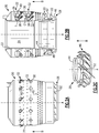
- the propulsion system 10 includes a core engine article 30, which is an integral (unitary) structure that incorporates the combustor liner 22 and turbine nozzle 26.
- Known combustors may include dozens of separate components.
- the present core engine article 30 is a single, integral (unitary) piece formed by additive manufacturing, which is discussed in more detail below.
- the combustor liner 22 is generally annular in shape and includes a plurality of injector ports 32 through which atomized fuel is injected into the combustion chamber 24.
- the injector ports 32 have a shape and location/arrangement that are configured to be fabricated by additive manufacturing, as is discussed in more detail below.
- the injector ports 32 are diamond-shaped. However, other shapes are contemplated.
- the injector ports 32 include a wall 36 that circumscribes an interior passage and corresponds to an opening 38. That is, the wall 36 has a tubular shape that tracks the circumferential shape of the opening 38. In the example of Figure 2A-B , the wall 36 has one end that extends into the combustion chamber 24 to an extent past the inner surface of the combustor liner 22 and a second end that is flush with an outer wall of the combustor liner 22.
- a webbing 40 extends outward from the combustor liner 22 along at least a portion of the periphery of the injector ports 32.
- the webbing 40 acts as a support for fuel injectors (not shown) which provide the atomized fuel, and facilitate unimpeded combustion within the combustion chamber 24.
- the webbing 40 extends along less than the entire circumference of the injector ports 32.
- the combustor liner 22 also includes a plurality of cooling holes 42.
- the cooling holes 42 can have varying sizes and arrangements around the combustor liner 22.
- the cooling holes 42 are round and have varying diameters. In other examples, other shapes and diameters can be used.
- the turbine nozzle 26 has an inner annulus 44 and an outer annulus 46.
- An aft end of the combustor liner 22 is interposed between the inner annulus 44 and the outer annulus 46 relative to a central axis A of the propulsion system 10.
- a rib 48 extends circumferentially around an outer surface of the inner annulus 44 at an aft end of the inner annulus 44 (e.g., adjacent a meeting point of the inner annulus 44 and outer annulus 46).
- the rib 48 contacts the combustor liner 22 and sandwiches the combustor liner 22 between the rib 48 and outer annulus 46.
- An aft end of the liner 22 includes one or more scallop features 50, as best seen in Figure 2D .
- the scallops 50 are ramps that increase the radius of the outer wall of the combustor liner 22 along the extent of the scallop 50 in the aft direction, towards the meeting point of the inner annulus 44 and the outer annulus 46 of the turbine nozzle 26.
- the ramp shape of the scallops 50 accelerates air as it flows past the scallops 50 and into space between the aft end of the combustor liner 22 and the inner annulus 44 in an aftward direction.
- the acceleration of the air allows it to reverse directions and flows out of the space (in a forward direction) and back into the combustion chamber 24. Directing air back into the combustion chamber 24 in this manner improves the combustion efficiency of the combustor 16 because it minimizes air (oxygen) loss.
- the outer annulus 46 has a plurality of dihedral airfoils 52 arranged circumferentially.
- the dihedral airfoils 52 have a geometry and location/ arrangement that meets the performance requirements of the propulsion system 10 and are configured to be fabricated by additive manufacturing, which is discussed in more detail below.
- the dihedral airfoils 52 extend along an axis D which is angled with respect to the central engine axis A and build direction B.
- the core engine article 30 is manufactured by an additive manufacturing technique.
- Additive manufacturing involves building an article layer-by-layer from a powder material by consolidating selected portions of each successive layer of powder until the complete article is formed.
- the powder is fed into a chamber, which may be under vacuum or inert cover gas.
- a machine deposits multiple layers of the powder onto one another.
- An energy beam such as a laser, selectively heats and consolidates each layer with reference to a computer-aided design data to form solid structures that relate to a particular cross-section of the article.
- Other layers or portions of layers corresponding to negative features, such as cavities or openings, are not joined and thus remain as a powdered material.
- the unjoined powder material may later be removed using blown air, for example.
- the article With the layers built upon one another and joined to one another cross-section by cross-section, the article is produced.
- the article may be post-processed to provide desired structural characteristics.
- the article may be heat treated to produce a desired microstructure.
- Additive manufacturing processes can include, but are not limited to, selective laser melting, direct metal laser sintering, electron beam melting, 3D printing, laser engineered net shaping, or laser powder forming.
- the core engine article 30 is seamless with regard to distinct boundaries that would otherwise be formed using techniques such as welding or brazing.
- the (monolithic) core engine article 30, in one example is free of seams such that there are no distinct boundaries or discontinuities in the core engine article 30 that are visually or microscopically discernable.
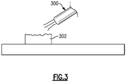
- Figure 3 schematically shows an example additive manufacturing tool 300, such as a laser, which can print a component 302 by any of the additive manufacturing techniques described above or another additive manufacturing technique.
- the additive manufacturing tool 300 is printing the core engine article 30 described above, however, the additive manufacturing tool 300 can print any of the structures described herein.
- Additive manufacturing of the core engine article 30 proceeds in a build direction B as shown in Figures 2A-C .
- relatively complex shapes can be achieved using additive manufacturing.
- the structures that are being built must be self-supporting. Otherwise, the article may break or warp, which may also damage the additive manufacturing equipment.
- structures that cantilever perpendicularly from the built direction are often not self-supporting and thus increase the risk of fracture or warping.
- the core engine article 30 is an integration of two functional sections, here the liner 22 and the nozzle 26, the configurations of the sections are adapted to be formed by additive manufacturing, as discussed further below.
- the core engine article 30 thus represents a substantial redesign of the functional sections to achieve both good performance and manufacturability by additive manufacturing.
- the build direction B is parallel to the central engine axis A. As shown, the build begins with the turbine nozzle 26 and proceeds to the combustor liner 22 with injector ports 32. The turbine nozzle 26 supports the combustor liner 22 during the build.
- the shape and location/arrangement of the injector ports 32 is selected to meet the performance requirements of the propulsion system. Still, the shape and location/arrangement of the injector ports 32 are configured to be fabricated by additive manufacturing. For instance, additive manufacturing techniques can be used to create circular holes in a build piece with diameters up to about 0.254 cm (0.1 in). For circular holes greater than about 0.254 cm (0.1 in) in diameter, a build piece manufactured with additive manufacturing can exhibit undesirable surface roughness on the top (downward-facing) surface of the hole with respect to the build direction B. The undesirable surface roughness is related to the angle of curvature of the downward-facing surface with respect to the build direction.
- hole shapes which taper to a corner on the top (downward-facing) surface of the hole with respect to the build direction B do not exhibit the surface roughness problem with a maximum dimension larger than 0.254 cm (0.1 in). This is because the angle of curvature of the downward-facing surface is small enough to avoid the material movement/shifting discussed above.
- the top, downward-facing surface corresponds to an aft surface in relation to the propulsion system 10 and axis A.
- the injector ports 32 have a diamond-shaped geometry wherein the top/aft surface of the wall 36 tapers to a corner C1 and the bottom/forward surface of the wall 36 tapers to a corner C2.
- Another example shape is a teardrop shape, with the top surface of the wall tapering to a point and a bottom/forward surface of the wall having a rounded shape.
- the injector ports 32 have a maximum dimension larger than 0.1 inches.
- the wall 36 has a thickness T that extends between an inner and outer surface of the wall.
- the outer surface of the wall may or may not track the same shape as the inner surface of the wall.
- the outer surface of the wall has a more rounded shape than the inner surface of the wall, which has corners C1 and C2.
- the dihedral airfoils 52 have a geometry that is configured to be formed by additive manufacturing.
- the dihedral airfoils 52 extend along an axis D with respect to the central engine axis A.
- the dihedral airfoils 52 must have enough structural integrity and be arranged with respect to the body of the turbine nozzle 26 so that they are self-supporting.
- the dihedral airfoils 52 extend outward from the turbine nozzle 26 but do not reach the very bottom surface of the turbine nozzle 26 (which corresponds to an aft end of the turbine nozzle 26) from which the build proceeds.
- the dihedral airfoils 52 extend out from the turbine nozzle 26 without support.
- the angle ⁇ of the axis D with respect to the central engine axis A/build direction B is selected to ensure that the dihedral airfoils 52 are self-supporting during the build. If the angle ⁇ is too small, e.g., the dihedral airfoils 52 are essentially parallel to the central engine axis, the dihedral airfoils 52 cannot support themselves during the build and can collapse or have imperfections in the material deposited by additive manufacturing that can be subject to thermal distortion during operation of the propulsion system 10.
- the angle ⁇ is greater than about 32 degrees. In a further example, the angle ⁇ is about 45 degrees.
- Additive manufacturing of the core engine article 30 allows for unitizing of propulsion system 10 assemblies, integrates complex performance-enhancing features of the propulsion system 10 with one another, lowers production costs, reduces manufacturing and assembly time/complexity, and allows for quick design changes/iterations when necessary. These benefits are particularly important to attritable/expendable systems because of the low cost-target and assembly effort requirements.
- the additive manufacturing technique allows for the formation of certain small and/or geometrically complex features such as the injector ports 32 and dihedral airfoils 52 that would be difficult or impossible to form with a traditional casting process.
Landscapes
- Engineering & Computer Science (AREA)
- Mechanical Engineering (AREA)
- General Engineering & Computer Science (AREA)
- Chemical & Material Sciences (AREA)
- Combustion & Propulsion (AREA)
- Manufacturing & Machinery (AREA)
- Materials Engineering (AREA)
- Turbine Rotor Nozzle Sealing (AREA)
- Powder Metallurgy (AREA)
Claims (15)
- Kerntriebwerksartikel (30), umfassend:eine Brennkammerwand (22), die darin eine Verbrennungskammer (24) definiert, undeine Turbinendüse (26), wobei die Turbinendüse (26) eine Vielzahl von Schaufelprofilen (52) einschließt, wobei die Brennkammerwand (22) und die Turbinendüse (26) miteinander einstückig sind und additiv gefertigt werden;dadurch gekennzeichnet, dassdie Brennkammerwand (22) eine Vielzahl von Kraftstoffeinspritzöffnungen (32) einschließt, wobei die Vielzahl von Kraftstoffeinspritzöffnungen (32) eine Form aufweist, die sich zu einer Ecke an einer Vorderseite der Kraftstoffeinspritzöffnungen (32) hin verjüngt.
- Kerntriebwerksartikel (30) nach Anspruch 1, wobei die Vielzahl von Kraftstoffeinspritzöffnungen (32) eine maximale Abmessung aufweist, die größer als 0,254 cm (0,1 in) ist.
- Kerntriebwerksartikel (30) nach Anspruch 1 oder 2, wobei die Kraftstoffeinspritzöffnungen (32) rautenförmig sind.
- Kerntriebwerksartikel (30) nach Anspruch 1, 2 oder 3, ferner umfassend ein Gewebe (40), das sich von der Brennkammerwand (22) entlang einer Erstreckung eines Umfangs der Kraftstoffeinspritzöffnungen (32) nach außen erstreckt.
- Kerntriebwerksartikel (30) nach einem vorhergehenden Anspruch, wobei sich die Kraftstoffeinspritzöffnungen (32) in die Verbrennungskammer (24) erstrecken.
- Kerntriebwerksartikel (30) nach Anspruch 1, wobei die Schaufelprofile (52) jeweils entlang einer Schaufelprofilachse (D) angeordnet sind, und ein Winkel α zwischen der Schaufelprofilachse (D) und einer Mittelachse (A) des Kerntriebwerksartikels (30) größer ist als 32 Grad.
- Kerntriebwerksartikel (30) nach Anspruch 5, wobei der Winkel α ungefähr 45 Grad beträgt.
- Kerntriebwerksartikel (30) nach einem vorhergehenden Anspruch, wobei die Turbinendüse (26) einen inneren Ring (44) und einen äußeren Ring (46) einschließt, wobei sich der innere Ring (44) in die Verbrennungskammer (24) erstreckt, und die Brennkammerwand (22) zwischen dem inneren Ring (44) und dem äußeren Ring (46) angeordnet ist.
- Kerntriebwerksartikel (30) nach Anspruch 8, wobei eine Lippe oder Rippe (48), die sich von dem inneren Ring (44) erstreckt, die Brennkammerwand (22) berührt.
- Kerntriebwerksartikel (30) nach Anspruch 8 oder 9, wobei sich die Schaufelprofile (52) von einer Außenseite des äußeren Rings (46) erstrecken.
- Kerntriebwerksartikel (30) nach einem vorhergehenden Anspruch, wobei ein hinteres Ende der Brennkammerwand (22) einen oder mehrere Grate (50) einschließt.
- Kerntriebwerksartikel (30) nach Anspruch 11, wobei die Grate (50) konfiguriert sind, um Luft zu beschleunigen, die durch den Kerntriebwerksartikel (30) strömt.
- Verfahren zur Herstellung eines Kerntriebwerksartikels (30), umfassend:Aufbringen von Material unter Verwendung einer Methode zur additiven Fertigung, um eine Turbinendüse (26) in einer Erstellungsrichtung (B) zu formen; undAufbringen von Material unter Verwendung der Methode zur additiven Fertigung, um eine Brennkammerwand (22) in der Erstellungsrichtung (B) zu formen, wobei die Brennkammerwand (22) während der Erstellung von der Turbinendüse (26) gestützt wird,dadurch gekennzeichnet, dassdas Formen der Brennkammerwand (22) das Formen einer Vielzahl von Kraftstoffeinspritzöffnungen (32) einschließt, wobei die Kraftstoffeinspritzöffnungen (32) eine maximale Abmessung aufweisen, die größer als 0,254 cm (0,1 in) ist und die Vielzahl von Kraftstoffeinspritzöffnungen (32) eine Form aufweist, die sich zu einer Ecke an einer Oberseite in Bezug auf die Erstellungsrichtung (B) hin verjüngt.
- Verfahren nach Anspruch 13, wobei das Formen der Turbinendüse (26) das Formen einer Vielzahl von Schaufelprofilen (52) an einer Außenfläche der Turbinendüse (26) einschließt, wobei die Schaufelprofile (52) eine Ausrichtung in Bezug auf die Erstellungsrichtung (B) aufweisen, sodass sie während der Erstellung selbsttragend sind.
- Verfahren nach Anspruch 14, wobei die Schaufelprofile (52) jeweils entlang einer Schaufelprofilachse (D) erstellt werden, und ein Winkel α zwischen der Schaufelprofilachse (D) und der Erstellungsrichtung (B) größer als 32 Grad ist.
Applications Claiming Priority (1)
| Application Number | Priority Date | Filing Date | Title |
|---|---|---|---|
| US16/212,879 US11248789B2 (en) | 2018-12-07 | 2018-12-07 | Gas turbine engine with integral combustion liner and turbine nozzle |
Publications (2)
| Publication Number | Publication Date |
|---|---|
| EP3663650A1 EP3663650A1 (de) | 2020-06-10 |
| EP3663650B1 true EP3663650B1 (de) | 2021-08-25 |
Family
ID=68835044
Family Applications (1)
| Application Number | Title | Priority Date | Filing Date |
|---|---|---|---|
| EP19214300.6A Active EP3663650B1 (de) | 2018-12-07 | 2019-12-06 | Gasturbinenmotorartikel mit additiv gefertigter integraler brennkammerwand und düse |
Country Status (2)
| Country | Link |
|---|---|
| US (3) | US11248789B2 (de) |
| EP (1) | EP3663650B1 (de) |
Families Citing this family (6)
| Publication number | Priority date | Publication date | Assignee | Title |
|---|---|---|---|---|
| US20220316400A1 (en) * | 2021-04-02 | 2022-10-06 | Raytheon Technologies Corporation | Turbine engine fuel injector with non-circular nozzle passage |
| US11732610B2 (en) * | 2021-11-24 | 2023-08-22 | Raytheon Technologies Corporation | Sectioned engine structure for a gas turbine engine |
| CN115143487A (zh) * | 2022-06-23 | 2022-10-04 | 中国航发贵阳发动机设计研究所 | 一种用于轴向进气涡流器的安装结构 |
| US11846249B1 (en) * | 2022-09-02 | 2023-12-19 | Rtx Corporation | Gas turbine engine with integral bypass duct |
| US12013120B1 (en) | 2023-06-30 | 2024-06-18 | Rtx Corporation | Turbine engine support structure with airflow ports |
| US12546227B2 (en) * | 2024-02-09 | 2026-02-10 | Rtx Corporation | Cooling nozzle vanes of a turbine engine |
Family Cites Families (82)
| Publication number | Priority date | Publication date | Assignee | Title |
|---|---|---|---|---|
| GB1243630A (en) * | 1967-11-07 | 1971-08-25 | Charles David Hope-Gill | Power plant including a gas turbine |
| US4301657A (en) * | 1978-05-04 | 1981-11-24 | Caterpillar Tractor Co. | Gas turbine combustion chamber |
| US4314443A (en) * | 1978-11-08 | 1982-02-09 | Teledyne Industries, Inc. | Turbine engine construction |
| US4844692A (en) * | 1988-08-12 | 1989-07-04 | Avco Corporation | Contoured step entry rotor casing |
| US5220794A (en) * | 1988-12-12 | 1993-06-22 | Sundstrand Corporation | Improved fuel injector for a gas turbine engine |
| US4926630A (en) * | 1988-12-12 | 1990-05-22 | Sundstrand Corporation | Jet air cooled turbine shroud for improved swirl cooling and mixing |
| US4967563A (en) * | 1988-12-12 | 1990-11-06 | Sundstrand Corporation | Turbine engine with high efficiency fuel atomization |
| US5022817A (en) * | 1989-09-12 | 1991-06-11 | Allied-Signal Inc. | Thermostatic control of turbine cooling air |
| US5263316A (en) * | 1989-12-21 | 1993-11-23 | Sundstrand Corporation | Turbine engine with airblast injection |
| US5277022A (en) * | 1990-06-22 | 1994-01-11 | Sundstrand Corporation | Air blast fuel injecton system |
| FR2674317B1 (fr) * | 1991-03-20 | 1993-05-28 | Snecma | Chambre de combustion de turbomachine comportant un reglage du debit de comburant. |
| US5317864A (en) * | 1992-09-30 | 1994-06-07 | Sundstrand Corporation | Tangentially directed air assisted fuel injection and small annular combustors for turbines |
| GB9407029D0 (en) * | 1994-04-08 | 1994-06-08 | Rolls Royce Plc | Gas turbine engine combustion apparatus |
| US5932940A (en) * | 1996-07-16 | 1999-08-03 | Massachusetts Institute Of Technology | Microturbomachinery |
| DE19651881A1 (de) | 1996-12-13 | 1998-06-18 | Asea Brown Boveri | Brennkammer mit integrierten Leitschaufeln |
| US6351949B1 (en) * | 1999-09-03 | 2002-03-05 | Allison Advanced Development Company | Interchangeable combustor chute |
| US6675587B2 (en) * | 2002-03-21 | 2004-01-13 | United Technologies Corporation | Counter swirl annular combustor |
| US6729141B2 (en) * | 2002-07-03 | 2004-05-04 | Elliot Energy Systems, Inc. | Microturbine with auxiliary air tubes for NOx emission reduction |
| GB2399408B (en) * | 2003-03-14 | 2006-02-22 | Rolls Royce Plc | Gas turbine engine combustor |
| US6931862B2 (en) * | 2003-04-30 | 2005-08-23 | Hamilton Sundstrand Corporation | Combustor system for an expendable gas turbine engine |
| JP4346412B2 (ja) * | 2003-10-31 | 2009-10-21 | 株式会社東芝 | タービン翼列装置 |
| US7217096B2 (en) * | 2004-12-13 | 2007-05-15 | General Electric Company | Fillet energized turbine stage |
| US7134842B2 (en) * | 2004-12-24 | 2006-11-14 | General Electric Company | Scalloped surface turbine stage |
| US7249933B2 (en) * | 2005-01-10 | 2007-07-31 | General Electric Company | Funnel fillet turbine stage |
| US7220100B2 (en) * | 2005-04-14 | 2007-05-22 | General Electric Company | Crescentic ramp turbine stage |
| US7594388B2 (en) * | 2005-06-06 | 2009-09-29 | General Electric Company | Counterrotating turbofan engine |
| US8884182B2 (en) * | 2006-12-11 | 2014-11-11 | General Electric Company | Method of modifying the end wall contour in a turbine using laser consolidation and the turbines derived therefrom |
| GB2444736B (en) * | 2006-12-12 | 2009-06-03 | Rolls Royce Plc | Combustion Chamber Air Inlet |
| US7930891B1 (en) | 2007-05-10 | 2011-04-26 | Florida Turbine Technologies, Inc. | Transition duct with integral guide vanes |
| CA2737516A1 (en) * | 2008-09-18 | 2010-03-25 | Siemens Aktiengesellschaft | Method, system, device for variable guide vanes |
| US8171740B2 (en) * | 2009-02-27 | 2012-05-08 | Honeywell International Inc. | Annular rich-quench-lean gas turbine combustors with plunged holes |
| DE102010023816A1 (de) * | 2010-06-15 | 2011-12-15 | Rolls-Royce Deutschland Ltd & Co Kg | Gasturbinenbrennkammeranordnung |
| US9062884B2 (en) * | 2011-05-26 | 2015-06-23 | Honeywell International Inc. | Combustors with quench inserts |
| US8966910B2 (en) * | 2011-06-21 | 2015-03-03 | General Electric Company | Methods and systems for cooling a transition nozzle |
| US8919137B2 (en) * | 2011-08-05 | 2014-12-30 | General Electric Company | Assemblies and apparatus related to integrating late lean injection into combustion turbine engines |
| US9243506B2 (en) * | 2012-01-03 | 2016-01-26 | General Electric Company | Methods and systems for cooling a transition nozzle |
| FR2992018B1 (fr) | 2012-06-15 | 2016-05-06 | Snecma | Montage d'un distributeur de turbine haute-pression sur une chambre a combustion d'une turbomachine |
| US9404654B2 (en) | 2012-09-26 | 2016-08-02 | United Technologies Corporation | Gas turbine engine combustor with integrated combustor vane |
| US9482432B2 (en) | 2012-09-26 | 2016-11-01 | United Technologies Corporation | Gas turbine engine combustor with integrated combustor vane having swirler |
| US9194585B2 (en) * | 2012-10-04 | 2015-11-24 | United Technologies Corporation | Cooling for combustor liners with accelerating channels |
| US9803498B2 (en) * | 2012-10-17 | 2017-10-31 | United Technologies Corporation | One-piece fuel nozzle for a thrust engine |
| US9366187B2 (en) * | 2013-03-12 | 2016-06-14 | Pratt & Whitney Canada Corp. | Slinger combustor |
| FR3009588B1 (fr) * | 2013-08-07 | 2018-01-26 | Safran Aircraft Engines | Aube mobile de turbomachine |
| EP2957833B1 (de) * | 2014-06-17 | 2018-10-24 | Rolls-Royce Corporation | Brennkammeranordnung mit rinnen |
| US10371064B2 (en) * | 2015-02-26 | 2019-08-06 | General Electric Company | Method and system to increase gas turbine engine durability |
| DE102015212573A1 (de) | 2015-07-06 | 2017-01-12 | Rolls-Royce Deutschland Ltd & Co Kg | Gasturbinenbrennkammer mit integriertem Turbinenvorleitrad sowie Verfahren zu deren Herstellung |
| EP3325887A1 (de) * | 2015-07-24 | 2018-05-30 | Siemens Aktiengesellschaft | Gasturbinenübergangskanal mit später magergemischeinspritzung mit reduzierter verbrennungsverweilzeit |
| US10670267B2 (en) * | 2015-08-14 | 2020-06-02 | Raytheon Technologies Corporation | Combustor hole arrangement for gas turbine engine |
| US20170059159A1 (en) * | 2015-08-25 | 2017-03-02 | Rolls-Royce Corporation | Cmc combustor shell with integral chutes |
| WO2017074345A1 (en) * | 2015-10-28 | 2017-05-04 | Siemens Energy, Inc. | Combustion system with injector assembly including aerodynamically-shaped body and/or ejection orifices |
| US11428413B2 (en) * | 2016-03-25 | 2022-08-30 | General Electric Company | Fuel injection module for segmented annular combustion system |
| US10641176B2 (en) * | 2016-03-25 | 2020-05-05 | General Electric Company | Combustion system with panel fuel injector |
| US10563869B2 (en) * | 2016-03-25 | 2020-02-18 | General Electric Company | Operation and turndown of a segmented annular combustion system |
| US10584880B2 (en) * | 2016-03-25 | 2020-03-10 | General Electric Company | Mounting of integrated combustor nozzles in a segmented annular combustion system |
| US10584876B2 (en) * | 2016-03-25 | 2020-03-10 | General Electric Company | Micro-channel cooling of integrated combustor nozzle of a segmented annular combustion system |
| US10358934B2 (en) * | 2016-04-11 | 2019-07-23 | United Technologies Corporation | Method and apparatus for adjusting variable vanes |
| US20170370583A1 (en) * | 2016-06-22 | 2017-12-28 | General Electric Company | Ceramic Matrix Composite Component for a Gas Turbine Engine |
| US10605092B2 (en) * | 2016-07-11 | 2020-03-31 | United Technologies Corporation | Cooling hole with shaped meter |
| WO2018026382A1 (en) * | 2016-08-03 | 2018-02-08 | Siemens Aktiengesellschaft | Ducting arrangement with injector assemblies configured to form a shielding flow of air injected into a combustion stage in a gas turbine engine |
| EP3472518B1 (de) * | 2016-09-27 | 2020-11-18 | Siemens Aktiengesellschaft | Axialstufenverbrennung von kraftstofföl für verbesserte turbinenbrennleistung |
| US10221769B2 (en) * | 2016-12-02 | 2019-03-05 | General Electric Company | System and apparatus for gas turbine combustor inner cap and extended resonating tubes |
| US10220474B2 (en) * | 2016-12-02 | 2019-03-05 | General Electricd Company | Method and apparatus for gas turbine combustor inner cap and high frequency acoustic dampers |
| US10513987B2 (en) * | 2016-12-30 | 2019-12-24 | General Electric Company | System for dissipating fuel egress in fuel supply conduit assemblies |
| US10393381B2 (en) * | 2017-01-27 | 2019-08-27 | General Electric Company | Unitary flow path structure |
| US10253643B2 (en) * | 2017-02-07 | 2019-04-09 | General Electric Company | Airfoil fluid curtain to mitigate or prevent flow path leakage |
| US10385709B2 (en) * | 2017-02-23 | 2019-08-20 | General Electric Company | Methods and features for positioning a flow path assembly within a gas turbine engine |
| US10378373B2 (en) * | 2017-02-23 | 2019-08-13 | General Electric Company | Flow path assembly with airfoils inserted through flow path boundary |
| US10370990B2 (en) * | 2017-02-23 | 2019-08-06 | General Electric Company | Flow path assembly with pin supported nozzle airfoils |
| US10253641B2 (en) * | 2017-02-23 | 2019-04-09 | General Electric Company | Methods and assemblies for attaching airfoils within a flow path |
| US10767564B2 (en) * | 2017-03-17 | 2020-09-08 | Hamilton Sunstrand Corporation | Air turbine starter with automated variable inlet vanes |
| US10385731B2 (en) * | 2017-06-12 | 2019-08-20 | General Electric Company | CTE matching hanger support for CMC structures |
| US11561008B2 (en) * | 2017-08-23 | 2023-01-24 | General Electric Company | Fuel nozzle assembly for high fuel/air ratio and reduced combustion dynamics |
| US11137144B2 (en) * | 2017-12-11 | 2021-10-05 | General Electric Company | Axial fuel staging system for gas turbine combustors |
| JP6956035B2 (ja) * | 2018-03-20 | 2021-10-27 | 三菱重工業株式会社 | 燃焼器 |
| CN108590859B (zh) | 2018-04-24 | 2021-03-09 | 深圳意动航空科技有限公司 | 一种增材制造的微型涡喷发动机 |
| US10941944B2 (en) * | 2018-10-04 | 2021-03-09 | Raytheon Technologies Corporation | Consumable support structures for additively manufactured combustor components |
| US20200191061A1 (en) * | 2018-12-17 | 2020-06-18 | United Technologies Corporation | Integrated additive bladder for charging and insulation of small attritable engine |
| US11085639B2 (en) * | 2018-12-27 | 2021-08-10 | Rolls-Royce North American Technologies Inc. | Gas turbine combustor liner with integral chute made by additive manufacturing process |
| US11136901B2 (en) * | 2019-05-17 | 2021-10-05 | Raytheon Technologies Corporation | Monolithic combustor for attritiable engine applications |
| US11885497B2 (en) * | 2019-07-19 | 2024-01-30 | Pratt & Whitney Canada Corp. | Fuel nozzle with slot for cooling |
| US11262077B2 (en) * | 2019-09-20 | 2022-03-01 | Raytheon Technologies Corporation | Spall plate for consumable combustor support structures |
| US12595907B2 (en) * | 2019-11-22 | 2026-04-07 | Rtx Corporation | Inspection port for an attritable engine support structure |
-
2018
- 2018-12-07 US US16/212,879 patent/US11248789B2/en active Active
-
2019
- 2019-12-06 EP EP19214300.6A patent/EP3663650B1/de active Active
-
2022
- 2022-02-02 US US17/591,054 patent/US11612938B2/en active Active
-
2023
- 2023-03-16 US US18/122,207 patent/US12053821B2/en active Active
Also Published As
| Publication number | Publication date |
|---|---|
| US20220221151A1 (en) | 2022-07-14 |
| US11612938B2 (en) | 2023-03-28 |
| US11248789B2 (en) | 2022-02-15 |
| EP3663650A1 (de) | 2020-06-10 |
| US20200182467A1 (en) | 2020-06-11 |
| US20230241681A1 (en) | 2023-08-03 |
| US12053821B2 (en) | 2024-08-06 |
Similar Documents
| Publication | Publication Date | Title |
|---|---|---|
| EP3663650B1 (de) | Gasturbinenmotorartikel mit additiv gefertigter integraler brennkammerwand und düse | |
| EP2772688B1 (de) | Schaufelstruktur und Verfahren zur Herstellung einer Schaufelstruktur | |
| US10533747B2 (en) | Additively manufactured mechanical fastener with cooling fluid passageways | |
| US11131247B2 (en) | Additively manufactured rotating shaft | |
| EP2759772B1 (de) | Brenner mit komplex geformten Effusionskühlöffnungen | |
| EP3062021B1 (de) | Brennstoffdüse | |
| EP3052784B1 (de) | Additiv gefertigter brennstoffdüsenkern für einen gasturbinenmotor | |
| EP2841702B1 (de) | Schaufel mit konischen stützen | |
| EP3242085B1 (de) | Brennkammerwand und verfahren zur herstellung einer brennkammerwand | |
| US10982851B2 (en) | Additively manufactured wall and floating ferrule having a frangible member between the floating ferrule and a build support arm | |
| US10781721B2 (en) | Integral turbine center frame | |
| US20180156056A1 (en) | Additive manufactured case with internal passages for active clearance control | |
| US20220162963A1 (en) | Additively Manufactured Component Including an Impingement Structure | |
| US10837293B2 (en) | Airfoil with tunable cooling configuration | |
| EP2841707B1 (de) | Schaufel mit mindestabstandsrippen und verfahren zur bearbeitung einer schaufel | |
| EP3663563B1 (de) | Gehäuse mit integralem hohlraum | |
| EP3795902B1 (de) | Tragstruktur für brennkammerkomponenten und verfahren zur verwendung davon |
Legal Events
| Date | Code | Title | Description |
|---|---|---|---|
| PUAI | Public reference made under article 153(3) epc to a published international application that has entered the european phase |
Free format text: ORIGINAL CODE: 0009012 |
|
| STAA | Information on the status of an ep patent application or granted ep patent |
Free format text: STATUS: THE APPLICATION HAS BEEN PUBLISHED |
|
| AK | Designated contracting states |
Kind code of ref document: A1 Designated state(s): AL AT BE BG CH CY CZ DE DK EE ES FI FR GB GR HR HU IE IS IT LI LT LU LV MC MK MT NL NO PL PT RO RS SE SI SK SM TR |
|
| AX | Request for extension of the european patent |
Extension state: BA ME |
|
| STAA | Information on the status of an ep patent application or granted ep patent |
Free format text: STATUS: REQUEST FOR EXAMINATION WAS MADE |
|
| 17P | Request for examination filed |
Effective date: 20201210 |
|
| RBV | Designated contracting states (corrected) |
Designated state(s): AL AT BE BG CH CY CZ DE DK EE ES FI FR GB GR HR HU IE IS IT LI LT LU LV MC MK MT NL NO PL PT RO RS SE SI SK SM TR |
|
| GRAP | Despatch of communication of intention to grant a patent |
Free format text: ORIGINAL CODE: EPIDOSNIGR1 |
|
| STAA | Information on the status of an ep patent application or granted ep patent |
Free format text: STATUS: GRANT OF PATENT IS INTENDED |
|
| RAP1 | Party data changed (applicant data changed or rights of an application transferred) |
Owner name: RAYTHEON TECHNOLOGIES CORPORATION |
|
| RIC1 | Information provided on ipc code assigned before grant |
Ipc: B22F 5/00 20060101AFI20210217BHEP Ipc: B22F 10/20 20210101ALI20210217BHEP Ipc: F01D 25/24 20060101ALI20210217BHEP Ipc: F23R 3/30 20060101ALI20210217BHEP Ipc: F02C 7/22 20060101ALI20210217BHEP Ipc: F23R 3/00 20060101ALI20210217BHEP Ipc: F23R 3/28 20060101ALI20210217BHEP |
|
| RIC1 | Information provided on ipc code assigned before grant |
Ipc: F02C 7/22 20060101ALI20210225BHEP Ipc: F02C 3/08 20060101ALI20210225BHEP Ipc: F23R 3/28 20060101ALI20210225BHEP Ipc: F01D 9/02 20060101ALI20210225BHEP Ipc: F02C 3/045 20060101ALI20210225BHEP Ipc: F02C 3/14 20060101ALI20210225BHEP Ipc: F23R 3/00 20060101AFI20210225BHEP Ipc: B22F 5/00 20060101ALI20210225BHEP Ipc: F01D 25/24 20060101ALI20210225BHEP Ipc: B22F 10/20 20210101ALI20210225BHEP Ipc: F23R 3/30 20060101ALI20210225BHEP |
|
| INTG | Intention to grant announced |
Effective date: 20210310 |
|
| RIN1 | Information on inventor provided before grant (corrected) |
Inventor name: BOYER, JESSE R. Inventor name: BINEK, LAWRENCE Inventor name: VOYTOVYCH, DEMYTRO MYKOLAYOVYCH |
|
| GRAS | Grant fee paid |
Free format text: ORIGINAL CODE: EPIDOSNIGR3 |
|
| GRAA | (expected) grant |
Free format text: ORIGINAL CODE: 0009210 |
|
| STAA | Information on the status of an ep patent application or granted ep patent |
Free format text: STATUS: THE PATENT HAS BEEN GRANTED |
|
| AK | Designated contracting states |
Kind code of ref document: B1 Designated state(s): AL AT BE BG CH CY CZ DE DK EE ES FI FR GB GR HR HU IE IS IT LI LT LU LV MC MK MT NL NO PL PT RO RS SE SI SK SM TR |
|
| REG | Reference to a national code |
Ref country code: CH Ref legal event code: EP |
|
| REG | Reference to a national code |
Ref country code: IE Ref legal event code: FG4D Ref country code: AT Ref legal event code: REF Ref document number: 1424175 Country of ref document: AT Kind code of ref document: T Effective date: 20210915 |
|
| REG | Reference to a national code |
Ref country code: DE Ref legal event code: R096 Ref document number: 602019007176 Country of ref document: DE |
|
| REG | Reference to a national code |
Ref country code: LT Ref legal event code: MG9D |
|
| REG | Reference to a national code |
Ref country code: NL Ref legal event code: MP Effective date: 20210825 |
|
| REG | Reference to a national code |
Ref country code: AT Ref legal event code: MK05 Ref document number: 1424175 Country of ref document: AT Kind code of ref document: T Effective date: 20210825 |
|
| PG25 | Lapsed in a contracting state [announced via postgrant information from national office to epo] |
Ref country code: SE Free format text: LAPSE BECAUSE OF FAILURE TO SUBMIT A TRANSLATION OF THE DESCRIPTION OR TO PAY THE FEE WITHIN THE PRESCRIBED TIME-LIMIT Effective date: 20210825 Ref country code: RS Free format text: LAPSE BECAUSE OF FAILURE TO SUBMIT A TRANSLATION OF THE DESCRIPTION OR TO PAY THE FEE WITHIN THE PRESCRIBED TIME-LIMIT Effective date: 20210825 Ref country code: ES Free format text: LAPSE BECAUSE OF FAILURE TO SUBMIT A TRANSLATION OF THE DESCRIPTION OR TO PAY THE FEE WITHIN THE PRESCRIBED TIME-LIMIT Effective date: 20210825 Ref country code: FI Free format text: LAPSE BECAUSE OF FAILURE TO SUBMIT A TRANSLATION OF THE DESCRIPTION OR TO PAY THE FEE WITHIN THE PRESCRIBED TIME-LIMIT Effective date: 20210825 Ref country code: HR Free format text: LAPSE BECAUSE OF FAILURE TO SUBMIT A TRANSLATION OF THE DESCRIPTION OR TO PAY THE FEE WITHIN THE PRESCRIBED TIME-LIMIT Effective date: 20210825 Ref country code: PT Free format text: LAPSE BECAUSE OF FAILURE TO SUBMIT A TRANSLATION OF THE DESCRIPTION OR TO PAY THE FEE WITHIN THE PRESCRIBED TIME-LIMIT Effective date: 20211227 Ref country code: NO Free format text: LAPSE BECAUSE OF FAILURE TO SUBMIT A TRANSLATION OF THE DESCRIPTION OR TO PAY THE FEE WITHIN THE PRESCRIBED TIME-LIMIT Effective date: 20211125 Ref country code: AT Free format text: LAPSE BECAUSE OF FAILURE TO SUBMIT A TRANSLATION OF THE DESCRIPTION OR TO PAY THE FEE WITHIN THE PRESCRIBED TIME-LIMIT Effective date: 20210825 Ref country code: BG Free format text: LAPSE BECAUSE OF FAILURE TO SUBMIT A TRANSLATION OF THE DESCRIPTION OR TO PAY THE FEE WITHIN THE PRESCRIBED TIME-LIMIT Effective date: 20211125 Ref country code: LT Free format text: LAPSE BECAUSE OF FAILURE TO SUBMIT A TRANSLATION OF THE DESCRIPTION OR TO PAY THE FEE WITHIN THE PRESCRIBED TIME-LIMIT Effective date: 20210825 |
|
| PG25 | Lapsed in a contracting state [announced via postgrant information from national office to epo] |
Ref country code: PL Free format text: LAPSE BECAUSE OF FAILURE TO SUBMIT A TRANSLATION OF THE DESCRIPTION OR TO PAY THE FEE WITHIN THE PRESCRIBED TIME-LIMIT Effective date: 20210825 Ref country code: LV Free format text: LAPSE BECAUSE OF FAILURE TO SUBMIT A TRANSLATION OF THE DESCRIPTION OR TO PAY THE FEE WITHIN THE PRESCRIBED TIME-LIMIT Effective date: 20210825 Ref country code: GR Free format text: LAPSE BECAUSE OF FAILURE TO SUBMIT A TRANSLATION OF THE DESCRIPTION OR TO PAY THE FEE WITHIN THE PRESCRIBED TIME-LIMIT Effective date: 20211126 |
|
| PG25 | Lapsed in a contracting state [announced via postgrant information from national office to epo] |
Ref country code: NL Free format text: LAPSE BECAUSE OF FAILURE TO SUBMIT A TRANSLATION OF THE DESCRIPTION OR TO PAY THE FEE WITHIN THE PRESCRIBED TIME-LIMIT Effective date: 20210825 |
|
| PG25 | Lapsed in a contracting state [announced via postgrant information from national office to epo] |
Ref country code: DK Free format text: LAPSE BECAUSE OF FAILURE TO SUBMIT A TRANSLATION OF THE DESCRIPTION OR TO PAY THE FEE WITHIN THE PRESCRIBED TIME-LIMIT Effective date: 20210825 |
|
| REG | Reference to a national code |
Ref country code: DE Ref legal event code: R097 Ref document number: 602019007176 Country of ref document: DE |
|
| PG25 | Lapsed in a contracting state [announced via postgrant information from national office to epo] |
Ref country code: SM Free format text: LAPSE BECAUSE OF FAILURE TO SUBMIT A TRANSLATION OF THE DESCRIPTION OR TO PAY THE FEE WITHIN THE PRESCRIBED TIME-LIMIT Effective date: 20210825 Ref country code: SK Free format text: LAPSE BECAUSE OF FAILURE TO SUBMIT A TRANSLATION OF THE DESCRIPTION OR TO PAY THE FEE WITHIN THE PRESCRIBED TIME-LIMIT Effective date: 20210825 Ref country code: RO Free format text: LAPSE BECAUSE OF FAILURE TO SUBMIT A TRANSLATION OF THE DESCRIPTION OR TO PAY THE FEE WITHIN THE PRESCRIBED TIME-LIMIT Effective date: 20210825 Ref country code: EE Free format text: LAPSE BECAUSE OF FAILURE TO SUBMIT A TRANSLATION OF THE DESCRIPTION OR TO PAY THE FEE WITHIN THE PRESCRIBED TIME-LIMIT Effective date: 20210825 Ref country code: CZ Free format text: LAPSE BECAUSE OF FAILURE TO SUBMIT A TRANSLATION OF THE DESCRIPTION OR TO PAY THE FEE WITHIN THE PRESCRIBED TIME-LIMIT Effective date: 20210825 Ref country code: AL Free format text: LAPSE BECAUSE OF FAILURE TO SUBMIT A TRANSLATION OF THE DESCRIPTION OR TO PAY THE FEE WITHIN THE PRESCRIBED TIME-LIMIT Effective date: 20210825 |
|
| PLBE | No opposition filed within time limit |
Free format text: ORIGINAL CODE: 0009261 |
|
| STAA | Information on the status of an ep patent application or granted ep patent |
Free format text: STATUS: NO OPPOSITION FILED WITHIN TIME LIMIT |
|
| PG25 | Lapsed in a contracting state [announced via postgrant information from national office to epo] |
Ref country code: MC Free format text: LAPSE BECAUSE OF FAILURE TO SUBMIT A TRANSLATION OF THE DESCRIPTION OR TO PAY THE FEE WITHIN THE PRESCRIBED TIME-LIMIT Effective date: 20210825 Ref country code: IT Free format text: LAPSE BECAUSE OF FAILURE TO SUBMIT A TRANSLATION OF THE DESCRIPTION OR TO PAY THE FEE WITHIN THE PRESCRIBED TIME-LIMIT Effective date: 20210825 |
|
| 26N | No opposition filed |
Effective date: 20220527 |
|
| PG25 | Lapsed in a contracting state [announced via postgrant information from national office to epo] |
Ref country code: SI Free format text: LAPSE BECAUSE OF FAILURE TO SUBMIT A TRANSLATION OF THE DESCRIPTION OR TO PAY THE FEE WITHIN THE PRESCRIBED TIME-LIMIT Effective date: 20210825 |
|
| REG | Reference to a national code |
Ref country code: BE Ref legal event code: MM Effective date: 20211231 |
|
| PG25 | Lapsed in a contracting state [announced via postgrant information from national office to epo] |
Ref country code: LU Free format text: LAPSE BECAUSE OF NON-PAYMENT OF DUE FEES Effective date: 20211206 Ref country code: IE Free format text: LAPSE BECAUSE OF NON-PAYMENT OF DUE FEES Effective date: 20211206 |
|
| PG25 | Lapsed in a contracting state [announced via postgrant information from national office to epo] |
Ref country code: BE Free format text: LAPSE BECAUSE OF NON-PAYMENT OF DUE FEES Effective date: 20211231 |
|
| P01 | Opt-out of the competence of the unified patent court (upc) registered |
Effective date: 20230521 |
|
| PG25 | Lapsed in a contracting state [announced via postgrant information from national office to epo] |
Ref country code: CY Free format text: LAPSE BECAUSE OF FAILURE TO SUBMIT A TRANSLATION OF THE DESCRIPTION OR TO PAY THE FEE WITHIN THE PRESCRIBED TIME-LIMIT Effective date: 20210825 |
|
| PG25 | Lapsed in a contracting state [announced via postgrant information from national office to epo] |
Ref country code: HU Free format text: LAPSE BECAUSE OF FAILURE TO SUBMIT A TRANSLATION OF THE DESCRIPTION OR TO PAY THE FEE WITHIN THE PRESCRIBED TIME-LIMIT; INVALID AB INITIO Effective date: 20191206 |
|
| REG | Reference to a national code |
Ref country code: CH Ref legal event code: PL |
|
| PG25 | Lapsed in a contracting state [announced via postgrant information from national office to epo] |
Ref country code: LI Free format text: LAPSE BECAUSE OF NON-PAYMENT OF DUE FEES Effective date: 20221231 Ref country code: CH Free format text: LAPSE BECAUSE OF NON-PAYMENT OF DUE FEES Effective date: 20221231 |
|
| PG25 | Lapsed in a contracting state [announced via postgrant information from national office to epo] |
Ref country code: MK Free format text: LAPSE BECAUSE OF FAILURE TO SUBMIT A TRANSLATION OF THE DESCRIPTION OR TO PAY THE FEE WITHIN THE PRESCRIBED TIME-LIMIT Effective date: 20210825 |
|
| PG25 | Lapsed in a contracting state [announced via postgrant information from national office to epo] |
Ref country code: MT Free format text: LAPSE BECAUSE OF FAILURE TO SUBMIT A TRANSLATION OF THE DESCRIPTION OR TO PAY THE FEE WITHIN THE PRESCRIBED TIME-LIMIT Effective date: 20210825 |
|
| REG | Reference to a national code |
Ref country code: DE Ref legal event code: R081 Ref document number: 602019007176 Country of ref document: DE Owner name: RTX CORPORATION (N.D.GES.D. STAATES DELAWARE),, US Free format text: FORMER OWNER: RAYTHEON TECHNOLOGIES CORPORATION, FARMINGTON, CT, US |
|
| PG25 | Lapsed in a contracting state [announced via postgrant information from national office to epo] |
Ref country code: TR Free format text: LAPSE BECAUSE OF FAILURE TO SUBMIT A TRANSLATION OF THE DESCRIPTION OR TO PAY THE FEE WITHIN THE PRESCRIBED TIME-LIMIT Effective date: 20210825 |
|
| PGFP | Annual fee paid to national office [announced via postgrant information from national office to epo] |
Ref country code: DE Payment date: 20251126 Year of fee payment: 7 |
|
| PGFP | Annual fee paid to national office [announced via postgrant information from national office to epo] |
Ref country code: GB Payment date: 20251119 Year of fee payment: 7 |
|
| PGFP | Annual fee paid to national office [announced via postgrant information from national office to epo] |
Ref country code: FR Payment date: 20251120 Year of fee payment: 7 |