EP3663591A1 - Haken für einen hakenlader - Google Patents
Haken für einen hakenlader Download PDFInfo
- Publication number
- EP3663591A1 EP3663591A1 EP18210855.5A EP18210855A EP3663591A1 EP 3663591 A1 EP3663591 A1 EP 3663591A1 EP 18210855 A EP18210855 A EP 18210855A EP 3663591 A1 EP3663591 A1 EP 3663591A1
- Authority
- EP
- European Patent Office
- Prior art keywords
- hook
- wear indicator
- hookloader
- throat
- wear
- Prior art date
- Legal status (The legal status is an assumption and is not a legal conclusion. Google has not performed a legal analysis and makes no representation as to the accuracy of the status listed.)
- Granted
Links
Images



Classifications
-
- B—PERFORMING OPERATIONS; TRANSPORTING
- B66—HOISTING; LIFTING; HAULING
- B66C—CRANES; LOAD-ENGAGING ELEMENTS OR DEVICES FOR CRANES, CAPSTANS, WINCHES, OR TACKLES
- B66C1/00—Load-engaging elements or devices attached to lifting or lowering gear of cranes or adapted for connection therewith for transmitting lifting forces to articles or groups of articles
- B66C1/10—Load-engaging elements or devices attached to lifting or lowering gear of cranes or adapted for connection therewith for transmitting lifting forces to articles or groups of articles by mechanical means
- B66C1/22—Rigid members, e.g. L-shaped members, with parts engaging the under surface of the loads; Crane hooks
- B66C1/223—Rigid members, e.g. L-shaped members, with parts engaging the under surface of the loads; Crane hooks for containers
-
- B—PERFORMING OPERATIONS; TRANSPORTING
- B60—VEHICLES IN GENERAL
- B60P—VEHICLES ADAPTED FOR LOAD TRANSPORTATION OR TO TRANSPORT, TO CARRY, OR TO COMPRISE SPECIAL LOADS OR OBJECTS
- B60P1/00—Vehicles predominantly for transporting loads and modified to facilitate loading, consolidating the load, or unloading
- B60P1/64—Vehicles predominantly for transporting loads and modified to facilitate loading, consolidating the load, or unloading the load supporting or containing element being readily removable
- B60P1/6418—Vehicles predominantly for transporting loads and modified to facilitate loading, consolidating the load, or unloading the load supporting or containing element being readily removable the load-transporting element being a container or similar
- B60P1/6463—Vehicles predominantly for transporting loads and modified to facilitate loading, consolidating the load, or unloading the load supporting or containing element being readily removable the load-transporting element being a container or similar fitted with articulated beams for longitudinal displacement of the container
-
- B—PERFORMING OPERATIONS; TRANSPORTING
- B66—HOISTING; LIFTING; HAULING
- B66C—CRANES; LOAD-ENGAGING ELEMENTS OR DEVICES FOR CRANES, CAPSTANS, WINCHES, OR TACKLES
- B66C1/00—Load-engaging elements or devices attached to lifting or lowering gear of cranes or adapted for connection therewith for transmitting lifting forces to articles or groups of articles
- B66C1/10—Load-engaging elements or devices attached to lifting or lowering gear of cranes or adapted for connection therewith for transmitting lifting forces to articles or groups of articles by mechanical means
- B66C1/22—Rigid members, e.g. L-shaped members, with parts engaging the under surface of the loads; Crane hooks
- B66C1/34—Crane hooks
- B66C1/36—Crane hooks with means, e.g. spring-biased detents, for preventing inadvertent disengagement of loads
-
- B—PERFORMING OPERATIONS; TRANSPORTING
- B66—HOISTING; LIFTING; HAULING
- B66C—CRANES; LOAD-ENGAGING ELEMENTS OR DEVICES FOR CRANES, CAPSTANS, WINCHES, OR TACKLES
- B66C13/00—Other constructional features or details
- B66C13/16—Applications of indicating, registering, or weighing devices
-
- F—MECHANICAL ENGINEERING; LIGHTING; HEATING; WEAPONS; BLASTING
- F16—ENGINEERING ELEMENTS AND UNITS; GENERAL MEASURES FOR PRODUCING AND MAINTAINING EFFECTIVE FUNCTIONING OF MACHINES OR INSTALLATIONS; THERMAL INSULATION IN GENERAL
- F16B—DEVICES FOR FASTENING OR SECURING CONSTRUCTIONAL ELEMENTS OR MACHINE PARTS TOGETHER, e.g. NAILS, BOLTS, CIRCLIPS, CLAMPS, CLIPS OR WEDGES; JOINTS OR JOINTING
- F16B45/00—Hooks; Eyes
- F16B45/02—Hooks with pivoting or elastically bending closing member
- F16B45/023—Hooks with pivoting or elastically bending closing member the closing member pivoting about an axis perpendicular to the plane of the hook
-
- F—MECHANICAL ENGINEERING; LIGHTING; HEATING; WEAPONS; BLASTING
- F16—ENGINEERING ELEMENTS AND UNITS; GENERAL MEASURES FOR PRODUCING AND MAINTAINING EFFECTIVE FUNCTIONING OF MACHINES OR INSTALLATIONS; THERMAL INSULATION IN GENERAL
- F16B—DEVICES FOR FASTENING OR SECURING CONSTRUCTIONAL ELEMENTS OR MACHINE PARTS TOGETHER, e.g. NAILS, BOLTS, CIRCLIPS, CLAMPS, CLIPS OR WEDGES; JOINTS OR JOINTING
- F16B2200/00—Constructional details of connections not covered for in other groups of this subclass
- F16B2200/95—Constructional details of connections not covered for in other groups of this subclass with markings, colours, indicators or the like
Definitions
- the present invention concerns a hook for a hookloader.
- Hookloader vehicles are known which can pick-up and haul a container onto the back of the vehicle.
- a hookloader vehicle typically comprises a driver cab, a main chassis and a pivotable arm having a hook.
- One or more hydraulic cylinders are provided which can be actuated to pivot the arm with respect to the main chassis.
- a key component of a hookloader is the hook itself, which attaches the object to be lifted to the hookloader arm for lifting. It can be very dangerous if a hook fails during use because of the significant load is borne by the hook. A failed hook could result in the object being lifted dropping unsafely, which could damage the hookloader, its surroundings, and risk the injury or death of any nearby persons. Furthermore, the large forces exerted could result in a catastrophic failure in a weak hook, which could eject dangerous debris.
- a hook for a hookloader comprising: a shank portion for connecting the hook to a hookloader; a hook portion comprising a throat; and a wear indicator formed on the hook portion configured to indicate wear on the hook portion.
- the wear indicator may be formed around at least a portion of an inner circumference or perimeter of the throat.
- the wear indicator may be formed around substantially the entire inner circumference or perimeter of the throat.
- the throat may comprise an inner throat surface formed on the inner circumference or perimeter of the throat.
- the inner throat surface may be convex or substantially flat across a width thereof.
- the wear indicator may be formed immediately adjacent the inner throat surface or may be spaced apart therefrom.
- One or more wear indicators may be provided. The wear indicator may follow a curve or bend of the throat or the hook portion.
- the hook may further comprise a supplementary wear indicator, or a plurality of wear indicators.
- the supplementary wear indicator may be arranged around the wear indicator.
- the supplementary wear indicator may be arranged immediately adjacent the wear indicator, or may be laterally spaced apart therefrom.
- the supplementary wear indicator may follow a substantially similar curve or bend to the wear indicator.
- the supplementary wear indicator may include one, some, or all of the features described herein with respect to the wear indicator, except where mutually exclusive.
- the wear indicator and supplementary wear indicator may be formed contiguously with the hook portion or as separate components attached or affixed thereto.
- the wear indicator and supplementary wear indicator may be formed from materials having different properties so as to provide different wear characteristics.
- the wear indicator may comprise a wear indicator element which is raised with respect to an outer surface of the hook portion.
- the wear indicator element may be formed contiguously with the hook portion, or may be a separate element which is attached or affixed to the hook portion.
- the wear indicator element may overlay the outer surface of the hook portion.
- the wear indicator element may be formed from a material having one or more distinguishing characteristics from a material of the hook portion.
- the wear indicator element may have a substantially constant depth or height from the outer surface of the hook portion.
- the wear indicator may comprise a substantially continuous wear indicator surface which is offset from the outer surface of the hook portion so as to form the wear indicator element.
- the wear indicator element may be elongate, having a first dimension (or length), which may extend along a curve of the hook portion, and a second dimension (or width) substantially perpendicular to the first dimension.
- the wear indicator may be substantially flat, convex, or concave along the second dimension.
- the wear indicator element may have a substantially constant second dimension along substantially its entire first dimension (i.e. the wear indicator may have a substantially constant width).
- the wear indicator surface may be substantially planar.
- the wear indicator element may be substantially square or rectangular in cross-section.
- the wear indicator surface may offset from the outer surface of the hook portion by a predetermined distance such that the wear indicator surface has a contour profile substantially identical to a contour profile of the outer surface of the hook portion.
- the wear indicator surface may be inclined with respect to the outer surface of the hook portion such that the wear indicator element has a decreasing depth along the incline.
- the wear indicator may be trapezoidal or triangular in cross-section.
- the wear indicator surface may be inclined across a width of the wear indicator surface such that the depth of the wear indicator element varies across a width of the wear indicator element.
- the surface may be inclined away from the throat such that the element has a greatest depth closest to the throat, or may be inclined towards the throat such that the element has a greatest depth furthest from the throat.
- the wear indicator may be a wear indicator recess which is substantially recessed with respect to an outer surface of the hook portion.
- the wear indicator recess may be elongate, having a first dimension (or length), which may extend along a curve of the hook portion, and a second dimension (or width) substantially perpendicular to the first dimension.
- the wear indicator may be substantially flat, convex, or concave along the second dimension.
- the wear indicator element may have a substantially constant second dimension along substantially its entire first dimension (i.e. the wear indicator may have a substantially constant width).
- the wear indicator recess may be groove formed in the outer surface of the hook portion.
- the throat may comprise an apex having a smaller radius of curvature with respect to the rest of the throat, and wherein the wear indicator is formed proximate the apex of the throat.
- the apex may be formed opposite the shank portion.
- the throat may comprise first and second apexes, and the wear indicator may be formed proximate one or both of these apexes.
- a respective wear indicator may be formed around each of the apexes.
- the shank portion may be configured for releasably connecting the hook to a hookloader.
- the hook may further comprise a throat opening for providing access to the throat, and a closure latch for selectively closing the throat opening.
- a hookloader comprising a hook in accordance with the first aspect and any features described therewith.
- FIG. 1 shows a hook loader vehicle 10 which is used to pick up and haul a container (not shown) onto the vehicle 10.
- the vehicle 10 comprises a main chassis 16 which defines a substantially flat bed 18 onto which the container 12 can be hauled.
- the vehicle 10 also comprises wheels 20 and a cab including the engine (not shown).
- the vehicle 10 has a longitudinal axis Lv (front to rear) along which the vehicle is drivable.
- the vehicle 10 comprises an L-shaped arm 14 which is attached to the chassis 16.
- a proximal end 22 of the L-shaped arm 14 is pivotably attached to the chassis 16 about a pivot axis P.
- a distal end 24 of the L-shaped arm 14 is provided with a hook 100.
- the arm 14 is constrained to pivot in a vertical plane that includes the longitudinal centre line of the vehicle 10. This means that arm 14 and hook 100 are laterally constrained (i.e. prevented from moving sideways) so that they can only move in directions parallel to the vertical plane which includes the longitudinal central axis of the vehicle 10.
- two parallel hydraulic cylinders 26 are coupled between the arm 14 and the chassis 16 and can be actuated to pivot the arm 14.
- the rear of the chassis 16 is also provided with one or more roller elements 28 which permit a container to easily be hauled onto the flat bed 18 by the arm 14.
- the vehicle 10 In order to pick up a container, the vehicle 10 is driven into a position in which the longitudinal axis of the vehicle 10 and the longitudinal axis of the container are substantially parallel to one another. The vehicle 10 is also positioned such that the arm 14 and hook 100 are laterally aligned with a pick-up bar provided on the front of the container. The hydraulic cylinders 26 are then extended to pivot the arm 14 away from the chassis 16 to the position shown in Figure 1 , in which the hook 100 is vertically aligned with the pick-up height of a pick-up bar of the container. The vehicle 10 is then driven backwards until the hook 100 is close enough to the pick-up bar to be attached. Once the hook 100 is attached to the pick-up bar of the container, the hydraulic cylinders 26 are then retracted in order to pivot the arm 14 back towards the flat bed 18 (clockwise about axis P in Figure 1 ) and lift the container onto the flat bed 18.
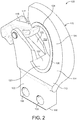
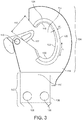
- FIGS 2 and 3 show the hook 100 for the hookloader 10 in detail.
- the hook 100 comprises a shank portion 102 and a hook portion 104.
- the shank portion 102 in this example has a generally cuboidal shape. At a first end 106, the shank portion 102 is configured to be attached to the arm of a hookloader, such as the arm 14 of the hookloader 10. The second end 110 of the shank portion 102 is fixed to the hook portion 104.
- the shank and hook portions 102,104 are integrally formed as one cast item but, in other examples, they may be formed (e.g. milled) integrally from a solid blank or plate, or formed separately and connected together during the hook's manufacture.
- the hook 100 is configured to be removably attached to the arm of a hookloader. This is achieved using two peg-receiving holes 108 which are formed through the shank portion 102 at the first end 106.
- the first end 106 of the shank portion 102 is inserted into a receiving housing 30 (see Figure 1 ) on the distal end of a hookloader arm.
- the receiving housing 30 has holes corresponding to the holes 108 on the shank portion 102. Once the holes of the housing 30 are aligned with the holes 108 on the shank portion 102, locking pegs are inserted into t the holes in order to attach the hook to the arm.
- hooks disclosed herein can be removably attached to a hookloader arm with other configurations.
- the hooks disclosed herein can be configured to be attached to a hookloader arm in a permanent or non-removable manner, for example via welding or being integrally manufactured (e.g. by casting) with the hookloader arm or a portion thereof.
- the hook 100 also comprises a hook portion 104, which comprises a throat 112.
- the throat 112 is an open area which is generally encircled by an arcuately-shaped hook body 114.
- the hook portion 104 has first and second outer surfaces 113,115which face in opposing directions and are generally planar (see also Figure 4 ).
- the throat 112 is for receiving a portion of an item to be lifted, such as a pick-up bar of a container.
- the hook portion comprises a throat opening 116, which is a gap in the hook body 114 through which an item can pass into the throat 112.
- a closure latch 117 is provided to inhibit accidental removal of items in the throat 112.
- the closure latch 117 is pivotable about a pivot 119 from a closed position (as shown in Figure 2 ) in which it blocks the throat opening 116 to inhibit removal of items from the throat 112 and an open position (not shown, but in the clockwise direction in Figure 2 ) in which it received in a recess 123 in the hook body 114 (see Fig.
- the closure latch 117 comprises a combined stopper and counterweight 121 which engages with the hook body 114 in the closed position to prevent the latch from pivoting anti-clockwise out of the throat opening, and also exerts a biasing force to return the latch 117 to the closed position under the natural influence of gravity.
- the throat 112 is generally elliptical in side view, having apexes 118,120 formed at opposing ends.
- a first apex 118 is formed opposite the shank portion 102 and a second apex 120 is formed proximate the shank portion 102.
- the apexes 118,120 are formed by parts of the hook body 114 have a smaller radius of curvature with respect to the rest of the hook body 114 which encircles the throat.
- the hook portion 104 comprises an inner throat surface 122 which is a surface of the hook body 114 facing inwards towards the throat 112.
- the inner throat surface 122 is generally formed about the inner circumference of the throat 112 and is convex across its width (see Figure 6B ) although in other examples, it may be flat across a width thereof. An item to be lifted by the hook 100 will typically predominantly engage the inner throat surface 122.
- the hook portion 104 further comprises a wear indicator 124 which is configured to indicate wear on the hook portion.
- a wear indicator 124 which is configured to indicate wear on the hook portion.
- two wear indicators 124 are provided, one on each of the opposing outer surfaces 113,115 of the hook portion 104.
- the wear indicators 124 are formed around at least a portion of the inner circumference or perimeter of the throat 112 and, in this example, encircle the entire circumference of the throat 112.
- Each wear indicator 124 is formed in this example immediately adjacent the lateral edge of the inner throat surface 122, but it could alternatively be spaced apart from the surface 122.
- a single wear indicator 124 is provided on each opposing side of the throat 112 but in other examples, which will be described below, more than one wear indicator may be provided.
- the wear indicator 124 generally follows the arcuate shape of the throat 112 and the hook body 114.
- the wear indicators 124 take the form of a wear indicator elements 124 which are each raised with respect to the outer surfaces 113,115 of the hook portion 104.
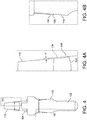
- Figure 4 shows the hook 100 in end view, along the planes of the outer surfaces 113, 115.
- the outer surfaces 113,115 are non-parallel and taper apart towards the shank portion 102.
- the outer surfaces could be parallel, taper in another direction, or be non-planar within the principles of this disclosure.
- the wear indicator element 124 is shown in closer detail.
- the wear indicator element 124 is a raised portion with respect to the outer surface 113 of the hook portion 104.
- the wear indicator element 124 has a substantially constant depth (or height) d from the outer surface 113.
- the wear indicator element 124 is substantially rectangular in cross-section and forms a substantially continuous wear indicator surface 126 which is offset from the outer surface 113 by the depth d.
- the wear indicator surface 126 is also substantially planar.
- the wear indicator surface may be offset from the outer surface of the hook portion by a predetermined distance such that the wear indicator surface has a contour profile substantially identical to a contour profile of the outer surface of the hook portion. Accordingly, if the outer surface 113 were non-planar, then the wear indicator surface could be a raised surface which followed the contours of that non-planar surface.
- Figure 4B shows another detailed view of the hook 100 on the opposing side having outer surface 115.
- the wear indicator element 124 on this side is formed in the same way as the other wear indicator element 124 (i.e. as a raised element having a wear indicator surface 126 which conforms to the outer surface 115).
- the wear indicator elements 124 are formed contiguously with the hook portion 104. In particular, they are integrally cast with the hook 100. However, in other examples, the wear indicator elements could be separate elements which are attached or affixed to the hook portion. As they are integrally cast with the hook 100, the wear indicator elements 124 are formed from the same material as the hook portion 104. However, in other examples, the wear indicator element could be formed from a material having one or more distinguishing characteristics from a material of the hook portion.
- the wear indicators elements 124 are generally elongate, having a length, L, which extends along the curve of the hook portion 104, and a width, W, which is substantially perpendicular to the length L.
- the wear indicators, as described above, have a substantially planar surface 126 meaning they are substantially flat across their width. It will also be appreciated that the wear indicator elements 124 have a substantially constant width along substantially its entire length. Of course, in other examples, the width of the wear indicator may vary along its length.
- a further example of a hook 200 is shown in side view.
- the hook 200 has a shank portion 202 and a hook portion 204 which comprises a throat 212.
- the hook 200 also comprises a wear indicator 224 which, like the wear indicators 124 of the hook 100, encircles the throat 212 and forms a raised wear indicator surface 226.
- the wear indicator 224 has a varying width.
- the wear indicator 224 has a minimum width W 1 proximate the throat apex 218 and a maximum width W 2 proximate the throat apex 220, and gradually increases in width therebetween around the throat 212.
- the width of the wear indicator may vary along its length in different ways. Tailoring the width of the wear indicator to different areas around the throat, which may experience different levels of wear or have different tolerances to wear, may provide improved wear indication.
- the hook portion 304 comprises a primary or inner wear indicator 324 which encircles the throat 312 and a supplementary or outer wear indicator 328 which arranged around and therefore encircles the primary wear indicator 324.
- the supplementary wear indicator 328 follows a substantially similar curve or bend to the primary wear indicator 324.
- the primary and supplementary wear indicators 324,328 are arranged immediately adjacent one another and share a common lateral edge 330.
- the primary wear indicator 324 and the supplementary wear indicator 328 may be formed from materials having different properties so as to provide different wear characteristics.
- the supplementary wear indicator 328 may include one, some, or all of the features described herein with respect to wear indicators, except where mutually exclusive. It should be understood that more than one supplementary wear indicator may be provided.
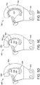
- FIG. 5C a yet further example hook 400 is shown.
- the hook 400 In side view. Some of the common features between the hook 100 and the hook 400 are denoted by reference signs differing by 300.
- the hook 400 like the hook 300 of Figure 5B , the hook 400 comprises both a primary wear indicator 424 and a supplementary wear indicator 428. However, unlike hook 300, on hook 400, the wear indicators 424,428 are laterally spaced apart from one another to provide a spacing gap 432 therebetween. This arrangement may provide improved wear indication in some scenarios.
- a further hook 500 is shown in side view in Figure 5D .
- the hook 500 comprises a first wear indicator 524 which extends around the throat 512 proximate the throat apex 518, and a second, separate wear indicator 528 which extends around the throat 512 proximate the throat apex 520.
- Providing respective wear indicators at the apexes of the throat may provide targeted wear indication in areas which are more prone or susceptible to excessive wear. It should be understood that, more generally, a hook in accordance with this disclosure may comprise more than one wear indicator, each wear indicator arranged in a particular location where wear indication is required.
- FIG. 5E shows a yet further hook 600 in side view.
- a plurality of discrete wear indicators 624 are provided in an array about the throat 612 of the hook 600.
- the spacing between the wear indicators may be varied about the throat 612 (or more generally about the hook portion 624).
- the wear indicators 624 in this example are configured with tighter spacing proximate the throat apexes 618,620 than about the remainder of the throat 612. More generally, providing more closely spaced wear indicators in areas more prone to excessive wear may provide improved wear indication of the hook as a whole.
- the wear indicators 624 in this example are circular or dot-like, other shapes can be envisaged, such as square or triangular indicators.
- the wear indicator 724 does not follow the smooth arcuate shape of the throat 712 and instead has a serpentine shape which encircles the throat 712.
- wear indicators in accordance with this disclosure may take a wide range of shapes, arrangements, and configurations. It should be understood that wear indicators in accordance with this disclosure may include none, one, some, or all of the features of the exemplary wear indicators illustrated, except where mutually exclusive.
- Figures 3 and 5A-F show different exemplary shapes of wear indicators in plan view. Wear indicators may also have differing cross-sectional shapes, which will now be described in more detail with reference to Figures 6-11 . In these Figures, the size of the wear indicators may have been exaggerated in order to provide easier comprehension of the concepts discussed.
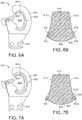
- Figures 6A and 6B show an exemplary hook 800.
- Figure 6A shows the hook in side view
- Figure 6B shows a cross-sectional view through the hook portion 804 on the plane BB in the direction of the arrows.
- the wear indicator 824 of hook 800 is substantially identical to that of wear indicators 124 described in relation to Figures 2 and 3 above.
- a wear indicator 824 is formed immediately adjacent either side of the inner throat surface 822 on the respective outer surface 813,815.
- the wear indicators 824 have a substantially rectangular cross-section when viewed along their length.
- the wear indicators 824 are formed from a material which has one or more different properties to the main hook portion body 814, but it should be understood that in other examples they may be formed from the same material.
- Figures 7A and 7B show an exemplary hook 900.
- Figure 7A shows the hook in side view
- Figure 7B shows a cross-sectional view through the hook portion 904 on the plane BB in the direction of the arrows.
- the hook 900 comprises wear indicators 924 on the outer surfaces 913,915 thereof.
- the wear indicator surface 926 defined by the wear indicator 924 is inclined with respect to its respective outer surface of the hook portion 904 such that the wear indicator element 924 has a decreasing depth along the incline.
- the wear indicator element 924 have a maximum depth proximate the inner throat surface 922, and the minimum depth away from the surface 922.
- the wear indicator elements 924 have a triangular cross-section in this example, with the depth of the wear indicator element 924 relative to the outer surfaces 913,915 approaching zero away from the throat surface 922.
- the minimum depth of the wear indicator elements 924 could be non-zero, such that the wear indicators 924 have a trapezoidal cross section with an inclined wear indicator surface.
- the wear indicator surface 926 is inclined away from the throat 912 such that the wear indicator element 924 has a greatest depth closest to the throat 912.
- the wear indicator surface may be inclined towards the throat such that the element has a greatest depth furthest from the throat.
- the wear indicator surfaces 926 in this example are inclined across a width of the wear indicator surface such that the depth of the wear indicator element varies across a width of the wear indicator element, but it should be understood that the wear indicator surface could alternatively or additionally be inclined in other directions.
- the hook 900 also exemplifies another feature in that the wear indicator element 924 comprises first and second portions 924a, 924b which are formed from materials having different properties.
- this feature does not necessarily need to be implemented in combination with the inclined wear indicator surface 926 and could be utilised with a flat surface, it may provide additional advantages in that, if the materials of portions 924a,b are identifiably different, for example visually different, then a degree of wear may be indicated more clearly. For example, once the outer portion 924b begins to exhibit wear, then this may indicate that the hook is more worn than when just inner portion 924a is worn. Of course, more than two portions having different materials could be provided to give a yet further more precise indication of the degree of wear.
- Figures 8A and 8B show an exemplary hook 1000.
- Figure 8A shows the hook in side view
- Figure 8B shows a cross-sectional view through the hook portion 1004 on the plane BB in the direction of the arrows.
- the hook 1000 has wear indicator elements 1024 has flat wear indicator surfaces 1026 and two portions 1024a and 1024b formed from different materials.
- the different portions 1024a,b are stacked in the depth direction of the wear indicator element 1024, meaning that the inner portion 1024b is entirely encapsulated by the outer portion 1024a. If the materials of portions 924a,b are identifiably different, for example visually different, then a degree of wear may be indicated more clearly by this arrangement.
- the wear indicators 1024 of hook 100 could have more than two portions having different materials to give a yet further more precise indication of the degree of wear.
- Figures 9A and 9B show an exemplary hook 1100.
- Figure 9A shows the hook in side view
- Figure 9B shows a cross-sectional view through the hook portion 1104 on the plane BB in the direction of the arrows.
- the wear indicator surfaces 1126 of the wear indicator elements 1124 are convex.
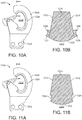
- Figures 10A and 10B show an exemplary hook 1200.
- Figure 10A shows the hook in side view
- Figure 10B shows a cross-sectional view through the hook portion 1204 on the plane BB in the direction of the arrows.
- the wear indicator surfaces 1226 of the wear indicator elements 1224 are concave.
- Providing convex or concave wear indicator surfaces according to the examples of Figures 9 and 10 may provide more detailed insight into how even or uneven wear is occurring on a hook.
- Figures 11A and 11B show an exemplary hook 1300.
- Figure 11A shows the hook in side view
- Figure 11B shows a cross-sectional view through the hook portion 1304 on the plane BB in the direction of the arrows.
- the wear indicator 1324 is a wear indicator recess 1324 which is substantially recessed with respect to the respective outer surface 1313,1315 of the hook portion 1304.
- a wear indicator recess may be formed as a groove in the outer surface of the hook portion spaced apart from the inner throat surface.
- a wear indicator recess may indicate wear as the depth of the recess may decrease as increasing wear occurs.
- wear indicators may be provided having a selection of multiple features disclosed in the different examples described above, e.g. in a 'mix-and-match' manner.
- a wear indicator formed on the hook portion configured to indicate wear on the hook portion.
- the various wear indicators disclosed may generally provide an additional dedicated sacrificial element which may be worn during the hook's use and which can thereby indicate an amount of wear which has occurred to the hook.
- Some wear indicators disclosed could be configured to receive wear and indicate wear on the hook without significantly altering the structural properties or loading capacity of the hook itself. Accordingly, it will be appreciated that the wear indicators disclosed herein may aid users of hookloaders in more accurately assessing the wear which occurs on hooks, thereby indicating more clearly when a hook may need to be replaced or repaired. This may improve the safety or reliability of hookloaders, for example.
Landscapes
- Engineering & Computer Science (AREA)
- Mechanical Engineering (AREA)
- General Engineering & Computer Science (AREA)
- Transportation (AREA)
- Hooks, Suction Cups, And Attachment By Adhesive Means (AREA)
- Load-Engaging Elements For Cranes (AREA)
Priority Applications (3)
| Application Number | Priority Date | Filing Date | Title |
|---|---|---|---|
| EP18210855.5A EP3663591B1 (de) | 2018-12-06 | 2018-12-06 | Haken für einen hakenlader |
| CN201922155664.6U CN212024551U (zh) | 2018-12-06 | 2019-12-05 | 用于吊钩装载机的吊钩以及包括其的吊钩装载机 |
| CN201911232510.0A CN111285245B (zh) | 2018-12-06 | 2019-12-05 | 吊钩装载机的吊钩 |
Applications Claiming Priority (1)
| Application Number | Priority Date | Filing Date | Title |
|---|---|---|---|
| EP18210855.5A EP3663591B1 (de) | 2018-12-06 | 2018-12-06 | Haken für einen hakenlader |
Publications (2)
| Publication Number | Publication Date |
|---|---|
| EP3663591A1 true EP3663591A1 (de) | 2020-06-10 |
| EP3663591B1 EP3663591B1 (de) | 2021-10-06 |
Family
ID=64650303
Family Applications (1)
| Application Number | Title | Priority Date | Filing Date |
|---|---|---|---|
| EP18210855.5A Active EP3663591B1 (de) | 2018-12-06 | 2018-12-06 | Haken für einen hakenlader |
Country Status (2)
| Country | Link |
|---|---|
| EP (1) | EP3663591B1 (de) |
| CN (2) | CN212024551U (de) |
Cited By (1)
| Publication number | Priority date | Publication date | Assignee | Title |
|---|---|---|---|---|
| CN114619938A (zh) * | 2020-12-09 | 2022-06-14 | 海沃控股有限公司 | 拉臂车及其操作方法 |
Families Citing this family (3)
| Publication number | Priority date | Publication date | Assignee | Title |
|---|---|---|---|---|
| EP3663591B1 (de) * | 2018-12-06 | 2021-10-06 | Hyva Holding BV | Haken für einen hakenlader |
| DE102021112071A1 (de) * | 2021-05-10 | 2022-11-10 | Zf Cv Systems Global Gmbh | Verfahren zum Überwachen einer Kupplungsverbindung zwischen Teilfahrzeugen eines Fahrzeug-Gespanns sowie Fahrzeug-Gespann |
| CN115520679B (zh) * | 2021-06-25 | 2025-10-14 | 顺丰科技有限公司 | 卸货装置 |
Citations (2)
| Publication number | Priority date | Publication date | Assignee | Title |
|---|---|---|---|---|
| DE2903462A1 (de) * | 1979-01-30 | 1980-08-07 | Meiller Fahrzeuge | Abrollkipper |
| US5542807A (en) * | 1994-05-03 | 1996-08-06 | Galbreath Incorporated | Vehicle mounted, variable length hook hoist |
Family Cites Families (11)
| Publication number | Priority date | Publication date | Assignee | Title |
|---|---|---|---|---|
| CN203781645U (zh) * | 2014-04-30 | 2014-08-20 | 宁波盛发铜业有限公司 | 行车吊钩 |
| CN204384710U (zh) * | 2014-11-26 | 2015-06-10 | 惠州市联电电线电缆有限公司 | 一种用于吊装电线的机械手 |
| CN205011286U (zh) * | 2015-10-15 | 2016-02-03 | 金华送变电工程有限公司 | 一种导线提升装置 |
| CN105480852A (zh) * | 2015-12-30 | 2016-04-13 | 安徽省超盛起重机械有限公司 | 一种起重机吊钩结构 |
| CN106395613B (zh) * | 2016-11-30 | 2018-02-06 | 国家电网公司 | 一种导线吊钩 |
| CN206751189U (zh) * | 2017-05-16 | 2017-12-15 | 陈重 | 一种起重机用使用安全的吊钩组 |
| CN207293934U (zh) * | 2017-05-31 | 2018-05-01 | 河南宝起华东起重机有限公司 | 一种起重机用简便防脱吊钩 |
| CN108083099A (zh) * | 2017-12-21 | 2018-05-29 | 合肥市春华起重机械有限公司 | 一种防脱落性好的焊接吊钩 |
| CN208071161U (zh) * | 2018-01-31 | 2018-11-09 | 高进 | 一种民用小型吊机 |
| CN207877107U (zh) * | 2018-02-02 | 2018-09-18 | 常州凯润科技有限公司 | 防磨损可更换拖钩 |
| EP3663591B1 (de) * | 2018-12-06 | 2021-10-06 | Hyva Holding BV | Haken für einen hakenlader |
-
2018
- 2018-12-06 EP EP18210855.5A patent/EP3663591B1/de active Active
-
2019
- 2019-12-05 CN CN201922155664.6U patent/CN212024551U/zh active Active
- 2019-12-05 CN CN201911232510.0A patent/CN111285245B/zh active Active
Patent Citations (2)
| Publication number | Priority date | Publication date | Assignee | Title |
|---|---|---|---|---|
| DE2903462A1 (de) * | 1979-01-30 | 1980-08-07 | Meiller Fahrzeuge | Abrollkipper |
| US5542807A (en) * | 1994-05-03 | 1996-08-06 | Galbreath Incorporated | Vehicle mounted, variable length hook hoist |
Cited By (2)
| Publication number | Priority date | Publication date | Assignee | Title |
|---|---|---|---|---|
| CN114619938A (zh) * | 2020-12-09 | 2022-06-14 | 海沃控股有限公司 | 拉臂车及其操作方法 |
| EP4011698A1 (de) * | 2020-12-09 | 2022-06-15 | Hyva Holding BV | Hakenladegerät und verfahren zum betrieb desselben |
Also Published As
| Publication number | Publication date |
|---|---|
| CN111285245A (zh) | 2020-06-16 |
| CN111285245B (zh) | 2025-12-23 |
| EP3663591B1 (de) | 2021-10-06 |
| CN212024551U (zh) | 2020-11-27 |
Similar Documents
| Publication | Publication Date | Title |
|---|---|---|
| EP3663591B1 (de) | Haken für einen hakenlader | |
| US8967287B2 (en) | Ripper tip for a ripper shank assembly | |
| CN107075841B (zh) | 用于工具的磨耗构件 | |
| EP3135828A1 (de) | Aufreisserschaftanordnung | |
| CN104603370A (zh) | 铲斗斗角、掘地工具及其相互机械附接 | |
| US9758947B2 (en) | Mounting base for wear member | |
| JP7504107B2 (ja) | 土工機器用摩耗アセンブリー | |
| EP2607290B1 (de) | Wippe für Gehänge mit Anzeigeanordnung | |
| US8887826B2 (en) | Shank protector for a ripper shank assembly | |
| GB2599601A (en) | Chain conveyor link | |
| EP3421272B1 (de) | Anhängerkupplung mit sensor zur verschleissdetektion | |
| ES2971327T3 (es) | Un elemento de forro de transición para un forro para la carrocería de un camión de transporte | |
| US11808016B2 (en) | Bucket lip for earth moving machines | |
| EP2362024A2 (de) | Schnellkupplung für ein Grab- und Ladewerkzeug | |
| US20160244943A1 (en) | Safety lifting system for a mechanical excavator | |
| EP3642077B1 (de) | Verkleidungselement für eine verschleissbeständige verkleidung eines lastwagenaufbaus und verfahren zur herstellung eines verkleidungselements | |
| NO20240952A1 (de) | ||
| AU2025259980A1 (en) | Replaceable wear plate | |
| BR112021010769A2 (pt) | Uma caçamba para uma máquina de terraplanagem ou de manipulação de materiais |
Legal Events
| Date | Code | Title | Description |
|---|---|---|---|
| PUAI | Public reference made under article 153(3) epc to a published international application that has entered the european phase |
Free format text: ORIGINAL CODE: 0009012 |
|
| STAA | Information on the status of an ep patent application or granted ep patent |
Free format text: STATUS: THE APPLICATION HAS BEEN PUBLISHED |
|
| AK | Designated contracting states |
Kind code of ref document: A1 Designated state(s): AL AT BE BG CH CY CZ DE DK EE ES FI FR GB GR HR HU IE IS IT LI LT LU LV MC MK MT NL NO PL PT RO RS SE SI SK SM TR |
|
| AX | Request for extension of the european patent |
Extension state: BA ME |
|
| STAA | Information on the status of an ep patent application or granted ep patent |
Free format text: STATUS: REQUEST FOR EXAMINATION WAS MADE |
|
| 17P | Request for examination filed |
Effective date: 20201209 |
|
| RBV | Designated contracting states (corrected) |
Designated state(s): AL AT BE BG CH CY CZ DE DK EE ES FI FR GB GR HR HU IE IS IT LI LT LU LV MC MK MT NL NO PL PT RO RS SE SI SK SM TR |
|
| GRAP | Despatch of communication of intention to grant a patent |
Free format text: ORIGINAL CODE: EPIDOSNIGR1 |
|
| STAA | Information on the status of an ep patent application or granted ep patent |
Free format text: STATUS: GRANT OF PATENT IS INTENDED |
|
| RIC1 | Information provided on ipc code assigned before grant |
Ipc: F16B 1/00 20060101AFI20210407BHEP Ipc: B60P 1/64 20060101ALI20210407BHEP Ipc: F16B 45/02 20060101ALI20210407BHEP |
|
| INTG | Intention to grant announced |
Effective date: 20210430 |
|
| GRAS | Grant fee paid |
Free format text: ORIGINAL CODE: EPIDOSNIGR3 |
|
| GRAA | (expected) grant |
Free format text: ORIGINAL CODE: 0009210 |
|
| STAA | Information on the status of an ep patent application or granted ep patent |
Free format text: STATUS: THE PATENT HAS BEEN GRANTED |
|
| AK | Designated contracting states |
Kind code of ref document: B1 Designated state(s): AL AT BE BG CH CY CZ DE DK EE ES FI FR GB GR HR HU IE IS IT LI LT LU LV MC MK MT NL NO PL PT RO RS SE SI SK SM TR |
|
| REG | Reference to a national code |
Ref country code: GB Ref legal event code: FG4D |
|
| REG | Reference to a national code |
Ref country code: CH Ref legal event code: EP Ref country code: AT Ref legal event code: REF Ref document number: 1436479 Country of ref document: AT Kind code of ref document: T Effective date: 20211015 |
|
| REG | Reference to a national code |
Ref country code: IE Ref legal event code: FG4D |
|
| REG | Reference to a national code |
Ref country code: DE Ref legal event code: R096 Ref document number: 602018024582 Country of ref document: DE |
|
| REG | Reference to a national code |
Ref country code: FI Ref legal event code: FGE |
|
| REG | Reference to a national code |
Ref country code: LT Ref legal event code: MG9D |
|
| REG | Reference to a national code |
Ref country code: NL Ref legal event code: MP Effective date: 20211006 |
|
| PG25 | Lapsed in a contracting state [announced via postgrant information from national office to epo] |
Ref country code: RS Free format text: LAPSE BECAUSE OF FAILURE TO SUBMIT A TRANSLATION OF THE DESCRIPTION OR TO PAY THE FEE WITHIN THE PRESCRIBED TIME-LIMIT Effective date: 20211006 Ref country code: LT Free format text: LAPSE BECAUSE OF FAILURE TO SUBMIT A TRANSLATION OF THE DESCRIPTION OR TO PAY THE FEE WITHIN THE PRESCRIBED TIME-LIMIT Effective date: 20211006 Ref country code: BG Free format text: LAPSE BECAUSE OF FAILURE TO SUBMIT A TRANSLATION OF THE DESCRIPTION OR TO PAY THE FEE WITHIN THE PRESCRIBED TIME-LIMIT Effective date: 20220106 |
|
| PG25 | Lapsed in a contracting state [announced via postgrant information from national office to epo] |
Ref country code: IS Free format text: LAPSE BECAUSE OF FAILURE TO SUBMIT A TRANSLATION OF THE DESCRIPTION OR TO PAY THE FEE WITHIN THE PRESCRIBED TIME-LIMIT Effective date: 20220206 Ref country code: SE Free format text: LAPSE BECAUSE OF FAILURE TO SUBMIT A TRANSLATION OF THE DESCRIPTION OR TO PAY THE FEE WITHIN THE PRESCRIBED TIME-LIMIT Effective date: 20211006 Ref country code: PT Free format text: LAPSE BECAUSE OF FAILURE TO SUBMIT A TRANSLATION OF THE DESCRIPTION OR TO PAY THE FEE WITHIN THE PRESCRIBED TIME-LIMIT Effective date: 20220207 Ref country code: PL Free format text: LAPSE BECAUSE OF FAILURE TO SUBMIT A TRANSLATION OF THE DESCRIPTION OR TO PAY THE FEE WITHIN THE PRESCRIBED TIME-LIMIT Effective date: 20211006 Ref country code: NO Free format text: LAPSE BECAUSE OF FAILURE TO SUBMIT A TRANSLATION OF THE DESCRIPTION OR TO PAY THE FEE WITHIN THE PRESCRIBED TIME-LIMIT Effective date: 20220106 Ref country code: NL Free format text: LAPSE BECAUSE OF FAILURE TO SUBMIT A TRANSLATION OF THE DESCRIPTION OR TO PAY THE FEE WITHIN THE PRESCRIBED TIME-LIMIT Effective date: 20211006 Ref country code: LV Free format text: LAPSE BECAUSE OF FAILURE TO SUBMIT A TRANSLATION OF THE DESCRIPTION OR TO PAY THE FEE WITHIN THE PRESCRIBED TIME-LIMIT Effective date: 20211006 Ref country code: HR Free format text: LAPSE BECAUSE OF FAILURE TO SUBMIT A TRANSLATION OF THE DESCRIPTION OR TO PAY THE FEE WITHIN THE PRESCRIBED TIME-LIMIT Effective date: 20211006 Ref country code: GR Free format text: LAPSE BECAUSE OF FAILURE TO SUBMIT A TRANSLATION OF THE DESCRIPTION OR TO PAY THE FEE WITHIN THE PRESCRIBED TIME-LIMIT Effective date: 20220107 Ref country code: ES Free format text: LAPSE BECAUSE OF FAILURE TO SUBMIT A TRANSLATION OF THE DESCRIPTION OR TO PAY THE FEE WITHIN THE PRESCRIBED TIME-LIMIT Effective date: 20211006 |
|
| REG | Reference to a national code |
Ref country code: DE Ref legal event code: R097 Ref document number: 602018024582 Country of ref document: DE |
|
| PG25 | Lapsed in a contracting state [announced via postgrant information from national office to epo] |
Ref country code: SM Free format text: LAPSE BECAUSE OF FAILURE TO SUBMIT A TRANSLATION OF THE DESCRIPTION OR TO PAY THE FEE WITHIN THE PRESCRIBED TIME-LIMIT Effective date: 20211006 Ref country code: SK Free format text: LAPSE BECAUSE OF FAILURE TO SUBMIT A TRANSLATION OF THE DESCRIPTION OR TO PAY THE FEE WITHIN THE PRESCRIBED TIME-LIMIT Effective date: 20211006 Ref country code: RO Free format text: LAPSE BECAUSE OF FAILURE TO SUBMIT A TRANSLATION OF THE DESCRIPTION OR TO PAY THE FEE WITHIN THE PRESCRIBED TIME-LIMIT Effective date: 20211006 Ref country code: MC Free format text: LAPSE BECAUSE OF FAILURE TO SUBMIT A TRANSLATION OF THE DESCRIPTION OR TO PAY THE FEE WITHIN THE PRESCRIBED TIME-LIMIT Effective date: 20211006 Ref country code: EE Free format text: LAPSE BECAUSE OF FAILURE TO SUBMIT A TRANSLATION OF THE DESCRIPTION OR TO PAY THE FEE WITHIN THE PRESCRIBED TIME-LIMIT Effective date: 20211006 Ref country code: DK Free format text: LAPSE BECAUSE OF FAILURE TO SUBMIT A TRANSLATION OF THE DESCRIPTION OR TO PAY THE FEE WITHIN THE PRESCRIBED TIME-LIMIT Effective date: 20211006 Ref country code: CZ Free format text: LAPSE BECAUSE OF FAILURE TO SUBMIT A TRANSLATION OF THE DESCRIPTION OR TO PAY THE FEE WITHIN THE PRESCRIBED TIME-LIMIT Effective date: 20211006 |
|
| REG | Reference to a national code |
Ref country code: CH Ref legal event code: PL |
|
| PLBE | No opposition filed within time limit |
Free format text: ORIGINAL CODE: 0009261 |
|
| STAA | Information on the status of an ep patent application or granted ep patent |
Free format text: STATUS: NO OPPOSITION FILED WITHIN TIME LIMIT |
|
| 26N | No opposition filed |
Effective date: 20220707 |
|
| REG | Reference to a national code |
Ref country code: BE Ref legal event code: MM Effective date: 20211231 |
|
| PG25 | Lapsed in a contracting state [announced via postgrant information from national office to epo] |
Ref country code: LU Free format text: LAPSE BECAUSE OF NON-PAYMENT OF DUE FEES Effective date: 20211206 Ref country code: IE Free format text: LAPSE BECAUSE OF NON-PAYMENT OF DUE FEES Effective date: 20211206 Ref country code: AL Free format text: LAPSE BECAUSE OF FAILURE TO SUBMIT A TRANSLATION OF THE DESCRIPTION OR TO PAY THE FEE WITHIN THE PRESCRIBED TIME-LIMIT Effective date: 20211006 |
|
| PG25 | Lapsed in a contracting state [announced via postgrant information from national office to epo] |
Ref country code: SI Free format text: LAPSE BECAUSE OF FAILURE TO SUBMIT A TRANSLATION OF THE DESCRIPTION OR TO PAY THE FEE WITHIN THE PRESCRIBED TIME-LIMIT Effective date: 20211006 Ref country code: BE Free format text: LAPSE BECAUSE OF NON-PAYMENT OF DUE FEES Effective date: 20211231 |
|
| PG25 | Lapsed in a contracting state [announced via postgrant information from national office to epo] |
Ref country code: LI Free format text: LAPSE BECAUSE OF NON-PAYMENT OF DUE FEES Effective date: 20211231 Ref country code: CH Free format text: LAPSE BECAUSE OF NON-PAYMENT OF DUE FEES Effective date: 20211231 |
|
| REG | Reference to a national code |
Ref country code: AT Ref legal event code: UEP Ref document number: 1436479 Country of ref document: AT Kind code of ref document: T Effective date: 20211006 |
|
| PG25 | Lapsed in a contracting state [announced via postgrant information from national office to epo] |
Ref country code: CY Free format text: LAPSE BECAUSE OF FAILURE TO SUBMIT A TRANSLATION OF THE DESCRIPTION OR TO PAY THE FEE WITHIN THE PRESCRIBED TIME-LIMIT Effective date: 20211006 |
|
| P01 | Opt-out of the competence of the unified patent court (upc) registered |
Effective date: 20230530 |
|
| PG25 | Lapsed in a contracting state [announced via postgrant information from national office to epo] |
Ref country code: HU Free format text: LAPSE BECAUSE OF FAILURE TO SUBMIT A TRANSLATION OF THE DESCRIPTION OR TO PAY THE FEE WITHIN THE PRESCRIBED TIME-LIMIT; INVALID AB INITIO Effective date: 20181206 |
|
| PG25 | Lapsed in a contracting state [announced via postgrant information from national office to epo] |
Ref country code: MK Free format text: LAPSE BECAUSE OF FAILURE TO SUBMIT A TRANSLATION OF THE DESCRIPTION OR TO PAY THE FEE WITHIN THE PRESCRIBED TIME-LIMIT Effective date: 20211006 |
|
| PG25 | Lapsed in a contracting state [announced via postgrant information from national office to epo] |
Ref country code: MT Free format text: LAPSE BECAUSE OF FAILURE TO SUBMIT A TRANSLATION OF THE DESCRIPTION OR TO PAY THE FEE WITHIN THE PRESCRIBED TIME-LIMIT Effective date: 20211006 |
|
| PGFP | Annual fee paid to national office [announced via postgrant information from national office to epo] |
Ref country code: FI Payment date: 20241209 Year of fee payment: 7 |
|
| PGFP | Annual fee paid to national office [announced via postgrant information from national office to epo] |
Ref country code: AT Payment date: 20241206 Year of fee payment: 7 |
|
| PGFP | Annual fee paid to national office [announced via postgrant information from national office to epo] |
Ref country code: IT Payment date: 20241213 Year of fee payment: 7 |
|
| PG25 | Lapsed in a contracting state [announced via postgrant information from national office to epo] |
Ref country code: TR Free format text: LAPSE BECAUSE OF FAILURE TO SUBMIT A TRANSLATION OF THE DESCRIPTION OR TO PAY THE FEE WITHIN THE PRESCRIBED TIME-LIMIT Effective date: 20211006 |
|
| PGFP | Annual fee paid to national office [announced via postgrant information from national office to epo] |
Ref country code: DE Payment date: 20251215 Year of fee payment: 8 |
|
| PGFP | Annual fee paid to national office [announced via postgrant information from national office to epo] |
Ref country code: GB Payment date: 20251216 Year of fee payment: 8 |
|
| PGFP | Annual fee paid to national office [announced via postgrant information from national office to epo] |
Ref country code: FR Payment date: 20251118 Year of fee payment: 8 |