EP3663569B1 - Vorrichtung zum entladen eines schalters - Google Patents
Vorrichtung zum entladen eines schalters Download PDFInfo
- Publication number
- EP3663569B1 EP3663569B1 EP19213785.9A EP19213785A EP3663569B1 EP 3663569 B1 EP3663569 B1 EP 3663569B1 EP 19213785 A EP19213785 A EP 19213785A EP 3663569 B1 EP3663569 B1 EP 3663569B1
- Authority
- EP
- European Patent Office
- Prior art keywords
- needle
- injector
- discharge device
- detection circuit
- transistor
- Prior art date
- Legal status (The legal status is an assumption and is not a legal conclusion. Google has not performed a legal analysis and makes no representation as to the accuracy of the status listed.)
- Active
Links
Images


Classifications
-
- F—MECHANICAL ENGINEERING; LIGHTING; HEATING; WEAPONS; BLASTING
- F02—COMBUSTION ENGINES; HOT-GAS OR COMBUSTION-PRODUCT ENGINE PLANTS
- F02D—CONTROLLING COMBUSTION ENGINES
- F02D41/00—Electrical control of supply of combustible mixture or its constituents
- F02D41/20—Output circuits, e.g. for controlling currents in command coils
-
- F—MECHANICAL ENGINEERING; LIGHTING; HEATING; WEAPONS; BLASTING
- F02—COMBUSTION ENGINES; HOT-GAS OR COMBUSTION-PRODUCT ENGINE PLANTS
- F02D—CONTROLLING COMBUSTION ENGINES
- F02D41/00—Electrical control of supply of combustible mixture or its constituents
- F02D41/20—Output circuits, e.g. for controlling currents in command coils
- F02D2041/202—Output circuits, e.g. for controlling currents in command coils characterised by the control of the circuit
- F02D2041/2051—Output circuits, e.g. for controlling currents in command coils characterised by the control of the circuit using voltage control
-
- F—MECHANICAL ENGINEERING; LIGHTING; HEATING; WEAPONS; BLASTING
- F02—COMBUSTION ENGINES; HOT-GAS OR COMBUSTION-PRODUCT ENGINE PLANTS
- F02D—CONTROLLING COMBUSTION ENGINES
- F02D41/00—Electrical control of supply of combustible mixture or its constituents
- F02D41/20—Output circuits, e.g. for controlling currents in command coils
- F02D2041/202—Output circuits, e.g. for controlling currents in command coils characterised by the control of the circuit
- F02D2041/2055—Output circuits, e.g. for controlling currents in command coils characterised by the control of the circuit with means for determining actual opening or closing time
-
- F—MECHANICAL ENGINEERING; LIGHTING; HEATING; WEAPONS; BLASTING
- F02—COMBUSTION ENGINES; HOT-GAS OR COMBUSTION-PRODUCT ENGINE PLANTS
- F02D—CONTROLLING COMBUSTION ENGINES
- F02D41/00—Electrical control of supply of combustible mixture or its constituents
- F02D41/20—Output circuits, e.g. for controlling currents in command coils
- F02D2041/2068—Output circuits, e.g. for controlling currents in command coils characterised by the circuit design or special circuit elements
- F02D2041/2075—Type of transistors or particular use thereof
-
- F—MECHANICAL ENGINEERING; LIGHTING; HEATING; WEAPONS; BLASTING
- F02—COMBUSTION ENGINES; HOT-GAS OR COMBUSTION-PRODUCT ENGINE PLANTS
- F02M—SUPPLYING COMBUSTION ENGINES IN GENERAL WITH COMBUSTIBLE MIXTURES OR CONSTITUENTS THEREOF
- F02M65/00—Testing fuel-injection apparatus, e.g. testing injection timing ; Cleaning of fuel-injection apparatus
- F02M65/005—Measuring or detecting injection-valve lift, e.g. to determine injection timing
Definitions
- the present invention relates to a device for discharging a high voltage electrical switch arranged in a circuit for detecting the positioning of a needle of a fuel injector for an internal combustion engine.
- a fuel injector conventionally comprises a needle controlled in opening and closing as a function of the pressure prevailing in a control chamber, which pressure is a function of the position of a control solenoid valve. These small movements are carried out at high speed. The regularly increased performance now requires feedback on the actual position of the needle for optimal control.
- Devices are known in which a sensor is arranged on the injector, or even an injector in which certain surfaces of the components of the body are provided with resistive coatings so that a measurement of electrical resistance can be carried out between two elements of the injector .
- a closed loop strategy is implemented in which a control unit receives a signal relating to the position of the injector needle.
- fuel Several electrical switch devices have been designed using the needle tip and complementary bearing face to make electrical contact as described in GB2554916A .
- the “ICL” electrical switch is based on the fact that the electrical switching circuit is in series with pull-up resistors, supplied by a direct voltage. Injector resistance is related to the position of the injector needle and generally changes depending on the position of the needle and the physical contact between the needle and a nozzle body or with an assembly of injector control valve.
- the electrical switching circuit is a needle positioning detection circuit. In order to improve the accuracy and stability of the electrical switch reading, a higher voltage is applied across the circuit terminals needle positioning detection, which gives better results.
- the disadvantage of this solution is the electric discharge when changing from a high voltage level to a low voltage level corresponding to the change from the open position to the closed position of the electrical switch called ICL.
- Electrical energy is dissipated at the conical end of the needle and the complementary conical seat of an injector body causing damage to the surfaces of the needle or nozzle body.
- the surface coating is partially destroyed either on the conical end of the needle or on the conical seat of the injector body. This is called spark erosion caused by the needle position detection circuit switch closing when the injection is completed.
- the object of the invention is to solve the problems mentioned above.
- the invention is described relating to a discharge device 10 of a high voltage electrical switch 12 also called ICL arranged in the positioning detection circuit 14 of a needle 16 of a fuel injector 18 for a combustion engine internal.
- the injector 18 is a diesel injector although the invention can be fully transposed to a gasoline injector or any other fuel or any other liquid form. The description will detail the elements of the invention and will remain more succinct and general with regard to the surrounding elements.
- the fuel injector 18 forming part of an injection system of an internal combustion engine (not shown).
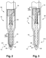
- the injector 18 is shown in axial section along a longitudinal axis X.
- the injector 18 comprises a control valve assembly 20 held tight by an injector nut (not shown) between an actuator body 22 and a nozzle assembly 24.
- the injector 18 extends along the longitudinal axis the control valve assembly 20 comprises a valve body 27, an actuator 28 arranged in the actuator body 22.
- the needle 16 is axially slidably arranged in a bore 30 of the nozzle body.
- the injector 18 further comprises the positioning detection circuit 14 of the needle 16, also commonly called ICL.
- the positioning detection circuit 14 of the needle 16 is an electrical circuit.
- the electrical measurement consists of measuring the potential difference between the mass M and the voltage source Vicl.
- the maximum voltage value is the value of the voltage source.
- the positioning detection circuit 14 of the needle 16 makes it possible to carry out an electrical measurement between a lug of the connector (not shown) and the mass M at which the nozzle body 16, the actuator body 22 and the injector nut (not shown).
- the positioning detection circuit 14 comprises an electrical connection which extends from the terminal (not shown) to a needle spring 32, then the needle spring 32 to it -same, then the needle 16 to a first end 34 of the needle and finally the nozzle body 26 from a seat 36 of the nozzle body to the mass M.
- the positioning detection circuit 14 comprises an electrical connection which extends from the lug (not shown) to the needle spring 32, then the spring 32 itself, then the needle 14 to a second end 38 of the needle, and finally the valve body 27 from a lower face of the valve body 27 which is in contact with the second end 38 of the needle to the mass Mr.
- An injection cycle includes a main opening during which the needle 16 travels the entire movement between the two extreme positions.
- the discharge device 10 is arranged in the positioning detection circuit 12 of the needle 16 of the fuel injector 18.
- the discharge device 10 and the positioning detection circuit 14 of the needle 16 in the injector 18 are arranged in a control unit 40.
- the discharge device 10 comprises a transistor 42 whose collector path C - emitter E is connected in series between the voltage source Vicl and the ground M, the transistor 42 being controlled at its base B by a logic signal coming from of the control unit 40.
- the discharge device 10 is there to avoid electroerosion which occurs either on the first end 34 of the needle or on the seat 36 of the nozzle body or on these two parts.
- the discharge device 10 serves to evacuate the electrons when closing the switch 12 of the positioning detection circuit 14 towards the ground M passing through the transistor 42.
- the electrons present in the positioning detection circuit 14 are stored in the injector 18 and come from a parasitic capacitor corresponding to an insulating surface of the upper guide 43, to an insulating surface of the lower guide 46 and the electrical wires connected to the voltage source Vicl and to the mass M.
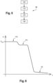
- the switch 12 of the positioning detection circuit 14 is in the open position PO, that is to say that the voltage in the electrical circuit is at a maximum voltage corresponding to the value of the voltage source Vicl.
- the electrical switch 12 is in the closed position PF, that is to say that the voltage in the electrical circuit is at the minimum value, that is to say 0 Volts which is the value of the mass M.
- the voltage curve of the positioning detection circuit 14 makes it possible to know the closed position PF and the open position PO of the needle 16 of the injector 18.
- the passage of the open position PO that is to say a maximum voltage corresponding to the voltage Vicl in the positioning detection circuit 14
- the closed position PF of the injector 18 corresponds to the electrical discharge created by the passage from the maximum voltage to the minimum voltage.
- the voltage curve also presents a Pre-drop PC which is an electrical pre-discharge created by the end of the injection of fuel from the injector 18.
- the Pre-drop PC is the moment when the needle 16 is detaches from the seat 36 of the nozzle body with the presence of a fuel film arranged between the needle 16 and the seat 36. The fuel film at this time creates an electric field.
- the discharge device 10 comprises the transistor 42 whose collector - emitter path is connected in series between the voltage source Vicl and the ground M, the transistor 42 being controlled by a logic signal coming from the control unit 40, a Zener diode DZ1 so as to maintain a minimum voltage in the injector 18, that is to say a voltage of the order of 1.5 Volt.
- the Zener diode DZ1 avoids a clear short circuit, which allows part of the electrical signal to be retained during closing and thus allows the PC Pre-drop described previously to be detected.
- the PC Pre-drop is an electrical pre-discharge created by the end of the fuel injection of the injector 18.
- the second embodiment makes it possible to identify with greater probability the PC Pre-drop of voltage which occurs. produced at the end of the injection and avoids the risk of confusion with a spurious event.
- the injector 18 is provided with a fuel circulation circuit which makes it possible to bring high pressure fuel via a high pressure circuit from an inlet orifice (not shown) arranged in an upper part of the injector 18 up to 'to the injection holes arranged in a lower part of the nozzle body 26 the injector 18.
- injector 18 As described in the figures 1 And 3 , when the actuator 28 is electrically energized, it attracts a magnetic armature and a valve stem which are fixed together, which opens a discharge channel and allows fuel trapped in a control chamber to discharge to a low pressure circuit (not shown). Then the pressure decreases in the control chamber and the needle 16 moves in the bore 30 of the nozzle body 26 towards the open position PO in which the first end 34 of the needle 16 moves away from the seat 36 of the body nozzle 26. Consequently, the second end 38 of the needle 16 comes into contact with a lower face of the valve body 27.
- the magnetic armature and control rod assembly When the actuator 28 is not powered, the magnetic armature and control rod assembly is pushed back by a valve spring towards a position which prevents fuel from flowing towards the discharge channel which is closed, which retains the high pressure fuel arriving there. Then the pressure in the control chamber rises and the needle 16 is pushed downwards by the spring 32 of the needle 16 and the first end 34 of the needle 16 is in contact with the seat 36 of the nozzle body 26 and the second end 38 of the needle 16 is distant from the lower face of the valve body 27.
Landscapes
- Engineering & Computer Science (AREA)
- Chemical & Material Sciences (AREA)
- Combustion & Propulsion (AREA)
- Mechanical Engineering (AREA)
- General Engineering & Computer Science (AREA)
- Fuel-Injection Apparatus (AREA)
- Electrical Control Of Air Or Fuel Supplied To Internal-Combustion Engine (AREA)
Claims (2)
- Entladevorrichtung (10) für den Übergang eines Schalters (12) aus dem offenen in den geschlossenen Zustand, wobei die Entladevorrichtung (10) dazu dient, die Elektronen beim Schließen des Schalters (12) einer Positionserfassungsschaltung (14) über einen Transistor (42) zur Masse (M) abzuleiten, und die Entladevorrichtung (10) in der Positionserfassungsschaltung (14) einer Nadel (16) eines Kraftstoffeinspritzventils (18) für einen Verbrennungsmotor angeordnet ist, wobei sich die Positionserfassungsschaltung (14) in einer Steuerungseinheit (40) eines Einspritzers (18) befindet und die elektrische Messung der Potenzialdifferenz zwischen der Masse (M) und einer Spannungsquelle (Vicl) ermöglicht, welche Messung eine offene oder geschlossene Endstellung der Nadel anzeigt,
wobei die Entladevorrichtung (10) einen Transistor (42) umfasst, dessen Kollektor-Emitter-Pfad zwischen der Spannungsquelle (Vicl) und der Masse (M) in Reihe geschaltet ist, wobei der Transistor (42) durch ein logisches, von der Steuereinheit (40) kommendes Signal gesteuert wird. - Entladevorrichtung (10) nach dem vorstehenden Anspruch, bei der die Entladevorrichtung (10) ferner eine Z-Diode (DZ1) zur Aufrechterhaltung einer Minimalspannung im Einspritzer (18) umfasst.
Applications Claiming Priority (1)
| Application Number | Priority Date | Filing Date | Title |
|---|---|---|---|
| FR1872556A FR3089564B1 (fr) | 2018-12-07 | 2018-12-07 | Dispositif de décharge d’un interrupteur |
Publications (2)
| Publication Number | Publication Date |
|---|---|
| EP3663569A1 EP3663569A1 (de) | 2020-06-10 |
| EP3663569B1 true EP3663569B1 (de) | 2023-10-04 |
Family
ID=66690484
Family Applications (1)
| Application Number | Title | Priority Date | Filing Date |
|---|---|---|---|
| EP19213785.9A Active EP3663569B1 (de) | 2018-12-07 | 2019-12-05 | Vorrichtung zum entladen eines schalters |
Country Status (2)
| Country | Link |
|---|---|
| EP (1) | EP3663569B1 (de) |
| FR (1) | FR3089564B1 (de) |
Family Cites Families (5)
| Publication number | Priority date | Publication date | Assignee | Title |
|---|---|---|---|---|
| GB9225622D0 (en) * | 1992-12-08 | 1993-01-27 | Pi Research Ltd | Electromagnetic valves |
| DE19711903C2 (de) * | 1997-03-21 | 1999-03-18 | Siemens Ag | Vorrichtung und Verfahren zum Ansteuern eines piezogesteuerten Kraftstoffeinspritzventils |
| JP5742797B2 (ja) * | 2012-07-18 | 2015-07-01 | 株式会社デンソー | 燃料噴射制御装置 |
| WO2017167627A1 (fr) * | 2016-04-01 | 2017-10-05 | Delphi International Operations Luxembourg S.À R.L. | Injecteur de carburant |
| GB2554916B (en) * | 2016-10-14 | 2020-01-29 | Delphi Automotive Systems Lux | Method and apparatus to detect impedance of contact between injector valve moving parts |
-
2018
- 2018-12-07 FR FR1872556A patent/FR3089564B1/fr active Active
-
2019
- 2019-12-05 EP EP19213785.9A patent/EP3663569B1/de active Active
Also Published As
| Publication number | Publication date |
|---|---|
| FR3089564A1 (fr) | 2020-06-12 |
| FR3089564B1 (fr) | 2023-01-27 |
| EP3663569A1 (de) | 2020-06-10 |
Similar Documents
| Publication | Publication Date | Title |
|---|---|---|
| CN110192018B (zh) | 燃料喷射装置的控制装置 | |
| US8483933B2 (en) | Method for operating a fuel injector | |
| EP0119894A1 (de) | Elektromagnetisch gesteuertes druck-/zeitabhängiges Einspritzsystem für Dieselmotoren, in dem die Ventilnadel durch Entladen und Laden einer Kapazität geführt ist | |
| EP3436683B1 (de) | Kraftstoffeinspritzer | |
| JPH04501754A (ja) | 特に燃料噴射ポンプの電磁弁 | |
| EP3169890A1 (de) | Kraftstoffeinspritzer | |
| CN104632445A (zh) | 用于识别在喷射器的开启特性中的故障的方法 | |
| FR2798960A1 (fr) | Dispositif de detection de rates d'allumage pour moteur a combustion interne | |
| GB2386473A (en) | Premagnetisation for fuel injector solenoid | |
| FR2777607A1 (fr) | Systeme d'allumage a energie commandee pour un moteur a combustion interne | |
| FR2746955A1 (fr) | Procede et dispositif pour commander un organe de commutation electromagnetique | |
| FR2822902A1 (fr) | Systeme d'injection de carburant pour un moteur a combustion | |
| FR2853448A1 (fr) | Configuration de circuit et procede pour l'activation d'une electrovanne bistable | |
| EP3663569A1 (de) | Vorrichtung zum entladen eines schalters | |
| CN111819350B (zh) | 喷射器和用于检测这种喷射器状态的设备 | |
| US20100193719A1 (en) | Device and method for controlling an electromagnetic valve | |
| KR100857638B1 (ko) | 전자기 소비기를 제어하기 위한 방법 및 장치 | |
| FR2467300A1 (fr) | Systeme d'alimentation en carburant pour moteur a combustion interne | |
| FR2827916A1 (fr) | Procede pour controler les parametres d'allumage d'une bougie d'allumage pour moteur a combustion interne et dispositif d'allumage utilisant un tel procede | |
| EP3449114B1 (de) | Kraftstoffinjektor | |
| CN114729615B (zh) | 燃料喷射控制装置 | |
| CN112955644B (zh) | 喷射器 | |
| LU508834B1 (fr) | Dispositif complémentaire de contrôle de moteur a injecteurs a commande electromagnetique | |
| EP4088017B1 (de) | Elektromagnetisches stellglied | |
| WO2021180613A1 (fr) | Controle d'un injecteur piezo-electrique en lache de pied accelerateur |
Legal Events
| Date | Code | Title | Description |
|---|---|---|---|
| PUAI | Public reference made under article 153(3) epc to a published international application that has entered the european phase |
Free format text: ORIGINAL CODE: 0009012 |
|
| STAA | Information on the status of an ep patent application or granted ep patent |
Free format text: STATUS: THE APPLICATION HAS BEEN PUBLISHED |
|
| AK | Designated contracting states |
Kind code of ref document: A1 Designated state(s): AL AT BE BG CH CY CZ DE DK EE ES FI FR GB GR HR HU IE IS IT LI LT LU LV MC MK MT NL NO PL PT RO RS SE SI SK SM TR |
|
| STAA | Information on the status of an ep patent application or granted ep patent |
Free format text: STATUS: REQUEST FOR EXAMINATION WAS MADE |
|
| 17P | Request for examination filed |
Effective date: 20201210 |
|
| RBV | Designated contracting states (corrected) |
Designated state(s): AL AT BE BG CH CY CZ DE DK EE ES FI FR GB GR HR HU IE IS IT LI LT LU LV MC MK MT NL NO PL PT RO RS SE SI SK SM TR |
|
| STAA | Information on the status of an ep patent application or granted ep patent |
Free format text: STATUS: EXAMINATION IS IN PROGRESS |
|
| 17Q | First examination report despatched |
Effective date: 20210413 |
|
| GRAP | Despatch of communication of intention to grant a patent |
Free format text: ORIGINAL CODE: EPIDOSNIGR1 |
|
| STAA | Information on the status of an ep patent application or granted ep patent |
Free format text: STATUS: GRANT OF PATENT IS INTENDED |
|
| INTG | Intention to grant announced |
Effective date: 20230419 |
|
| P01 | Opt-out of the competence of the unified patent court (upc) registered |
Effective date: 20230327 |
|
| GRAS | Grant fee paid |
Free format text: ORIGINAL CODE: EPIDOSNIGR3 |
|
| GRAA | (expected) grant |
Free format text: ORIGINAL CODE: 0009210 |
|
| STAA | Information on the status of an ep patent application or granted ep patent |
Free format text: STATUS: THE PATENT HAS BEEN GRANTED |
|
| AK | Designated contracting states |
Kind code of ref document: B1 Designated state(s): AL AT BE BG CH CY CZ DE DK EE ES FI FR GB GR HR HU IE IS IT LI LT LU LV MC MK MT NL NO PL PT RO RS SE SI SK SM TR |
|
| REG | Reference to a national code |
Ref country code: GB Ref legal event code: FG4D Free format text: NOT ENGLISH |
|
| REG | Reference to a national code |
Ref country code: CH Ref legal event code: EP |
|
| REG | Reference to a national code |
Ref country code: IE Ref legal event code: FG4D Free format text: LANGUAGE OF EP DOCUMENT: FRENCH |
|
| REG | Reference to a national code |
Ref country code: DE Ref legal event code: R096 Ref document number: 602019038558 Country of ref document: DE |
|
| REG | Reference to a national code |
Ref country code: LT Ref legal event code: MG9D |
|
| REG | Reference to a national code |
Ref country code: NL Ref legal event code: MP Effective date: 20231004 |
|
| REG | Reference to a national code |
Ref country code: AT Ref legal event code: MK05 Ref document number: 1617985 Country of ref document: AT Kind code of ref document: T Effective date: 20231004 |
|
| PG25 | Lapsed in a contracting state [announced via postgrant information from national office to epo] |
Ref country code: NL Free format text: LAPSE BECAUSE OF FAILURE TO SUBMIT A TRANSLATION OF THE DESCRIPTION OR TO PAY THE FEE WITHIN THE PRESCRIBED TIME-LIMIT Effective date: 20231004 |
|
| PG25 | Lapsed in a contracting state [announced via postgrant information from national office to epo] |
Ref country code: GR Free format text: LAPSE BECAUSE OF FAILURE TO SUBMIT A TRANSLATION OF THE DESCRIPTION OR TO PAY THE FEE WITHIN THE PRESCRIBED TIME-LIMIT Effective date: 20240105 |
|
| PG25 | Lapsed in a contracting state [announced via postgrant information from national office to epo] |
Ref country code: IS Free format text: LAPSE BECAUSE OF FAILURE TO SUBMIT A TRANSLATION OF THE DESCRIPTION OR TO PAY THE FEE WITHIN THE PRESCRIBED TIME-LIMIT Effective date: 20240204 |
|
| PG25 | Lapsed in a contracting state [announced via postgrant information from national office to epo] |
Ref country code: LT Free format text: LAPSE BECAUSE OF FAILURE TO SUBMIT A TRANSLATION OF THE DESCRIPTION OR TO PAY THE FEE WITHIN THE PRESCRIBED TIME-LIMIT Effective date: 20231004 |
|
| PG25 | Lapsed in a contracting state [announced via postgrant information from national office to epo] |
Ref country code: AT Free format text: LAPSE BECAUSE OF FAILURE TO SUBMIT A TRANSLATION OF THE DESCRIPTION OR TO PAY THE FEE WITHIN THE PRESCRIBED TIME-LIMIT Effective date: 20231004 |
|
| PG25 | Lapsed in a contracting state [announced via postgrant information from national office to epo] |
Ref country code: ES Free format text: LAPSE BECAUSE OF FAILURE TO SUBMIT A TRANSLATION OF THE DESCRIPTION OR TO PAY THE FEE WITHIN THE PRESCRIBED TIME-LIMIT Effective date: 20231004 |
|
| PG25 | Lapsed in a contracting state [announced via postgrant information from national office to epo] |
Ref country code: LT Free format text: LAPSE BECAUSE OF FAILURE TO SUBMIT A TRANSLATION OF THE DESCRIPTION OR TO PAY THE FEE WITHIN THE PRESCRIBED TIME-LIMIT Effective date: 20231004 Ref country code: IS Free format text: LAPSE BECAUSE OF FAILURE TO SUBMIT A TRANSLATION OF THE DESCRIPTION OR TO PAY THE FEE WITHIN THE PRESCRIBED TIME-LIMIT Effective date: 20240204 Ref country code: GR Free format text: LAPSE BECAUSE OF FAILURE TO SUBMIT A TRANSLATION OF THE DESCRIPTION OR TO PAY THE FEE WITHIN THE PRESCRIBED TIME-LIMIT Effective date: 20240105 Ref country code: ES Free format text: LAPSE BECAUSE OF FAILURE TO SUBMIT A TRANSLATION OF THE DESCRIPTION OR TO PAY THE FEE WITHIN THE PRESCRIBED TIME-LIMIT Effective date: 20231004 Ref country code: BG Free format text: LAPSE BECAUSE OF FAILURE TO SUBMIT A TRANSLATION OF THE DESCRIPTION OR TO PAY THE FEE WITHIN THE PRESCRIBED TIME-LIMIT Effective date: 20240104 Ref country code: AT Free format text: LAPSE BECAUSE OF FAILURE TO SUBMIT A TRANSLATION OF THE DESCRIPTION OR TO PAY THE FEE WITHIN THE PRESCRIBED TIME-LIMIT Effective date: 20231004 Ref country code: PT Free format text: LAPSE BECAUSE OF FAILURE TO SUBMIT A TRANSLATION OF THE DESCRIPTION OR TO PAY THE FEE WITHIN THE PRESCRIBED TIME-LIMIT Effective date: 20240205 |
|
| PG25 | Lapsed in a contracting state [announced via postgrant information from national office to epo] |
Ref country code: SE Free format text: LAPSE BECAUSE OF FAILURE TO SUBMIT A TRANSLATION OF THE DESCRIPTION OR TO PAY THE FEE WITHIN THE PRESCRIBED TIME-LIMIT Effective date: 20231004 Ref country code: RS Free format text: LAPSE BECAUSE OF FAILURE TO SUBMIT A TRANSLATION OF THE DESCRIPTION OR TO PAY THE FEE WITHIN THE PRESCRIBED TIME-LIMIT Effective date: 20231004 Ref country code: PL Free format text: LAPSE BECAUSE OF FAILURE TO SUBMIT A TRANSLATION OF THE DESCRIPTION OR TO PAY THE FEE WITHIN THE PRESCRIBED TIME-LIMIT Effective date: 20231004 Ref country code: NO Free format text: LAPSE BECAUSE OF FAILURE TO SUBMIT A TRANSLATION OF THE DESCRIPTION OR TO PAY THE FEE WITHIN THE PRESCRIBED TIME-LIMIT Effective date: 20240104 Ref country code: LV Free format text: LAPSE BECAUSE OF FAILURE TO SUBMIT A TRANSLATION OF THE DESCRIPTION OR TO PAY THE FEE WITHIN THE PRESCRIBED TIME-LIMIT Effective date: 20231004 Ref country code: HR Free format text: LAPSE BECAUSE OF FAILURE TO SUBMIT A TRANSLATION OF THE DESCRIPTION OR TO PAY THE FEE WITHIN THE PRESCRIBED TIME-LIMIT Effective date: 20231004 |
|
| REG | Reference to a national code |
Ref country code: GB Ref legal event code: 732E Free format text: REGISTERED BETWEEN 20240516 AND 20240522 |
|
| REG | Reference to a national code |
Ref country code: DE Ref legal event code: R097 Ref document number: 602019038558 Country of ref document: DE |
|
| PG25 | Lapsed in a contracting state [announced via postgrant information from national office to epo] |
Ref country code: DK Free format text: LAPSE BECAUSE OF FAILURE TO SUBMIT A TRANSLATION OF THE DESCRIPTION OR TO PAY THE FEE WITHIN THE PRESCRIBED TIME-LIMIT Effective date: 20231004 |
|
| PG25 | Lapsed in a contracting state [announced via postgrant information from national office to epo] |
Ref country code: CZ Free format text: LAPSE BECAUSE OF FAILURE TO SUBMIT A TRANSLATION OF THE DESCRIPTION OR TO PAY THE FEE WITHIN THE PRESCRIBED TIME-LIMIT Effective date: 20231004 |
|
| PG25 | Lapsed in a contracting state [announced via postgrant information from national office to epo] |
Ref country code: SK Free format text: LAPSE BECAUSE OF FAILURE TO SUBMIT A TRANSLATION OF THE DESCRIPTION OR TO PAY THE FEE WITHIN THE PRESCRIBED TIME-LIMIT Effective date: 20231004 |
|
| PG25 | Lapsed in a contracting state [announced via postgrant information from national office to epo] |
Ref country code: SM Free format text: LAPSE BECAUSE OF FAILURE TO SUBMIT A TRANSLATION OF THE DESCRIPTION OR TO PAY THE FEE WITHIN THE PRESCRIBED TIME-LIMIT Effective date: 20231004 Ref country code: SK Free format text: LAPSE BECAUSE OF FAILURE TO SUBMIT A TRANSLATION OF THE DESCRIPTION OR TO PAY THE FEE WITHIN THE PRESCRIBED TIME-LIMIT Effective date: 20231004 Ref country code: RO Free format text: LAPSE BECAUSE OF FAILURE TO SUBMIT A TRANSLATION OF THE DESCRIPTION OR TO PAY THE FEE WITHIN THE PRESCRIBED TIME-LIMIT Effective date: 20231004 Ref country code: IT Free format text: LAPSE BECAUSE OF FAILURE TO SUBMIT A TRANSLATION OF THE DESCRIPTION OR TO PAY THE FEE WITHIN THE PRESCRIBED TIME-LIMIT Effective date: 20231004 Ref country code: EE Free format text: LAPSE BECAUSE OF FAILURE TO SUBMIT A TRANSLATION OF THE DESCRIPTION OR TO PAY THE FEE WITHIN THE PRESCRIBED TIME-LIMIT Effective date: 20231004 Ref country code: DK Free format text: LAPSE BECAUSE OF FAILURE TO SUBMIT A TRANSLATION OF THE DESCRIPTION OR TO PAY THE FEE WITHIN THE PRESCRIBED TIME-LIMIT Effective date: 20231004 Ref country code: CZ Free format text: LAPSE BECAUSE OF FAILURE TO SUBMIT A TRANSLATION OF THE DESCRIPTION OR TO PAY THE FEE WITHIN THE PRESCRIBED TIME-LIMIT Effective date: 20231004 |
|
| REG | Reference to a national code |
Ref country code: CH Ref legal event code: PL |
|
| PLBE | No opposition filed within time limit |
Free format text: ORIGINAL CODE: 0009261 |
|
| STAA | Information on the status of an ep patent application or granted ep patent |
Free format text: STATUS: NO OPPOSITION FILED WITHIN TIME LIMIT |
|
| PG25 | Lapsed in a contracting state [announced via postgrant information from national office to epo] |
Ref country code: LU Free format text: LAPSE BECAUSE OF NON-PAYMENT OF DUE FEES Effective date: 20231205 |
|
| PG25 | Lapsed in a contracting state [announced via postgrant information from national office to epo] |
Ref country code: MC Free format text: LAPSE BECAUSE OF FAILURE TO SUBMIT A TRANSLATION OF THE DESCRIPTION OR TO PAY THE FEE WITHIN THE PRESCRIBED TIME-LIMIT Effective date: 20231004 |
|
| REG | Reference to a national code |
Ref country code: BE Ref legal event code: MM Effective date: 20231231 |
|
| PG25 | Lapsed in a contracting state [announced via postgrant information from national office to epo] |
Ref country code: MC Free format text: LAPSE BECAUSE OF FAILURE TO SUBMIT A TRANSLATION OF THE DESCRIPTION OR TO PAY THE FEE WITHIN THE PRESCRIBED TIME-LIMIT Effective date: 20231004 Ref country code: LU Free format text: LAPSE BECAUSE OF NON-PAYMENT OF DUE FEES Effective date: 20231205 |
|
| 26N | No opposition filed |
Effective date: 20240705 |
|
| REG | Reference to a national code |
Ref country code: IE Ref legal event code: MM4A |
|
| PG25 | Lapsed in a contracting state [announced via postgrant information from national office to epo] |
Ref country code: IE Free format text: LAPSE BECAUSE OF NON-PAYMENT OF DUE FEES Effective date: 20231205 |
|
| PG25 | Lapsed in a contracting state [announced via postgrant information from national office to epo] |
Ref country code: BE Free format text: LAPSE BECAUSE OF NON-PAYMENT OF DUE FEES Effective date: 20231231 |
|
| PG25 | Lapsed in a contracting state [announced via postgrant information from national office to epo] |
Ref country code: CH Free format text: LAPSE BECAUSE OF NON-PAYMENT OF DUE FEES Effective date: 20231231 |
|
| PG25 | Lapsed in a contracting state [announced via postgrant information from national office to epo] |
Ref country code: SI Free format text: LAPSE BECAUSE OF FAILURE TO SUBMIT A TRANSLATION OF THE DESCRIPTION OR TO PAY THE FEE WITHIN THE PRESCRIBED TIME-LIMIT Effective date: 20231004 |
|
| PG25 | Lapsed in a contracting state [announced via postgrant information from national office to epo] |
Ref country code: SI Free format text: LAPSE BECAUSE OF FAILURE TO SUBMIT A TRANSLATION OF THE DESCRIPTION OR TO PAY THE FEE WITHIN THE PRESCRIBED TIME-LIMIT Effective date: 20231004 Ref country code: IE Free format text: LAPSE BECAUSE OF NON-PAYMENT OF DUE FEES Effective date: 20231205 Ref country code: CH Free format text: LAPSE BECAUSE OF NON-PAYMENT OF DUE FEES Effective date: 20231231 Ref country code: BE Free format text: LAPSE BECAUSE OF NON-PAYMENT OF DUE FEES Effective date: 20231231 |
|
| REG | Reference to a national code |
Ref country code: DE Ref legal event code: R081 Ref document number: 602019038558 Country of ref document: DE Owner name: PHINIA DELPHI LUXEMBOURG SARL, LU Free format text: FORMER OWNER: DELPHI TECHNOLOGIES IP LIMITED, ST. MICHAEL, BB |
|
| PG25 | Lapsed in a contracting state [announced via postgrant information from national office to epo] |
Ref country code: FI Free format text: LAPSE BECAUSE OF FAILURE TO SUBMIT A TRANSLATION OF THE DESCRIPTION OR TO PAY THE FEE WITHIN THE PRESCRIBED TIME-LIMIT Effective date: 20231004 |
|
| PG25 | Lapsed in a contracting state [announced via postgrant information from national office to epo] |
Ref country code: CY Free format text: LAPSE BECAUSE OF FAILURE TO SUBMIT A TRANSLATION OF THE DESCRIPTION OR TO PAY THE FEE WITHIN THE PRESCRIBED TIME-LIMIT; INVALID AB INITIO Effective date: 20191205 |
|
| PG25 | Lapsed in a contracting state [announced via postgrant information from national office to epo] |
Ref country code: HU Free format text: LAPSE BECAUSE OF FAILURE TO SUBMIT A TRANSLATION OF THE DESCRIPTION OR TO PAY THE FEE WITHIN THE PRESCRIBED TIME-LIMIT; INVALID AB INITIO Effective date: 20191205 |
|
| PG25 | Lapsed in a contracting state [announced via postgrant information from national office to epo] |
Ref country code: TR Free format text: LAPSE BECAUSE OF FAILURE TO SUBMIT A TRANSLATION OF THE DESCRIPTION OR TO PAY THE FEE WITHIN THE PRESCRIBED TIME-LIMIT Effective date: 20231004 |
|
| PGFP | Annual fee paid to national office [announced via postgrant information from national office to epo] |
Ref country code: DE Payment date: 20251118 Year of fee payment: 7 |
|
| PGFP | Annual fee paid to national office [announced via postgrant information from national office to epo] |
Ref country code: GB Payment date: 20251113 Year of fee payment: 7 |
|
| PGFP | Annual fee paid to national office [announced via postgrant information from national office to epo] |
Ref country code: FR Payment date: 20251111 Year of fee payment: 7 |