EP3663560A1 - Cover member mounting structure for engine - Google Patents
Cover member mounting structure for engine Download PDFInfo
- Publication number
- EP3663560A1 EP3663560A1 EP18849271.4A EP18849271A EP3663560A1 EP 3663560 A1 EP3663560 A1 EP 3663560A1 EP 18849271 A EP18849271 A EP 18849271A EP 3663560 A1 EP3663560 A1 EP 3663560A1
- Authority
- EP
- European Patent Office
- Prior art keywords
- cover member
- harness
- engine
- wall
- engine body
- Prior art date
- Legal status (The legal status is an assumption and is not a legal conclusion. Google has not performed a legal analysis and makes no representation as to the accuracy of the status listed.)
- Withdrawn
Links
Images


Classifications
-
- F—MECHANICAL ENGINEERING; LIGHTING; HEATING; WEAPONS; BLASTING
- F02—COMBUSTION ENGINES; HOT-GAS OR COMBUSTION-PRODUCT ENGINE PLANTS
- F02B—INTERNAL-COMBUSTION PISTON ENGINES; COMBUSTION ENGINES IN GENERAL
- F02B77/00—Component parts, details or accessories, not otherwise provided for
- F02B77/11—Thermal or acoustic insulation
- F02B77/13—Acoustic insulation
-
- B—PERFORMING OPERATIONS; TRANSPORTING
- B60—VEHICLES IN GENERAL
- B60R—VEHICLES, VEHICLE FITTINGS, OR VEHICLE PARTS, NOT OTHERWISE PROVIDED FOR
- B60R16/00—Electric or fluid circuits specially adapted for vehicles and not otherwise provided for; Arrangement of elements of electric or fluid circuits specially adapted for vehicles and not otherwise provided for
- B60R16/02—Electric or fluid circuits specially adapted for vehicles and not otherwise provided for; Arrangement of elements of electric or fluid circuits specially adapted for vehicles and not otherwise provided for electric constitutive elements
- B60R16/0207—Wire harnesses
- B60R16/0215—Protecting, fastening and routing means therefor
-
- F—MECHANICAL ENGINEERING; LIGHTING; HEATING; WEAPONS; BLASTING
- F01—MACHINES OR ENGINES IN GENERAL; ENGINE PLANTS IN GENERAL; STEAM ENGINES
- F01M—LUBRICATING OF MACHINES OR ENGINES IN GENERAL; LUBRICATING INTERNAL COMBUSTION ENGINES; CRANKCASE VENTILATING
- F01M11/00—Component parts, details or accessories, not provided for in, or of interest apart from, groups F01M1/00 - F01M9/00
- F01M11/10—Indicating devices; Other safety devices
- F01M11/12—Indicating devices; Other safety devices concerning lubricant level
-
- F—MECHANICAL ENGINEERING; LIGHTING; HEATING; WEAPONS; BLASTING
- F02—COMBUSTION ENGINES; HOT-GAS OR COMBUSTION-PRODUCT ENGINE PLANTS
- F02B—INTERNAL-COMBUSTION PISTON ENGINES; COMBUSTION ENGINES IN GENERAL
- F02B63/00—Adaptations of engines for driving pumps, hand-held tools or electric generators; Portable combinations of engines with engine-driven devices
- F02B63/04—Adaptations of engines for driving pumps, hand-held tools or electric generators; Portable combinations of engines with engine-driven devices for electric generators
- F02B63/042—Rotating electric generators
-
- F—MECHANICAL ENGINEERING; LIGHTING; HEATING; WEAPONS; BLASTING
- F02—COMBUSTION ENGINES; HOT-GAS OR COMBUSTION-PRODUCT ENGINE PLANTS
- F02F—CYLINDERS, PISTONS OR CASINGS, FOR COMBUSTION ENGINES; ARRANGEMENTS OF SEALINGS IN COMBUSTION ENGINES
- F02F7/00—Casings, e.g. crankcases
-
- F—MECHANICAL ENGINEERING; LIGHTING; HEATING; WEAPONS; BLASTING
- F02—COMBUSTION ENGINES; HOT-GAS OR COMBUSTION-PRODUCT ENGINE PLANTS
- F02F—CYLINDERS, PISTONS OR CASINGS, FOR COMBUSTION ENGINES; ARRANGEMENTS OF SEALINGS IN COMBUSTION ENGINES
- F02F7/00—Casings, e.g. crankcases
- F02F7/0065—Shape of casings for other machine parts and purposes, e.g. utilisation purposes, safety
- F02F7/0068—Adaptations for other accessories
-
- F—MECHANICAL ENGINEERING; LIGHTING; HEATING; WEAPONS; BLASTING
- F02—COMBUSTION ENGINES; HOT-GAS OR COMBUSTION-PRODUCT ENGINE PLANTS
- F02F—CYLINDERS, PISTONS OR CASINGS, FOR COMBUSTION ENGINES; ARRANGEMENTS OF SEALINGS IN COMBUSTION ENGINES
- F02F7/00—Casings, e.g. crankcases
- F02F7/0065—Shape of casings for other machine parts and purposes, e.g. utilisation purposes, safety
- F02F7/008—Sound insulation
-
- F—MECHANICAL ENGINEERING; LIGHTING; HEATING; WEAPONS; BLASTING
- F16—ENGINEERING ELEMENTS AND UNITS; GENERAL MEASURES FOR PRODUCING AND MAINTAINING EFFECTIVE FUNCTIONING OF MACHINES OR INSTALLATIONS; THERMAL INSULATION IN GENERAL
- F16H—GEARING
- F16H57/00—General details of gearing
- F16H57/02—Gearboxes; Mounting gearing therein
- F16H57/031—Gearboxes; Mounting gearing therein characterised by covers or lids for gearboxes
-
- H—ELECTRICITY
- H02—GENERATION; CONVERSION OR DISTRIBUTION OF ELECTRIC POWER
- H02G—INSTALLATION OF ELECTRIC CABLES OR LINES, OR OF COMBINED OPTICAL AND ELECTRIC CABLES OR LINES
- H02G3/00—Installations of electric cables or lines or protective tubing therefor in or on buildings, equivalent structures or vehicles
- H02G3/36—Installations of cables or lines in walls, floors or ceilings
- H02G3/38—Installations of cables or lines in walls, floors or ceilings the cables or lines being installed in preestablished conduits or ducts
Definitions
- the present disclosure relates to an engine cover member mounting structure.
- a cover member can be provided on an outer wall of a cylinder block.
- a harness for an oil level sensor or any other components is arranged around the cylinder block, and thus, the position of the harness needs to be considered if the cover member is attached.
- Patent Document 1 discloses a structure in which a harness is embedded in a sound insulator attached to an outer surface of a transmission.
- Patent Document 1 Japanese Unexamined Patent Publication No. 2014-163408
- peripheral members e.g., an intake system, and accessories such as an alternator and a compressor for an air conditioner, are arranged on an outer wall of an engine body. Embedding the harness in the cover member makes the cover member thick, and makes the peripheral members separated from the engine body. This is inconvenient from the viewpoint of layout.
- an object of the present disclosure to provide an engine cover member mounting structure capable of properly routing a harness, facilitating repair and replacement of the harness, and downsizing an engine through appropriate layout of the engine and peripheral members.
- a harness is held on a surface of a cover member.
- an engine cover member mounting structure disclosed herein includes: an engine body; a peripheral member arranged on an outer wall of the engine body; a cover member arranged between the outer wall and the peripheral member; and a harness routed between the outer wall and the peripheral member, and the harness is held on a surface of the cover member.
- the harness when the peripheral member is arranged on the outer wall of the engine, the harness is held on the surface of the cover member arranged between the outer wall of the engine and the peripheral member, so that the harness is routed between the outer wall of the engine and the peripheral member.
- the harness can be repaired and replaced more easily than the harness embedded in the cover member. This can reduce the increase in thickness of the cover member, and can reduce the distance between the engine body and the peripheral member, thereby achieving appropriate layout of the peripheral member.
- the harness is held on a surface of the cover member facing the outer wall.
- the harness is held on the surface of the cover member facing the outer wall of the engine. This can effectively protect the harness from damage during the assembly, repair, or replacement of the peripheral member.
- an engine cover member mounting structure disclosed herein includes: an engine body; a peripheral member arranged on an outer wall of the engine body; a cover member arranged between the outer wall and the peripheral member; and a harness routed between the outer wall and the cover member, and the harness is held on a surface of the cover member facing the outer wall.
- the harness is held on the surface of the cover member facing the engine body so that the harness is routed between the outer wall of the engine and the cover member. This can reduce the increase in thickness of the cover member, and can contribute to the downsizing of the engine, compared to the case in which the harness is embedded in the cover member.
- a groove is formed in the surface of the cover member facing the outer wall, and the groove receives the harness.
- the harness is received and held in the groove formed in the surface of the cover member facing the engine body. This can hold the harness easily and block the harness from displacement without need of any additional member for holding the harness, and can facilitate the replacement of the harness.
- the peripheral member is attached to the outer wall of the engine body via a support, and the support is provided with a guide mechanism that allows the peripheral member to move toward the engine body when a load is inputted to the peripheral member in a direction toward the engine body.
- the support of the peripheral member is provided with the guide mechanism that allows the peripheral member to move toward the engine body.
- the peripheral member can move to absorb the load, thereby protecting the engine body from serious damage.
- the harness of this configuration is received in the groove formed in the cover member. This can protect the harness when the peripheral member moves, and can ensure sufficient space for the movement of the peripheral member toward the engine body.
- the peripheral member can effectively absorb the load inputted.
- the peripheral member is an accessory, in particular, an alternator.
- the cover member can reduce the influence of, for example, electromagnetic noise of the alternator on the harness. This can increase the degree of flexibility in the routing of the harness.
- a connector portion is formed on at least one end of the harness for connection to a different member, and the connector portion is positioned outside the cover member.
- This configuration can ensure ease of removal of members, such as an oil level sensor, to which the harness is connected.
- an engine cover member mounting structure disclosed herein includes: an engine body; an accessory arranged on an outer wall of the engine body facing forward in a longitudinal direction of a vehicle; a cover member arranged between the outer wall and the accessory; and a harness routed between the outer wall and the accessory.
- the accessory is attached to the outer wall of the engine body via a support.
- the support is provided with a guide mechanism that allows the accessory to move rearward when a load toward a rear side in the longitudinal direction of the vehicle is inputted to the accessory.
- the harness is held in a groove formed to be recessed in a thickness direction of the cover member in a surface of the cover member facing the outer wall.
- a connector portion is formed on at least one end of the harness for connection to a different member, and the connector portion is positioned outside the cover member and the accessory when viewed from the front of the vehicle.
- the harness when the peripheral member is arranged on the outer wall of the engine, the harness is held on the surface of the cover member arranged between the outer wall of the engine and the peripheral member, so that the harness is routed between the outer wall of the engine and the peripheral member.
- the harness can be repaired and replaced more easily than the harness embedded in the cover member. This can reduce the increase in thickness of the cover member, and can reduce the distance between the engine body and the peripheral member, thereby achieving appropriate layout of the peripheral member.
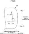
- FIG. 1 is a schematic plan view illustrating a front portion of a vehicle 100 on which an engine 1, to which a cover member mounting structure according to the present embodiment is applied, is mounted.
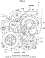
- FIG. 2 illustrates the engine 1 as seen from the front.
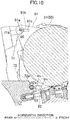
- FIG. 3 is a cross-sectional view taken along line III-III in FIG. 2 , illustrating the section of the engine 1 as viewed from the right.
- the vehicle 100 is configured as a front-engine, front-wheel-drive vehicle (FF vehicle).
- FF vehicle front-wheel-drive vehicle
- the cover member mounting structure of the present embodiment is not limited to the FF vehicle, and may be applied to an engine mounted on an FR vehicle, an MR vehicle, or an RR vehicle.
- a "front-rear direction” is the same as a longitudinal direction of the vehicle 100 as shown in FIG. 1 , and in this direction, the side toward an engine body 10 is defined as the rear side, and the side opposite to the engine body 10 is defined as the front side, as shown in FIG. 3 .
- a "left-right direction” is the same as a vehicle width direction of the vehicle 100 as shown in FIG. 3 , and in this direction, the driving side of the engine 1 is defined as the right side, and the side opposite to the driving side is defined as the left side, as shown in FIG. 2 .
- a “vertical direction” is the same as a direction perpendicular to the "front-rear direction” and the "left-right direction,” i.e., a direction perpendicular to the road surface, and in this direction, the side toward a cylinder head 12 is defined as the upper side, and the side toward a cylinder block 11 is defined as the lower side, as shown in FIG. 3 .
- the engine body 10 is formed so that an axial direction of cylinder bores 11a is slightly inclined with respect to the "vertical direction” as shown in FIG. 3 .
- the engine 1 mounted on the vehicle 100 is a multi-cylinder internal combustion engine. Specifically, the engine 1 disclosed herein is an inline-four gasoline engine. The engine 1 is "transversely" mounted such that the direction in which the cylinders are arranged substantially coincide with the vehicle width direction, and is configured as a so-called front intake and rear exhaust engine.
- the engine 1 includes an engine body 10 having a cylinder block 11 and a cylinder head 12.
- Various members including a plurality of accessories 50 are attached to an outer wall of the engine body 10.
- Cylinder bores 11a are formed in the cylinder block 11, and pistons (not shown) move up and down in the cylinder bores 11a.
- a combustion chamber is formed by a surface of each piston, a wall surface of each cylinder bore 11a, and a wall surface of the cylinder head 12.
- the pistons are connected to a crankshaft 15 provided below the cylinder block 11 via a connecting rod (not shown), and power obtained by combustion of an air-fuel mixture in the combustion chambers is delivered to the outside through the crankshaft 15.
- the accessories 50 are peripheral devices provided for assisting an engine operation of the engine body 10. Examples thereof include a supercharger 53, an alternator 51 (peripheral member), and an air compressor 52 used for the air-conditioning purpose which are sequentially arranged from the top along a front outer wall 10b of the engine body 10, a water pump (not shown) for cooling an engine coolant arranged along a rear outer wall of the engine body 10, an intake device, an exhaust device, and a fuel injector which are not shown and provided for the cylinder head 12, and a starting device provided around the engine body 10.
- the supercharger 53 compresses intake air to increase a substantial amount of exhaust gas from the engine 1.
- the air compressor 52 is used for conditioning the air in the vehicle 100.
- the water pump functions as a pump, and constitutes a cooling system for the engine 1.
- an accessory drive system 60 configured to drive and couple the engine body 10 and the accessories 50 is arranged on the right end side of the crankshaft 15 in a long axis direction thereof.
- the accessory drive system 60 includes a crankshaft pulley 65, an alternator drive pulley 61, an air compressor drive pulley 62, a water pump drive pulley (not shown), a plurality of driven pulleys (details are omitted), an automatic tensioner (e.g., a double arm tensioner 66), an inner belt 69a, and an outer belt 69b.
- a crankshaft pulley 65 an alternator drive pulley 61, an air compressor drive pulley 62, a water pump drive pulley (not shown), a plurality of driven pulleys (details are omitted), an automatic tensioner (e.g., a double arm tensioner 66), an inner belt 69a, and an outer belt 69b.
- crankshaft pulley 65, the alternator drive pulley 61, the air compressor drive pulley 62, the double arm tensioner 66, and the inner belt 69a form a first drive system 60a
- the crankshaft pulley 65, the water pump drive pulley, the driven pulleys, and the outer belt 69b form a second drive system 60b independent of the first drive system 60a.
- the first and second drive systems 60a and 60b have similar driving modes. Thus, how the accessories 50 are driven will be described taking the first drive system 60a as an example, and the description of the second driving system 60b will not be repeated.
- operation of the engine body 10 allows the crankshaft pulley 65 to be rotationally driven via the crankshaft 15. Rotation of the crankshaft pulley 65 allows its power to be transmitted through the inner belt 69a to the alternator drive pulley 61 and the air compressor drive pulley 62. Power transmitted to each of the pulleys is used to drive an associated one of the accessories. In other words, the alternator drive pulley 61 rotates under the transmitted power, and actuates the alternator 51.
- the air compressor drive pulley 62 actuates the air compressor 52. Provision of the double arm tensioner 66 allows tension T of the inner belt 69a to be kept substantially constant. In this manner, the accessories 50 are driven by the power outputted from the crankshaft 15.
- the alternator 51 will be described in detail below.
- the alternator 51 is arranged near the right end of the outer wall 10b of the engine body 10 to generate an alternating current for use in an electrical system.
- the alternator 51 is attached to the outer wall 10b of the engine body 10 via a support. That is, the support includes an engine body support 70 provided separately from or integrally with the outer wall 10b of the engine body 10, an accessory support 80 provided separately from or integrally with the alternator 51, and bolts 90 for connecting the engine body support 70 and the accessory support 80.
- the engine body support 70 includes an upper engine body support 71 and a lower engine body support 72.
- the accessory support 80 includes an upper accessory support 81 and a lower accessory support 82.
- the upper engine body support 71 is connected to the upper accessory support 81 by the bolt 90
- the lower engine body support 72 is connected to the lower accessory support 82 by the bolt 90.
- the upper and lower accessory supports 81 and 82 that constitute the accessory support 80 are both provided to protrude from a rear portion of the alternator 51 toward the engine body 10 in a substantially flange shape.
- the upper accessory support 81 has an upper accessory shaft hole 81a through which the bolt 90 is inserted along the left-right direction.
- This upper accessory shaft hole 81a has a circular cross section, and has a slightly larger diameter than the bolt 90.
- the bolt 90 inserted through the upper accessory shaft hole 81a moves integrally with the alternator 51.
- the lower accessory support 82 also has a lower accessory shaft hole 82a configured similarly to the upper accessory shaft hole 81a.
- the engine body support 70 is provided with a guide mechanism that allows the alternator 51 to move toward the engine body 10 when a load is inputted to the alternator 51 in the direction toward the engine body 10, that is, in the direction from the front side to the rear side of the alternator 51.
- a groove extending in the front-rear direction is cut as the guide mechanism in the upper engine body support 71.
- the groove is formed by an upper shaft hole 71a, an upper intermediate portion 71b, and an upper elongated hole 71c.
- the lower engine body support 72 is also provided with a groove that serves as the guide mechanism and is formed by a lower shaft hole 72a, a lower intermediate portion 72b, and a lower elongated hole 72c.
- the upper and lower shaft holes 71a and 72a may be referred to as a "shaft hole 71a, 72a”
- the upper and lower intermediate portions 71b and 72b may be referred to as an “intermediate portion 71b, 72b”
- the upper and lower elongated holes 71c and 72c may be referred to as an "elongated hole 71c, 72c.”
- the shaft hole 71a, 72a is provided to receive the bolt 90 inserted therein, and has a circular cross section and a slightly larger diameter than the bolt 90.
- the intermediate portion 71b, 72b is provided adjacent to the side of the shaft hole 71a, 72a toward the engine body 10, and is formed as a groove having a vertical height smaller than the vertical diameter of the shaft hole 71a, 72a. Further, the intermediate portion 71b, 72b is configured to have a vertical height slightly smaller than the diameter of the shaft portion of the bolt 90.
- the support supports and regulates the alternator 51 not to move in the front-rear direction, i.e., not to move toward nor away from the engine body 10.
- the elongated hole 71c, 72c is provided adjacent to the side of the intermediate portion 71b, 72b toward the engine body 10 to extend in the front-rear direction, and has a vertical height substantially equal to or greater than the vertical diameter of the shaft hole 71a, 72a. For example, when a load equal to or greater than a predetermined value is inputted from the front to the vehicle 100 upon head-on collision, the bolt 90 passes through the intermediate portion 71b, 72b and slides inside the elongated hole 71c, 72c.
- the alternator 51 is guided by the intermediate portion 71b, 72b and the elongated hole 71c, 72c to be able to move toward the engine body 10 by the length in the front-rear direction of the intermediate portion 71b, 72b and the elongated hole 71c, 72c.
- the alternator 51 is maintained at a normal position during the normal operation, and is moved toward the engine body 10 when a load equal to or greater than a predetermined value is inputted to the engine 1 from the front.
- the load can be efficiently absorbed, and serious damage to the engine body 10 can be reduced.
- the intermediate portion 71b, 72b and the elongated hole 71c, 72c respectively have appropriate lengths in the front-rear direction so that the alternator 51 does not make contact with the engine body 10 when the alternator 51 moves.
- a cover member 41 is arranged between the outer wall 10b and the alternator 51.
- a harness 42 to be connected to various sensors is routed between the outer wall 10b and the cover member 41.
- the harness 42 is held on the side of the cover member 41 facing the outer wall 10b, i.e., on the surface of the cover member 41 facing the engine body 10. The configuration will be described in detail below.
- the cover member 41 is arranged in front of the cylinder block 11, and functions as a thermal insulator, a protector, and a sound insulator for the engine body 10.
- the cover member 41 can be made of any material as long as it can function as the thermal insulator, the protector, and the sound insulator for the engine body 10. Specific examples of such a material include a resin such as a urethane resin.
- the cover member 41 may be arranged on a portion of the outer wall 10b of the engine body 10, or almost entirely on the outer wall 10b including the position to which the harness 42 is routed.
- the cover member 41 can be formed by injection molding, extrusion molding, vacuum molding, or foam molding.
- a harness groove 41a (groove) is formed in a portion of the cover member 41 facing the outer wall 10b, i.e., in the surface facing the engine body 10.
- the harness 42 is held with a harness body 42a thereof, which will be described later, received in the harness groove 41a.
- the harness groove 41a has a vertical height, i.e., a groove width, which is substantially equal to the diameter of the harness body 42a.
- the harness groove 41a can securely fix and hold the harness body 42a that is pushed into it.
- the harness body 42a which is merely pushed into the harness groove 41a, allows the harness 42 to be easily taken out for replacement.
- the harness body 42a received in the harness groove 41a, can block the harness 42 from displacement during the assembly of the harness 42, the cover member 41, and the alternator 51 to the engine body 10, or when the vehicle 100 vibrates.
- the depth of the harness groove 41a is not particularly limited as long as it can hold the harness 42. However, to securely hold the harness 42 and to protect the harness 42 from damage due to contact with the outer wall 10b of the engine body 10, the depth is desirably greater than the diameter of the harness 42. Specifically, the depth of the harness groove 41a is desirably set such that the harness body 42a makes no contact with the surface of the outer wall 10b, i.e., is preferably held at a predetermined distance from the outer wall 10b, for example, when the harness 42 is received in the harness groove 41a to be assembled to the outer wall 10b of the engine body 10 as shown in FIG. 5 .
- a portion of the harness body 42a in contact with the cover member 41 is entirely received in the harness groove 41a.
- the harness groove 41a may be formed to receive only a portion of the harness body 42a, but in a preferred embodiment, the harness groove 41a is configured to receive the entire portion of the harness body 42a making contact with the cover member 41 from the viewpoint of protecting the harness 42.
- the cover member 41 may have another groove on the side thereof toward the engine body 10 in addition to the harness groove 41a. This can keep the cover member 41 flexible, and facilitates the assembly to the engine body 10.
- FIG. 6 is a view illustrating the cover member 41 as viewed from behind, that is, from the engine body 10 side.
- the harness 42 includes the harness body 42a, and a connector portion 42b which is formed on at least one end of the harness body 42a for connection to a different member such as various sensors or any other components.
- the harness groove 41a of the cover member 41 receives the harness body 42a, and the connector portion 42b is positioned outside the cover member 41.
- the connector portion 42b is provided on each of the upper and lower ends of the cover member 41. The position and number of the connector portions 42b can be appropriately set according to the configuration of the engine 1.
- FIG. 7 is a front view of the engine 1 from which some of the members are removed.
- FIG. 8 is a view illustrating a state in which the alternator 51 shown in FIG. 7 is removed.
- the harness body 42a of the harness 42 covered with the cover member 41 includes a first harness body 42a1 and a second harness body 42a2.
- the first harness body 42a1 is located between the alternator 51 and the engine body 10
- the second harness body 42a2 is not located between the alternator 51 and the engine body 10.
- the first harness body 42a1 and the cover member 41 covering the first harness body 42al are present.
- the alternator 51 can move toward the engine body 10. That is, the alternator 51 is pressed against the cover member 41.
- the first harness body 42al is inserted into the harness groove 41a and covered with the cover member 41, so that the first harness body 42a1 can be protected from damage even when the alternator 51 moves back toward the engine body 10.
- the first harness body 42a1 inserted into and protected by the harness groove 41a can ensure sufficient space for the rearward movement of the alternator 51 in case of collision, so that the alternator 51 can effectively absorb the load.
- the harness 42 is protected from electromagnetic noise (made less susceptible to noise) of the alternator 51 by the cover member 41. This can increase the degree of flexibility in the routing of the harness 42.
- the harness 42 on the surface of the cover member 41 can reduce the increase in thickness of the cover member 41 as compared to the case in which the harness is embedded in the cover member 41.
- the outer wall 10b and the alternator 51 are brought close to each other. This can achieve appropriate layout of the alternator 51.
- the portion where the alternator 51 is not arranged, i.e., the portion where the second harness body 42a2 is routed, can contribute to the downsizing of the engine 1.
- the connector portion 42b projects outward of the cover member 41 with respect to the harness body 42a of the harness 42 covered with the cover member 41. This can ensure ease of removal of members, such as sensors including an oil level sensor, to which the harness 42 is connected.
- a method for mounting the cover member mounting structure according to the present embodiment will be described below. Specifically, as indicated by an arrow S1 in FIG. 7 , the harness 42 is inserted into the harness groove 41a of the cover member 41. Next, as indicated by an arrow S2, the cover member 41 in which the harness 42 is inserted is attached to the outer wall 10b of the engine body 10. Then, as indicated by an arrow S3, the alternator 51 is attached to the front side of the cover member 41.
- the harness groove 41a of the cover member 41 positions the harness 42. This can facilitate the attachment of the harness 42 and the assembly of the peripheral members such as the alternator 51 to the engine body 10 as compared to a conventional method in which the harness 42 is directly fixed to the outer wall of the engine body 10, and then the peripheral members are assembled.
- the harness groove 41a may be provided in the portion of the cover member 41 facing the alternator 51, i.e., the surface facing the accessory 50, to receive the harness 42 in the harness groove 41a.
- the harness 42 is received in the harness groove 41a of the cover member 41, but how the harness 42 is held on the surface of the cover member 41 is not limited to the configuration of the embodiments described above.
- the harness 42 may be fixed to the surface of the cover member 41 facing the engine body 10 or the alternator 51 with a jig. Note that the configuration of the first embodiment is desirable from the viewpoint of protecting the harness 42.
- the intermediate portion 71b, 72b is formed into a groove shape having a smaller vertical height than the shaft hole 71a, 72a.
- any configuration may be employed as long as the intermediate portion 71b, 72b permits the bolt 90 to move toward the elongated hole 71c, 72c, for example, when a load equal to or greater than a predetermined value is inputted to the alternator 51 in the direction toward the engine body 10.
- the intermediate portion may be formed as a fragile portion in the shape of a narrow bar that breaks to allow the bolt 90 to move when a load is inputted.
- a groove formed by the shaft hole 71a, 72a, the intermediate portion 71b, 72b, and the elongated hole 71c, 72c is cut in the engine body support 70 as a guide mechanism.
- the groove is not limited to this configuration, and any configuration may be employed as long as the alternator 51 moves toward the engine body 10 to absorb a load which is greater than the predetermined value and inputted to the alternator 51 in the direction toward the engine body 10, so that the engine body 10 can be protected from damage.
- a groove serving as a guide mechanism may be cut in the accessory support 80. That is, in the configuration shown in FIG. 10 , the engine body support 70 is provided with the shaft hole 71a, 72a only, and has no intermediate portion 71b, 72b and elongated hole 71c, 72c.
- the upper accessory support 81 as the accessory support 80 is provided with a groove formed by the upper accessory shaft hole 81a, an upper accessory intermediate portion 81b extending forward of the upper accessory shaft hole 81a, and an upper accessory elongated hole 81c extending forward of the upper accessory intermediate portion 81b.
- the lower accessory support 82 is also provided with a groove formed by the lower accessory shaft hole 82a, a lower accessory intermediate portion 82b, and a lower accessory elongated hole 82c, as a guide mechanism.
- the engine which is transversely arranged in the above, may be longitudinally arranged.
- the present invention is not limited to the in-line four-cylinder engine, and may be applied to single cylinder engines, and multi-cylinder engines such as other in-line engines, V engines, and horizontally opposed engines.
- the invention is not limited to the gasoline engine, and may be applied to a diesel engine.
- the accessory 50 in particular, the alternator 51, is attached as the peripheral member.
- the peripheral member is not limited thereto, and may be other accessories 50 described in the first embodiment, or components arranged around the engine body 10.
- the alternator 51 is configured to move toward the engine body 10 when a load equal to or greater than a predetermined value is inputted in the direction toward the engine body 10. However, the alternator 51 does not have to move. If the accessories 50 other than the alternator 51 or other components are arranged as the peripheral members, they may be configured to move just like the alternator 51, or not to move, when the load is inputted.
Landscapes
- Engineering & Computer Science (AREA)
- Mechanical Engineering (AREA)
- General Engineering & Computer Science (AREA)
- Chemical & Material Sciences (AREA)
- Combustion & Propulsion (AREA)
- Physics & Mathematics (AREA)
- Acoustics & Sound (AREA)
- Cylinder Crankcases Of Internal Combustion Engines (AREA)
- General Details Of Gearings (AREA)
- Motor Or Generator Frames (AREA)
Abstract
Description
- The present disclosure relates to an engine cover member mounting structure.
- For the purpose of thermal and sound insulation of an engine, a cover member can be provided on an outer wall of a cylinder block.
- A harness for an oil level sensor or any other components is arranged around the cylinder block, and thus, the position of the harness needs to be considered if the cover member is attached.
- For example,
Patent Document 1 discloses a structure in which a harness is embedded in a sound insulator attached to an outer surface of a transmission. - Patent Document 1: Japanese Unexamined Patent Publication No.
2014-163408 - However, if the harness is embedded in the cover member with reference to the technology described in
Patent Document 1, repair and replacement of the harness cannot be performed easily. In addition, peripheral members, e.g., an intake system, and accessories such as an alternator and a compressor for an air conditioner, are arranged on an outer wall of an engine body. Embedding the harness in the cover member makes the cover member thick, and makes the peripheral members separated from the engine body. This is inconvenient from the viewpoint of layout. - Therefore, it is an object of the present disclosure to provide an engine cover member mounting structure capable of properly routing a harness, facilitating repair and replacement of the harness, and downsizing an engine through appropriate layout of the engine and peripheral members.
- In order to solve the above problem, in the present disclosure, a harness is held on a surface of a cover member.
- Specifically, an engine cover member mounting structure disclosed herein includes: an engine body; a peripheral member arranged on an outer wall of the engine body; a cover member arranged between the outer wall and the peripheral member; and a harness routed between the outer wall and the peripheral member, and the harness is held on a surface of the cover member.
- With this configuration, when the peripheral member is arranged on the outer wall of the engine, the harness is held on the surface of the cover member arranged between the outer wall of the engine and the peripheral member, so that the harness is routed between the outer wall of the engine and the peripheral member. Thus, the harness can be repaired and replaced more easily than the harness embedded in the cover member. This can reduce the increase in thickness of the cover member, and can reduce the distance between the engine body and the peripheral member, thereby achieving appropriate layout of the peripheral member.
- In a preferred embodiment, the harness is held on a surface of the cover member facing the outer wall.
- With this configuration, the harness is held on the surface of the cover member facing the outer wall of the engine. This can effectively protect the harness from damage during the assembly, repair, or replacement of the peripheral member.
- Moreover, an engine cover member mounting structure disclosed herein includes: an engine body; a peripheral member arranged on an outer wall of the engine body; a cover member arranged between the outer wall and the peripheral member; and a harness routed between the outer wall and the cover member, and the harness is held on a surface of the cover member facing the outer wall.
- With this configuration, the harness is held on the surface of the cover member facing the engine body so that the harness is routed between the outer wall of the engine and the cover member. This can reduce the increase in thickness of the cover member, and can contribute to the downsizing of the engine, compared to the case in which the harness is embedded in the cover member.
- In a preferred embodiment, a groove is formed in the surface of the cover member facing the outer wall, and the groove receives the harness.
- With this configuration, the harness is received and held in the groove formed in the surface of the cover member facing the engine body. This can hold the harness easily and block the harness from displacement without need of any additional member for holding the harness, and can facilitate the replacement of the harness.
- In a preferred embodiment, the peripheral member is attached to the outer wall of the engine body via a support, and the support is provided with a guide mechanism that allows the peripheral member to move toward the engine body when a load is inputted to the peripheral member in a direction toward the engine body.
- The support of the peripheral member is provided with the guide mechanism that allows the peripheral member to move toward the engine body. Thus, when a load acts on the peripheral member in a direction toward the engine body, i.e., in a direction from the side opposite to the engine body toward the engine body, upon collision of the vehicle, for example, the peripheral member can move to absorb the load, thereby protecting the engine body from serious damage. In the engine including such a guide mechanism, the harness of this configuration is received in the groove formed in the cover member. This can protect the harness when the peripheral member moves, and can ensure sufficient space for the movement of the peripheral member toward the engine body. Thus, the peripheral member can effectively absorb the load inputted.
- In a preferred embodiment, the peripheral member is an accessory, in particular, an alternator.
- With this configuration, the cover member can reduce the influence of, for example, electromagnetic noise of the alternator on the harness. This can increase the degree of flexibility in the routing of the harness.
- In a preferred embodiment, a connector portion is formed on at least one end of the harness for connection to a different member, and the connector portion is positioned outside the cover member.
- This configuration can ensure ease of removal of members, such as an oil level sensor, to which the harness is connected.
- Further, an engine cover member mounting structure disclosed herein includes: an engine body; an accessory arranged on an outer wall of the engine body facing forward in a longitudinal direction of a vehicle; a cover member arranged between the outer wall and the accessory; and a harness routed between the outer wall and the accessory. The accessory is attached to the outer wall of the engine body via a support. The support is provided with a guide mechanism that allows the accessory to move rearward when a load toward a rear side in the longitudinal direction of the vehicle is inputted to the accessory. The harness is held in a groove formed to be recessed in a thickness direction of the cover member in a surface of the cover member facing the outer wall. A connector portion is formed on at least one end of the harness for connection to a different member, and the connector portion is positioned outside the cover member and the accessory when viewed from the front of the vehicle.
- As can be seen in the foregoing, with this configuration, when the peripheral member is arranged on the outer wall of the engine, the harness is held on the surface of the cover member arranged between the outer wall of the engine and the peripheral member, so that the harness is routed between the outer wall of the engine and the peripheral member. Thus, the harness can be repaired and replaced more easily than the harness embedded in the cover member. This can reduce the increase in thickness of the cover member, and can reduce the distance between the engine body and the peripheral member, thereby achieving appropriate layout of the peripheral member.
-
- [
FIG. 1] FIG. 1 is a schematic plan view illustrating a vehicle on which an engine having a cover member mounting structure according to an embodiment is mounted. - [
FIG. 2] FIG. 2 is a front view illustrating the engine as viewed from the front. - [
FIG. 3] FIG. 3 is a cross-sectional view taken along line III-III inFIG. 2 . - [
FIG. 4] FIG. 4 is a right side view illustrating an accessory drive system of the engine shown inFIG. 2 . - [
FIG. 5] FIG. 5 is an enlarged view illustrating a portion near an alternator shown inFIG. 3 . - [
FIG. 6] FIG. 6 is a view as seen from a cylinder block side, illustrating a cover member to which a harness is attached. - [
FIG. 7] FIG. 7 is a view illustrating a state where some of the members shown inFIG. 2 are removed. - [
FIG. 8] FIG. 8 is a view illustrating a state where the alternator shown inFIG. 6 is removed. - [
FIG. 9] FIG. 9 is a view illustrating how the cover member is attached in a cover member mounting structure according to the present embodiment. - [
FIG. 10] FIG. 10 is a view illustrating a configuration of a support of an alternator according to a fifth embodiment. - Embodiments of the present disclosure will be described in detail with reference to the drawings. The following embodiments are merely exemplary ones in nature, and are not intended to limit the scope, applications, or use of the disclosure.
-
FIG. 1 is a schematic plan view illustrating a front portion of avehicle 100 on which anengine 1, to which a cover member mounting structure according to the present embodiment is applied, is mounted.FIG. 2 illustrates theengine 1 as seen from the front.FIG. 3 is a cross-sectional view taken along line III-III inFIG. 2 , illustrating the section of theengine 1 as viewed from the right. - The
vehicle 100 is configured as a front-engine, front-wheel-drive vehicle (FF vehicle). The cover member mounting structure of the present embodiment is not limited to the FF vehicle, and may be applied to an engine mounted on an FR vehicle, an MR vehicle, or an RR vehicle. - In this specification, the directions are defined relative to the
vehicle 100 placed on a road surface. That is, a "front-rear direction" is the same as a longitudinal direction of thevehicle 100 as shown inFIG. 1 , and in this direction, the side toward anengine body 10 is defined as the rear side, and the side opposite to theengine body 10 is defined as the front side, as shown inFIG. 3 . A "left-right direction" is the same as a vehicle width direction of thevehicle 100 as shown inFIG. 3 , and in this direction, the driving side of theengine 1 is defined as the right side, and the side opposite to the driving side is defined as the left side, as shown inFIG. 2 . A "vertical direction" is the same as a direction perpendicular to the "front-rear direction" and the "left-right direction," i.e., a direction perpendicular to the road surface, and in this direction, the side toward acylinder head 12 is defined as the upper side, and the side toward acylinder block 11 is defined as the lower side, as shown inFIG. 3 . Note that theengine body 10 is formed so that an axial direction ofcylinder bores 11a is slightly inclined with respect to the "vertical direction" as shown inFIG. 3 . - The
engine 1 mounted on thevehicle 100 is a multi-cylinder internal combustion engine. Specifically, theengine 1 disclosed herein is an inline-four gasoline engine. Theengine 1 is "transversely" mounted such that the direction in which the cylinders are arranged substantially coincide with the vehicle width direction, and is configured as a so-called front intake and rear exhaust engine. - As shown in
FIG. 3 , theengine 1 includes anengine body 10 having acylinder block 11 and acylinder head 12. Various members including a plurality of accessories 50 (peripheral members) are attached to an outer wall of theengine body 10. - Cylinder bores 11a are formed in the
cylinder block 11, and pistons (not shown) move up and down in the cylinder bores 11a. A combustion chamber is formed by a surface of each piston, a wall surface of eachcylinder bore 11a, and a wall surface of thecylinder head 12. The pistons are connected to acrankshaft 15 provided below thecylinder block 11 via a connecting rod (not shown), and power obtained by combustion of an air-fuel mixture in the combustion chambers is delivered to the outside through thecrankshaft 15. - The
accessories 50 are peripheral devices provided for assisting an engine operation of theengine body 10. Examples thereof include asupercharger 53, an alternator 51 (peripheral member), and anair compressor 52 used for the air-conditioning purpose which are sequentially arranged from the top along a frontouter wall 10b of theengine body 10, a water pump (not shown) for cooling an engine coolant arranged along a rear outer wall of theengine body 10, an intake device, an exhaust device, and a fuel injector which are not shown and provided for thecylinder head 12, and a starting device provided around theengine body 10. For example, thesupercharger 53 compresses intake air to increase a substantial amount of exhaust gas from theengine 1. Theair compressor 52 is used for conditioning the air in thevehicle 100. The water pump functions as a pump, and constitutes a cooling system for theengine 1. - As shown in
FIGS. 2 and4 , anaccessory drive system 60 configured to drive and couple theengine body 10 and theaccessories 50 is arranged on the right end side of thecrankshaft 15 in a long axis direction thereof. - The
accessory drive system 60 includes acrankshaft pulley 65, analternator drive pulley 61, an air compressor drivepulley 62, a water pump drive pulley (not shown), a plurality of driven pulleys (details are omitted), an automatic tensioner (e.g., a double arm tensioner 66), aninner belt 69a, and anouter belt 69b. Thecrankshaft pulley 65, the alternator drivepulley 61, the air compressor drivepulley 62, thedouble arm tensioner 66, and theinner belt 69a form afirst drive system 60a, and thecrankshaft pulley 65, the water pump drive pulley, the driven pulleys, and theouter belt 69b form asecond drive system 60b independent of thefirst drive system 60a. - The first and
second drive systems accessories 50 are driven will be described taking thefirst drive system 60a as an example, and the description of thesecond driving system 60b will not be repeated. In thefirst drive system 60a, as shown inFIG. 4 , operation of theengine body 10 allows thecrankshaft pulley 65 to be rotationally driven via thecrankshaft 15. Rotation of thecrankshaft pulley 65 allows its power to be transmitted through theinner belt 69a to the alternator drivepulley 61 and the air compressor drivepulley 62. Power transmitted to each of the pulleys is used to drive an associated one of the accessories. In other words, the alternator drivepulley 61 rotates under the transmitted power, and actuates thealternator 51. Likewise, the air compressor drivepulley 62 actuates theair compressor 52. Provision of thedouble arm tensioner 66 allows tension T of theinner belt 69a to be kept substantially constant. In this manner, theaccessories 50 are driven by the power outputted from thecrankshaft 15. - The
alternator 51 will be described in detail below. - As shown in
FIGS. 2 and3 , thealternator 51 is arranged near the right end of theouter wall 10b of theengine body 10 to generate an alternating current for use in an electrical system. - As shown in
FIG. 5 , thealternator 51 is attached to theouter wall 10b of theengine body 10 via a support. That is, the support includes anengine body support 70 provided separately from or integrally with theouter wall 10b of theengine body 10, anaccessory support 80 provided separately from or integrally with thealternator 51, andbolts 90 for connecting theengine body support 70 and theaccessory support 80. - The
engine body support 70 includes an upperengine body support 71 and a lowerengine body support 72. Theaccessory support 80 includes anupper accessory support 81 and alower accessory support 82. The upperengine body support 71 is connected to theupper accessory support 81 by thebolt 90, and the lowerengine body support 72 is connected to thelower accessory support 82 by thebolt 90. - As shown in
FIG. 5 , the upper and lower accessory supports 81 and 82 that constitute theaccessory support 80 are both provided to protrude from a rear portion of thealternator 51 toward theengine body 10 in a substantially flange shape. Theupper accessory support 81 has an upperaccessory shaft hole 81a through which thebolt 90 is inserted along the left-right direction. This upperaccessory shaft hole 81a has a circular cross section, and has a slightly larger diameter than thebolt 90. Thebolt 90 inserted through the upperaccessory shaft hole 81a moves integrally with thealternator 51. Thelower accessory support 82 also has a loweraccessory shaft hole 82a configured similarly to the upperaccessory shaft hole 81a. - Here, the
engine body support 70 is provided with a guide mechanism that allows thealternator 51 to move toward theengine body 10 when a load is inputted to thealternator 51 in the direction toward theengine body 10, that is, in the direction from the front side to the rear side of thealternator 51. Specifically, as shown inFIG. 5 , a groove extending in the front-rear direction is cut as the guide mechanism in the upperengine body support 71. The groove is formed by anupper shaft hole 71a, an upperintermediate portion 71b, and an upperelongated hole 71c. Almost similarly to the upperengine body support 71, the lowerengine body support 72 is also provided with a groove that serves as the guide mechanism and is formed by alower shaft hole 72a, a lower intermediate portion 72b, and a lowerelongated hole 72c. Hereinafter, the upper andlower shaft holes shaft hole intermediate portions 71b and 72b may be referred to as an "intermediate portion 71b, 72b," and the upper and lowerelongated holes elongated hole - The
shaft hole bolt 90 inserted therein, and has a circular cross section and a slightly larger diameter than thebolt 90. - The
intermediate portion 71b, 72b is provided adjacent to the side of theshaft hole engine body 10, and is formed as a groove having a vertical height smaller than the vertical diameter of theshaft hole intermediate portion 71b, 72b is configured to have a vertical height slightly smaller than the diameter of the shaft portion of thebolt 90. Thus, when the vibration is generated during the normal operation of thevehicle 100, thebolt 90 stays at the position of theshaft hole engine body 10 due to the presence of theintermediate portion 71b, 72b. During the normal operation, the support supports and regulates thealternator 51 not to move in the front-rear direction, i.e., not to move toward nor away from theengine body 10. - The
elongated hole intermediate portion 71b, 72b toward theengine body 10 to extend in the front-rear direction, and has a vertical height substantially equal to or greater than the vertical diameter of theshaft hole vehicle 100 upon head-on collision, thebolt 90 passes through theintermediate portion 71b, 72b and slides inside theelongated hole alternator 51 is guided by theintermediate portion 71b, 72b and theelongated hole engine body 10 by the length in the front-rear direction of theintermediate portion 71b, 72b and theelongated hole - With the above configuration, the
alternator 51 is maintained at a normal position during the normal operation, and is moved toward theengine body 10 when a load equal to or greater than a predetermined value is inputted to theengine 1 from the front. Thus, the load can be efficiently absorbed, and serious damage to theengine body 10 can be reduced. Theintermediate portion 71b, 72b and theelongated hole alternator 51 does not make contact with theengine body 10 when thealternator 51 moves. - As shown in
FIGS. 1 and5 , acover member 41 is arranged between theouter wall 10b and thealternator 51. Aharness 42 to be connected to various sensors is routed between theouter wall 10b and thecover member 41. - One of the features of the cover member mounting structure according to the present embodiment is that the
harness 42 is held on the side of thecover member 41 facing theouter wall 10b, i.e., on the surface of thecover member 41 facing theengine body 10. The configuration will be described in detail below. - As shown in
FIGS. 1 and2 , thecover member 41 is arranged in front of thecylinder block 11, and functions as a thermal insulator, a protector, and a sound insulator for theengine body 10. Thecover member 41 can be made of any material as long as it can function as the thermal insulator, the protector, and the sound insulator for theengine body 10. Specific examples of such a material include a resin such as a urethane resin. Note that thecover member 41 may be arranged on a portion of theouter wall 10b of theengine body 10, or almost entirely on theouter wall 10b including the position to which theharness 42 is routed. Thecover member 41 can be formed by injection molding, extrusion molding, vacuum molding, or foam molding. - A
harness groove 41a (groove) is formed in a portion of thecover member 41 facing theouter wall 10b, i.e., in the surface facing theengine body 10. Theharness 42 is held with aharness body 42a thereof, which will be described later, received in theharness groove 41a. - As shown in
FIG. 5 , theharness groove 41a has a vertical height, i.e., a groove width, which is substantially equal to the diameter of theharness body 42a. Thus, theharness groove 41a can securely fix and hold theharness body 42a that is pushed into it. Theharness body 42a, which is merely pushed into theharness groove 41a, allows theharness 42 to be easily taken out for replacement. Further, theharness body 42a, received in theharness groove 41a, can block theharness 42 from displacement during the assembly of theharness 42, thecover member 41, and thealternator 51 to theengine body 10, or when thevehicle 100 vibrates. - The depth of the
harness groove 41a is not particularly limited as long as it can hold theharness 42. However, to securely hold theharness 42 and to protect theharness 42 from damage due to contact with theouter wall 10b of theengine body 10, the depth is desirably greater than the diameter of theharness 42. Specifically, the depth of theharness groove 41a is desirably set such that theharness body 42a makes no contact with the surface of theouter wall 10b, i.e., is preferably held at a predetermined distance from theouter wall 10b, for example, when theharness 42 is received in theharness groove 41a to be assembled to theouter wall 10b of theengine body 10 as shown inFIG. 5 . - As shown in
FIG. 6 , in the cover member mounting structure according to the present embodiment, a portion of theharness body 42a in contact with thecover member 41 is entirely received in theharness groove 41a. Theharness groove 41a may be formed to receive only a portion of theharness body 42a, but in a preferred embodiment, theharness groove 41a is configured to receive the entire portion of theharness body 42a making contact with thecover member 41 from the viewpoint of protecting theharness 42. - The
cover member 41 may have another groove on the side thereof toward theengine body 10 in addition to theharness groove 41a. This can keep thecover member 41 flexible, and facilitates the assembly to theengine body 10. -
FIG. 6 is a view illustrating thecover member 41 as viewed from behind, that is, from theengine body 10 side. As shown inFIG. 6 , theharness 42 includes theharness body 42a, and aconnector portion 42b which is formed on at least one end of theharness body 42a for connection to a different member such as various sensors or any other components. - The
harness groove 41a of thecover member 41 receives theharness body 42a, and theconnector portion 42b is positioned outside thecover member 41. In the present embodiment, theconnector portion 42b is provided on each of the upper and lower ends of thecover member 41. The position and number of theconnector portions 42b can be appropriately set according to the configuration of theengine 1. -
FIG. 7 is a front view of theengine 1 from which some of the members are removed.FIG. 8 is a view illustrating a state in which thealternator 51 shown inFIG. 7 is removed. - As shown in
FIGS. 7 and8 , in a state where thecover member 41 receiving theharness 42 and thealternator 51 are assembled to theengine body 10, theharness body 42a of theharness 42 covered with thecover member 41 includes a first harness body 42a1 and a second harness body 42a2. When viewed from the front, the first harness body 42a1 is located between thealternator 51 and theengine body 10, but the second harness body 42a2 is not located between thealternator 51 and theengine body 10. - Specifically, at a position where the
alternator 51 is attached, the first harness body 42a1 and thecover member 41 covering the first harness body 42al are present. As described above, when a load equal to or greater than a predetermined value is inputted to thealternator 51 from the front, thealternator 51 can move toward theengine body 10. That is, thealternator 51 is pressed against thecover member 41. At this time, the first harness body 42al is inserted into theharness groove 41a and covered with thecover member 41, so that the first harness body 42a1 can be protected from damage even when thealternator 51 moves back toward theengine body 10. In other words, the first harness body 42a1 inserted into and protected by theharness groove 41a can ensure sufficient space for the rearward movement of thealternator 51 in case of collision, so that thealternator 51 can effectively absorb the load. - Further, the
harness 42 is protected from electromagnetic noise (made less susceptible to noise) of thealternator 51 by thecover member 41. This can increase the degree of flexibility in the routing of theharness 42. - Moreover, holding the
harness 42 on the surface of thecover member 41 can reduce the increase in thickness of thecover member 41 as compared to the case in which the harness is embedded in thecover member 41. At the portion where thealternator 51 is arranged, i.e., the portion where the first harness body 42a1 is routed, theouter wall 10b and thealternator 51 are brought close to each other. This can achieve appropriate layout of thealternator 51. Also the portion where thealternator 51 is not arranged, i.e., the portion where the second harness body 42a2 is routed, can contribute to the downsizing of theengine 1. - The
connector portion 42b projects outward of thecover member 41 with respect to theharness body 42a of theharness 42 covered with thecover member 41. This can ensure ease of removal of members, such as sensors including an oil level sensor, to which theharness 42 is connected. - A method for mounting the cover member mounting structure according to the present embodiment will be described below. Specifically, as indicated by an arrow S1 in
FIG. 7 , theharness 42 is inserted into theharness groove 41a of thecover member 41. Next, as indicated by an arrow S2, thecover member 41 in which theharness 42 is inserted is attached to theouter wall 10b of theengine body 10. Then, as indicated by an arrow S3, thealternator 51 is attached to the front side of thecover member 41. - As described above, by this mounting method, the
harness groove 41a of thecover member 41 positions theharness 42. This can facilitate the attachment of theharness 42 and the assembly of the peripheral members such as thealternator 51 to theengine body 10 as compared to a conventional method in which theharness 42 is directly fixed to the outer wall of theengine body 10, and then the peripheral members are assembled. - Other embodiments according to the present disclosure will be described in detail below. In the following description, components that have been described in the first embodiment are denoted by the same reference numerals, and are not described in detail.
- In contrast to the first embodiment in which the
harness groove 41a is formed in the portion of thecover member 41 facing theouter wall 10b, i.e., the surface facing theengine body 10, theharness groove 41a may be provided in the portion of thecover member 41 facing thealternator 51, i.e., the surface facing theaccessory 50, to receive theharness 42 in theharness groove 41a. - In the above embodiments, the
harness 42 is received in theharness groove 41a of thecover member 41, but how theharness 42 is held on the surface of thecover member 41 is not limited to the configuration of the embodiments described above. For example, theharness 42 may be fixed to the surface of thecover member 41 facing theengine body 10 or thealternator 51 with a jig. Note that the configuration of the first embodiment is desirable from the viewpoint of protecting theharness 42. - In the above embodiments, the
intermediate portion 71b, 72b is formed into a groove shape having a smaller vertical height than theshaft hole intermediate portion 71b, 72b permits thebolt 90 to move toward theelongated hole alternator 51 in the direction toward theengine body 10. Specifically, for example, the intermediate portion may be formed as a fragile portion in the shape of a narrow bar that breaks to allow thebolt 90 to move when a load is inputted. - In the above embodiments, a groove formed by the
shaft hole intermediate portion 71b, 72b, and theelongated hole engine body support 70 as a guide mechanism. The groove is not limited to this configuration, and any configuration may be employed as long as thealternator 51 moves toward theengine body 10 to absorb a load which is greater than the predetermined value and inputted to thealternator 51 in the direction toward theengine body 10, so that theengine body 10 can be protected from damage. - Specifically, for example, as shown in
FIG. 10 , a groove serving as a guide mechanism may be cut in theaccessory support 80. That is, in the configuration shown inFIG. 10 , theengine body support 70 is provided with theshaft hole intermediate portion 71b, 72b andelongated hole upper accessory support 81 as theaccessory support 80 is provided with a groove formed by the upperaccessory shaft hole 81a, an upper accessoryintermediate portion 81b extending forward of the upperaccessory shaft hole 81a, and an upper accessory elongatedhole 81c extending forward of the upper accessoryintermediate portion 81b. Almost similarly to theupper accessory support 81, thelower accessory support 82 is also provided with a groove formed by the loweraccessory shaft hole 82a, a lower accessoryintermediate portion 82b, and a lower accessory elongatedhole 82c, as a guide mechanism. - With this configuration, when the
alternator 51 receives a load in the direction toward theengine body 10, thebolts 90 respectively pass through the upper and lower accessoryintermediate portions holes alternator 51 is guided to move toward theengine body 10. - The engine, which is transversely arranged in the above, may be longitudinally arranged. Further, the present invention is not limited to the in-line four-cylinder engine, and may be applied to single cylinder engines, and multi-cylinder engines such as other in-line engines, V engines, and horizontally opposed engines. In addition, the invention is not limited to the gasoline engine, and may be applied to a diesel engine.
- In the embodiments described above, the
accessory 50, in particular, thealternator 51, is attached as the peripheral member. However, the peripheral member is not limited thereto, and may beother accessories 50 described in the first embodiment, or components arranged around theengine body 10. - In the embodiments described above, the
alternator 51 is configured to move toward theengine body 10 when a load equal to or greater than a predetermined value is inputted in the direction toward theengine body 10. However, thealternator 51 does not have to move. If theaccessories 50 other than thealternator 51 or other components are arranged as the peripheral members, they may be configured to move just like thealternator 51, or not to move, when the load is inputted. -
- 1
- Engine
- 10
- Engine Body
- 10b
- Outer Wall
- 11
- Cylinder Block
- 11a
- Cylinder Bore
- 12
- Cylinder Head
- 15
- Crankshaft
- 41
- Cover Member
- 41a
- Harness Groove (Groove)
- 42
- Harness
- 42a
- Harness Body
- 42al
- First Harness Body
- 42a2
- Second Harness Body
- 42b
- Connector Portion
- 50
- Accessory
- 51
- Alternator (Accessory)
- 52
- Air Compressor (Accessory)
- 53
- Supercharger (Accessory)
- 70
- Engine Body Support (Support)
- 71
- Upper Engine Body Support (Support)
- 71a
- Upper Shaft Hole (Guide Mechanism)
- 71b
- Upper Intermediate Portion (Guide Mechanism)
- 71c
- Upper Elongated Hole (Guide Mechanism)
- 72
- Lower Engine Body Support (Support)
- 72a
- Lower Shaft Hole (Guide Mechanism)
- 72b
- Lower Intermediate Portion (Guide Mechanism)
- 72c
- Lower Elongated Hole (Guide Mechanism)
- 80
- Accessory Support (Support)
- 81
- Upper Accessory Support (Support)
- 81a
- Upper Accessory Shaft Hole (Guide Mechanism)
- 81b
- Upper Accessory Intermediate Portion (Guide Mechanism)
- 81c
- Upper Accessory Elongated Hole (Guide Mechanism)
- 82
- Lower Accessory Support (Support)
- 82a
- Lower Accessory Shaft Hole (Guide Mechanism)
- 82b
- Lower Accessory Intermediate Portion (Guide Mechanism)
- 82c
- Lower Accessory Elongated Hole (Guide Mechanism)
- 90
- Bolt
- 100
- Vehicle
Claims (9)
- An engine cover member mounting structure, comprising:an engine body;a peripheral member arranged on an outer wall of the engine body;a cover member arranged between the outer wall and the peripheral member; anda harness routed between the outer wall and the peripheral member, whereinthe harness is held on a surface of the cover member.
- The engine cover member mounting structure of claim 1, wherein
the harness is held on a surface of the cover member facing the outer wall. - An engine cover member mounting structure, comprising:an engine body;a peripheral member arranged on an outer wall of the engine body;a cover member arranged between the outer wall and the peripheral member; anda harness routed between the outer wall and the cover member, whereinthe harness is held on a surface of the cover member facing the outer wall.
- The engine cover member mounting structure of any one of claims 1 to 3, wherein
a groove is formed in the surface of the cover member facing the outer wall, and the groove receives the harness. - The engine cover member mounting structure of claim 4, wherein
the peripheral member is attached to the outer wall of the engine body via a support, and
the support is provided with a guide mechanism that allows the peripheral member to move toward the engine body when a load is inputted to the peripheral member in a direction toward the engine body. - The engine cover member mounting structure of any one of claims 1 to 5, wherein
the peripheral member is an accessory. - The engine cover member mounting structure of claim 6, wherein the accessory is an alternator.
- The engine cover member mounting structure of any one of claims 1 to 7, wherein
a connector portion is formed on at least one end of the harness for connection to a different member, and
the connector portion is positioned outside the cover member. - An engine cover member mounting structure, comprising:an engine body;an accessory arranged on an outer wall of the engine body facing forward in a longitudinal direction of a vehicle;a cover member arranged between the outer wall and the accessory; anda harness routed between the outer wall and the accessory, whereinthe accessory is attached to the outer wall of the engine body via a support, andthe support is provided with a guide mechanism that allows the accessory to move rearward when a load toward a rear side in the longitudinal direction of the vehicle is inputted to the accessory,the harness is held in a groove formed to be recessed in a thickness direction of the cover member in a surface of the cover member facing the outer wall,a connector portion is formed on at least one end of the harness for connection to a different member, andthe connector portion is positioned outside the cover member and the accessory when viewed from the front of the vehicle.
Applications Claiming Priority (2)
| Application Number | Priority Date | Filing Date | Title |
|---|---|---|---|
| JP2017161422A JP6521004B2 (en) | 2017-08-24 | 2017-08-24 | Engine cover member mounting structure |
| PCT/JP2018/029125 WO2019039227A1 (en) | 2017-08-24 | 2018-08-02 | Cover member mounting structure for engine |
Publications (2)
| Publication Number | Publication Date |
|---|---|
| EP3663560A1 true EP3663560A1 (en) | 2020-06-10 |
| EP3663560A4 EP3663560A4 (en) | 2020-08-19 |
Family
ID=65439416
Family Applications (1)
| Application Number | Title | Priority Date | Filing Date |
|---|---|---|---|
| EP18849271.4A Withdrawn EP3663560A4 (en) | 2017-08-24 | 2018-08-02 | Cover member mounting structure for engine |
Country Status (5)
| Country | Link |
|---|---|
| US (1) | US11293344B2 (en) |
| EP (1) | EP3663560A4 (en) |
| JP (1) | JP6521004B2 (en) |
| CN (1) | CN111033015B (en) |
| WO (1) | WO2019039227A1 (en) |
Families Citing this family (2)
| Publication number | Priority date | Publication date | Assignee | Title |
|---|---|---|---|---|
| JP6332396B2 (en) * | 2016-10-14 | 2018-05-30 | マツダ株式会社 | Harness mounting structure |
| JP7435316B2 (en) * | 2020-07-01 | 2024-02-21 | マツダ株式会社 | Oil level sensor mounting structure |
Family Cites Families (25)
| Publication number | Priority date | Publication date | Assignee | Title |
|---|---|---|---|---|
| JPH034756Y2 (en) * | 1985-08-27 | 1991-02-07 | ||
| JP2696353B2 (en) | 1988-08-31 | 1998-01-14 | ヤマハ発動機株式会社 | Auxiliary equipment structure of overhead valve type V engine |
| JPH061739U (en) * | 1992-06-11 | 1994-01-14 | マツダ株式会社 | Engine accessory mounting structure |
| US5668351A (en) * | 1996-02-09 | 1997-09-16 | General Motors Corporation | Conduit housing for vehicle engine compartment having a flexible lip that extends into airflow sealing engagement with the radiation |
| JPH09284956A (en) * | 1996-04-12 | 1997-10-31 | Fuji Heavy Ind Ltd | Wire holding structure of universal engine |
| JP2890247B2 (en) * | 1996-04-12 | 1999-05-10 | 本田技研工業株式会社 | Fixing structure of harness holder in engine |
| JP3225866B2 (en) * | 1996-12-18 | 2001-11-05 | トヨタ自動車株式会社 | Wire harness fixing device for internal combustion engine |
| JP3867443B2 (en) * | 1999-05-31 | 2007-01-10 | スズキ株式会社 | Outboard motor cable holding structure |
| JP3709102B2 (en) * | 1999-07-02 | 2005-10-19 | ダイハツ工業株式会社 | Engine accessory mounting structure |
| JP4276336B2 (en) * | 1999-07-08 | 2009-06-10 | ヤマハ発動機株式会社 | Engine wiring harness wiring structure |
| GB0106506D0 (en) * | 2001-03-16 | 2001-05-02 | Perkins Engines Co Ltd | A cylinder block apron |
| JP2004029513A (en) * | 2002-06-27 | 2004-01-29 | Tokai Rubber Ind Ltd | Sound absorbing member and wiring harness wiring structure |
| JP4414875B2 (en) * | 2004-12-22 | 2010-02-10 | 矢崎総業株式会社 | Constant power supply device |
| DE102005030252A1 (en) * | 2005-06-29 | 2007-01-18 | Bayerische Motoren Werke Ag | Multi-cylinder internal combustion engine for vehicles |
| US20090056668A1 (en) * | 2007-09-05 | 2009-03-05 | Gm Global Technology Operations, Inc. | Acoustic Side Cover for an Engine |
| CN201687574U (en) * | 2009-06-12 | 2010-12-29 | 白城市金事达电气有限公司 | Wiring harness guide slot of engine |
| CN201753634U (en) * | 2010-08-17 | 2011-03-02 | 奇瑞汽车股份有限公司 | Wiring harness of engine |
| CN202811073U (en) * | 2012-04-28 | 2013-03-20 | 长城汽车股份有限公司 | Automobile engine noise reduction structure |
| JP2014163408A (en) | 2013-02-21 | 2014-09-08 | Fuji Heavy Ind Ltd | Sound insulation material |
| CN203415916U (en) * | 2013-09-05 | 2014-01-29 | 泰科电子科技(苏州工业园区)有限公司 | Wire harness support, wire harness support apparatus and gearbox with wire harness support apparatus |
| JP6134681B2 (en) * | 2014-03-24 | 2017-05-24 | ヤンマー株式会社 | engine |
| US9551366B2 (en) * | 2014-06-12 | 2017-01-24 | Caterpillar Inc. | Accessory attachment system for machine |
| EP3330514B1 (en) * | 2015-07-31 | 2020-09-09 | Yanmar Co., Ltd. | Tractor |
| JP6309497B2 (en) * | 2015-09-03 | 2018-04-11 | 矢崎総業株式会社 | Electrical junction box and wire harness |
| JP2018071457A (en) * | 2016-10-31 | 2018-05-10 | いすゞ自動車株式会社 | Engine cover |
-
2017
- 2017-08-24 JP JP2017161422A patent/JP6521004B2/en active Active
-
2018
- 2018-08-02 CN CN201880054308.0A patent/CN111033015B/en active Active
- 2018-08-02 WO PCT/JP2018/029125 patent/WO2019039227A1/en not_active Ceased
- 2018-08-02 EP EP18849271.4A patent/EP3663560A4/en not_active Withdrawn
- 2018-08-02 US US16/641,184 patent/US11293344B2/en active Active
Also Published As
| Publication number | Publication date |
|---|---|
| CN111033015B (en) | 2021-11-05 |
| WO2019039227A1 (en) | 2019-02-28 |
| US20210010417A1 (en) | 2021-01-14 |
| EP3663560A4 (en) | 2020-08-19 |
| JP6521004B2 (en) | 2019-05-29 |
| JP2019039343A (en) | 2019-03-14 |
| US11293344B2 (en) | 2022-04-05 |
| CN111033015A (en) | 2020-04-17 |
Similar Documents
| Publication | Publication Date | Title |
|---|---|---|
| US7194994B1 (en) | Bracket assembly for mounting accessories to the front of a small-block Ford motor | |
| US10871135B2 (en) | Internal combustion engine and method for manufacturing internal combustion engine | |
| EP3663560A1 (en) | Cover member mounting structure for engine | |
| EP2261492A1 (en) | Engine body, cooling-water pump arrangement structure of engine and method of forming the same | |
| US7556013B2 (en) | Cover structure for a cooling system component of an internal combustion engine, and engine incorporating same | |
| JP2000038941A (en) | Cylinder fuel injection type engine | |
| US6609491B2 (en) | Multi-cylinder engine and engine auxiliary parts mounting construction | |
| US8820290B2 (en) | Internal combustion engine | |
| JPH11210488A (en) | Fuel pump protection device | |
| CN116438369B (en) | Auxiliary installation structure of internal combustion engine | |
| EP1741920A2 (en) | Attachment structure for engine fuel pump | |
| JP4293399B2 (en) | In-cylinder fuel injection engine | |
| JP2003227346A (en) | Engine accessory mounting structure | |
| US10094512B2 (en) | Accessory support structure for vehicle engine | |
| GB2406882A (en) | Mounting auxiliary parts on i.c. engines | |
| JP7786259B2 (en) | Multi-cylinder engine side structure | |
| JP7786257B2 (en) | Multi-cylinder engine side structure | |
| US20110174566A1 (en) | Internal Combustion Engine and Vehicle Packaging for Same | |
| JP4634341B2 (en) | Engine radiator support structure | |
| EP4433694B1 (en) | Arrangement of auxiliary equipment in the engine bay of a commercial vehicle | |
| US20110114039A1 (en) | Bush and engine that is equipped with the bush | |
| JP4061968B2 (en) | Fuel injection engine and outboard motor | |
| JP6480807B2 (en) | Harness routing structure | |
| JP3503629B2 (en) | Outboard motor auxiliary parts installation structure | |
| JPH11236859A (en) | Engine intake system |
Legal Events
| Date | Code | Title | Description |
|---|---|---|---|
| STAA | Information on the status of an ep patent application or granted ep patent |
Free format text: STATUS: THE INTERNATIONAL PUBLICATION HAS BEEN MADE |
|
| PUAI | Public reference made under article 153(3) epc to a published international application that has entered the european phase |
Free format text: ORIGINAL CODE: 0009012 |
|
| STAA | Information on the status of an ep patent application or granted ep patent |
Free format text: STATUS: REQUEST FOR EXAMINATION WAS MADE |
|
| 17P | Request for examination filed |
Effective date: 20200305 |
|
| AK | Designated contracting states |
Kind code of ref document: A1 Designated state(s): AL AT BE BG CH CY CZ DE DK EE ES FI FR GB GR HR HU IE IS IT LI LT LU LV MC MK MT NL NO PL PT RO RS SE SI SK SM TR |
|
| AX | Request for extension of the european patent |
Extension state: BA ME |
|
| A4 | Supplementary search report drawn up and despatched |
Effective date: 20200721 |
|
| RIC1 | Information provided on ipc code assigned before grant |
Ipc: F02B 77/13 20060101ALI20200715BHEP Ipc: F02B 77/11 20060101ALI20200715BHEP Ipc: F02B 67/00 20060101ALI20200715BHEP Ipc: F02F 7/00 20060101ALI20200715BHEP Ipc: H02G 3/38 20060101ALI20200715BHEP Ipc: H02G 3/04 20060101ALI20200715BHEP Ipc: F02B 77/00 20060101AFI20200715BHEP |
|
| DAV | Request for validation of the european patent (deleted) | ||
| DAX | Request for extension of the european patent (deleted) | ||
| GRAP | Despatch of communication of intention to grant a patent |
Free format text: ORIGINAL CODE: EPIDOSNIGR1 |
|
| STAA | Information on the status of an ep patent application or granted ep patent |
Free format text: STATUS: GRANT OF PATENT IS INTENDED |
|
| INTG | Intention to grant announced |
Effective date: 20210324 |
|
| STAA | Information on the status of an ep patent application or granted ep patent |
Free format text: STATUS: THE APPLICATION IS DEEMED TO BE WITHDRAWN |
|
| 18D | Application deemed to be withdrawn |
Effective date: 20210804 |