EP3663527B1 - Diffusorgehäusewärmeabschirmungen - Google Patents
Diffusorgehäusewärmeabschirmungen Download PDFInfo
- Publication number
- EP3663527B1 EP3663527B1 EP19214262.8A EP19214262A EP3663527B1 EP 3663527 B1 EP3663527 B1 EP 3663527B1 EP 19214262 A EP19214262 A EP 19214262A EP 3663527 B1 EP3663527 B1 EP 3663527B1
- Authority
- EP
- European Patent Office
- Prior art keywords
- platform
- gas turbine
- turbine engine
- recited
- struts
- Prior art date
- Legal status (The legal status is an assumption and is not a legal conclusion. Google has not performed a legal analysis and makes no representation as to the accuracy of the status listed.)
- Active
Links
Images


Classifications
-
- F—MECHANICAL ENGINEERING; LIGHTING; HEATING; WEAPONS; BLASTING
- F01—MACHINES OR ENGINES IN GENERAL; ENGINE PLANTS IN GENERAL; STEAM ENGINES
- F01D—NON-POSITIVE DISPLACEMENT MACHINES OR ENGINES, e.g. STEAM TURBINES
- F01D9/00—Stators
- F01D9/02—Nozzles; Nozzle boxes; Stator blades; Guide conduits, e.g. individual nozzles
- F01D9/04—Nozzles; Nozzle boxes; Stator blades; Guide conduits, e.g. individual nozzles forming ring or sector
- F01D9/041—Nozzles; Nozzle boxes; Stator blades; Guide conduits, e.g. individual nozzles forming ring or sector using blades
-
- F—MECHANICAL ENGINEERING; LIGHTING; HEATING; WEAPONS; BLASTING
- F01—MACHINES OR ENGINES IN GENERAL; ENGINE PLANTS IN GENERAL; STEAM ENGINES
- F01D—NON-POSITIVE DISPLACEMENT MACHINES OR ENGINES, e.g. STEAM TURBINES
- F01D25/00—Component parts, details, or accessories, not provided for in, or of interest apart from, other groups
- F01D25/08—Cooling; Heating; Heat-insulation
- F01D25/14—Casings modified therefor
-
- F—MECHANICAL ENGINEERING; LIGHTING; HEATING; WEAPONS; BLASTING
- F01—MACHINES OR ENGINES IN GENERAL; ENGINE PLANTS IN GENERAL; STEAM ENGINES
- F01D—NON-POSITIVE DISPLACEMENT MACHINES OR ENGINES, e.g. STEAM TURBINES
- F01D25/00—Component parts, details, or accessories, not provided for in, or of interest apart from, other groups
- F01D25/005—Selecting particular materials
-
- F—MECHANICAL ENGINEERING; LIGHTING; HEATING; WEAPONS; BLASTING
- F01—MACHINES OR ENGINES IN GENERAL; ENGINE PLANTS IN GENERAL; STEAM ENGINES
- F01D—NON-POSITIVE DISPLACEMENT MACHINES OR ENGINES, e.g. STEAM TURBINES
- F01D25/00—Component parts, details, or accessories, not provided for in, or of interest apart from, other groups
- F01D25/16—Arrangement of bearings; Supporting or mounting bearings in casings
- F01D25/162—Bearing supports
-
- F—MECHANICAL ENGINEERING; LIGHTING; HEATING; WEAPONS; BLASTING
- F01—MACHINES OR ENGINES IN GENERAL; ENGINE PLANTS IN GENERAL; STEAM ENGINES
- F01D—NON-POSITIVE DISPLACEMENT MACHINES OR ENGINES, e.g. STEAM TURBINES
- F01D5/00—Blades; Blade-carrying members; Heating, heat-insulating, cooling or antivibration means on the blades or the members
- F01D5/12—Blades
- F01D5/28—Selecting particular materials; Particular measures relating thereto; Measures against erosion or corrosion
- F01D5/288—Protective coatings for blades
-
- F—MECHANICAL ENGINEERING; LIGHTING; HEATING; WEAPONS; BLASTING
- F01—MACHINES OR ENGINES IN GENERAL; ENGINE PLANTS IN GENERAL; STEAM ENGINES
- F01D—NON-POSITIVE DISPLACEMENT MACHINES OR ENGINES, e.g. STEAM TURBINES
- F01D5/00—Blades; Blade-carrying members; Heating, heat-insulating, cooling or antivibration means on the blades or the members
- F01D5/12—Blades
- F01D5/14—Form or construction
- F01D5/147—Construction, i.e. structural features, e.g. of weight-saving hollow blades
-
- F—MECHANICAL ENGINEERING; LIGHTING; HEATING; WEAPONS; BLASTING
- F05—INDEXING SCHEMES RELATING TO ENGINES OR PUMPS IN VARIOUS SUBCLASSES OF CLASSES F01-F04
- F05D—INDEXING SCHEME FOR ASPECTS RELATING TO NON-POSITIVE-DISPLACEMENT MACHINES OR ENGINES, GAS-TURBINES OR JET-PROPULSION PLANTS
- F05D2220/00—Application
- F05D2220/30—Application in turbines
- F05D2220/32—Application in turbines in gas turbines
- F05D2220/321—Application in turbines in gas turbines for a special turbine stage
- F05D2220/3216—Application in turbines in gas turbines for a special turbine stage for a special compressor stage
- F05D2220/3219—Application in turbines in gas turbines for a special turbine stage for a special compressor stage for the last stage of a compressor or a high pressure compressor
-
- F—MECHANICAL ENGINEERING; LIGHTING; HEATING; WEAPONS; BLASTING
- F05—INDEXING SCHEMES RELATING TO ENGINES OR PUMPS IN VARIOUS SUBCLASSES OF CLASSES F01-F04
- F05D—INDEXING SCHEME FOR ASPECTS RELATING TO NON-POSITIVE-DISPLACEMENT MACHINES OR ENGINES, GAS-TURBINES OR JET-PROPULSION PLANTS
- F05D2240/00—Components
- F05D2240/10—Stators
- F05D2240/12—Fluid guiding means, e.g. vanes
- F05D2240/121—Fluid guiding means, e.g. vanes related to the leading edge of a stator vane
-
- F—MECHANICAL ENGINEERING; LIGHTING; HEATING; WEAPONS; BLASTING
- F05—INDEXING SCHEMES RELATING TO ENGINES OR PUMPS IN VARIOUS SUBCLASSES OF CLASSES F01-F04
- F05D—INDEXING SCHEME FOR ASPECTS RELATING TO NON-POSITIVE-DISPLACEMENT MACHINES OR ENGINES, GAS-TURBINES OR JET-PROPULSION PLANTS
- F05D2240/00—Components
- F05D2240/10—Stators
- F05D2240/15—Heat shield
-
- F—MECHANICAL ENGINEERING; LIGHTING; HEATING; WEAPONS; BLASTING
- F05—INDEXING SCHEMES RELATING TO ENGINES OR PUMPS IN VARIOUS SUBCLASSES OF CLASSES F01-F04
- F05D—INDEXING SCHEME FOR ASPECTS RELATING TO NON-POSITIVE-DISPLACEMENT MACHINES OR ENGINES, GAS-TURBINES OR JET-PROPULSION PLANTS
- F05D2300/00—Materials; Properties thereof
- F05D2300/10—Metals, alloys or intermetallic compounds
- F05D2300/17—Alloys
- F05D2300/177—Ni - Si alloys
-
- Y—GENERAL TAGGING OF NEW TECHNOLOGICAL DEVELOPMENTS; GENERAL TAGGING OF CROSS-SECTIONAL TECHNOLOGIES SPANNING OVER SEVERAL SECTIONS OF THE IPC; TECHNICAL SUBJECTS COVERED BY FORMER USPC CROSS-REFERENCE ART COLLECTIONS [XRACs] AND DIGESTS
- Y02—TECHNOLOGIES OR APPLICATIONS FOR MITIGATION OR ADAPTATION AGAINST CLIMATE CHANGE
- Y02T—CLIMATE CHANGE MITIGATION TECHNOLOGIES RELATED TO TRANSPORTATION
- Y02T50/00—Aeronautics or air transport
- Y02T50/60—Efficient propulsion technologies, e.g. for aircraft
Definitions
- This application relates to diffuser cases for gas turbine engines, and more particularly to heat shields for diffuser cases.
- a gas turbine engine typically includes a fan section, a compressor section, a combustor section and a turbine section. Air entering the compressor section is compressed and delivered into the combustion section where it is mixed with fuel and ignited to generate a high-speed exhaust gas flow. The high-speed exhaust gas flow expands through the turbine section to drive the compressor and the fan section.
- the compressor section typically includes low and high pressure compressors, and the turbine section includes low and high pressure turbines.
- the compressed air from the compressor section may then pass through a diffuser section.
- the diffuser has an expanding cross sectional area in the direction of the airflow to decrease the velocity and increase the static pressure of the air. This prepares the air for entry into a combustion section at low velocity to permit proper mixing with fuel.
- the diffuser section may be provided by a diffuser case.
- EP 3 431 710 A1 discloses the preamble of claim 1.
- FIG. 1 schematically illustrates a gas turbine engine 20.
- the gas turbine engine 20 is disclosed herein as a two-spool turbofan that generally incorporates a fan section 22, a compressor section 24, a combustor section 26 and a turbine section 28.
- the fan section 22 drives air along a bypass flow path B in a bypass duct defined within a nacelle 15, and also drives air along a core flow path C for compression and communication into the combustor section 26 then expansion through the turbine section 28.
- FIG. 1 schematic
- the exemplary engine 20 generally includes a low speed spool 30 and a high speed spool 32 mounted for rotation about an engine central longitudinal axis A relative to an engine static structure 36 via several bearing systems 38. It should be understood that various bearing systems 38 at various locations may alternatively or additionally be provided, and the location of bearing systems 38 may be varied as appropriate to the application.
- the low speed spool 30 generally includes an inner shaft 40 that interconnects, a first (or low) pressure compressor 44 and a first (or low) pressure turbine 46.
- the inner shaft 40 is connected to the fan 42 through a speed change mechanism, which in exemplary gas turbine engine 20 is illustrated as a geared architecture 48 to drive a fan 42 at a lower speed than the low speed spool 30.
- the high speed spool 32 includes an outer shaft 50 that interconnects a second (or high) pressure compressor 52 and a second (or high) pressure turbine 54.
- a combustor 56 is arranged in exemplary gas turbine 20 between the high pressure compressor 52 and the high pressure turbine 54.
- a mid-turbine frame 57 of the engine static structure 36 may be arranged generally between the high pressure turbine 54 and the low pressure turbine 46.
- the mid-turbine frame 57 further supports bearing systems 38 in the turbine section 28.
- the inner shaft 40 and the outer shaft 50 are concentric and rotate via bearing systems 38 about the engine central longitudinal axis A which is colline
- the core airflow is compressed by the low pressure compressor 44 then the high pressure compressor 52, mixed and burned with fuel in the combustor 56, then expanded over the high pressure turbine 54 and low pressure turbine 46.
- the mid-turbine frame 57 includes airfoils 59 which are in the core airflow path C.
- the turbines 46, 54 rotationally drive the respective low speed spool 30 and high speed spool 32 in response to the expansion.
- gear system 48 may be located aft of the low pressure compressor, or aft of the combustor section 26 or even aft of turbine section 28, and fan 42 may be positioned forward or aft of the location of gear system 48.
- the engine 20 in one example is a high-bypass geared aircraft engine.
- the engine 20 bypass ratio is greater than about six with an example embodiment being greater than about ten
- the geared architecture 48 is an epicyclic gear train, such as a planetary gear system or other gear system, with a gear reduction ratio of greater than about 2.3
- the low pressure turbine 46 has a pressure ratio that is greater than about five.
- the engine 20 bypass ratio is greater than about ten
- the fan diameter is significantly larger than that of the low pressure compressor 44
- the low pressure turbine 46 has a pressure ratio that is greater than about five.
- Low pressure turbine 46 pressure ratio is pressure measured prior to inlet of low pressure turbine 46 as related to the pressure at the outlet of the low pressure turbine 46 prior to an exhaust nozzle.
- the geared architecture 48 may be an epicycle gear train, such as a planetary gear system or other gear system, with a gear reduction ratio of greater than about 2.3:1 and less than about 5:1. It should be understood, however, that the above parameters are only exemplary of one embodiment of a geared architecture engine and that the present invention is applicable to other gas turbine engines including direct drive turbofans.
- the fan section 22 of the engine 20 is designed for a particular flight condition -- typically cruise at about 0.8 Mach and about 35,000 feet (10,668 meters).
- the flight condition of 0.8 Mach and 35,000 ft (10,668 meters), with the engine at its best fuel consumption - also known as "bucket cruise Thrust Specific Fuel Consumption ('TSFC')" - is the industry standard parameter of lbm of fuel being burned divided by lbf of thrust the engine produces at that minimum point.
- "Low fan pressure ratio” is the pressure ratio across the fan blade alone, without a Fan Exit Guide Vane (“FEGV”) system.
- the low fan pressure ratio as disclosed herein according to one non-limiting embodiment is less than about 1.45.
- the "Low corrected fan tip speed” as disclosed herein according to one non-limiting embodiment is less than about 1150 ft / second (350.5 meters/second).
- FIG. 2 schematically illustrates an example diffuser case 62 including an outer diameter (“OD”) ring 64 radially outward of an inner diameter (“ID”) ring 66.
- the OD ring provides a circumferential platform 68
- the ID ring 66 provides a circumferential platform 70.
- the platforms 68, 70 bound an axial portion of the core flow path C and form a diffusing passage 71 therebetween.
- the diffusing passage 71 is located axially between the high pressure compressor 52 and the combustor 56 of the engine 20.
- the diffusing passage 71 has an expanding cross sectional area in the direction of the core flow path C to decrease the velocity and increase the static pressure of the air before reaching the combustor 56.
- One or more circumferentially spaced struts 72 extend from the platform 68 to the platform 70, such that the flow path in the diffusing passage 71 is defined circumferentially between the struts 72.
- one strut 72 is shown in the cross-section of Figure 2 , in some examples, 18-24 equally circumferentially spaced struts 72 are utilized.
- the diffuser case 62, including the OD ring 64, ID ring 66, and struts 72 are formed of a single metal casting. Other materials and arrangements may be utilized.
- the ID ring 66 provides support to the radial load of a rotor support bearing 74 radially inward of the combustor 56.
- the bearing 74 provides a load LA on the diffuser case 62.
- the diffuser case 62 may support additional axial loads, including loads LB and LC from areas of the engine 20 aft (downstream of with respect to the direction of the core flow path C) of the diffuser case 62, in some examples.
- the loads LB and LC are from static components in the high pressure turbine 54 pulling the diffuser case aft.
- the transfer of these loads LA, LB, and LC may affect local stress and resulting component life. Local stress and resulting component life may also be affected by steady state and transient thermal conditions.
- the OD ring 64, ID ring 66, and struts 72 have differing thermal response rates, depending on whether the engine 20 is accelerating or decelerating.
- FIG 3 illustrates an enlarged view (with reference to Figure 2 ) of the diffusing passage 71.
- the strut 72 may be subject to thermal mechanical fatigue, including at the zone 76 near the leading edge 78 of the strut 72.
- Strut 72 responds thermally at a different rate than surrounding structure due to proximity of and exposure to core flow C combined with mass that is low in relation to adjacent outer ring 64 and platform 68 and inner ring 66 and platform 70.
- the strut 72 operates in conditions where it alternately pushes on adjacent rings and platforms, or is be pulled by these components as the engine undergoes acceleration and deceleration impacting overall pressure (compression) ratio and accompanying gas path temperature of flow C.
- zone 76 Combined with externally imparted loads LA and LB, local regions of high internal component loading can be formed at the zone 76 and maybe exacerbated by local changes in diffuser case 62 radial stiffness as load transitions from rings and platforms into relatively thin strut 72.
- the location of zone 76 may also be influenced by the increased stagnation temperature and heat transfer effects of core flow C as it interacts with the leading edge 78 of strut 72.
- the leading edge 78 of the strut 72 is aft of an exit guide vane 80 of the high pressure compressor 52 with respect to the core flow path C, and the platform 68 contacts an outer platform 75A of the exit guide vane 80, and the platform 70 contacts an inner platform 75B of the exit guide vane 80.
- An inner support flange lip 81 extends radially inward from the platform 70.
- One or more flanges 82 may extend axially forward (upstream of with respect to the direction of the core flow path C) from the lip 81.
- the leading edge is axially opposite the trailing edge 60 of the strut.
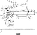
- Figure 4 illustrates a heat shield 84 including a radially outer portion 85 located on the leading edge 78 of the strut 72 and a radially inner portion 86 located on the lip 81.
- the example heat shield 84 is a separate component from the diffuser case 62, and its contouring may be modified to be compliant with various aerodynamic requirements.
- the radially outer portion 85 provides a convex curved outer surface 77.
- This radially outer portion 85 may include use of a thermal barrier coating in some examples (discussed further below) in the flowpath surface and/or interior surface (adjacent to strut 72) to slow thermal response of outer portion 85 and underlying shielded region of strut 72 to provide additional thermal protection.
- the surface 77 curves inward as it extends radially outwardly and axially aft. In other examples the curvature may be reversed or there may be no leading edge curvature.
- the surface 77 extends axially forward to an axially extending shelf 73.
- the shelf 73 may contact the adjacent platform 75B of the exit guide vane 80 along with seal 69.
- the radially inner portion 86 extends radially inward from the shelf 73.
- the heat shield 84 is a nickel alloy, some examples being Waspaloy or Haynes alloy 230.
- the diffuser case 62 is a nickel alloy, some examples being Waspaloy or Haynes alloy 230.
- the example strut 72 has a radial height RT (the radial distance between the platforms 68,70 at the leading edge 78 of the strut 72) at the leading edge 78 of the strut 72.
- a radially outer portion 78A of the leading edge 78 of the strut 72 having a radial height R1 (the radial distance between the platform 68 and the radially innermost point of the portion 78A) is uncovered, and a radially inner portion 78B of the leading edge 78 of the strut 72 is covered (by the heat shield 84).
- height R1 is about 5-80% of the height RT. In one example, height R1 is about 45% of the height RT.
- the portion 78A is uncovered to allow for installation and assembly accessibility. Leaving the portion 78A uncovered may also reduce vibration created by the overhung mass of the heat shield 84. In other examples, the entire radial height of the strut 72 may be covered.
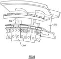
- FIG. 5 illustrates an isometric view, when looking aft, of a heat shield 84 over a strut 72 and a circumferential portion of the diffuser case 62.
- the heat shield 84 is seated in a pocket 83 machined into the lip 81.
- the heat shield 84 and lip 81 may provide a substantially flush surface.
- the heat shield 84 may be attached to the lip 81 using the flanges 82.
- the heat shield 84 may include one or more openings 90 to accommodate bolts or other fasteners in some examples.
- a single heat shield 84 is utilized for a single strut 72, such that there is a 1:1 relationship for heat shields 84 and struts 72 in the example diffuser case 62.
- one heat shield 384 may be designed to cover two or more struts 372.
- Like reference numerals identify corresponding or similar elements throughout the drawings.
- Figure 7 illustrates the example heat shield 84 at the cross section through the radially outer portion 85 shown in Figure 4 .
- the example heat shield 84 includes a nose portion 87 and extension portions 88 extending axially aft from the nose portion 87.
- the nose portion 87 is forward of the leading edge 78 of the strut 72, and the extension portions 88 extend across opposing circumferential sides C1, C2 of the strut 72.
- the example extension portions 88 cover forward surfaces 79A of the circumferential sides C1, C2, but leave aft surfaces 79B of the circumferential sides C1, C2 uncovered.
- the axial length L1 of the uncovered aft surface 79B is 5-90% of the total axial length LT of the strut 72 from the leading edge 78 to the trailing edge 60. In one example, the length L1 is about 85% of the length LT. Leaving the portions 79B uncovered may reduce vibration created by the overhung mass of the heat shield 84.
- An axial length L2 of the heat shield 84 may be 10-80% of the length LT in some examples. In some examples, the length L2 is about 20% of the length LT.
- the example struts 72 are hollow such that they each form an internal cavity 89.
- the leading edge 78 may provide a recess 91 contoured to receive the heat shield 84, such that the heat shield 84 and aft surfaces 79B on each circumferential side C1, C2 of the strut 72 form flush surfaces.
- Figure 8A illustrates an enlarged view (with reference to Figure 7 ) of an example heat shield 184.
- One or more pedestals 192 may extend from an interior surface 194 of the heat shield 184 to form a passageway 193 between the heat shield 184 and the strut 172 and limit direct thermal conductivity between the heat shield 184 and the strut 172.
- the strut 172 may provide pedestals.
- One or more cooling holes 195 may extend from the internal cavity 189 through the outer surface 196 of the strut 172 in some examples, such that the cavity 189 and passageway 193 are in fluid communication.
- Two cooling holes 195 on one side of the strut 172 are shown for illustrative purposes, but more or fewer cooling holes 195 on one or both sides of the strut 172 may be utilized.
- the end of one or both extensions 188 may be spaced from the recess 191 to provide one or more discharges 197 for the passageway 193.
- Figure 8B schematically illustrates an example cooling flow for the example heat shield 184 of Figure 8A .
- the temperature within the cavity 189 is less than the external temperature within the diffusing section, adequate pressure may be applied to the cavity 189 to flow cooling air from the cavity 189 through the cooling holes 195, through the passageway 193, and out the discharge 197, as shown schematically. Additional thermal control may therefore be achieved by active cooling of the heat shield 184 and strut 172 interface.
- a thermal barrier coating 198 may be applied to the interior surface 194 in some examples. Alternatively or additionally, thermal barrier coatings 198 may be utilized on the struts 172 and/or on the exterior surface of 194. In some examples, the thermal barrier coating 198 may be magnesium stabilized zirconium oxide.
- Figure 9 illustrates an example heat shield 284 substantially similar to the heat shield 184 of Figures 7A and 7B.
- the extension portion 288 of the heat shield 284 may include a retention lip 299 received in a slot 300 of the strut 272 to prevent or control relative motion of the edges of extension portion 288.
- the retention lip 299 and/or slot 300 may be intermittent with discontinuous lips and slots and offset radially to allow insertion and fixturing through relative radial motion between components required to overcome the draft angles and geometry shown in Figure 9 .
- the retention lip 299 is shown on one extension 288 in the example for illustrative purposes, one or both of the extension portions 288 may include a retention lip 299 in some examples.
- the example heat shields 84/184/284 help to change the operating metal temperature magnitude and/or time dependent thermal transient response of the struts 72.
- the example heat shields 84/184/284/384 protect against thermal mechanical fatigue of the diffuser case 62, including at the zone 76 of the strut 72 (see Figure 3 ), without having to change the loads applied to the diffuser case 62.
- the heat shields 84/184/284/384 react to the transient temperature of the strut 72.
- the thermal response is slowed and the cyclic stress is reduced during repeated acceleration and deceleration of the engine 20. This reduction in time-dependent stress results in an improvement in local fatigue life at the component life limiting location 76.
- a gas turbine engine 20 may include a high pressure compressor 52 disposed about a central longitudinal axis and a combustor 56.
- a diffuser case 62 includes an outer ring 64 providing a first platform 68 and an inner ring 66 providing a second platform 70. The first platform 68 and the second platform 70 are axially between the high pressure compressor 52 and the combustor 56 with respect to the central longitudinal axis.
- a plurality of circumferentially spaced struts 72 extend radially from the first platform 68 to the second platform 70.
- Each of the plurality of heat shields 84 includes a first extension portion 88 and a second extension portion 88.
- the first extension portion 88 extends aft to a first end
- the second extension portion 88 extends aft to a second end
- the first and second end are spaced axially forward from a trailing edge 60 of the strut 72.
Landscapes
- Engineering & Computer Science (AREA)
- Mechanical Engineering (AREA)
- General Engineering & Computer Science (AREA)
- Chemical & Material Sciences (AREA)
- Materials Engineering (AREA)
- Structures Of Non-Positive Displacement Pumps (AREA)
Claims (15)
- Gasturbinentriebwerk (20), umfassend:einen Hochdruckverdichter (52), welcher um eine Längsmittelachse (A) angeordnet ist;eine Brennkammer (56); undein Diffusorgehäuse (62), welches Folgendes beinhaltet:einen äußeren Ring (64), welcher eine erste Plattform (68) bereitstellt;einen inneren Ring (66), welcher eine zweite Plattform (70) bereitstellt, wobei die erste Plattform (68) und die zweite Plattform (70) axial zwischen dem Hochdruckverdichter (52) und der Brennkammer (56) liegen bezogen auf die Mittellängsachse (A) ;eine Vielzahl von umlaufend beanstandeten Streben (72), welche sich radial von der ersten Plattform (68) zu der zweiten Plattform (70) erstrecken und jeweils eine erste und zweite umlaufende Seite (C1, C2) beinhalten; undeine Vielzahl von Hitzeschilden (84), welche an einer Vorderkante (78) angeordnet sind, welche an einem vorderen Ende einer entsprechenden der Vielzahl von Streben (72) definiert ist;dadurch gekennzeichnet, dass der radiale Abstand an der Vorderkante (78) der Streben (72) von der ersten Plattform (68) zu der zweiten Plattform (70) eine erste radiale Höhe (RT) definiert, und der radiale Abstand von der ersten Plattform (68) zu dem radial äußersten Punkt des Hitzeschilds (84) eine zweite radiale Höhe (R1) ist, und die zweite radiale Höhe (R1) 5-80 % der ersten radialen Höhe (RT) beträgt.
- Gasturbinentriebwerk nach Anspruch 1, wobei jedes der Vielzahl von Hitzeschilden (84) einen ersten Erstreckungsteil (88) und einen zweiten Erstreckungsteil (88) beinhaltet, wobei sich der erste Erstreckungsteil (88) zu einem ersten Ende erstreckt, der zweite Erstreckungsteil (88) zu einem zweiten Ende erstreckt und das erste und zweite Ende axial nach vorn von einer Hinterkante (60) der Strebe (72) axial beabstandet sind.
- Gasturbinentriebwerk nach Anspruch 2, wobei der Abstand von der Hinterkante (60) zu dem ersten Ende eine erste axiale Länge (L1) aufweist, die Vielzahl von Streben (72) jeweils eine zweite axiale Länge (LT) aufweist und die erste axiale Länge (L1) 25-80 % der zweiten axialen Länge (LT) beträgt, optional wobei der Abstand von der Hinterkante (60) zu dem zweiten Ende eine dritte axiale Länge aufweist, und wobei die dritte axiale Länge 25-80 % der zweiten axialen Länge beträgt.
- Gasturbinentriebwerk nach Anspruch 2 oder 3, wobei ein radial äußerer Teil (85) von jedem der Vielzahl von Hitzeschilden (84) einen Nasenteil (87) beinhaltet, wobei sich der erste und zweite Erstreckungsteil (88) von dem Nasenteil (87) nach hinten erstrecken, und wobei der Nasenteil (87) vor der Vorderkante (78) einer entsprechenden der Vielzahl von Streben (72) ist.
- Gasturbinentriebwerk nach einem der vorstehenden Ansprüche, wobei die erste Plattform (68) und die zweite Plattform (70) einen Teil eines Kernströmungswegs (C) des Gasturbinentriebwerks (20) begrenzen.
- Gasturbinentriebwerk nach einem der vorstehenden Ansprüche, wobei der Hochdruckverdichter (52) eine Ausgangsleitschaufel (80) beinhaltet, welche eine erste Leitschaufelplattform (75A) und eine zweite Leitschaufelplattform (75B) beinhaltet, wobei die erste Plattform (68) die erste Leitschaufelplattform (75A) berührt und die zweite Plattform (70) die zweite Leitschaufelplattform (75B) berührt.
- Gasturbinentriebwerk nach einem der vorstehenden Ansprüche, wobei jedes der Vielzahl von Hitzeschilden (84) einen radial inneren Teil (86) beinhaltet, welcher sich so erstreckt, dass er eine Lippe (81) bedeckt, welche sich radial nach innen von der zweiten Plattform (70) erstreckt, optional wobei der radial innere Teil (86) in einer Tasche (83) in der Lippe (81) aufgenommen ist.
- Gasturbinentriebwerk nach einem der vorstehenden Ansprüche, wobei jedes der Vielzahl von Hitzeschilden (84) einen oder den radial äußeren Teil (85) beinhaltet, welcher eine gekrümmte äußere Fläche (77) bereitstellt, optional wobei die gekrümmte äußere Fläche (77) eine konvexe Fläche ist, welche sich nach innen krümmt, wenn sie sich radial nach außen und axial nach hinten erstreckt.
- Gasturbinentriebwerk nach einem der vorstehenden Ansprüche, wobei jede der Vielzahl von Streben (72) einen inneren Hohlraum (89) beinhaltet.
- Gasturbinentriebwerk nach Anspruch 9, wobei mindestens eine der Vielzahl von Hitzeschilden (84) und der Vielzahl von Streben (72) mindestens ein Podest (192) beinhaltet, um mindestens einen Durchgang (193) zwischen jeder der Vielzahl von Hitzeschilden (84) und der Vielzahl von Streben (72) bereitzustellen.
- Gasturbinentriebwerk nach Anspruch 10, wobei der innere Hohlraum (89) und ein entsprechender des mindestens einen Durchgangs (193) durch Kühllöcher (195) in der Vielzahl von Streben (72) in Fluidkommunikation stehen.
- Gasturbinentriebwerk nach einem der vorstehenden Ansprüche, wobei sich eine oder die Lippe (81) von der zweiten Plattform (70) radial nach innen erstreckt und einen ersten Flansch (82) und einen zweiten Flansch (82) bereitstellt, und wobei jede der Vielzahl von Hitzeschilden (84) auf dem ersten Flansch (82) und dem zweiten Flansch (82) angeordnet ist.
- Gasturbinentriebwerk nach einem der vorstehenden Ansprüche, wobei jedes der Vielzahl von Hitzeschilden (84) aus einer Nickellegierung gebildet ist.
- Gasturbinentriebwerk nach einem der vorstehenden Ansprüche, wobei jedes der Vielzahl von Hitzeschilden (84) in einer Vertiefung (91) der entsprechenden der Vielzahl von Streben (72) aufgenommen ist.
- Gasturbinentriebwerk nach einem der vorstehenden Ansprüche, wobei der radial äußerste Punkt des Hitzeschilds (84) radial nach innen von der ersten Plattform (68) an der Vorderkante (78) der Streben (72) ist.
Applications Claiming Priority (1)
| Application Number | Priority Date | Filing Date | Title |
|---|---|---|---|
| US16/213,395 US10927707B2 (en) | 2018-12-07 | 2018-12-07 | Diffuser case heat shields |
Publications (2)
| Publication Number | Publication Date |
|---|---|
| EP3663527A1 EP3663527A1 (de) | 2020-06-10 |
| EP3663527B1 true EP3663527B1 (de) | 2022-01-26 |
Family
ID=68835019
Family Applications (1)
| Application Number | Title | Priority Date | Filing Date |
|---|---|---|---|
| EP19214262.8A Active EP3663527B1 (de) | 2018-12-07 | 2019-12-06 | Diffusorgehäusewärmeabschirmungen |
Country Status (2)
| Country | Link |
|---|---|
| US (1) | US10927707B2 (de) |
| EP (1) | EP3663527B1 (de) |
Families Citing this family (1)
| Publication number | Priority date | Publication date | Assignee | Title |
|---|---|---|---|---|
| US12152502B2 (en) | 2021-10-29 | 2024-11-26 | Pratt & Whitney Canada Corp. | Selectively coated gas path surfaces within a hot section of a gas turbine engine |
Family Cites Families (15)
| Publication number | Priority date | Publication date | Assignee | Title |
|---|---|---|---|---|
| US7003959B2 (en) * | 2002-12-31 | 2006-02-28 | General Electric Company | High temperature splash plate for temperature reduction by optical reflection and process for manufacturing |
| US8083465B2 (en) | 2008-09-05 | 2011-12-27 | United Technologies Corporation | Repaired turbine exhaust strut heat shield vanes and repair methods |
| US8459941B2 (en) * | 2009-06-15 | 2013-06-11 | General Electric Company | Mechanical joint for a gas turbine engine |
| US9528382B2 (en) * | 2009-11-10 | 2016-12-27 | General Electric Company | Airfoil heat shield |
| US9816439B2 (en) | 2011-05-16 | 2017-11-14 | Gkn Aerospace Sweden Ab | Fairing of a gas turbine structure |
| US20140219808A1 (en) * | 2012-10-01 | 2014-08-07 | United Technologies Corporation | Sheath with extended wings |
| WO2014105599A1 (en) | 2012-12-29 | 2014-07-03 | United Technologies Corporation | Heat shield for cooling a strut |
| US10294819B2 (en) * | 2012-12-29 | 2019-05-21 | United Technologies Corporation | Multi-piece heat shield |
| US20150044046A1 (en) | 2013-08-07 | 2015-02-12 | Yevgeniy Shteyman | Manufacturing method for strut shield collar of gas turbine exhaust diffuser |
| US9628382B2 (en) | 2014-02-05 | 2017-04-18 | Intel Corporation | Reliable transport of ethernet packet data with wire-speed and packet data rate match |
| US10287891B2 (en) * | 2014-12-29 | 2019-05-14 | United Technologies Corporation | Radial lock for fan blade sheath |
| FR3045713B1 (fr) * | 2015-12-21 | 2020-09-18 | Snecma | Bouclier de bord d'attaque |
| US10215028B2 (en) * | 2016-03-07 | 2019-02-26 | Rolls-Royce North American Technologies Inc. | Turbine blade with heat shield |
| US20180010457A1 (en) | 2016-07-08 | 2018-01-11 | General Electric Company | Coupon for hot gas path component having manufacturing assist features |
| US20190024513A1 (en) | 2017-07-19 | 2019-01-24 | General Electric Company | Shield for a turbine engine airfoil |
-
2018
- 2018-12-07 US US16/213,395 patent/US10927707B2/en active Active
-
2019
- 2019-12-06 EP EP19214262.8A patent/EP3663527B1/de active Active
Also Published As
| Publication number | Publication date |
|---|---|
| US10927707B2 (en) | 2021-02-23 |
| US20200182088A1 (en) | 2020-06-11 |
| EP3663527A1 (de) | 2020-06-10 |
Similar Documents
| Publication | Publication Date | Title |
|---|---|---|
| US11781440B2 (en) | Scalloped mateface seal arrangement for CMC platforms | |
| EP3734018B1 (de) | Dichtung für ein gasturbinentriebwerks-bauteil und zugehöriges verfahren | |
| EP2964934B1 (de) | Gasturbinenmotorkomponente mit einem federdichtungsschlitz von variabler breite | |
| US11661865B2 (en) | Gas turbine engine component | |
| EP4067622B1 (de) | Cmc-komponentenströmungsablöserflansche | |
| EP3034794B1 (de) | Wand eines bauteils eines gasturbinenkraftwerks und zugehöriges bauteil | |
| EP3066318B1 (de) | Innendiffusorgehäuse für einen gasturbinenmotor | |
| EP3587740B1 (de) | Dichtungsanordnung für ein gasturbinentriebwerk und montageverfahren | |
| EP3546704B1 (de) | Turboluftstrahltriebwerksgehäuse mit lagergehäuse | |
| EP2912290B1 (de) | Hochdruckkompressor mit gekühlten gehäuseflanschen | |
| EP3663527B1 (de) | Diffusorgehäusewärmeabschirmungen | |
| EP3192976B1 (de) | Gasturbinentriebwerkskomponente, zugehörige äussere laufschaufelluftdichtung und gasturbinentriebwerk | |
| EP3623587B1 (de) | Schaufelprofilanordnug für ein gasturbinentriebwerk | |
| EP4086434A2 (de) | Cmc-schaufel mit plattform-abdeckung | |
| EP3748131B1 (de) | Anordnung zur strömungslenkung von einer äussere laufschaufelluftdichtung (boas) | |
| EP3023596B1 (de) | Innengekühlte turbinenplattform | |
| EP3611352B1 (de) | Befestigungsblock für die äussere luftdichtung einer schaufel mit konvektionskühlung | |
| EP3620611B1 (de) | Einheitlicher boas-träger und schaufelplattform | |
| EP2890878B1 (de) | Aussenluftdichtung für eine turbinenschaufel | |
| EP3597870B1 (de) | Gasturbine | |
| EP3406851B1 (de) | Komponente für ein gasturbinentriebwerk und verfahren zum herstellen einer kernanordnung | |
| EP3556997B1 (de) | Schaufel mit einlassöffnung an der hinteren seite der wurzel |
Legal Events
| Date | Code | Title | Description |
|---|---|---|---|
| PUAI | Public reference made under article 153(3) epc to a published international application that has entered the european phase |
Free format text: ORIGINAL CODE: 0009012 |
|
| STAA | Information on the status of an ep patent application or granted ep patent |
Free format text: STATUS: THE APPLICATION HAS BEEN PUBLISHED |
|
| AK | Designated contracting states |
Kind code of ref document: A1 Designated state(s): AL AT BE BG CH CY CZ DE DK EE ES FI FR GB GR HR HU IE IS IT LI LT LU LV MC MK MT NL NO PL PT RO RS SE SI SK SM TR |
|
| AX | Request for extension of the european patent |
Extension state: BA ME |
|
| STAA | Information on the status of an ep patent application or granted ep patent |
Free format text: STATUS: REQUEST FOR EXAMINATION WAS MADE |
|
| 17P | Request for examination filed |
Effective date: 20201209 |
|
| RBV | Designated contracting states (corrected) |
Designated state(s): AL AT BE BG CH CY CZ DE DK EE ES FI FR GB GR HR HU IE IS IT LI LT LU LV MC MK MT NL NO PL PT RO RS SE SI SK SM TR |
|
| RAP1 | Party data changed (applicant data changed or rights of an application transferred) |
Owner name: RAYTHEON TECHNOLOGIES CORPORATION |
|
| RIC1 | Information provided on ipc code assigned before grant |
Ipc: F01D 5/28 20060101AFI20210426BHEP Ipc: F01D 9/04 20060101ALI20210426BHEP Ipc: F01D 25/16 20060101ALI20210426BHEP Ipc: F01D 5/14 20060101ALN20210426BHEP |
|
| GRAP | Despatch of communication of intention to grant a patent |
Free format text: ORIGINAL CODE: EPIDOSNIGR1 |
|
| STAA | Information on the status of an ep patent application or granted ep patent |
Free format text: STATUS: GRANT OF PATENT IS INTENDED |
|
| RIC1 | Information provided on ipc code assigned before grant |
Ipc: F01D 5/28 20060101AFI20210628BHEP Ipc: F01D 9/04 20060101ALI20210628BHEP Ipc: F01D 25/16 20060101ALI20210628BHEP Ipc: F01D 5/14 20060101ALN20210628BHEP |
|
| INTG | Intention to grant announced |
Effective date: 20210712 |
|
| GRAS | Grant fee paid |
Free format text: ORIGINAL CODE: EPIDOSNIGR3 |
|
| GRAA | (expected) grant |
Free format text: ORIGINAL CODE: 0009210 |
|
| STAA | Information on the status of an ep patent application or granted ep patent |
Free format text: STATUS: THE PATENT HAS BEEN GRANTED |
|
| AK | Designated contracting states |
Kind code of ref document: B1 Designated state(s): AL AT BE BG CH CY CZ DE DK EE ES FI FR GB GR HR HU IE IS IT LI LT LU LV MC MK MT NL NO PL PT RO RS SE SI SK SM TR |
|
| REG | Reference to a national code |
Ref country code: GB Ref legal event code: FG4D |
|
| REG | Reference to a national code |
Ref country code: CH Ref legal event code: EP |
|
| REG | Reference to a national code |
Ref country code: AT Ref legal event code: REF Ref document number: 1465444 Country of ref document: AT Kind code of ref document: T Effective date: 20220215 |
|
| REG | Reference to a national code |
Ref country code: IE Ref legal event code: FG4D |
|
| REG | Reference to a national code |
Ref country code: DE Ref legal event code: R096 Ref document number: 602019011207 Country of ref document: DE |
|
| REG | Reference to a national code |
Ref country code: LT Ref legal event code: MG9D |
|
| REG | Reference to a national code |
Ref country code: NL Ref legal event code: MP Effective date: 20220126 |
|
| REG | Reference to a national code |
Ref country code: AT Ref legal event code: MK05 Ref document number: 1465444 Country of ref document: AT Kind code of ref document: T Effective date: 20220126 |
|
| PG25 | Lapsed in a contracting state [announced via postgrant information from national office to epo] |
Ref country code: NL Free format text: LAPSE BECAUSE OF FAILURE TO SUBMIT A TRANSLATION OF THE DESCRIPTION OR TO PAY THE FEE WITHIN THE PRESCRIBED TIME-LIMIT Effective date: 20220126 |
|
| PG25 | Lapsed in a contracting state [announced via postgrant information from national office to epo] |
Ref country code: SE Free format text: LAPSE BECAUSE OF FAILURE TO SUBMIT A TRANSLATION OF THE DESCRIPTION OR TO PAY THE FEE WITHIN THE PRESCRIBED TIME-LIMIT Effective date: 20220126 Ref country code: RS Free format text: LAPSE BECAUSE OF FAILURE TO SUBMIT A TRANSLATION OF THE DESCRIPTION OR TO PAY THE FEE WITHIN THE PRESCRIBED TIME-LIMIT Effective date: 20220126 Ref country code: PT Free format text: LAPSE BECAUSE OF FAILURE TO SUBMIT A TRANSLATION OF THE DESCRIPTION OR TO PAY THE FEE WITHIN THE PRESCRIBED TIME-LIMIT Effective date: 20220526 Ref country code: NO Free format text: LAPSE BECAUSE OF FAILURE TO SUBMIT A TRANSLATION OF THE DESCRIPTION OR TO PAY THE FEE WITHIN THE PRESCRIBED TIME-LIMIT Effective date: 20220426 Ref country code: LT Free format text: LAPSE BECAUSE OF FAILURE TO SUBMIT A TRANSLATION OF THE DESCRIPTION OR TO PAY THE FEE WITHIN THE PRESCRIBED TIME-LIMIT Effective date: 20220126 Ref country code: HR Free format text: LAPSE BECAUSE OF FAILURE TO SUBMIT A TRANSLATION OF THE DESCRIPTION OR TO PAY THE FEE WITHIN THE PRESCRIBED TIME-LIMIT Effective date: 20220126 Ref country code: ES Free format text: LAPSE BECAUSE OF FAILURE TO SUBMIT A TRANSLATION OF THE DESCRIPTION OR TO PAY THE FEE WITHIN THE PRESCRIBED TIME-LIMIT Effective date: 20220126 Ref country code: BG Free format text: LAPSE BECAUSE OF FAILURE TO SUBMIT A TRANSLATION OF THE DESCRIPTION OR TO PAY THE FEE WITHIN THE PRESCRIBED TIME-LIMIT Effective date: 20220426 |
|
| PG25 | Lapsed in a contracting state [announced via postgrant information from national office to epo] |
Ref country code: PL Free format text: LAPSE BECAUSE OF FAILURE TO SUBMIT A TRANSLATION OF THE DESCRIPTION OR TO PAY THE FEE WITHIN THE PRESCRIBED TIME-LIMIT Effective date: 20220126 Ref country code: LV Free format text: LAPSE BECAUSE OF FAILURE TO SUBMIT A TRANSLATION OF THE DESCRIPTION OR TO PAY THE FEE WITHIN THE PRESCRIBED TIME-LIMIT Effective date: 20220126 Ref country code: GR Free format text: LAPSE BECAUSE OF FAILURE TO SUBMIT A TRANSLATION OF THE DESCRIPTION OR TO PAY THE FEE WITHIN THE PRESCRIBED TIME-LIMIT Effective date: 20220427 Ref country code: FI Free format text: LAPSE BECAUSE OF FAILURE TO SUBMIT A TRANSLATION OF THE DESCRIPTION OR TO PAY THE FEE WITHIN THE PRESCRIBED TIME-LIMIT Effective date: 20220126 Ref country code: AT Free format text: LAPSE BECAUSE OF FAILURE TO SUBMIT A TRANSLATION OF THE DESCRIPTION OR TO PAY THE FEE WITHIN THE PRESCRIBED TIME-LIMIT Effective date: 20220126 |
|
| PG25 | Lapsed in a contracting state [announced via postgrant information from national office to epo] |
Ref country code: IS Free format text: LAPSE BECAUSE OF FAILURE TO SUBMIT A TRANSLATION OF THE DESCRIPTION OR TO PAY THE FEE WITHIN THE PRESCRIBED TIME-LIMIT Effective date: 20220526 |
|
| REG | Reference to a national code |
Ref country code: DE Ref legal event code: R097 Ref document number: 602019011207 Country of ref document: DE |
|
| PG25 | Lapsed in a contracting state [announced via postgrant information from national office to epo] |
Ref country code: SM Free format text: LAPSE BECAUSE OF FAILURE TO SUBMIT A TRANSLATION OF THE DESCRIPTION OR TO PAY THE FEE WITHIN THE PRESCRIBED TIME-LIMIT Effective date: 20220126 Ref country code: SK Free format text: LAPSE BECAUSE OF FAILURE TO SUBMIT A TRANSLATION OF THE DESCRIPTION OR TO PAY THE FEE WITHIN THE PRESCRIBED TIME-LIMIT Effective date: 20220126 Ref country code: RO Free format text: LAPSE BECAUSE OF FAILURE TO SUBMIT A TRANSLATION OF THE DESCRIPTION OR TO PAY THE FEE WITHIN THE PRESCRIBED TIME-LIMIT Effective date: 20220126 Ref country code: EE Free format text: LAPSE BECAUSE OF FAILURE TO SUBMIT A TRANSLATION OF THE DESCRIPTION OR TO PAY THE FEE WITHIN THE PRESCRIBED TIME-LIMIT Effective date: 20220126 Ref country code: DK Free format text: LAPSE BECAUSE OF FAILURE TO SUBMIT A TRANSLATION OF THE DESCRIPTION OR TO PAY THE FEE WITHIN THE PRESCRIBED TIME-LIMIT Effective date: 20220126 Ref country code: CZ Free format text: LAPSE BECAUSE OF FAILURE TO SUBMIT A TRANSLATION OF THE DESCRIPTION OR TO PAY THE FEE WITHIN THE PRESCRIBED TIME-LIMIT Effective date: 20220126 |
|
| PG25 | Lapsed in a contracting state [announced via postgrant information from national office to epo] |
Ref country code: AL Free format text: LAPSE BECAUSE OF FAILURE TO SUBMIT A TRANSLATION OF THE DESCRIPTION OR TO PAY THE FEE WITHIN THE PRESCRIBED TIME-LIMIT Effective date: 20220126 |
|
| PLBE | No opposition filed within time limit |
Free format text: ORIGINAL CODE: 0009261 |
|
| STAA | Information on the status of an ep patent application or granted ep patent |
Free format text: STATUS: NO OPPOSITION FILED WITHIN TIME LIMIT |
|
| 26N | No opposition filed |
Effective date: 20221027 |
|
| PG25 | Lapsed in a contracting state [announced via postgrant information from national office to epo] |
Ref country code: SI Free format text: LAPSE BECAUSE OF FAILURE TO SUBMIT A TRANSLATION OF THE DESCRIPTION OR TO PAY THE FEE WITHIN THE PRESCRIBED TIME-LIMIT Effective date: 20220126 |
|
| P01 | Opt-out of the competence of the unified patent court (upc) registered |
Effective date: 20230521 |
|
| PG25 | Lapsed in a contracting state [announced via postgrant information from national office to epo] |
Ref country code: IT Free format text: LAPSE BECAUSE OF FAILURE TO SUBMIT A TRANSLATION OF THE DESCRIPTION OR TO PAY THE FEE WITHIN THE PRESCRIBED TIME-LIMIT Effective date: 20220126 |
|
| REG | Reference to a national code |
Ref country code: CH Ref legal event code: PL |
|
| REG | Reference to a national code |
Ref country code: BE Ref legal event code: MM Effective date: 20221231 |
|
| PG25 | Lapsed in a contracting state [announced via postgrant information from national office to epo] |
Ref country code: LU Free format text: LAPSE BECAUSE OF NON-PAYMENT OF DUE FEES Effective date: 20221206 |
|
| PG25 | Lapsed in a contracting state [announced via postgrant information from national office to epo] |
Ref country code: LI Free format text: LAPSE BECAUSE OF NON-PAYMENT OF DUE FEES Effective date: 20221231 Ref country code: IE Free format text: LAPSE BECAUSE OF NON-PAYMENT OF DUE FEES Effective date: 20221206 Ref country code: CH Free format text: LAPSE BECAUSE OF NON-PAYMENT OF DUE FEES Effective date: 20221231 |
|
| PG25 | Lapsed in a contracting state [announced via postgrant information from national office to epo] |
Ref country code: BE Free format text: LAPSE BECAUSE OF NON-PAYMENT OF DUE FEES Effective date: 20221231 |
|
| PG25 | Lapsed in a contracting state [announced via postgrant information from national office to epo] |
Ref country code: HU Free format text: LAPSE BECAUSE OF FAILURE TO SUBMIT A TRANSLATION OF THE DESCRIPTION OR TO PAY THE FEE WITHIN THE PRESCRIBED TIME-LIMIT; INVALID AB INITIO Effective date: 20191206 |
|
| PG25 | Lapsed in a contracting state [announced via postgrant information from national office to epo] |
Ref country code: CY Free format text: LAPSE BECAUSE OF FAILURE TO SUBMIT A TRANSLATION OF THE DESCRIPTION OR TO PAY THE FEE WITHIN THE PRESCRIBED TIME-LIMIT Effective date: 20220126 |
|
| PG25 | Lapsed in a contracting state [announced via postgrant information from national office to epo] |
Ref country code: MK Free format text: LAPSE BECAUSE OF FAILURE TO SUBMIT A TRANSLATION OF THE DESCRIPTION OR TO PAY THE FEE WITHIN THE PRESCRIBED TIME-LIMIT Effective date: 20220126 |
|
| PG25 | Lapsed in a contracting state [announced via postgrant information from national office to epo] |
Ref country code: MC Free format text: LAPSE BECAUSE OF FAILURE TO SUBMIT A TRANSLATION OF THE DESCRIPTION OR TO PAY THE FEE WITHIN THE PRESCRIBED TIME-LIMIT Effective date: 20220126 |
|
| PG25 | Lapsed in a contracting state [announced via postgrant information from national office to epo] |
Ref country code: TR Free format text: LAPSE BECAUSE OF FAILURE TO SUBMIT A TRANSLATION OF THE DESCRIPTION OR TO PAY THE FEE WITHIN THE PRESCRIBED TIME-LIMIT Effective date: 20220126 Ref country code: MC Free format text: LAPSE BECAUSE OF FAILURE TO SUBMIT A TRANSLATION OF THE DESCRIPTION OR TO PAY THE FEE WITHIN THE PRESCRIBED TIME-LIMIT Effective date: 20220126 |
|
| PG25 | Lapsed in a contracting state [announced via postgrant information from national office to epo] |
Ref country code: MT Free format text: LAPSE BECAUSE OF FAILURE TO SUBMIT A TRANSLATION OF THE DESCRIPTION OR TO PAY THE FEE WITHIN THE PRESCRIBED TIME-LIMIT Effective date: 20220126 |
|
| REG | Reference to a national code |
Ref country code: DE Ref legal event code: R081 Ref document number: 602019011207 Country of ref document: DE Owner name: RTX CORPORATION (N.D.GES.D. STAATES DELAWARE),, US Free format text: FORMER OWNER: RAYTHEON TECHNOLOGIES CORPORATION, FARMINGTON, CT, US |
|
| PGFP | Annual fee paid to national office [announced via postgrant information from national office to epo] |
Ref country code: DE Payment date: 20251126 Year of fee payment: 7 |
|
| PGFP | Annual fee paid to national office [announced via postgrant information from national office to epo] |
Ref country code: GB Payment date: 20251119 Year of fee payment: 7 |
|
| PGFP | Annual fee paid to national office [announced via postgrant information from national office to epo] |
Ref country code: FR Payment date: 20251120 Year of fee payment: 7 |