EP3663521B1 - Subsonic swept fan blade - Google Patents
Subsonic swept fan blade Download PDFInfo
- Publication number
- EP3663521B1 EP3663521B1 EP20151427.0A EP20151427A EP3663521B1 EP 3663521 B1 EP3663521 B1 EP 3663521B1 EP 20151427 A EP20151427 A EP 20151427A EP 3663521 B1 EP3663521 B1 EP 3663521B1
- Authority
- EP
- European Patent Office
- Prior art keywords
- span
- sweep
- propulsor
- radial
- spool
- Prior art date
- Legal status (The legal status is an assumption and is not a legal conclusion. Google has not performed a legal analysis and makes no representation as to the accuracy of the status listed.)
- Active
Links
- 230000007704 transition Effects 0.000 claims description 8
- 230000007423 decrease Effects 0.000 claims description 2
- 230000001141 propulsive effect Effects 0.000 description 3
- 230000035939 shock Effects 0.000 description 2
- 230000001154 acute effect Effects 0.000 description 1
- 230000008859 change Effects 0.000 description 1
- 230000006835 compression Effects 0.000 description 1
- 238000007906 compression Methods 0.000 description 1
- 239000012530 fluid Substances 0.000 description 1
- 239000000446 fuel Substances 0.000 description 1
- 230000002427 irreversible effect Effects 0.000 description 1
- 230000004048 modification Effects 0.000 description 1
- 238000012986 modification Methods 0.000 description 1
- 230000010399 physical interaction Effects 0.000 description 1
- 230000009467 reduction Effects 0.000 description 1
- 230000004044 response Effects 0.000 description 1
- 230000003068 static effect Effects 0.000 description 1
Images


Classifications
-
- F—MECHANICAL ENGINEERING; LIGHTING; HEATING; WEAPONS; BLASTING
- F01—MACHINES OR ENGINES IN GENERAL; ENGINE PLANTS IN GENERAL; STEAM ENGINES
- F01D—NON-POSITIVE DISPLACEMENT MACHINES OR ENGINES, e.g. STEAM TURBINES
- F01D5/00—Blades; Blade-carrying members; Heating, heat-insulating, cooling or antivibration means on the blades or the members
- F01D5/12—Blades
- F01D5/14—Form or construction
- F01D5/141—Shape, i.e. outer, aerodynamic form
-
- F—MECHANICAL ENGINEERING; LIGHTING; HEATING; WEAPONS; BLASTING
- F05—INDEXING SCHEMES RELATING TO ENGINES OR PUMPS IN VARIOUS SUBCLASSES OF CLASSES F01-F04
- F05D—INDEXING SCHEME FOR ASPECTS RELATING TO NON-POSITIVE-DISPLACEMENT MACHINES OR ENGINES, GAS-TURBINES OR JET-PROPULSION PLANTS
- F05D2220/00—Application
- F05D2220/30—Application in turbines
- F05D2220/36—Application in turbines specially adapted for the fan of turbofan engines
-
- F—MECHANICAL ENGINEERING; LIGHTING; HEATING; WEAPONS; BLASTING
- F05—INDEXING SCHEMES RELATING TO ENGINES OR PUMPS IN VARIOUS SUBCLASSES OF CLASSES F01-F04
- F05D—INDEXING SCHEME FOR ASPECTS RELATING TO NON-POSITIVE-DISPLACEMENT MACHINES OR ENGINES, GAS-TURBINES OR JET-PROPULSION PLANTS
- F05D2240/00—Components
- F05D2240/20—Rotors
- F05D2240/30—Characteristics of rotor blades, i.e. of any element transforming dynamic fluid energy to or from rotational energy and being attached to a rotor
- F05D2240/302—Characteristics of rotor blades, i.e. of any element transforming dynamic fluid energy to or from rotational energy and being attached to a rotor characteristics related to shock waves, transonic or supersonic flow
-
- F—MECHANICAL ENGINEERING; LIGHTING; HEATING; WEAPONS; BLASTING
- F05—INDEXING SCHEMES RELATING TO ENGINES OR PUMPS IN VARIOUS SUBCLASSES OF CLASSES F01-F04
- F05D—INDEXING SCHEME FOR ASPECTS RELATING TO NON-POSITIVE-DISPLACEMENT MACHINES OR ENGINES, GAS-TURBINES OR JET-PROPULSION PLANTS
- F05D2240/00—Components
- F05D2240/20—Rotors
- F05D2240/30—Characteristics of rotor blades, i.e. of any element transforming dynamic fluid energy to or from rotational energy and being attached to a rotor
- F05D2240/303—Characteristics of rotor blades, i.e. of any element transforming dynamic fluid energy to or from rotational energy and being attached to a rotor related to the leading edge of a rotor blade
-
- Y—GENERAL TAGGING OF NEW TECHNOLOGICAL DEVELOPMENTS; GENERAL TAGGING OF CROSS-SECTIONAL TECHNOLOGIES SPANNING OVER SEVERAL SECTIONS OF THE IPC; TECHNICAL SUBJECTS COVERED BY FORMER USPC CROSS-REFERENCE ART COLLECTIONS [XRACs] AND DIGESTS
- Y02—TECHNOLOGIES OR APPLICATIONS FOR MITIGATION OR ADAPTATION AGAINST CLIMATE CHANGE
- Y02T—CLIMATE CHANGE MITIGATION TECHNOLOGIES RELATED TO TRANSPORTATION
- Y02T50/00—Aeronautics or air transport
- Y02T50/60—Efficient propulsion technologies, e.g. for aircraft
Definitions
- This disclosure relates to gas turbine engines and, more particularly, to an engine having a geared turbofan architecture that is designed to operate with a high bypass ratio and a low pressure ratio.
- the propulsive efficiency of a gas turbine engine depends on many different factors, such as the design of the engine and the resulting performance debits on the fan that propels the engine.
- the fan rotates at a high rate of speed such that air passes over at least the outer portion of the blades at transonic or supersonic speeds.
- the fast-moving air creates flow discontinuities or shocks that result in irreversible propulsive losses.
- physical interaction between the fan and the air causes downstream turbulence and further losses.
- the present invention provides a gas turbine engine as set forth in claim 1.
- the fan e.g., propulsor
- the fan rotates at a high rate in the relative frame of reference. Particularly in the outboard region of the fan blades, the air passes over the blades at supersonic speed and creates flow shocks that result in efficiency losses.
- the blades are designed with a swept profile to reduce the air speed closer to the speed of sound.
- the air speed over the blades remains supersonic, or transonic at best, in engine architectures where the turbine of the engine directly drives the fan at the same angular speed as the turbine.
- a disclosed gas turbine engine 20 incorporates a geared architecture and a propulsor 42 with blades 74 that are designed with a swept profile that generates subsonic air speeds over the entire span of the propulsor blades 74, where the same blades, if unswept, would generate transonic or supersonic air speeds over at least a portion of the span.
- FIG. 1 schematically illustrates the gas turbine engine 20.
- the gas turbine engine 20 may be a two-spool turbofan that generally incorporates a fan section 22, a compressor section 24, a combustor section 26 and a turbine section 28. Although depicted as a turbofan gas turbine engine, it is to be understood that the concepts described herein are not limited to use with the disclosed arrangement. Alternative engine architectures may include a single-spool design, a three-spool design, or an open rotor design, among other systems or features.
- the fan section 22 drives air along a bypass flow passage B while the compressor section 24 drives air along a core flow passage C for compression and communication into the combustor section 26.
- the engine 20 includes a low speed spool 30 and high speed spool 32 mounted for rotation about an engine central longitudinal axis A relative to an engine static structure 36 via several bearing systems 38.
- the fan section 22 and the compressor section 24 are concentric with the engine central longitudinal axis A.
- the low speed spool 30 generally includes an inner shaft 40 that is coupled with the propulsor 42, a low pressure compressor 44 and a low pressure turbine 46.
- the low pressure turbine 46 drives the propulsor 42 through the inner shaft 40 and a gear assembly 48, which allows the low speed spool 30 to drive the propulsor 42 at a different (e.g. lower) angular speed.
- the lower speed allows the propulsor blades 74 to be designed with a different sweep profile than would be used for other engine architectures that do not employ a geared architecture, to achieve subsonic flow along the entire blade span.
- the high speed spool 32 includes an outer shaft 50 that is coupled with a high pressure compressor 52 and a high pressure turbine 54.
- a combustor 56 is arranged between the high pressure compressor 52 and the high pressure turbine 54.
- the inner shaft 40 and the outer shaft 50 are concentric and rotate about the engine central longitudinal axis A, which is collinear with their longitudinal axes.
- a core airflow in core flow passage C is compressed in the low pressure compressor 44 then the high pressure compressor 52, mixed with the fuel and burned in the combustor 56, and then expanded over the high pressure turbine 54 and low pressure turbine 46.
- the turbines 54, 46 rotationally drive the respective low speed spool 30 and high speed spool 32 in response to the expansion.
- the propulsor 42 is arranged at an inlet 60 of the bypass flow passage B and the core flow passage C. Air flow through the bypass air passage B exits the engine 20 through an outlet 62 or nozzle.
- the inlet 60 and the outlet 62 establish a design pressure ratio with regard to an inlet pressure at the inlet 60 and an outlet pressure at the outlet 62 of the bypass flow passage B.
- the design pressure ratio may be determined based upon the stagnation inlet pressure and the stagnation outlet pressure at a design rotational speed of the engine 20.
- the engine 20 may optionally include a variable area nozzle 64 within the bypass flow passage B.
- the variable area nozzle 64 is operative to change a cross-sectional area 66 of the outlet 62 to thereby control the pressure ratio via changing pressure within the bypass flow passage B.
- the design pressure ratio may be defined with the variable area nozzle 64 fully open or fully closed.
- the propulsor 42 which in this example is a fan, includes a rotor 70 having a row 72 of propulsor blades 74 that extend circumferentially around a hub 76.
- Each of the propulsor blades 74 includes an airfoil body that extends in a radial span 75 ( Figure 1 ) from a hub 76 between a root 78 and a tip 80, in a chord direction (axially and circumferentially) between a leading edge 82 and a trailing edge 84 and in a thickness direction between a pressure side P and a suction side S.
- chord dimension (CD) is a straight line that extends between the leading edge 82 and the trailing edge 84 of the propulsor blade 74.
- the chord dimension (CD) may vary along the span of the propulsor blade 74.
- the row 72 of propulsor blades 74 also defines a circumferential pitch (CP) that is equivalent to the arc distance between the tips 80 of neighboring propulsor blades 74.
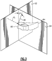
- Figure 3 shows a portion of one of the propulsor blades 74 to describe a swept profile (e.g., Figure 1 , swept profile 77) and sweep angle.
- a design speed of the propulsor 42 such as full throttle, the propulsor 42 receives a working gas (e.g., air).
- the design speed may be determined in a known manner based on the design of the engine 20.
- the axial velocity of the incoming air is substantially constant across the span 75.
- the linear velocity of the rotating propulsor blade 74 increases from the root 78 to the tip 80.
- a component of a relative velocity vector Vr of the air that is normal to the leading edge 82 increases from the root 78 to the tip 80 and, at high enough rotational speeds for an unswept blade, can be supersonic.
- a sweep angle ⁇ at any arbitrary position along the span 75 is the acute angle between a line 90 tangent to the leading edge 82 and a plane 92 perpendicular to the component of the relative velocity vector Vr that is normal to the leading edge 82.
- the sweep angle ⁇ is measured in plane 94, which includes both the component of the relative velocity vector Vr that is normal to the leading edge 82 and the tangent line 90 and is perpendicular to plane 92.
- the propulsor blades 74 have a swept profile such that, at the design speed, the component of the relative velocity vector Vr that is normal to the leading edge 82 is subsonic along the entire radial span 75.
- Figure 4A shows an example swept profile of sweep angle ⁇ versus percent span
- Figure 4B shows the Mach Number of the component of the relative velocity vector Vr that is normal to the leading edge 82 for the profile of Figure 4A .
- the left side of 0% span is at the root 78 and the right side at 100% span is at the tip 80.
- the swept profile has a rearward sweep from 0% to at least 50% of the radial span.
- the sweep angle ⁇ decreases from 0% to at least 50% of the radial span and is less than 15°.
- the swept profile also has a forward sweep from at least 60% to 100% of the radial span.
- the swept profile has a single, exclusive transition 96 between the rearward sweep and the forward sweep from 0% to 100% of the radial span. The transition is between 55% and 60% of the span.
- the amount of rearward sweep may be represented as a percentage SREAR of the total radial span and the amount of forward sweep may be represented as a percentage SFOR of the total radial span.
- a ratio of SREAR / SFOR (SREAR divided by SFOR) is between 1.25 and 1.30.
- Each of SREAR and SFOR is between 55% and 60% such that SREAR plus SFOR equals 100%.
- Figure 5A (outside the wording of the claims) shows another example swept profile of sweep angle ⁇ versus percent span to achieve subsonic flow along the entire radial span 75
- Figure 5B (outside the wording of the claims) shows the Mach Number of the component of the relative velocity vector Vr that is normal to the leading edge 82 for the profile of Figure 5A
- the swept profile has three, exclusive transitions between rearward sweep and forward sweep from 0% to 100% of the radial span. For instance, moving from the 0% at the root 78 toward 100% at the tip 80, the three transitions include two transitions 98 from rearward sweep to forward sweep and one transition 100 from forward sweep to rearward sweep.
- Additional embodiments of the propulsor blades 74 may also include some or all of the below-described properties in combination with the disclosed sweep profile for achieving a subsonic blade.
- the propulsor 42 may include a number (N) of the propulsor blades 74 in the row 72 that is no more than 20.
- the number N may be any number from 10 to 20.
- the propulsor blades 74 define a solidity value with regard to the chord dimension CD at the tips 80 and the circumferential pitch CP.
- the solidity value is defined as a ratio (R) of CD/CP (i.e., CD divided by CP).
- the solidity value of the propulsor 42 is between 0.6 and 1.3.
- the engine 20 may also be designed with a particular design pressure ratio.
- the design pressure ratio may be between 1.1 and 1.55.
- the engine 20 may also be designed with a particular bypass ratio with regard to the amount of air that passes through the bypass flow passage B and the amount of air that passes through the core flow passage C.
- the design bypass ratio of the engine 20 may nominally be 12 or greater.
- the propulsor 42 also defines a ratio of N/R.
- the ratio N/R is between 8 and 28.
- Tables 1 and 2 below show additional examples of solidity and the ratio N/R for different numbers of propulsor blades 74 that can be used with the disclosed sweep profile.
- the disclosed ratios of N/R also enhance the propulsive efficiency of the disclosed engine 20.
- the disclosed ratios of N/R are designed for the geared turbofan architecture of the engine 20 that utilizes the gear assembly 48. That is, the gear assembly 48 allows the propulsor 42 to rotate at a different, lower speed than the low speed spool 30.
- the propulsor 42 can be designed with a large diameter and rotate at a relatively slow speed with regard to the low speed spool 30.
- a relatively low speed, relatively large diameter, and the geometry that permits the disclosed ratios of N/R contribute to the reduction of performance debits, such as by lowering the speed of the air or fluid that passes over the propulsor blades 74.
Description
- This disclosure relates to gas turbine engines and, more particularly, to an engine having a geared turbofan architecture that is designed to operate with a high bypass ratio and a low pressure ratio.
- The propulsive efficiency of a gas turbine engine depends on many different factors, such as the design of the engine and the resulting performance debits on the fan that propels the engine. As an example, the fan rotates at a high rate of speed such that air passes over at least the outer portion of the blades at transonic or supersonic speeds. The fast-moving air creates flow discontinuities or shocks that result in irreversible propulsive losses. Additionally, physical interaction between the fan and the air causes downstream turbulence and further losses. Although some basic principles behind such losses are understood, identifying and changing appropriate design factors to reduce such losses for a given engine architecture has proven to be a complex and elusive task. A gas turbine engine having the features of the preamble of claim 1 is disclosed in
EP1111188 . - The present invention provides a gas turbine engine as set forth in claim 1.
- The various features and advantages of the disclosed examples will become apparent to those skilled in the art from the following detailed description. The drawings that accompany the detailed description can be briefly described as follows.
-
Figure 1 is a schematic cross-section of a gas turbine engine. -
Figure 2 is a perspective view of a fan section of the engine ofFigure 1 . -
Figure 3 is a schematic view of a portion of a propulsor blade to describe a swept profile and sweep angle. -
Figure 4A shows a profile of sweep angle versus percent span. -
Figure 4B shows a profile of Mach number of a component of a relative velocity vector Vr of air that is normal to the leading edge versus percent span for the profile ofFigure 4A . -
Figure 5A (outside the wording of the claims) shows a profile of sweep angle versus percent span. -
Figure 5B (outside the wording of the claims) shows a profile of Mach number of a component of a relative velocity vector Vr of air that is normal to the leading edge versus percent span for the profile ofFigure 5A . - In a turbofan engine, the fan (e.g., propulsor) rotates at a high rate in the relative frame of reference. Particularly in the outboard region of the fan blades, the air passes over the blades at supersonic speed and creates flow shocks that result in efficiency losses. In a turbofan engine architecture where the turbine of the engine directly drives the fan at the same angular speed as the turbine, the blades are designed with a swept profile to reduce the air speed closer to the speed of sound. However, because of the high speed fan rotation, the air speed over the blades remains supersonic, or transonic at best, in engine architectures where the turbine of the engine directly drives the fan at the same angular speed as the turbine.
- As will be described, a disclosed
gas turbine engine 20 incorporates a geared architecture and apropulsor 42 with blades 74 that are designed with a swept profile that generates subsonic air speeds over the entire span of the propulsor blades 74, where the same blades, if unswept, would generate transonic or supersonic air speeds over at least a portion of the span. -
Figure 1 schematically illustrates thegas turbine engine 20. Thegas turbine engine 20 may be a two-spool turbofan that generally incorporates afan section 22, acompressor section 24, acombustor section 26 and aturbine section 28. Although depicted as a turbofan gas turbine engine, it is to be understood that the concepts described herein are not limited to use with the disclosed arrangement. Alternative engine architectures may include a single-spool design, a three-spool design, or an open rotor design, among other systems or features. - The
fan section 22 drives air along a bypass flow passage B while thecompressor section 24 drives air along a core flow passage C for compression and communication into thecombustor section 26. Theengine 20 includes alow speed spool 30 andhigh speed spool 32 mounted for rotation about an engine central longitudinal axis A relative to an enginestatic structure 36 viaseveral bearing systems 38. Thefan section 22 and thecompressor section 24 are concentric with the engine central longitudinal axis A. - The
low speed spool 30 generally includes aninner shaft 40 that is coupled with thepropulsor 42, alow pressure compressor 44 and alow pressure turbine 46. Thelow pressure turbine 46 drives thepropulsor 42 through theinner shaft 40 and agear assembly 48, which allows thelow speed spool 30 to drive thepropulsor 42 at a different (e.g. lower) angular speed. The lower speed allows the propulsor blades 74 to be designed with a different sweep profile than would be used for other engine architectures that do not employ a geared architecture, to achieve subsonic flow along the entire blade span. - The
high speed spool 32 includes anouter shaft 50 that is coupled with ahigh pressure compressor 52 and ahigh pressure turbine 54. Acombustor 56 is arranged between thehigh pressure compressor 52 and thehigh pressure turbine 54. Theinner shaft 40 and theouter shaft 50 are concentric and rotate about the engine central longitudinal axis A, which is collinear with their longitudinal axes. - A core airflow in core flow passage C is compressed in the
low pressure compressor 44 then thehigh pressure compressor 52, mixed with the fuel and burned in thecombustor 56, and then expanded over thehigh pressure turbine 54 andlow pressure turbine 46. Theturbines low speed spool 30 andhigh speed spool 32 in response to the expansion. - As shown, the
propulsor 42 is arranged at aninlet 60 of the bypass flow passage B and the core flow passage C. Air flow through the bypass air passage B exits theengine 20 through anoutlet 62 or nozzle. For a given design of thepropulsor 42, theinlet 60 and theoutlet 62 establish a design pressure ratio with regard to an inlet pressure at theinlet 60 and an outlet pressure at theoutlet 62 of the bypass flow passage B. As an example, the design pressure ratio may be determined based upon the stagnation inlet pressure and the stagnation outlet pressure at a design rotational speed of theengine 20. In that regard, theengine 20 may optionally include avariable area nozzle 64 within the bypass flow passage B. Thevariable area nozzle 64 is operative to change across-sectional area 66 of theoutlet 62 to thereby control the pressure ratio via changing pressure within the bypass flow passage B. The design pressure ratio may be defined with thevariable area nozzle 64 fully open or fully closed. - Referring to
Figure 2 , thepropulsor 42, which in this example is a fan, includes arotor 70 having arow 72 of propulsor blades 74 that extend circumferentially around ahub 76. Each of the propulsor blades 74 includes an airfoil body that extends in a radial span 75 (Figure 1 ) from ahub 76 between aroot 78 and atip 80, in a chord direction (axially and circumferentially) between a leadingedge 82 and atrailing edge 84 and in a thickness direction between a pressure side P and a suction side S. A chord, represented by chord dimension (CD), is a straight line that extends between the leadingedge 82 and thetrailing edge 84 of the propulsor blade 74. The chord dimension (CD) may vary along the span of the propulsor blade 74. Therow 72 of propulsor blades 74 also defines a circumferential pitch (CP) that is equivalent to the arc distance between thetips 80 of neighboring propulsor blades 74. -
Figure 3 shows a portion of one of the propulsor blades 74 to describe a swept profile (e.g.,Figure 1 , swept profile 77) and sweep angle. At a design speed of thepropulsor 42, such as full throttle, thepropulsor 42 receives a working gas (e.g., air). The design speed may be determined in a known manner based on the design of theengine 20. The axial velocity of the incoming air is substantially constant across thespan 75. The linear velocity of the rotating propulsor blade 74 increases from theroot 78 to thetip 80. A component of a relative velocity vector Vr of the air that is normal to the leadingedge 82 increases from theroot 78 to thetip 80 and, at high enough rotational speeds for an unswept blade, can be supersonic. - A sweep angle σ at any arbitrary position along the
span 75 is the acute angle between aline 90 tangent to the leadingedge 82 and aplane 92 perpendicular to the component of the relative velocity vector Vr that is normal to the leadingedge 82. The sweep angle σ is measured inplane 94, which includes both the component of the relative velocity vector Vr that is normal to the leadingedge 82 and thetangent line 90 and is perpendicular to plane 92. - The propulsor blades 74 have a swept profile such that, at the design speed, the component of the relative velocity vector Vr that is normal to the leading
edge 82 is subsonic along the entireradial span 75.Figure 4A shows an example swept profile of sweep angle σ versus percent span, andFigure 4B shows the Mach Number of the component of the relative velocity vector Vr that is normal to the leadingedge 82 for the profile ofFigure 4A . The left side of 0% span is at theroot 78 and the right side at 100% span is at thetip 80. The swept profile has a rearward sweep from 0% to at least 50% of the radial span. The sweep angle σ decreases from 0% to at least 50% of the radial span and is less than 15°. - The swept profile also has a forward sweep from at least 60% to 100% of the radial span. The swept profile has a single,
exclusive transition 96 between the rearward sweep and the forward sweep from 0% to 100% of the radial span. The transition is between 55% and 60% of the span. - The amount of rearward sweep may be represented as a percentage SREAR of the total radial span and the amount of forward sweep may be represented as a percentage SFOR of the total radial span. A ratio of SREAR / SFOR (SREAR divided by SFOR) is between 1.25 and 1.30. Each of SREAR and SFOR is between 55% and 60% such that SREAR plus SFOR equals 100%.
-
Figure 5A (outside the wording of the claims) shows another example swept profile of sweep angle σ versus percent span to achieve subsonic flow along the entireradial span 75, andFigure 5B (outside the wording of the claims) shows the Mach Number of the component of the relative velocity vector Vr that is normal to the leadingedge 82 for the profile ofFigure 5A . In this example, the swept profile has three, exclusive transitions between rearward sweep and forward sweep from 0% to 100% of the radial span. For instance, moving from the 0% at theroot 78 toward 100% at thetip 80, the three transitions include twotransitions 98 from rearward sweep to forward sweep and onetransition 100 from forward sweep to rearward sweep. - Additional embodiments of the propulsor blades 74 may also include some or all of the below-described properties in combination with the disclosed sweep profile for achieving a subsonic blade.
- In embodiments, the
propulsor 42 may include a number (N) of the propulsor blades 74 in therow 72 that is no more than 20. For instance, the number N may be any number from 10 to 20. - Additionally, the propulsor blades 74 define a solidity value with regard to the chord dimension CD at the
tips 80 and the circumferential pitch CP. The solidity value is defined as a ratio (R) of CD/CP (i.e., CD divided by CP). In embodiments, the solidity value of thepropulsor 42 is between 0.6 and 1.3. - The
engine 20 may also be designed with a particular design pressure ratio. In embodiments, the design pressure ratio may be between 1.1 and 1.55. - The
engine 20 may also be designed with a particular bypass ratio with regard to the amount of air that passes through the bypass flow passage B and the amount of air that passes through the core flow passage C. As an example, the design bypass ratio of theengine 20 may nominally be 12 or greater. - The
propulsor 42 also defines a ratio of N/R. In embodiments, the ratio N/R is between 8 and 28. Tables 1 and 2 below show additional examples of solidity and the ratio N/R for different numbers of propulsor blades 74 that can be used with the disclosed sweep profile.TABLE 1: Number of Blades, Solidity and Ratio N/R Number of Blades (N) Solidity Ratio N/ R 20 1.3 15.4 18 1.3 13.8 16 1.3 12.3 14 1.3 10.8 12 1.3 9.2 20 1.2 16.7 18 1.2 15.0 16 1.2 13.3 14 1.2 11.7 12 1.2 10.0 20 1.1 18.2 18 1.1 16.4 16 1.1 14.5 14 1.1 12.7 12 1.1 10.9 20 1.0 20.0 18 1.0 18.0 16 1.0 16.0 14 1.0 14.0 12 1.0 12.0 TABLE 2: Number of Blades, Solidity and Ratio N/R Number of Blades (N) Solidity Ratio N/R 16 1.1 14.5 14 1.1 12.7 12 1.1 10.9 10 1.1 9.1 16 1.02 15.7 14 1.02 13.7 12 1.02 11.8 10 1.02 9.8 16 0.89 18.0 14 0.89 15.7 12 0.89 13.5 10 0.89 11.2 16 0.76 21.1 14 0.76 18.4 12 0.76 15.8 10 0.76 13.2 16 0.63 25.4 14 0.63 22.2 12 0.63 19.0 10 0.63 15.9 16 0.60 26.7 14 0.60 23.3 12 0.60 20.0 10 0.60 16.7 - The disclosed ratios of N/R also enhance the propulsive efficiency of the disclosed
engine 20. For instance, the disclosed ratios of N/R are designed for the geared turbofan architecture of theengine 20 that utilizes thegear assembly 48. That is, thegear assembly 48 allows thepropulsor 42 to rotate at a different, lower speed than thelow speed spool 30. In combination with thevariable area nozzle 64, thepropulsor 42 can be designed with a large diameter and rotate at a relatively slow speed with regard to thelow speed spool 30. A relatively low speed, relatively large diameter, and the geometry that permits the disclosed ratios of N/R contribute to the reduction of performance debits, such as by lowering the speed of the air or fluid that passes over the propulsor blades 74. - The preceding description is exemplary rather than limiting in nature. Variations and modifications to the disclosed examples may become apparent to those skilled in the art that do not necessarily depart from the essence of this disclosure. The scope of legal protection given to this disclosure can only be determined by studying the following claims.
Claims (1)
- A gas turbine engine (20) comprising:a spool (30);a turbine (46) coupled with said spool (30);a propulsor (42) coupled to be rotated at a design speed about an axis by said turbine (46) through said spool (30); anda gear assembly (48) coupled between said propulsor (42) and said spool (30) such that rotation of said turbine (46) drives said propulsor (42) at a different speed than said spool (30), wherein:
said propulsor (42) includes a hub (76) and a row (72) of propulsor blades (74) that extend from said hub (76), each of said propulsor blades (74) includes an airfoil body that extends in a radial span between a root (78) and a tip (80), in a chord direction between a leading edge (82) and a trailing edge (84) and in a thickness direction between a pressure side and a suction side; said gas turbine being characterised in that:said leading edge (82) of the airfoil body has a swept profile such that, at the design speed, a component of a relative velocity vector of a working gas that is normal to the leading edge (82) is subsonic along the entire radial span;said swept profile has a rearward sweep from 0% to at least 50%, of the span or radial span, and said swept profile has a forward sweep from at least 60% to 100% of said span or radial span, with said root being at 0% of said (radial) span and said tip being at 100% of said span or radial span;said rearward sweep has a sweep angle of less than 15°;said rearward sweep has a sweep angle that decreases from 0% to at least 50%, of said span or radial span;said rearward sweep has a sweep angle between 5° and 10° from 0% to 50%, of said span or radial span;said swept profile has a single, exclusive transition (96) between a rearward sweep and a forward sweep from 0% to 100% of said span or radial span, said transition being between 55% and 60% of said span or radial span; anda percentage SREAR of said span or radial span is said rearward sweep and a percentage SFOR of the span or radial span is said forward sweep, and a ratio of SREAR / SFOR is between 1.25 and 1.30.
Applications Claiming Priority (2)
| Application Number | Priority Date | Filing Date | Title |
|---|---|---|---|
| US13/176,540 US9790797B2 (en) | 2011-07-05 | 2011-07-05 | Subsonic swept fan blade |
| EP12174419.7A EP2543818B1 (en) | 2011-07-05 | 2012-06-29 | Subsonic swept fan blade |
Related Parent Applications (1)
| Application Number | Title | Priority Date | Filing Date |
|---|---|---|---|
| EP12174419.7A Division EP2543818B1 (en) | 2011-07-05 | 2012-06-29 | Subsonic swept fan blade |
Publications (2)
| Publication Number | Publication Date |
|---|---|
| EP3663521A1 EP3663521A1 (en) | 2020-06-10 |
| EP3663521B1 true EP3663521B1 (en) | 2022-08-03 |
Family
ID=46456391
Family Applications (2)
| Application Number | Title | Priority Date | Filing Date |
|---|---|---|---|
| EP20151427.0A Active EP3663521B1 (en) | 2011-07-05 | 2012-06-29 | Subsonic swept fan blade |
| EP12174419.7A Active EP2543818B1 (en) | 2011-07-05 | 2012-06-29 | Subsonic swept fan blade |
Family Applications After (1)
| Application Number | Title | Priority Date | Filing Date |
|---|---|---|---|
| EP12174419.7A Active EP2543818B1 (en) | 2011-07-05 | 2012-06-29 | Subsonic swept fan blade |
Country Status (2)
| Country | Link |
|---|---|
| US (1) | US9790797B2 (en) |
| EP (2) | EP3663521B1 (en) |
Families Citing this family (40)
| Publication number | Priority date | Publication date | Assignee | Title |
|---|---|---|---|---|
| JP5703750B2 (en) * | 2010-12-28 | 2015-04-22 | 株式会社Ihi | Fan blade and fan |
| US9506422B2 (en) | 2011-07-05 | 2016-11-29 | United Technologies Corporation | Efficient, low pressure ratio propulsor for gas turbine engines |
| US9909505B2 (en) | 2011-07-05 | 2018-03-06 | United Technologies Corporation | Efficient, low pressure ratio propulsor for gas turbine engines |
| EP2568114A1 (en) * | 2011-09-09 | 2013-03-13 | Siemens Aktiengesellschaft | Method for profiling a replacement blade as a replacement part for an old blade on an axial flow machine |
| WO2014163681A1 (en) * | 2013-03-10 | 2014-10-09 | Fulayter Roy D | Gas turbine engines and corresponding method |
| EP3090128B1 (en) * | 2013-12-06 | 2020-04-29 | United Technologies Corporation | Aluminum alloy airfoil with designed crystallographic texture |
| WO2015126453A1 (en) | 2014-02-19 | 2015-08-27 | United Technologies Corporation | Gas turbine engine airfoil |
| EP3108118B1 (en) | 2014-02-19 | 2019-09-18 | United Technologies Corporation | Gas turbine engine airfoil |
| EP3108112B1 (en) * | 2014-02-19 | 2023-10-11 | Raytheon Technologies Corporation | Turbofan engine with geared architecture and lpc airfoils |
| US10495106B2 (en) * | 2014-02-19 | 2019-12-03 | United Technologies Corporation | Gas turbine engine airfoil |
| EP4279706A3 (en) | 2014-02-19 | 2024-02-28 | RTX Corporation | Turbofan engine with geared architecture and lpc blade airfoils |
| EP3108106B1 (en) | 2014-02-19 | 2022-05-04 | Raytheon Technologies Corporation | Gas turbine engine airfoil |
| US9567858B2 (en) | 2014-02-19 | 2017-02-14 | United Technologies Corporation | Gas turbine engine airfoil |
| US10385866B2 (en) | 2014-02-19 | 2019-08-20 | United Technologies Corporation | Gas turbine engine airfoil |
| US10570915B2 (en) | 2014-02-19 | 2020-02-25 | United Technologies Corporation | Gas turbine engine airfoil |
| EP3575551B1 (en) | 2014-02-19 | 2021-10-27 | Raytheon Technologies Corporation | Gas turbine engine airfoil |
| US10590775B2 (en) | 2014-02-19 | 2020-03-17 | United Technologies Corporation | Gas turbine engine airfoil |
| EP3985226A1 (en) * | 2014-02-19 | 2022-04-20 | Raytheon Technologies Corporation | Gas turbine engine airfoil |
| WO2015127032A1 (en) * | 2014-02-19 | 2015-08-27 | United Technologies Corporation | Gas turbine engine airfoil |
| WO2015126454A1 (en) | 2014-02-19 | 2015-08-27 | United Technologies Corporation | Gas turbine engine airfoil |
| WO2015175045A2 (en) | 2014-02-19 | 2015-11-19 | United Technologies Corporation | Gas turbine engine airfoil |
| EP4279747A3 (en) | 2014-02-19 | 2024-03-13 | RTX Corporation | Turbofan engine with geared architecture and lpc blades |
| EP3108103B1 (en) | 2014-02-19 | 2023-09-27 | Raytheon Technologies Corporation | Fan blade for a gas turbine engine |
| EP3108116B1 (en) * | 2014-02-19 | 2024-01-17 | RTX Corporation | Gas turbine engine |
| WO2015126941A1 (en) | 2014-02-19 | 2015-08-27 | United Technologies Corporation | Gas turbine engine airfoil |
| EP3108105B1 (en) | 2014-02-19 | 2021-05-12 | Raytheon Technologies Corporation | Gas turbine engine airfoil |
| WO2015175056A2 (en) * | 2014-02-19 | 2015-11-19 | United Technologies Corporation | Gas turbine engine airfoil |
| US20170175760A1 (en) * | 2014-02-19 | 2017-06-22 | United Technologies Corporation | Gas turbine engine airfoil |
| EP3108117B2 (en) | 2014-02-19 | 2023-10-11 | Raytheon Technologies Corporation | Gas turbine engine airfoil |
| WO2015126715A1 (en) | 2014-02-19 | 2015-08-27 | United Technologies Corporation | Gas turbine engine airfoil |
| US10330111B2 (en) * | 2014-04-02 | 2019-06-25 | United Technologies Corporation | Gas turbine engine airfoil |
| US9470093B2 (en) | 2015-03-18 | 2016-10-18 | United Technologies Corporation | Turbofan arrangement with blade channel variations |
| US20170314562A1 (en) * | 2016-04-29 | 2017-11-02 | United Technologies Corporation | Efficient low pressure ratio propulsor stage for gas turbine engines |
| US10458426B2 (en) * | 2016-09-15 | 2019-10-29 | General Electric Company | Aircraft fan with low part-span solidity |
| GB201702383D0 (en) * | 2017-02-14 | 2017-03-29 | Rolls Royce Plc | Gas turbine engine fan blade with axial lean |
| WO2018216255A1 (en) * | 2017-05-24 | 2018-11-29 | 株式会社Ihi | Blade for fan and compressor |
| US10710705B2 (en) * | 2017-06-28 | 2020-07-14 | General Electric Company | Open rotor and airfoil therefor |
| US10280756B2 (en) * | 2017-10-02 | 2019-05-07 | United Technologies Corporation | Gas turbine engine airfoil |
| US11187083B2 (en) * | 2019-05-07 | 2021-11-30 | Carrier Corporation | HVAC fan |
| US11781506B2 (en) | 2020-06-03 | 2023-10-10 | Rtx Corporation | Splitter and guide vane arrangement for gas turbine engines |
Citations (1)
| Publication number | Priority date | Publication date | Assignee | Title |
|---|---|---|---|---|
| EP1111188B1 (en) * | 1999-12-21 | 2006-11-22 | General Electric Company | Swept airfoil with barrel shaped leading edge |
Family Cites Families (15)
| Publication number | Priority date | Publication date | Assignee | Title |
|---|---|---|---|---|
| US3989406A (en) * | 1974-11-26 | 1976-11-02 | Bolt Beranek And Newman, Inc. | Method of and apparatus for preventing leading edge shocks and shock-related noise in transonic and supersonic rotor blades and the like |
| US4012172A (en) | 1975-09-10 | 1977-03-15 | Avco Corporation | Low noise blades for axial flow compressors |
| US5209643A (en) | 1991-03-27 | 1993-05-11 | The Cessna Aircraft Company | Tapered propeller blade design |
| US5167489A (en) | 1991-04-15 | 1992-12-01 | General Electric Company | Forward swept rotor blade |
| EP0520288B1 (en) | 1991-06-28 | 1994-09-07 | Asea Brown Boveri Ag | Turbine rotor blade for subsonic flow |
| US5348256A (en) | 1992-05-13 | 1994-09-20 | The Boeing Company | Supersonic aircraft and method |
| US5642985A (en) | 1995-11-17 | 1997-07-01 | United Technologies Corporation | Swept turbomachinery blade |
| US6071077A (en) | 1996-04-09 | 2000-06-06 | Rolls-Royce Plc | Swept fan blade |
| US6059532A (en) * | 1997-10-24 | 2000-05-09 | Alliedsignal Inc. | Axial flow turbo-machine fan blade having shifted tip center of gravity axis |
| US7374403B2 (en) * | 2005-04-07 | 2008-05-20 | General Electric Company | Low solidity turbofan |
| JP4863162B2 (en) * | 2006-05-26 | 2012-01-25 | 株式会社Ihi | Fan blade of turbofan engine |
| US7806653B2 (en) | 2006-12-22 | 2010-10-05 | General Electric Company | Gas turbine engines including multi-curve stator vanes and methods of assembling the same |
| GB0701866D0 (en) * | 2007-01-31 | 2007-03-14 | Rolls Royce Plc | Tone noise reduction in turbomachines |
| WO2008109036A1 (en) * | 2007-03-05 | 2008-09-12 | Xcelaero Corporation | High efficiency cooling fan |
| US8118251B2 (en) | 2008-01-18 | 2012-02-21 | United Technologies Corporation | Mounting system for a gas turbine engine |
-
2011
- 2011-07-05 US US13/176,540 patent/US9790797B2/en active Active
-
2012
- 2012-06-29 EP EP20151427.0A patent/EP3663521B1/en active Active
- 2012-06-29 EP EP12174419.7A patent/EP2543818B1/en active Active
Patent Citations (1)
| Publication number | Priority date | Publication date | Assignee | Title |
|---|---|---|---|---|
| EP1111188B1 (en) * | 1999-12-21 | 2006-11-22 | General Electric Company | Swept airfoil with barrel shaped leading edge |
Also Published As
| Publication number | Publication date |
|---|---|
| US20130008170A1 (en) | 2013-01-10 |
| EP2543818A2 (en) | 2013-01-09 |
| US9790797B2 (en) | 2017-10-17 |
| EP2543818A3 (en) | 2016-10-05 |
| EP3663521A1 (en) | 2020-06-10 |
| EP2543818B1 (en) | 2020-01-22 |
Similar Documents
| Publication | Publication Date | Title |
|---|---|---|
| EP3663521B1 (en) | Subsonic swept fan blade | |
| US11193496B2 (en) | Gas turbine engine airfoil | |
| US10605202B2 (en) | Efficient, low pressure ratio propulsor for gas turbine engines | |
| US11209013B2 (en) | Gas turbine engine airfoil | |
| EP2543866B1 (en) | Propulsion fan for gas turbine engine | |
| US11193497B2 (en) | Gas turbine engine airfoil | |
| US11041507B2 (en) | Gas turbine engine airfoil | |
| US11408436B2 (en) | Gas turbine engine airfoil | |
| US10502229B2 (en) | Gas turbine engine airfoil |
Legal Events
| Date | Code | Title | Description |
|---|---|---|---|
| PUAI | Public reference made under article 153(3) epc to a published international application that has entered the european phase |
Free format text: ORIGINAL CODE: 0009012 |
|
| STAA | Information on the status of an ep patent application or granted ep patent |
Free format text: STATUS: THE APPLICATION HAS BEEN PUBLISHED |
|
| AC | Divisional application: reference to earlier application |
Ref document number: 2543818 Country of ref document: EP Kind code of ref document: P |
|
| AK | Designated contracting states |
Kind code of ref document: A1 Designated state(s): AL AT BE BG CH CY CZ DE DK EE ES FI FR GB GR HR HU IE IS IT LI LT LU LV MC MK MT NL NO PL PT RO RS SE SI SK SM TR |
|
| STAA | Information on the status of an ep patent application or granted ep patent |
Free format text: STATUS: REQUEST FOR EXAMINATION WAS MADE |
|
| 17P | Request for examination filed |
Effective date: 20201210 |
|
| RBV | Designated contracting states (corrected) |
Designated state(s): AL AT BE BG CH CY CZ DE DK EE ES FI FR GB GR HR HU IE IS IT LI LT LU LV MC MK MT NL NO PL PT RO RS SE SI SK SM TR |
|
| RAP1 | Party data changed (applicant data changed or rights of an application transferred) |
Owner name: RAYTHEON TECHNOLOGIES CORPORATION |
|
| GRAP | Despatch of communication of intention to grant a patent |
Free format text: ORIGINAL CODE: EPIDOSNIGR1 |
|
| STAA | Information on the status of an ep patent application or granted ep patent |
Free format text: STATUS: GRANT OF PATENT IS INTENDED |
|
| INTG | Intention to grant announced |
Effective date: 20210909 |
|
| GRAJ | Information related to disapproval of communication of intention to grant by the applicant or resumption of examination proceedings by the epo deleted |
Free format text: ORIGINAL CODE: EPIDOSDIGR1 |
|
| STAA | Information on the status of an ep patent application or granted ep patent |
Free format text: STATUS: REQUEST FOR EXAMINATION WAS MADE |
|
| GRAP | Despatch of communication of intention to grant a patent |
Free format text: ORIGINAL CODE: EPIDOSNIGR1 |
|
| STAA | Information on the status of an ep patent application or granted ep patent |
Free format text: STATUS: GRANT OF PATENT IS INTENDED |
|
| INTC | Intention to grant announced (deleted) | ||
| INTG | Intention to grant announced |
Effective date: 20220214 |
|
| GRAS | Grant fee paid |
Free format text: ORIGINAL CODE: EPIDOSNIGR3 |
|
| GRAA | (expected) grant |
Free format text: ORIGINAL CODE: 0009210 |
|
| STAA | Information on the status of an ep patent application or granted ep patent |
Free format text: STATUS: THE PATENT HAS BEEN GRANTED |
|
| AC | Divisional application: reference to earlier application |
Ref document number: 2543818 Country of ref document: EP Kind code of ref document: P |
|
| AK | Designated contracting states |
Kind code of ref document: B1 Designated state(s): AL AT BE BG CH CY CZ DE DK EE ES FI FR GB GR HR HU IE IS IT LI LT LU LV MC MK MT NL NO PL PT RO RS SE SI SK SM TR |
|
| REG | Reference to a national code |
Ref country code: AT Ref legal event code: REF Ref document number: 1508902 Country of ref document: AT Kind code of ref document: T Effective date: 20220815 Ref country code: CH Ref legal event code: EP |
|
| REG | Reference to a national code |
Ref country code: DE Ref legal event code: R096 Ref document number: 602012078581 Country of ref document: DE |
|
| REG | Reference to a national code |
Ref country code: IE Ref legal event code: FG4D |
|
| REG | Reference to a national code |
Ref country code: LT Ref legal event code: MG9D |
|
| REG | Reference to a national code |
Ref country code: NL Ref legal event code: MP Effective date: 20220803 |
|
| PG25 | Lapsed in a contracting state [announced via postgrant information from national office to epo] |
Ref country code: SE Free format text: LAPSE BECAUSE OF FAILURE TO SUBMIT A TRANSLATION OF THE DESCRIPTION OR TO PAY THE FEE WITHIN THE PRESCRIBED TIME-LIMIT Effective date: 20220803 Ref country code: RS Free format text: LAPSE BECAUSE OF FAILURE TO SUBMIT A TRANSLATION OF THE DESCRIPTION OR TO PAY THE FEE WITHIN THE PRESCRIBED TIME-LIMIT Effective date: 20220803 Ref country code: PT Free format text: LAPSE BECAUSE OF FAILURE TO SUBMIT A TRANSLATION OF THE DESCRIPTION OR TO PAY THE FEE WITHIN THE PRESCRIBED TIME-LIMIT Effective date: 20221205 Ref country code: NO Free format text: LAPSE BECAUSE OF FAILURE TO SUBMIT A TRANSLATION OF THE DESCRIPTION OR TO PAY THE FEE WITHIN THE PRESCRIBED TIME-LIMIT Effective date: 20221103 Ref country code: NL Free format text: LAPSE BECAUSE OF FAILURE TO SUBMIT A TRANSLATION OF THE DESCRIPTION OR TO PAY THE FEE WITHIN THE PRESCRIBED TIME-LIMIT Effective date: 20220803 Ref country code: LV Free format text: LAPSE BECAUSE OF FAILURE TO SUBMIT A TRANSLATION OF THE DESCRIPTION OR TO PAY THE FEE WITHIN THE PRESCRIBED TIME-LIMIT Effective date: 20220803 Ref country code: LT Free format text: LAPSE BECAUSE OF FAILURE TO SUBMIT A TRANSLATION OF THE DESCRIPTION OR TO PAY THE FEE WITHIN THE PRESCRIBED TIME-LIMIT Effective date: 20220803 Ref country code: FI Free format text: LAPSE BECAUSE OF FAILURE TO SUBMIT A TRANSLATION OF THE DESCRIPTION OR TO PAY THE FEE WITHIN THE PRESCRIBED TIME-LIMIT Effective date: 20220803 Ref country code: ES Free format text: LAPSE BECAUSE OF FAILURE TO SUBMIT A TRANSLATION OF THE DESCRIPTION OR TO PAY THE FEE WITHIN THE PRESCRIBED TIME-LIMIT Effective date: 20220803 |
|
| REG | Reference to a national code |
Ref country code: AT Ref legal event code: MK05 Ref document number: 1508902 Country of ref document: AT Kind code of ref document: T Effective date: 20220803 |
|
| PG25 | Lapsed in a contracting state [announced via postgrant information from national office to epo] |
Ref country code: PL Free format text: LAPSE BECAUSE OF FAILURE TO SUBMIT A TRANSLATION OF THE DESCRIPTION OR TO PAY THE FEE WITHIN THE PRESCRIBED TIME-LIMIT Effective date: 20220803 Ref country code: IS Free format text: LAPSE BECAUSE OF FAILURE TO SUBMIT A TRANSLATION OF THE DESCRIPTION OR TO PAY THE FEE WITHIN THE PRESCRIBED TIME-LIMIT Effective date: 20221203 Ref country code: HR Free format text: LAPSE BECAUSE OF FAILURE TO SUBMIT A TRANSLATION OF THE DESCRIPTION OR TO PAY THE FEE WITHIN THE PRESCRIBED TIME-LIMIT Effective date: 20220803 Ref country code: GR Free format text: LAPSE BECAUSE OF FAILURE TO SUBMIT A TRANSLATION OF THE DESCRIPTION OR TO PAY THE FEE WITHIN THE PRESCRIBED TIME-LIMIT Effective date: 20221104 |
|
| PG25 | Lapsed in a contracting state [announced via postgrant information from national office to epo] |
Ref country code: SM Free format text: LAPSE BECAUSE OF FAILURE TO SUBMIT A TRANSLATION OF THE DESCRIPTION OR TO PAY THE FEE WITHIN THE PRESCRIBED TIME-LIMIT Effective date: 20220803 Ref country code: RO Free format text: LAPSE BECAUSE OF FAILURE TO SUBMIT A TRANSLATION OF THE DESCRIPTION OR TO PAY THE FEE WITHIN THE PRESCRIBED TIME-LIMIT Effective date: 20220803 Ref country code: DK Free format text: LAPSE BECAUSE OF FAILURE TO SUBMIT A TRANSLATION OF THE DESCRIPTION OR TO PAY THE FEE WITHIN THE PRESCRIBED TIME-LIMIT Effective date: 20220803 Ref country code: CZ Free format text: LAPSE BECAUSE OF FAILURE TO SUBMIT A TRANSLATION OF THE DESCRIPTION OR TO PAY THE FEE WITHIN THE PRESCRIBED TIME-LIMIT Effective date: 20220803 Ref country code: AT Free format text: LAPSE BECAUSE OF FAILURE TO SUBMIT A TRANSLATION OF THE DESCRIPTION OR TO PAY THE FEE WITHIN THE PRESCRIBED TIME-LIMIT Effective date: 20220803 |
|
| REG | Reference to a national code |
Ref country code: DE Ref legal event code: R097 Ref document number: 602012078581 Country of ref document: DE |
|
| PG25 | Lapsed in a contracting state [announced via postgrant information from national office to epo] |
Ref country code: SK Free format text: LAPSE BECAUSE OF FAILURE TO SUBMIT A TRANSLATION OF THE DESCRIPTION OR TO PAY THE FEE WITHIN THE PRESCRIBED TIME-LIMIT Effective date: 20220803 Ref country code: EE Free format text: LAPSE BECAUSE OF FAILURE TO SUBMIT A TRANSLATION OF THE DESCRIPTION OR TO PAY THE FEE WITHIN THE PRESCRIBED TIME-LIMIT Effective date: 20220803 |
|
| PLBE | No opposition filed within time limit |
Free format text: ORIGINAL CODE: 0009261 |
|
| STAA | Information on the status of an ep patent application or granted ep patent |
Free format text: STATUS: NO OPPOSITION FILED WITHIN TIME LIMIT |
|
| P01 | Opt-out of the competence of the unified patent court (upc) registered |
Effective date: 20230521 |
|
| PG25 | Lapsed in a contracting state [announced via postgrant information from national office to epo] |
Ref country code: AL Free format text: LAPSE BECAUSE OF FAILURE TO SUBMIT A TRANSLATION OF THE DESCRIPTION OR TO PAY THE FEE WITHIN THE PRESCRIBED TIME-LIMIT Effective date: 20220803 |
|
| 26N | No opposition filed |
Effective date: 20230504 |
|
| PGFP | Annual fee paid to national office [announced via postgrant information from national office to epo] |
Ref country code: FR Payment date: 20230524 Year of fee payment: 12 Ref country code: DE Payment date: 20230523 Year of fee payment: 12 |
|
| PG25 | Lapsed in a contracting state [announced via postgrant information from national office to epo] |
Ref country code: SI Free format text: LAPSE BECAUSE OF FAILURE TO SUBMIT A TRANSLATION OF THE DESCRIPTION OR TO PAY THE FEE WITHIN THE PRESCRIBED TIME-LIMIT Effective date: 20220803 |
|
| PGFP | Annual fee paid to national office [announced via postgrant information from national office to epo] |
Ref country code: GB Payment date: 20230523 Year of fee payment: 12 |
|
| PG25 | Lapsed in a contracting state [announced via postgrant information from national office to epo] |
Ref country code: MC Free format text: LAPSE BECAUSE OF FAILURE TO SUBMIT A TRANSLATION OF THE DESCRIPTION OR TO PAY THE FEE WITHIN THE PRESCRIBED TIME-LIMIT Effective date: 20220803 |
|
| PG25 | Lapsed in a contracting state [announced via postgrant information from national office to epo] |
Ref country code: MC Free format text: LAPSE BECAUSE OF FAILURE TO SUBMIT A TRANSLATION OF THE DESCRIPTION OR TO PAY THE FEE WITHIN THE PRESCRIBED TIME-LIMIT Effective date: 20220803 |
|
| REG | Reference to a national code |
Ref country code: CH Ref legal event code: PL |
|
| REG | Reference to a national code |
Ref country code: BE Ref legal event code: MM Effective date: 20230630 |
|
| PG25 | Lapsed in a contracting state [announced via postgrant information from national office to epo] |
Ref country code: LU Free format text: LAPSE BECAUSE OF NON-PAYMENT OF DUE FEES Effective date: 20230629 |
|
| REG | Reference to a national code |
Ref country code: IE Ref legal event code: MM4A |
|
| PG25 | Lapsed in a contracting state [announced via postgrant information from national office to epo] |
Ref country code: LU Free format text: LAPSE BECAUSE OF NON-PAYMENT OF DUE FEES Effective date: 20230629 |