EP3663515A1 - Dienstvorrichtung zur verwendung mit drehmaschinen - Google Patents
Dienstvorrichtung zur verwendung mit drehmaschinen Download PDFInfo
- Publication number
- EP3663515A1 EP3663515A1 EP19214096.0A EP19214096A EP3663515A1 EP 3663515 A1 EP3663515 A1 EP 3663515A1 EP 19214096 A EP19214096 A EP 19214096A EP 3663515 A1 EP3663515 A1 EP 3663515A1
- Authority
- EP
- European Patent Office
- Prior art keywords
- turbine assembly
- service apparatus
- steering
- service
- insertion end
- Prior art date
- Legal status (The legal status is an assumption and is not a legal conclusion. Google has not performed a legal analysis and makes no representation as to the accuracy of the status listed.)
- Granted
Links
Images


Classifications
-
- F—MECHANICAL ENGINEERING; LIGHTING; HEATING; WEAPONS; BLASTING
- F01—MACHINES OR ENGINES IN GENERAL; ENGINE PLANTS IN GENERAL; STEAM ENGINES
- F01D—NON-POSITIVE DISPLACEMENT MACHINES OR ENGINES, e.g. STEAM TURBINES
- F01D25/00—Component parts, details, or accessories, not provided for in, or of interest apart from, other groups
-
- B—PERFORMING OPERATIONS; TRANSPORTING
- B23—MACHINE TOOLS; METAL-WORKING NOT OTHERWISE PROVIDED FOR
- B23P—METAL-WORKING NOT OTHERWISE PROVIDED FOR; COMBINED OPERATIONS; UNIVERSAL MACHINE TOOLS
- B23P6/00—Restoring or reconditioning objects
- B23P6/002—Repairing turbine components, e.g. moving or stationary blades, rotors
-
- F—MECHANICAL ENGINEERING; LIGHTING; HEATING; WEAPONS; BLASTING
- F01—MACHINES OR ENGINES IN GENERAL; ENGINE PLANTS IN GENERAL; STEAM ENGINES
- F01D—NON-POSITIVE DISPLACEMENT MACHINES OR ENGINES, e.g. STEAM TURBINES
- F01D21/00—Shutting-down of machines or engines, e.g. in emergency; Regulating, controlling, or safety means not otherwise provided for
- F01D21/003—Arrangements for testing or measuring
-
- B—PERFORMING OPERATIONS; TRANSPORTING
- B23—MACHINE TOOLS; METAL-WORKING NOT OTHERWISE PROVIDED FOR
- B23P—METAL-WORKING NOT OTHERWISE PROVIDED FOR; COMBINED OPERATIONS; UNIVERSAL MACHINE TOOLS
- B23P23/00—Machines or arrangements of machines for performing specified combinations of different metal-working operations not covered by a single other subclass
- B23P23/04—Machines or arrangements of machines for performing specified combinations of different metal-working operations not covered by a single other subclass for both machining and other metal-working operations
-
- B—PERFORMING OPERATIONS; TRANSPORTING
- B25—HAND TOOLS; PORTABLE POWER-DRIVEN TOOLS; MANIPULATORS
- B25J—MANIPULATORS; CHAMBERS PROVIDED WITH MANIPULATION DEVICES
- B25J1/00—Manipulators positioned in space by hand
- B25J1/02—Manipulators positioned in space by hand articulated or flexible
-
- B—PERFORMING OPERATIONS; TRANSPORTING
- B25—HAND TOOLS; PORTABLE POWER-DRIVEN TOOLS; MANIPULATORS
- B25J—MANIPULATORS; CHAMBERS PROVIDED WITH MANIPULATION DEVICES
- B25J11/00—Manipulators not otherwise provided for
- B25J11/005—Manipulators for mechanical processing tasks
-
- F—MECHANICAL ENGINEERING; LIGHTING; HEATING; WEAPONS; BLASTING
- F01—MACHINES OR ENGINES IN GENERAL; ENGINE PLANTS IN GENERAL; STEAM ENGINES
- F01D—NON-POSITIVE DISPLACEMENT MACHINES OR ENGINES, e.g. STEAM TURBINES
- F01D25/00—Component parts, details, or accessories, not provided for in, or of interest apart from, other groups
- F01D25/002—Cleaning of turbomachines
-
- F—MECHANICAL ENGINEERING; LIGHTING; HEATING; WEAPONS; BLASTING
- F01—MACHINES OR ENGINES IN GENERAL; ENGINE PLANTS IN GENERAL; STEAM ENGINES
- F01D—NON-POSITIVE DISPLACEMENT MACHINES OR ENGINES, e.g. STEAM TURBINES
- F01D5/00—Blades; Blade-carrying members; Heating, heat-insulating, cooling or antivibration means on the blades or the members
- F01D5/005—Repairing methods or devices
-
- G—PHYSICS
- G01—MEASURING; TESTING
- G01M—TESTING STATIC OR DYNAMIC BALANCE OF MACHINES OR STRUCTURES; TESTING OF STRUCTURES OR APPARATUS, NOT OTHERWISE PROVIDED FOR
- G01M13/00—Testing of machine parts
-
- G—PHYSICS
- G01—MEASURING; TESTING
- G01M—TESTING STATIC OR DYNAMIC BALANCE OF MACHINES OR STRUCTURES; TESTING OF STRUCTURES OR APPARATUS, NOT OTHERWISE PROVIDED FOR
- G01M15/00—Testing of engines
- G01M15/14—Testing gas-turbine engines or jet-propulsion engines
-
- F—MECHANICAL ENGINEERING; LIGHTING; HEATING; WEAPONS; BLASTING
- F05—INDEXING SCHEMES RELATING TO ENGINES OR PUMPS IN VARIOUS SUBCLASSES OF CLASSES F01-F04
- F05D—INDEXING SCHEME FOR ASPECTS RELATING TO NON-POSITIVE-DISPLACEMENT MACHINES OR ENGINES, GAS-TURBINES OR JET-PROPULSION PLANTS
- F05D2220/00—Application
- F05D2220/30—Application in turbines
- F05D2220/32—Application in turbines in gas turbines
-
- F—MECHANICAL ENGINEERING; LIGHTING; HEATING; WEAPONS; BLASTING
- F05—INDEXING SCHEMES RELATING TO ENGINES OR PUMPS IN VARIOUS SUBCLASSES OF CLASSES F01-F04
- F05D—INDEXING SCHEME FOR ASPECTS RELATING TO NON-POSITIVE-DISPLACEMENT MACHINES OR ENGINES, GAS-TURBINES OR JET-PROPULSION PLANTS
- F05D2230/00—Manufacture
- F05D2230/72—Maintenance
-
- F—MECHANICAL ENGINEERING; LIGHTING; HEATING; WEAPONS; BLASTING
- F05—INDEXING SCHEMES RELATING TO ENGINES OR PUMPS IN VARIOUS SUBCLASSES OF CLASSES F01-F04
- F05D—INDEXING SCHEME FOR ASPECTS RELATING TO NON-POSITIVE-DISPLACEMENT MACHINES OR ENGINES, GAS-TURBINES OR JET-PROPULSION PLANTS
- F05D2260/00—Function
- F05D2260/80—Diagnostics
Definitions
- the field of the disclosure relates generally to a service apparatus and, more particularly, to a service apparatus for inspecting and/or repairing rotary machines.
- At least some known rotary machines such as turbines for aircraft engines and gas and steam powered turbines for industrial applications, include an outer case and at least one rotor that carries multiple stages of rotating airfoils, i.e., blades, which rotate with respect to the outer case.
- the outer case carries multiple stages of stationary airfoils, i.e., guide vanes.
- the blades and guide vanes are arranged in alternating stages.
- shrouds are disposed on the radially inner surfaces of a stator to form a ring seal around tips of the blades. Together, the blades, guide vanes, and shrouds define a primary flowpath inside the compressor and turbine sections of the rotary machine. This flowpath, combined with a flowpath through the combustor, defines a primary cavity within the rotary machine.
- the components of the rotary machine experience at least some material degradation as a function of the components' service history. Accordingly, for at least some known rotary machines, periodic inspections, such as borescope inspections, are performed to assess the condition of the rotary machine between service intervals.
- conditions observed during inspections include wear (e.g., from incursion of blade tips into the shrouds, particle-induced erosion, water droplet induced erosion, wear due to sliding contact between stationary components), impact (e.g., spallation of thermal barrier coating (TBC) or environmental barrier coating (EBC) from turbine-section components, leading edge burring/bending of compressor blades), cracking (e.g., thermal fatigue, low-cycle fatigue, high-cycle fatigue, creep rupture), edge-of-contact wear between stationary parts, oxidation or hot corrosion of high-temperature metallic sections, static seal degradation, and creep deformation (e.g., of guide vane sidewalls/airfoils, blade platforms, and blade tip shrouds).
- wear e.g., from incursion of blade tips into the shrouds, particle-induced erosion, water droplet induced erosion, wear due to sliding contact between stationary components
- impact e.g., spallation of thermal barrier coating (TBC) or environmental barrier coating (EBC) from turbine-section components, leading edge
- the rotary machines are at least partially disassembled to allow repair and/or replacement of damaged components.
- damaged components of at least some known rotary machines are primarily repaired at overhaul or component repair facilities, with only limited intervention conducted in the field.
- Processes used to repair compressor and turbine flowpath components include surface cleaning to remove accumulated dirt and oxidation products, stripping and restoration of coated surfaces, crack repair, section replacement, and aero contouring and smoothing. Repairing the components during service intervals reduces the cost to maintain the rotary machine because the cost to repair components is sometimes less than the cost to replace the components. However, sometimes, the components run past their repair limits between planned service intervals. In addition, sometimes, heavily distressed components fail and cause an unplanned outage.
- a borescope is inserted through an opening of the rotary machine and manipulated within a primary cavity of the rotary machine for inspection.
- at least some known borescopes do not access all locations of the rotary machine.
- some non-rotating components in at least some known rotary machines are difficult to access with a borescope.
- damage detected during inspection is typically unmitigated until the machine is at least partially disassembled for scheduled service.
- a system for use in maintaining a turbine assembly includes a plurality of blades and a plurality of vanes.
- the system includes an insertion apparatus including an insertion end, a steering end opposite the insertion end, and a body extending from the insertion end to the steering end. The insertion end is positionable proximate at least one blade of the plurality of blades using a steering interface.
- the system also includes a service apparatus for use in maintaining the turbine assembly.
- the service apparatus includes at least one maintenance device and an anchoring feature.
- the service apparatus is proximate the insertion end of the insertion apparatus and is positionable in a plurality of orientations via the steering interface.
- the anchoring feature is configured to releasably couple the service apparatus to at least one blade of the plurality of blades.
- a method of operating a service apparatus for use with a turbine assembly includes a plurality of vanes and a rotor having a plurality of blades.
- the method includes positioning the service apparatus within a primary flowpath of the turbine assembly using an insertion apparatus.
- the insertion apparatus includes an insertion end, a steering end opposite the insertion end, and a body extending from the insertion end to the steering end.
- the service apparatus includes at least one maintenance device and an anchoring feature configured to releasably couple the service apparatus to at least one blade of the plurality of blades.
- the method also includes directing an insertion end of the insertion apparatus through the turbine assembly using a steering interface on the steering end of the insertion apparatus.
- the service apparatus is coupled to the insertion end of the insertion apparatus and is positionable in a plurality of orientations via the steering interface on the steering end of the insertion apparatus.
- the method further includes positioning the insertion end of the service apparatus proximate at least one blade of the plurality of blades by transitioning the service apparatus from a first orientation to a second orientation.
- the first orientation facilitates positioning the service apparatus relative to adjacent vanes of the plurality of vanes.
- the second orientation facilitates positioning the service apparatus relative to adjacent blades.
- the method also includes releasably coupling the service apparatus to the at least one blade of the plurality of blades in the second orientation using the anchoring feature on the service apparatus.
- the method further includes positioning the service apparatus adjacent a portion of the turbine assembly using the rotor to rotate the service apparatus about an axis of rotation of the rotor.
- the method also includes executing a maintenance operation on a portion of the turbine assembly, said maintenance operation including at least one of inspection, cleaning, and repair of a portion of the turbine assembly.
- Approximating language may be applied to modify any quantitative representation that could permissibly vary without resulting in a change in the basic function to which it is related. Accordingly, a value modified by a term or terms, such as “about”, “approximately”, and “substantially”, are not to be limited to the precise value specified. In at least some instances, the approximating language may correspond to the precision of an instrument for measuring the value.
- range limitations may be combined and/or interchanged, such ranges are identified and include all the sub-ranges contained therein unless context or language indicates otherwise.
- Embodiments described herein provide an insertion apparatus and service apparatus for use with rotary machines.
- the insertion apparatus is configured to position the service apparatus precisely within a primary flowpath of the machine.
- the insertion apparatus extends through a port of a turbine assembly and positions the service apparatus adjacent a rotating component of the turbine assembly.
- the service apparatus is proximate to an insertion end of the insertion apparatus such that the service apparatus is positionable relative to the rotary machine using a steering interface on the steering end of the insertion apparatus.
- the insertion apparatus facilitates positioning the service apparatus proximate the rotor, such as between adjacent blades, and thus facilitates access of the service apparatus to locations within the primary flowpath of the machine.
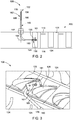
- FIG. 1 is a cross-sectional schematic view of an exemplary rotary machine.
- the rotary machine includes a turbine assembly 100.
- the rotary machine includes any assembly.
- the rotary machine includes, without limitation, any of the following: a compressor, a blower, a pump, a turbine, a motor, and a generator.
- turbine assembly 100 includes an inlet 102, a compressor 104, a combustor 106, a turbine 108, an outer case 109, and an exhaust 110. Fluid flows from inlet 102, through compressor 104, through combustor 106, through turbine 108 and is discharged through exhaust 110.
- compressor 104 and turbine 108 include airfoils configured to direct fluid through turbine assembly 100.
- compressor 104 and turbine 108 include blades 122, 125 and guide vanes 123, 124. Together, blades 122, 125, guide vanes 123, 124, and shrouds 113 (shown in FIG. 2 ) define a primary flowpath 152 of turbine assembly 100. This flowpath, combined with a flowpath through combustor 106, defines a primary cavity within turbine assembly 100.
- turbine assembly 100 is configured in any manner that enables turbine assembly 100 to operate as described herein.
- Blades 122, 125 are operably coupled with rotating shafts 114, 115 such that blades 122, 125 rotate when rotating shafts 114, 115 rotate. Accordingly, blades 122, 125 and rotating shafts 114, 115 form a rotor of turbine assembly 100.
- Guide vanes 123, 124 and shrouds 113 are stationary components and are coupled to an interior surface 121 of outer case 109. Blades 122, 125 and guide vanes 123, 124 are generally positioned alternatingly along the rotor axis within turbine assembly 100.
- compressor 104 and/or turbine 108 includes any airfoils that enable turbine assembly 100 to operate as described herein.
- FIG. 2 is a schematic view of an insertion apparatus 128 and service apparatus 101 positioned in the primary cavity of turbine assembly 100.
- FIG. 3 is a schematic view of service apparatus 101 positioned between adjacent blades 125 of turbine assembly 100.
- service apparatus 101 is configured to move through the primary flowpath of turbine assembly 100. Accordingly, service apparatus 101 facilitates maintenance of turbine assembly 100. For example, service apparatus 101 facilitates inspection and repair of turbine assembly 100 at locations within the primary flowpath that are difficult to access from an exterior of turbine assembly 100 by conventional means, such as using a borescope tool.
- Service apparatus 101 is positioned within the primary flowpath using insertion apparatus 128.
- insertion apparatus 128 is used to position service apparatus 101 adjacent rotating components of turbine assembly 100, such as blades 122, 125, and the rotating components are subsequently used to position service apparatus 101 relative to stationary components of turbine assembly 100.
- service apparatus 101 enters turbine assembly 100 through any suitable access port or opening of turbine assembly 100.
- service apparatus 101 enters and/or exits turbine assembly 100 through any of inlet 102, exhaust 110, and/or an access port, such as an igniter, borescope, or fuel nozzle port.
- service apparatus 101 is sized and shaped to fit within turbine assembly 100 and to travel through turbine assembly 100, such as through the primary cavity of turbine assembly 100.
- service apparatus 101 has a height, length, and width that are less than a clearance required to fit within the primary flowpath. The height, length, and width define a volume of service apparatus 101.
- service apparatus 101 is any size and shape that enables service apparatus 101 to operate as described herein.
- service apparatus 101 could be used to inspect and/or repair any interior components of turbine assembly 100.
- service apparatus 101 is positioned adjacent a portion of interior surface 121 of turbine assembly 100.
- Interior surface 121 is any surface within the primary flowpath of turbine assembly 100.
- interior surface 121 includes, without limitation, surfaces of blades 122, 125, guide vanes 123, 124, and shrouds 113.
- service apparatus 101 detects a characteristic of interior surface 121.
- service apparatus 101 is used to generate an image of interior surface 121 and the image is examined to determine the condition of turbine assembly 100 and assess whether repairs are necessary.
- service apparatus 101 is used to repair interior surface 121. For example, in some embodiments, service apparatus 101 removes and/or replaces a damaged portion of interior surface 121. After inspection and/or repair of interior surface 121, service apparatus 101 exits turbine assembly 100 through any suitable access port or opening of turbine assembly 100, such as via the route of entry.
- Insertion apparatus 128 includes an insertion end 130 and a steering end 132 opposite insertion end 130. Insertion end 130 is positionable within the primary flowpath of turbine assembly 100, such as adjacent blades 122, 125.
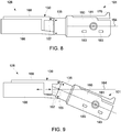
- service apparatus 101 is coupled to insertion end 130 of insertion apparatus 128 and is positionable in a plurality of orientations using a steering interface on steering end 132 of insertion apparatus 128. For example, in some embodiments, service apparatus 101 is pivoted between a first orientation (shown in FIG. 8 ) in which service apparatus 101 is aligned with a translation direction 164 and a second orientation (shown in FIG.
- service apparatus 101 extends at an angle relative to translation direction 164 so as to facilitate anchoring to at least one blade 122, 125.
- the ability to position service apparatus 101 in a plurality of orientations facilitates insertion of service apparatus into the target location within the primary flowpath and allows service apparatus 101 to anchor onto the rotor and perform service operations at otherwise difficult to access locations.
- service apparatus 101 is positionable in any orientation that enables service apparatus 101 to operate as described herein.
- a steering interface 138 is located at steering end 132 of insertion apparatus 128 and is configured to steer service apparatus 101 via insertion end 130.
- steering interface 138 includes one or more actuator members (such as elastic sheets driving kinematic linkages). For example, a user may hold and manipulate steering end 132.
- steering is at least partially automated.
- insertion apparatus 128 includes any steering interface 138 that enables insertion apparatus 128 to operate as described herein.
- a guide apparatus 140 extends through a port of turbine assembly 100 and defines a path for insertion apparatus 128.
- guide apparatus 140 includes a curved guide tube that is sized to receive insertion apparatus 128 within its interior space.
- Guide apparatus 140 may be fixed to turbine assembly 100 by a flange 142 coupled to a port of turbine assembly 100.
- flange 142 extends around guide apparatus 140 and is sized to fit onto a borescope or an igniter port of turbine assembly 100.
- guide apparatus 140 is coupled to turbine assembly 100 in any manner that enables guide apparatus 140 to operate as described herein.
- guide apparatus 140 is configured to direct insertion apparatus 128 within the primary cavity of turbine assembly 100.
- guide apparatus 140 is curved and defines a curved path for insertion apparatus 128.
- guide apparatus 140 is sized such that an insertion end 160 of guide apparatus 140 is positioned proximate a target area within turbine assembly 100.
- guide apparatus 140 positions insertion end 130 of insertion apparatus 128 between adjacent vanes 123, 124 and, using steering interface 138, advances insertion end 130 proximate a rotating component of turbine assembly 100, such as proximate blades 122, 125, thus facilitating anchoring service apparatus 101 between adjacent blades 122, 125.
- guide apparatus 140 is any size and shape that enables guide apparatus 140 to operate as described herein.
- insertion apparatus 128 allows precise positioning of service apparatus 101 within the primary flowpath of turbine assembly 100.
- insertion apparatus 128 is used to position service apparatus 101 proximate blades 122, 125 of turbine assembly 100.
- service apparatus 101 is anchored to a portion of turbine assembly 100.
- a rotating component of turbine assembly 100 is used to position service apparatus 101 proximate a stationary component of turbine assembly 100 that is difficult to access by conventional means. Accordingly, service apparatus 101 is positioned to perform service operations at difficult-to-access locations within turbine assembly 100.
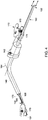
- FIG. 4 is a perspective view of insertion apparatus 128 and service apparatus 101.
- FIG. 5 is a side view of service apparatus 101.
- insertion apparatus 128 includes a body 162 extending from steering end 132 to insertion end 130
- Body 162 includes a first elastic sheet 166 and a second elastic sheet 168.
- insertion end 130 is steerable by moving, using steering interface 138 (shown in FIG. 2 ), first elastic sheet 166 and second elastic sheet 168 in opposing directions.
- first elastic sheet 166 and second elastic sheet 168 are flexible and bend elastically in a plane extending along the insertion path.
- first elastic sheet 166 and second elastic sheet 168 are relatively rigid in the plane of the sheets to allow transmission of the steering forces along the axis of the body 162 .
- first elastic sheet 166 and second elastic sheet 168 include elastically deformable sheets, such as fiberglass, spring steel, or any material that allows the first elastic sheet 166 and second elastic sheet 168 to elastically bend through the guide apparatus 140 in the translation direction while providing sufficient stiffness to allow forward forces on the steering interface 138 (shown in FIG. 2 ) to advance insertion end 130, and hence service apparatus 101, along the translation direction.
- insertion apparatus 128 includes any body 162 that enables insertion apparatus 128 to operate as described herein.
- body 162 includes a torsionally stiff tube or semi-rigid member that is compliant in bending and extends from insertion end 130 to steering end 132.
- insertion apparatus 128 includes a latching mechanism 135 that releasably couples service apparatus 101 to insertion end 130.
- service apparatus 101 and/or insertion apparatus 128 include magnets, hooks, latches, adhesives, and any other engagement mechanism that enables insertion apparatus 128 to operate as described herein.
- insertion apparatus 128 includes an actuator that is actuated from steering end 132 and causes latching mechanism 135 to disengage from service apparatus 101.
- insertion apparatus 128 includes a plurality of linkages 167 that facilitate pivoting of service apparatus 101 relative to blades 125 (shown in FIG. 3 ).
- Linkages 167 may be located on insertion end 130 of body 162 (shown in FIG. 4 ) and/or on latching mechanism 135.
- service apparatus 101 is coupled to insertion apparatus 128 in any manner that enables service apparatus 101 and insertion apparatus 128 to operate as described herein.
- a component such as a harness or tether 170, extends from service apparatus 101 to the exterior of turbine assembly 100.
- tether 170 provides power to service apparatus 101, allows service apparatus 101 to send and/or receive signals, and/or transmits mechanical force, fluids, or thermal energy to service apparatus 101.
- Insertion apparatus 128 includes a tensioning mechanism 172 configured to control the tension of tether 170.
- tensioning mechanism 172 prevents slack in tether 170 which could cause service apparatus 101 to be moved out of a desired position and/or hinder removal of service apparatus 101 from the primary flowpath.
- tensioning mechanism 172 includes a constant-force tensioning spring system with a reel 174.
- Tether 170 is wound around reel 174 of tensioning mechanism 172.
- Reel 174 maintains tension on tether 170.
- tensioning mechanism 172 maintains a desired tension in tether 170.
- service apparatus 101 includes any tether 170 and/or tensioning mechanism 172 that enables service apparatus 101 to operate as described herein.
- tensioning mechanism 172 employs an active tensioner, such as a motorized tensioner with closed-loop feedback control to maintain tension within the desired range.
- tensioning mechanism 172 is not required.
- tension on tether 170 is maintained manually by the operator.
- service apparatus 101 is sized to fit adjacent a rotating component within the primary flowpath of turbine assembly 100.
- service apparatus 101 is positioned, using insertion apparatus 128, within the primary flowpath of turbine assembly 100 between adjacent blades 125.
- service apparatus 101 is configured to anchor, using an anchoring feature 178 (shown in FIG. 5 ), to turbine assembly 100 to facilitate positioning service apparatus 101 adjacent a portion of turbine assembly 100 using a rotating component of turbine assembly 100.
- Anchoring feature 178 can be an actuated feature, such as a spring-loaded arm that engages features in blades 125 and is actuated from steering end 132.
- anchoring feature 178 can be a geometrical feature, such as a notch, that allows interlocking with the rotor, such as with blade 125, while tension is applied to tether 170.
- the rotating component of turbine assembly 100 is then used to position service apparatus 101 relative to stationary components of turbine assembly 100.
- service apparatus 101 is positioned in any manner that enables service apparatus 101 to operate as described herein.
- service apparatus 101 includes at least one maintenance device 180 to allow service apparatus 101 to perform an inspection and/or repair operation within the primary flowpath of turbine assembly 100.
- maintenance device 180 includes a camera 181 and an illuminator 183 (shown in FIG. 3 ).
- Illuminator 183 may comprise a light-emitting diode (LED).
- service apparatus 101 includes any maintenance device that enables service apparatus 101 to operate as described herein.
- maintenance device 180 of service apparatus 101 includes, without limitation, any of the following: an applicator, a drill, a grinder, a heater, a welding electrode, a sprayer, an optical sensor (e.g., visible, infrared, and/or multi-spectral sensor), a mechanical sensor (e.g., stylus profilometer, coordinate measurement probe, load transducer, linear variable differential transformer), a thermal sensor (e.g., pyrometer, thermocouple, resistance temperature detector), a magnetic sensor, an acoustic sensor (e.g., piezoelectric, microphone, ultrasound), and an electromagnetic sensor (e.g., eddy current, potential drop, x-ray).
- an applicator e.g., visible, infrared, and/or multi-spectral sensor
- a mechanical sensor e.g., stylus profilometer, coordinate measurement probe, load transducer, linear variable differential transformer
- a thermal sensor e.g., pyrometer, thermocouple, resistance temperature detector
- FIG. 6 is a flow chart of an exemplary method 200 of operating service apparatus 101.
- method 200 includes positioning 202 service apparatus 101 within a primary flowpath of turbine assembly 100 using insertion apparatus 128.
- Service apparatus 101 is coupled to insertion end 130 of insertion apparatus 128.
- Service apparatus 101 is positioned 202 within the primary flowpath of turbine assembly 100 by inserting insertion apparatus 128 and service apparatus 101 through any suitable opening or port of turbine assembly 100.
- insertion apparatus 128 is inserted through an igniter port and positioned within a primary cavity of combustor 106.
- Guide apparatus 140 facilitates positioning insertion apparatus 128 and service apparatus 101 within the primary flowpath.
- service apparatus 101 is positioned 202 within the primary flowpath of turbine assembly 100 in any manner that enables service apparatus 101 to operate as described herein.
- method 200 includes directing 204 insertion end 130 of insertion apparatus 128 through turbine assembly 100 using steering interface 138, which is configured to move insertion end 130 relative to turbine assembly 100.
- insertion end 130 is directed by moving body 162 along translation direction 164.
- insertion end 130 is directed by moving first elastic sheet 166 and second elastic sheet 168 in the same direction along translation direction 164.
- translation direction 164 includes at least one bend such that insertion end 130 extends along an axis that is at an angle relative to an axis through steering end 132.
- an axis extends through insertion end 130 and an angle of about 90° relative to the axis through steering end 132.
- insertion apparatus 128 is moved in any manner that enables insertion apparatus 128 to operate as described herein.
- method 200 includes positioning 206, via insertion end 130 of insertion apparatus 128, service apparatus 101 adjacent a rotating component of turbine assembly 100.
- method 200 includes transitioning 208 service apparatus 101 from a first orientation (e.g., as shown in FIG. 8 ) to a second orientation (e.g., as shown in FIG. 9 ) using steering interface 138.
- service apparatus 101 is pivoted about an axis perpendicular to translation direction 164 between the first and second orientations by moving first elastic sheet 166 and second elastic sheet 168 relative to each other along translation direction 164.
- first orientation service apparatus 101 extends along translation direction 164 so as to facilitate directing service apparatus 101 through vanes 123, 124.
- second orientation service apparatus 101 extends at an angle relative to translation direction 164 so as to position service apparatus 101 adjacent blades 122, 125.
- method 200 includes positioning 212 service apparatus 101 adjacent a portion of turbine assembly 100 using the rotating component of turbine assembly 100.
- service apparatus 101 is anchored to a rotating component of turbine assembly 100 and positioned proximate a non-rotating portion of turbine assembly 100 using the rotating component of turbine assembly 100. That is, the rotating component is rotated to a desired location and service apparatus 101 performs a service operation at the desired location.
- tensioning mechanism 172 is used to control the tension in tether 170. After the service operation is complete, the rotating component is returned to the insertion location for retrieval of service apparatus 101.
- method 200 includes inserting guide apparatus 140 through a port of turbine assembly 100 to define a path for insertion apparatus 128.
- guide apparatus 140 is inserted through an ignitor port of turbine assembly 100 to define a path for insertion apparatus 128.
- Flange 142 fits onto the ignitor port and couples guide apparatus 140 to turbine assembly 100.
- insertion apparatus 128 is inserted into the primary flowpath of turbine assembly 100 in any manner that enables insertion apparatus 128 to operate as described herein.
- FIG. 7 is a schematic view of an alternative embodiment of an insertion apparatus 300 and a service apparatus 302 for use with turbine assembly 100 (shown in FIG. 1 ).
- Insertion apparatus 300 includes an insertion end 304, a steering end 306 opposite insertion end 304, a body 308, and a steering interface 310. Insertion apparatus 300 is positionable within a primary flow path using a guide apparatus 312. Body 308 extends from insertion end 304 to steering end 306. Body 308 has a generally cylindrical shape and is elastically deformable in bending so as to change direction through guide apparatus 312. Service apparatus 302 is coupled to insertion end 304 of insertion apparatus 300 so that rotation and translation of steering end 304 translate into rotation and translation on service apparatus 302.
- Service apparatus also includes at least one anchoring feature 314 that facilitates maintaining position of service apparatus 302 relative to blades 122, 125 during rotation of rotating shafts 115 and performance of maintenance operations.
- insertion apparatus 300 includes any body 308 and/or any guide tube that enables insertion apparatus 300 to operate as described herein.
- steering interface 310 is located at steering end 306 of insertion apparatus 300 and is configured to steer insertion end 304, and hence service apparatus 302, relative to turbine assembly 100 (shown in FIG. 1 ). Insertion end 304 and service apparatus 302 are steerable by moving, using steering interface 310, body 308.
- insertion apparatus 128 includes any steering interface 138 that enables insertion apparatus 128 to operate as described herein.
- the above described embodiments provide an insertion apparatus and service apparatus for use with rotary machines.
- the insertion apparatus is configured to position the service apparatus within a primary flowpath of the machine.
- the insertion apparatus extends through a port of a turbine assembly and positions the service apparatus adjacent a rotating component of the turbine assembly using a steering interface.
- the service apparatus is releasably or rigidly coupleable to an insertion end of the insertion apparatus such that the service apparatus is positionable relative to the insertion apparatus.
- the insertion apparatus facilitates the service apparatus fitting between blades of the rotating component and provides access to locations within the primary flowpath of the machine.
- An exemplary technical effect of the methods, systems, and apparatus described herein includes at least one of: (a) reducing the time to inspect and/or repair rotary machines; (b) increasing the accessibility of difficult-to-reach locations within a turbine assembly for inspection and/or in situ repair; (c) reducing the time that rotary machines are out of service for maintenance; (e) increasing the precision and/or reliability of inspection and repair of rotary machines; (f) reducing unplanned service outages for a rotary machine; and (g) enhancing data capture for use in quantifying and/or modeling the service condition of at least some components of the rotary machine.
- Exemplary embodiments of methods and systems for use in maintaining rotary machines are not limited to the specific embodiments described herein, but rather, components of systems and/or steps of the methods may be utilized independently and separately from other components and/or steps described herein.
- the methods and systems may also be used in combination with other systems requiring inspection and/or repair of components, and are not limited to practice with only the systems and methods as described herein.
- the exemplary embodiment can be implemented and utilized in connection with many other applications, equipment, and systems that may benefit from using a service apparatus for inspection and/or repair.
Landscapes
- Engineering & Computer Science (AREA)
- Mechanical Engineering (AREA)
- General Engineering & Computer Science (AREA)
- Physics & Mathematics (AREA)
- Robotics (AREA)
- General Physics & Mathematics (AREA)
- Optics & Photonics (AREA)
- Chemical & Material Sciences (AREA)
- Combustion & Propulsion (AREA)
- Structures Of Non-Positive Displacement Pumps (AREA)
Applications Claiming Priority (1)
| Application Number | Priority Date | Filing Date | Title |
|---|---|---|---|
| US16/212,102 US11103964B2 (en) | 2018-12-06 | 2018-12-06 | Service apparatus for use with rotary machines |
Publications (2)
| Publication Number | Publication Date |
|---|---|
| EP3663515A1 true EP3663515A1 (de) | 2020-06-10 |
| EP3663515B1 EP3663515B1 (de) | 2025-03-26 |
Family
ID=68808156
Family Applications (1)
| Application Number | Title | Priority Date | Filing Date |
|---|---|---|---|
| EP19214096.0A Active EP3663515B1 (de) | 2018-12-06 | 2019-12-06 | Wartungsvorrichtung zur verwendung in turbinenanordnungen |
Country Status (3)
| Country | Link |
|---|---|
| US (1) | US11103964B2 (de) |
| EP (1) | EP3663515B1 (de) |
| CN (1) | CN111287807B (de) |
Cited By (2)
| Publication number | Priority date | Publication date | Assignee | Title |
|---|---|---|---|---|
| CN113803123A (zh) * | 2020-06-15 | 2021-12-17 | 通用电气公司 | 检查和维修工具 |
| US12447625B2 (en) | 2022-06-03 | 2025-10-21 | Oliver Crispin Robotics Limited | Systems and methods for aligning and localizing a tool |
Families Citing this family (7)
| Publication number | Priority date | Publication date | Assignee | Title |
|---|---|---|---|---|
| DE102018209609A1 (de) * | 2018-06-14 | 2019-12-19 | MTU Aero Engines AG | Inspektionsverfahren und System |
| US11608756B2 (en) | 2018-07-17 | 2023-03-21 | General Electric Company | Service apparatus for use with rotary machines |
| US11691844B2 (en) | 2021-01-14 | 2023-07-04 | General Electric Company | Cable tensioning systems |
| US11913345B2 (en) | 2021-07-26 | 2024-02-27 | General Electric Company | System and method of using a tool assembly |
| US11885228B2 (en) * | 2022-02-09 | 2024-01-30 | General Electric Company | System and method for inspecting fan blade tip clearance relative to an abradable fan case |
| US12195202B1 (en) * | 2024-01-26 | 2025-01-14 | General Electric Company | System and method for servicing aircraft engines |
| US12186848B1 (en) | 2024-01-26 | 2025-01-07 | General Electric Company | Method and apparatus for servicing engines |
Citations (5)
| Publication number | Priority date | Publication date | Assignee | Title |
|---|---|---|---|---|
| US4298312A (en) * | 1979-07-24 | 1981-11-03 | Purex Corporation | Damaged vane locating method and apparatus |
| EP2267508A2 (de) * | 2000-08-18 | 2010-12-29 | Oliver Crispin Robotics Limited | Verbesserungen bezüglich der Roboterpositionierung eines Werkzeuges oder eines Sensors |
| US20130232792A1 (en) * | 2012-03-12 | 2013-09-12 | General Electric Company | Apparatus and method for servicing turbomachinery components in-situ |
| US20180100396A1 (en) * | 2016-10-11 | 2018-04-12 | General Electric Company | System and method for maintenance of a turbine assembly |
| CA2957264A1 (en) * | 2017-02-07 | 2018-08-07 | General Electric Company | In situ gas turbine prevention of crack growth progression |
Family Cites Families (32)
| Publication number | Priority date | Publication date | Assignee | Title |
|---|---|---|---|---|
| US4659195A (en) * | 1986-01-31 | 1987-04-21 | American Hospital Supply Corporation | Engine inspection system |
| US4735501A (en) * | 1986-04-21 | 1988-04-05 | Identechs Corporation | Method and apparatus for fluid propelled borescopes |
| US4794912A (en) * | 1987-08-17 | 1989-01-03 | Welch Allyn, Inc. | Borescope or endoscope with fluid dynamic muscle |
| US4989581A (en) * | 1990-06-01 | 1991-02-05 | Welch Allyn, Inc. | Torsional strain relief for borescope |
| US5066122A (en) * | 1990-11-05 | 1991-11-19 | Welch Allyn, Inc. | Hooking cap for borescope |
| US6886422B2 (en) | 2002-10-09 | 2005-05-03 | General Electric Co. | Methods and apparatus for inspecting components |
| US7121098B2 (en) * | 2003-04-30 | 2006-10-17 | Siemens Power Generation, Inc. | High-temperature inspection device and cooling apparatus therefor |
| US7717666B2 (en) * | 2005-10-21 | 2010-05-18 | General Electric Company | Methods and apparatus for rotary machinery inspection |
| GB0808432D0 (en) | 2008-05-12 | 2008-06-18 | Rolls Royce Plc | An inspection arrangement |
| US20120312103A1 (en) * | 2009-11-10 | 2012-12-13 | Kerstin Hannott | Inspection device and method for positioning an inspection device |
| US8602722B2 (en) | 2010-02-26 | 2013-12-10 | General Electric Company | System and method for inspection of stator vanes |
| US8713775B2 (en) * | 2011-06-16 | 2014-05-06 | General Electric Company | Apparatus and method for servicing dynamoelectric machine components in-situ |
| US8365584B1 (en) * | 2011-07-13 | 2013-02-05 | General Electric Company | Apparatus for inspecting turbomachine components in-situ |
| US8713999B2 (en) * | 2012-01-31 | 2014-05-06 | Siemens Energy, Inc. | System and method for automated optical inspection of industrial gas turbines and other power generation machinery with multi-axis inspection scope |
| GB201204913D0 (en) | 2012-03-21 | 2012-05-02 | Rolls Royce Plc | An inspection device for an internal combustion engine |
| JP2015526642A (ja) * | 2012-08-23 | 2015-09-10 | シーメンス エナジー インコーポレイテッド | 回転ギアモード中のオフライン産業用ガスタービンおよび他の発電機械の光学検査システムおよび方法 |
| GB2507980B (en) | 2012-11-15 | 2015-06-10 | Rolls Royce Plc | Inspection arrangement |
| KR20140068446A (ko) | 2012-11-28 | 2014-06-09 | 배수규 | 항공기 엔진 검사장치 |
| GB2512059B (en) * | 2013-03-18 | 2016-08-31 | Rolls Royce Plc | An independently moveable machine tool |
| US9513117B2 (en) | 2013-10-02 | 2016-12-06 | Siemens Energy, Inc. | Situ blade mounted tip gap measurement for turbines |
| EP3281054A1 (de) * | 2015-04-10 | 2018-02-14 | General Electric Company | Systeme und verfahren zur befestigung einer flexiblen boreskopsonde oder eines führungsrohrs an einer komponente eines gasturbinenmotors |
| US10142565B2 (en) * | 2015-04-13 | 2018-11-27 | Siemens Energy, Inc. | Flash thermography borescope |
| GB2544058A (en) | 2015-11-03 | 2017-05-10 | Rolls Royce Plc | Inspection apparatus and methods of inspecting gas turbine engines |
| US9733195B2 (en) * | 2015-12-18 | 2017-08-15 | General Electric Company | System and method for inspecting turbine blades |
| US10473528B2 (en) * | 2016-02-13 | 2019-11-12 | General Electric Company | Optical apparatus and sight tube for inspecting turbine engine components |
| US10125611B2 (en) * | 2016-02-17 | 2018-11-13 | General Electric Company | System and method for in situ repair of turbine blades of gas turbine engines |
| US10920590B2 (en) * | 2016-06-30 | 2021-02-16 | General Electric Company | Turbine assembly maintenance methods |
| US20180117731A1 (en) * | 2016-09-09 | 2018-05-03 | Advanced Turbine Support, LLC | Industrial High Speed Micro Drill |
| CN110049829A (zh) * | 2016-10-14 | 2019-07-23 | 通用电气公司 | 燃气涡轮发动机清洗系统 |
| US9879981B1 (en) * | 2016-12-02 | 2018-01-30 | General Electric Company | Systems and methods for evaluating component strain |
| GB201713277D0 (en) * | 2017-08-18 | 2017-10-04 | Rolls Royce Plc | Hyper-redundant manipulators |
| US10712290B2 (en) * | 2018-04-30 | 2020-07-14 | General Electric Company | Techniques for control of non-destructive testing devices via a probe driver |
-
2018
- 2018-12-06 US US16/212,102 patent/US11103964B2/en active Active
-
2019
- 2019-12-06 CN CN201911241777.6A patent/CN111287807B/zh active Active
- 2019-12-06 EP EP19214096.0A patent/EP3663515B1/de active Active
Patent Citations (5)
| Publication number | Priority date | Publication date | Assignee | Title |
|---|---|---|---|---|
| US4298312A (en) * | 1979-07-24 | 1981-11-03 | Purex Corporation | Damaged vane locating method and apparatus |
| EP2267508A2 (de) * | 2000-08-18 | 2010-12-29 | Oliver Crispin Robotics Limited | Verbesserungen bezüglich der Roboterpositionierung eines Werkzeuges oder eines Sensors |
| US20130232792A1 (en) * | 2012-03-12 | 2013-09-12 | General Electric Company | Apparatus and method for servicing turbomachinery components in-situ |
| US20180100396A1 (en) * | 2016-10-11 | 2018-04-12 | General Electric Company | System and method for maintenance of a turbine assembly |
| CA2957264A1 (en) * | 2017-02-07 | 2018-08-07 | General Electric Company | In situ gas turbine prevention of crack growth progression |
Cited By (3)
| Publication number | Priority date | Publication date | Assignee | Title |
|---|---|---|---|---|
| CN113803123A (zh) * | 2020-06-15 | 2021-12-17 | 通用电气公司 | 检查和维修工具 |
| US12420953B2 (en) | 2020-06-15 | 2025-09-23 | General Electric Company | Inspection and repair tool |
| US12447625B2 (en) | 2022-06-03 | 2025-10-21 | Oliver Crispin Robotics Limited | Systems and methods for aligning and localizing a tool |
Also Published As
| Publication number | Publication date |
|---|---|
| CN111287807A (zh) | 2020-06-16 |
| EP3663515B1 (de) | 2025-03-26 |
| US20200180084A1 (en) | 2020-06-11 |
| US11103964B2 (en) | 2021-08-31 |
| CN111287807B (zh) | 2023-03-28 |
Similar Documents
| Publication | Publication Date | Title |
|---|---|---|
| EP3663515B1 (de) | Wartungsvorrichtung zur verwendung in turbinenanordnungen | |
| EP3510251B1 (de) | Wartungsvorrichtung und verfahren zur wartung einer turbinenanordnung | |
| CA3094679C (en) | Insertion apparatus for use with rotary machines | |
| US12420953B2 (en) | Inspection and repair tool | |
| EP3631170B1 (de) | Wartungsvorrichtung zur verwendung in drehmaschinen | |
| US11260477B2 (en) | Repair tool for turbomachinery and related method | |
| EP4234894B1 (de) | Wartungsverfahren für turbinenanordnung | |
| US11248465B2 (en) | Reconfigurable maintenance apparatus | |
| US10494926B2 (en) | System and method for maintaining machines | |
| US11608756B2 (en) | Service apparatus for use with rotary machines | |
| EP3658880B1 (de) | Systeme und verfahren zur inspektion von schaufeln oder flügeln bei turbomaschinen | |
| EP3816396A2 (de) | Einführungsvorrichtung zur verwendung mit drehmaschinen |
Legal Events
| Date | Code | Title | Description |
|---|---|---|---|
| PUAI | Public reference made under article 153(3) epc to a published international application that has entered the european phase |
Free format text: ORIGINAL CODE: 0009012 |
|
| STAA | Information on the status of an ep patent application or granted ep patent |
Free format text: STATUS: THE APPLICATION HAS BEEN PUBLISHED |
|
| AK | Designated contracting states |
Kind code of ref document: A1 Designated state(s): AL AT BE BG CH CY CZ DE DK EE ES FI FR GB GR HR HU IE IS IT LI LT LU LV MC MK MT NL NO PL PT RO RS SE SI SK SM TR |
|
| AX | Request for extension of the european patent |
Extension state: BA ME |
|
| STAA | Information on the status of an ep patent application or granted ep patent |
Free format text: STATUS: REQUEST FOR EXAMINATION WAS MADE |
|
| 17P | Request for examination filed |
Effective date: 20201207 |
|
| RBV | Designated contracting states (corrected) |
Designated state(s): AL AT BE BG CH CY CZ DE DK EE ES FI FR GB GR HR HU IE IS IT LI LT LU LV MC MK MT NL NO PL PT RO RS SE SI SK SM TR |
|
| STAA | Information on the status of an ep patent application or granted ep patent |
Free format text: STATUS: EXAMINATION IS IN PROGRESS |
|
| 17Q | First examination report despatched |
Effective date: 20210517 |
|
| GRAP | Despatch of communication of intention to grant a patent |
Free format text: ORIGINAL CODE: EPIDOSNIGR1 |
|
| STAA | Information on the status of an ep patent application or granted ep patent |
Free format text: STATUS: GRANT OF PATENT IS INTENDED |
|
| INTG | Intention to grant announced |
Effective date: 20241104 |
|
| GRAS | Grant fee paid |
Free format text: ORIGINAL CODE: EPIDOSNIGR3 |
|
| GRAA | (expected) grant |
Free format text: ORIGINAL CODE: 0009210 |
|
| STAA | Information on the status of an ep patent application or granted ep patent |
Free format text: STATUS: THE PATENT HAS BEEN GRANTED |
|
| AK | Designated contracting states |
Kind code of ref document: B1 Designated state(s): AL AT BE BG CH CY CZ DE DK EE ES FI FR GB GR HR HU IE IS IT LI LT LU LV MC MK MT NL NO PL PT RO RS SE SI SK SM TR |
|
| REG | Reference to a national code |
Ref country code: GB Ref legal event code: FG4D |
|
| REG | Reference to a national code |
Ref country code: CH Ref legal event code: EP |
|
| REG | Reference to a national code |
Ref country code: DE Ref legal event code: R096 Ref document number: 602019067713 Country of ref document: DE |
|
| REG | Reference to a national code |
Ref country code: IE Ref legal event code: FG4D |
|
| P01 | Opt-out of the competence of the unified patent court (upc) registered |
Free format text: CASE NUMBER: APP_14194/2025 Effective date: 20250324 |
|
| PG25 | Lapsed in a contracting state [announced via postgrant information from national office to epo] |
Ref country code: RS Free format text: LAPSE BECAUSE OF FAILURE TO SUBMIT A TRANSLATION OF THE DESCRIPTION OR TO PAY THE FEE WITHIN THE PRESCRIBED TIME-LIMIT Effective date: 20250626 |
|
| PG25 | Lapsed in a contracting state [announced via postgrant information from national office to epo] |
Ref country code: FI Free format text: LAPSE BECAUSE OF FAILURE TO SUBMIT A TRANSLATION OF THE DESCRIPTION OR TO PAY THE FEE WITHIN THE PRESCRIBED TIME-LIMIT Effective date: 20250326 |
|
| REG | Reference to a national code |
Ref country code: LT Ref legal event code: MG9D |
|
| PG25 | Lapsed in a contracting state [announced via postgrant information from national office to epo] |
Ref country code: NO Free format text: LAPSE BECAUSE OF FAILURE TO SUBMIT A TRANSLATION OF THE DESCRIPTION OR TO PAY THE FEE WITHIN THE PRESCRIBED TIME-LIMIT Effective date: 20250626 |
|
| PG25 | Lapsed in a contracting state [announced via postgrant information from national office to epo] |
Ref country code: HR Free format text: LAPSE BECAUSE OF FAILURE TO SUBMIT A TRANSLATION OF THE DESCRIPTION OR TO PAY THE FEE WITHIN THE PRESCRIBED TIME-LIMIT Effective date: 20250326 |
|
| PG25 | Lapsed in a contracting state [announced via postgrant information from national office to epo] |
Ref country code: LV Free format text: LAPSE BECAUSE OF FAILURE TO SUBMIT A TRANSLATION OF THE DESCRIPTION OR TO PAY THE FEE WITHIN THE PRESCRIBED TIME-LIMIT Effective date: 20250326 |
|
| PG25 | Lapsed in a contracting state [announced via postgrant information from national office to epo] |
Ref country code: GR Free format text: LAPSE BECAUSE OF FAILURE TO SUBMIT A TRANSLATION OF THE DESCRIPTION OR TO PAY THE FEE WITHIN THE PRESCRIBED TIME-LIMIT Effective date: 20250627 Ref country code: BG Free format text: LAPSE BECAUSE OF FAILURE TO SUBMIT A TRANSLATION OF THE DESCRIPTION OR TO PAY THE FEE WITHIN THE PRESCRIBED TIME-LIMIT Effective date: 20250326 |
|
| REG | Reference to a national code |
Ref country code: NL Ref legal event code: MP Effective date: 20250326 |
|
| PG25 | Lapsed in a contracting state [announced via postgrant information from national office to epo] |
Ref country code: NL Free format text: LAPSE BECAUSE OF FAILURE TO SUBMIT A TRANSLATION OF THE DESCRIPTION OR TO PAY THE FEE WITHIN THE PRESCRIBED TIME-LIMIT Effective date: 20250326 |
|
| PG25 | Lapsed in a contracting state [announced via postgrant information from national office to epo] |
Ref country code: SE Free format text: LAPSE BECAUSE OF FAILURE TO SUBMIT A TRANSLATION OF THE DESCRIPTION OR TO PAY THE FEE WITHIN THE PRESCRIBED TIME-LIMIT Effective date: 20250326 |
|
| REG | Reference to a national code |
Ref country code: AT Ref legal event code: MK05 Ref document number: 1779148 Country of ref document: AT Kind code of ref document: T Effective date: 20250326 |
|
| PG25 | Lapsed in a contracting state [announced via postgrant information from national office to epo] |
Ref country code: SM Free format text: LAPSE BECAUSE OF FAILURE TO SUBMIT A TRANSLATION OF THE DESCRIPTION OR TO PAY THE FEE WITHIN THE PRESCRIBED TIME-LIMIT Effective date: 20250326 |
|
| PG25 | Lapsed in a contracting state [announced via postgrant information from national office to epo] |
Ref country code: PT Free format text: LAPSE BECAUSE OF FAILURE TO SUBMIT A TRANSLATION OF THE DESCRIPTION OR TO PAY THE FEE WITHIN THE PRESCRIBED TIME-LIMIT Effective date: 20250728 Ref country code: ES Free format text: LAPSE BECAUSE OF FAILURE TO SUBMIT A TRANSLATION OF THE DESCRIPTION OR TO PAY THE FEE WITHIN THE PRESCRIBED TIME-LIMIT Effective date: 20250326 |
|
| PG25 | Lapsed in a contracting state [announced via postgrant information from national office to epo] |
Ref country code: PL Free format text: LAPSE BECAUSE OF FAILURE TO SUBMIT A TRANSLATION OF THE DESCRIPTION OR TO PAY THE FEE WITHIN THE PRESCRIBED TIME-LIMIT Effective date: 20250326 Ref country code: IT Free format text: LAPSE BECAUSE OF FAILURE TO SUBMIT A TRANSLATION OF THE DESCRIPTION OR TO PAY THE FEE WITHIN THE PRESCRIBED TIME-LIMIT Effective date: 20250326 |
|
| PG25 | Lapsed in a contracting state [announced via postgrant information from national office to epo] |
Ref country code: AT Free format text: LAPSE BECAUSE OF FAILURE TO SUBMIT A TRANSLATION OF THE DESCRIPTION OR TO PAY THE FEE WITHIN THE PRESCRIBED TIME-LIMIT Effective date: 20250326 |
|
| PG25 | Lapsed in a contracting state [announced via postgrant information from national office to epo] |
Ref country code: EE Free format text: LAPSE BECAUSE OF FAILURE TO SUBMIT A TRANSLATION OF THE DESCRIPTION OR TO PAY THE FEE WITHIN THE PRESCRIBED TIME-LIMIT Effective date: 20250326 |
|
| PG25 | Lapsed in a contracting state [announced via postgrant information from national office to epo] |
Ref country code: RO Free format text: LAPSE BECAUSE OF FAILURE TO SUBMIT A TRANSLATION OF THE DESCRIPTION OR TO PAY THE FEE WITHIN THE PRESCRIBED TIME-LIMIT Effective date: 20250326 |
|
| PG25 | Lapsed in a contracting state [announced via postgrant information from national office to epo] |
Ref country code: SK Free format text: LAPSE BECAUSE OF FAILURE TO SUBMIT A TRANSLATION OF THE DESCRIPTION OR TO PAY THE FEE WITHIN THE PRESCRIBED TIME-LIMIT Effective date: 20250326 |
|
| PG25 | Lapsed in a contracting state [announced via postgrant information from national office to epo] |
Ref country code: IS Free format text: LAPSE BECAUSE OF FAILURE TO SUBMIT A TRANSLATION OF THE DESCRIPTION OR TO PAY THE FEE WITHIN THE PRESCRIBED TIME-LIMIT Effective date: 20250726 |
|
| PGFP | Annual fee paid to national office [announced via postgrant information from national office to epo] |
Ref country code: DE Payment date: 20251126 Year of fee payment: 7 |
|
| PGFP | Annual fee paid to national office [announced via postgrant information from national office to epo] |
Ref country code: GB Payment date: 20251120 Year of fee payment: 7 |
|
| PG25 | Lapsed in a contracting state [announced via postgrant information from national office to epo] |
Ref country code: DK Free format text: LAPSE BECAUSE OF FAILURE TO SUBMIT A TRANSLATION OF THE DESCRIPTION OR TO PAY THE FEE WITHIN THE PRESCRIBED TIME-LIMIT Effective date: 20250326 |
|
| PGFP | Annual fee paid to national office [announced via postgrant information from national office to epo] |
Ref country code: FR Payment date: 20251120 Year of fee payment: 7 |
|
| PG25 | Lapsed in a contracting state [announced via postgrant information from national office to epo] |
Ref country code: CZ Free format text: LAPSE BECAUSE OF FAILURE TO SUBMIT A TRANSLATION OF THE DESCRIPTION OR TO PAY THE FEE WITHIN THE PRESCRIBED TIME-LIMIT Effective date: 20250326 |
|
| PLBE | No opposition filed within time limit |
Free format text: ORIGINAL CODE: 0009261 |
|
| STAA | Information on the status of an ep patent application or granted ep patent |
Free format text: STATUS: NO OPPOSITION FILED WITHIN TIME LIMIT |
|
| REG | Reference to a national code |
Ref country code: CH Ref legal event code: L10 Free format text: ST27 STATUS EVENT CODE: U-0-0-L10-L00 (AS PROVIDED BY THE NATIONAL OFFICE) Effective date: 20260211 |