EP3663492A1 - Vehicle door latch device - Google Patents
Vehicle door latch device Download PDFInfo
- Publication number
- EP3663492A1 EP3663492A1 EP17918303.3A EP17918303A EP3663492A1 EP 3663492 A1 EP3663492 A1 EP 3663492A1 EP 17918303 A EP17918303 A EP 17918303A EP 3663492 A1 EP3663492 A1 EP 3663492A1
- Authority
- EP
- European Patent Office
- Prior art keywords
- cable
- door latch
- door
- inner cable
- handle
- Prior art date
- Legal status (The legal status is an assumption and is not a legal conclusion. Google has not performed a legal analysis and makes no representation as to the accuracy of the status listed.)
- Granted
Links
Images




Classifications
-
- F—MECHANICAL ENGINEERING; LIGHTING; HEATING; WEAPONS; BLASTING
- F16—ENGINEERING ELEMENTS AND UNITS; GENERAL MEASURES FOR PRODUCING AND MAINTAINING EFFECTIVE FUNCTIONING OF MACHINES OR INSTALLATIONS; THERMAL INSULATION IN GENERAL
- F16C—SHAFTS; FLEXIBLE SHAFTS; ELEMENTS OR CRANKSHAFT MECHANISMS; ROTARY BODIES OTHER THAN GEARING ELEMENTS; BEARINGS
- F16C1/00—Flexible shafts; Mechanical means for transmitting movement in a flexible sheathing
- F16C1/10—Means for transmitting linear movement in a flexible sheathing, e.g. "Bowden-mechanisms"
- F16C1/102—Arrangements to mount end fittings of the sheathings to support walls or brackets
-
- E—FIXED CONSTRUCTIONS
- E05—LOCKS; KEYS; WINDOW OR DOOR FITTINGS; SAFES
- E05B—LOCKS; ACCESSORIES THEREFOR; HANDCUFFS
- E05B79/00—Mounting or connecting vehicle locks or parts thereof
- E05B79/10—Connections between movable lock parts
- E05B79/20—Connections between movable lock parts using flexible connections, e.g. Bowden cables
-
- B—PERFORMING OPERATIONS; TRANSPORTING
- B60—VEHICLES IN GENERAL
- B60J—WINDOWS, WINDSCREENS, NON-FIXED ROOFS, DOORS, OR SIMILAR DEVICES FOR VEHICLES; REMOVABLE EXTERNAL PROTECTIVE COVERINGS SPECIALLY ADAPTED FOR VEHICLES
- B60J5/00—Doors
- B60J5/04—Doors arranged at the vehicle sides
- B60J5/0468—Fixation or mounting means specific for door components
-
- E—FIXED CONSTRUCTIONS
- E05—LOCKS; KEYS; WINDOW OR DOOR FITTINGS; SAFES
- E05B—LOCKS; ACCESSORIES THEREFOR; HANDCUFFS
- E05B77/00—Vehicle locks characterised by special functions or purposes
- E05B77/34—Protection against weather or dirt, e.g. against water ingress
-
- F—MECHANICAL ENGINEERING; LIGHTING; HEATING; WEAPONS; BLASTING
- F16—ENGINEERING ELEMENTS AND UNITS; GENERAL MEASURES FOR PRODUCING AND MAINTAINING EFFECTIVE FUNCTIONING OF MACHINES OR INSTALLATIONS; THERMAL INSULATION IN GENERAL
- F16C—SHAFTS; FLEXIBLE SHAFTS; ELEMENTS OR CRANKSHAFT MECHANISMS; ROTARY BODIES OTHER THAN GEARING ELEMENTS; BEARINGS
- F16C1/00—Flexible shafts; Mechanical means for transmitting movement in a flexible sheathing
- F16C1/10—Means for transmitting linear movement in a flexible sheathing, e.g. "Bowden-mechanisms"
-
- F—MECHANICAL ENGINEERING; LIGHTING; HEATING; WEAPONS; BLASTING
- F16—ENGINEERING ELEMENTS AND UNITS; GENERAL MEASURES FOR PRODUCING AND MAINTAINING EFFECTIVE FUNCTIONING OF MACHINES OR INSTALLATIONS; THERMAL INSULATION IN GENERAL
- F16C—SHAFTS; FLEXIBLE SHAFTS; ELEMENTS OR CRANKSHAFT MECHANISMS; ROTARY BODIES OTHER THAN GEARING ELEMENTS; BEARINGS
- F16C1/00—Flexible shafts; Mechanical means for transmitting movement in a flexible sheathing
- F16C1/10—Means for transmitting linear movement in a flexible sheathing, e.g. "Bowden-mechanisms"
- F16C1/107—Sealing details
-
- F—MECHANICAL ENGINEERING; LIGHTING; HEATING; WEAPONS; BLASTING
- F16—ENGINEERING ELEMENTS AND UNITS; GENERAL MEASURES FOR PRODUCING AND MAINTAINING EFFECTIVE FUNCTIONING OF MACHINES OR INSTALLATIONS; THERMAL INSULATION IN GENERAL
- F16C—SHAFTS; FLEXIBLE SHAFTS; ELEMENTS OR CRANKSHAFT MECHANISMS; ROTARY BODIES OTHER THAN GEARING ELEMENTS; BEARINGS
- F16C1/00—Flexible shafts; Mechanical means for transmitting movement in a flexible sheathing
- F16C1/10—Means for transmitting linear movement in a flexible sheathing, e.g. "Bowden-mechanisms"
- F16C1/12—Arrangements for transmitting movement to or from the flexible member
- F16C1/14—Construction of the end-piece of the flexible member; Attachment thereof to the flexible member
-
- F—MECHANICAL ENGINEERING; LIGHTING; HEATING; WEAPONS; BLASTING
- F16—ENGINEERING ELEMENTS AND UNITS; GENERAL MEASURES FOR PRODUCING AND MAINTAINING EFFECTIVE FUNCTIONING OF MACHINES OR INSTALLATIONS; THERMAL INSULATION IN GENERAL
- F16C—SHAFTS; FLEXIBLE SHAFTS; ELEMENTS OR CRANKSHAFT MECHANISMS; ROTARY BODIES OTHER THAN GEARING ELEMENTS; BEARINGS
- F16C1/00—Flexible shafts; Mechanical means for transmitting movement in a flexible sheathing
- F16C1/10—Means for transmitting linear movement in a flexible sheathing, e.g. "Bowden-mechanisms"
- F16C1/12—Arrangements for transmitting movement to or from the flexible member
- F16C1/14—Construction of the end-piece of the flexible member; Attachment thereof to the flexible member
- F16C1/145—Attachment of the end-piece to the flexible member
-
- F—MECHANICAL ENGINEERING; LIGHTING; HEATING; WEAPONS; BLASTING
- F16—ENGINEERING ELEMENTS AND UNITS; GENERAL MEASURES FOR PRODUCING AND MAINTAINING EFFECTIVE FUNCTIONING OF MACHINES OR INSTALLATIONS; THERMAL INSULATION IN GENERAL
- F16C—SHAFTS; FLEXIBLE SHAFTS; ELEMENTS OR CRANKSHAFT MECHANISMS; ROTARY BODIES OTHER THAN GEARING ELEMENTS; BEARINGS
- F16C1/00—Flexible shafts; Mechanical means for transmitting movement in a flexible sheathing
- F16C1/10—Means for transmitting linear movement in a flexible sheathing, e.g. "Bowden-mechanisms"
- F16C1/12—Arrangements for transmitting movement to or from the flexible member
- F16C1/16—Arrangements for transmitting movement to or from the flexible member in which the end-piece is guided rectilinearly
-
- F—MECHANICAL ENGINEERING; LIGHTING; HEATING; WEAPONS; BLASTING
- F16—ENGINEERING ELEMENTS AND UNITS; GENERAL MEASURES FOR PRODUCING AND MAINTAINING EFFECTIVE FUNCTIONING OF MACHINES OR INSTALLATIONS; THERMAL INSULATION IN GENERAL
- F16C—SHAFTS; FLEXIBLE SHAFTS; ELEMENTS OR CRANKSHAFT MECHANISMS; ROTARY BODIES OTHER THAN GEARING ELEMENTS; BEARINGS
- F16C1/00—Flexible shafts; Mechanical means for transmitting movement in a flexible sheathing
- F16C1/10—Means for transmitting linear movement in a flexible sheathing, e.g. "Bowden-mechanisms"
- F16C1/20—Construction of flexible members moved to and fro in the sheathing
- F16C1/205—Details of the outer surface of the flexible member, e.g. coatings
-
- F—MECHANICAL ENGINEERING; LIGHTING; HEATING; WEAPONS; BLASTING
- F16—ENGINEERING ELEMENTS AND UNITS; GENERAL MEASURES FOR PRODUCING AND MAINTAINING EFFECTIVE FUNCTIONING OF MACHINES OR INSTALLATIONS; THERMAL INSULATION IN GENERAL
- F16C—SHAFTS; FLEXIBLE SHAFTS; ELEMENTS OR CRANKSHAFT MECHANISMS; ROTARY BODIES OTHER THAN GEARING ELEMENTS; BEARINGS
- F16C1/00—Flexible shafts; Mechanical means for transmitting movement in a flexible sheathing
- F16C1/24—Lubrication; Lubricating equipment
-
- E—FIXED CONSTRUCTIONS
- E05—LOCKS; KEYS; WINDOW OR DOOR FITTINGS; SAFES
- E05B—LOCKS; ACCESSORIES THEREFOR; HANDCUFFS
- E05B79/00—Mounting or connecting vehicle locks or parts thereof
- E05B79/02—Mounting of vehicle locks or parts thereof
- E05B79/06—Mounting of handles, e.g. to the wing or to the lock
-
- E—FIXED CONSTRUCTIONS
- E05—LOCKS; KEYS; WINDOW OR DOOR FITTINGS; SAFES
- E05B—LOCKS; ACCESSORIES THEREFOR; HANDCUFFS
- E05B85/00—Details of vehicle locks not provided for in groups E05B77/00 - E05B83/00
- E05B85/20—Bolts or detents
- E05B85/24—Bolts rotating about an axis
- E05B85/243—Bolts rotating about an axis with a bifurcated bolt
-
- E—FIXED CONSTRUCTIONS
- E05—LOCKS; KEYS; WINDOW OR DOOR FITTINGS; SAFES
- E05Y—INDEXING SCHEME ASSOCIATED WITH SUBCLASSES E05D AND E05F, RELATING TO CONSTRUCTION ELEMENTS, ELECTRIC CONTROL, POWER SUPPLY, POWER SIGNAL OR TRANSMISSION, USER INTERFACES, MOUNTING OR COUPLING, DETAILS, ACCESSORIES, AUXILIARY OPERATIONS NOT OTHERWISE PROVIDED FOR, APPLICATION THEREOF
- E05Y2201/00—Constructional elements; Accessories therefor
- E05Y2201/60—Suspension or transmission members; Accessories therefor
- E05Y2201/622—Suspension or transmission members elements
- E05Y2201/644—Flexible elongated pulling elements
- E05Y2201/654—Cables
-
- E—FIXED CONSTRUCTIONS
- E05—LOCKS; KEYS; WINDOW OR DOOR FITTINGS; SAFES
- E05Y—INDEXING SCHEME ASSOCIATED WITH SUBCLASSES E05D AND E05F, RELATING TO CONSTRUCTION ELEMENTS, ELECTRIC CONTROL, POWER SUPPLY, POWER SIGNAL OR TRANSMISSION, USER INTERFACES, MOUNTING OR COUPLING, DETAILS, ACCESSORIES, AUXILIARY OPERATIONS NOT OTHERWISE PROVIDED FOR, APPLICATION THEREOF
- E05Y2900/00—Application of doors, windows, wings or fittings thereof
- E05Y2900/50—Application of doors, windows, wings or fittings thereof for vehicles
- E05Y2900/53—Type of wing
- E05Y2900/531—Doors
Definitions
- the cover portion of the elasticity cap is formed in a bellows shape capable of expansion and contraction in the movement direction of the inner cable, and that the inner cable is bonded with adhesive to an outlet of the cover portion.
- Figure 7A is a longitudinal sectional view of a main section of outside handle 3 according to the second embodiment in a non-operated state.
- Figure 7B is a longitudinal sectional view of a main section of outside handle 3 according to the second embodiment in an operated state.
Landscapes
- Engineering & Computer Science (AREA)
- General Engineering & Computer Science (AREA)
- Mechanical Engineering (AREA)
- Health & Medical Sciences (AREA)
- Oral & Maxillofacial Surgery (AREA)
- Lock And Its Accessories (AREA)
- Flexible Shafts (AREA)
Abstract
Description
- This application is based upon and claims the benefit of priority from Japanese Patent Application No.
2017-140896, filed on July 20, 2017 - The present invention relates to a vehicle door latch device that includes a Bowden cable for transmitting operation of an outside handle to a door latch mechanism.
- A door latch mechanism is disposed in a door, and releases engagement with a striker on a vehicle body side based on door opening operation of an outside handle provided in the door outside a vehicle to enable the door to be opened. A Bowden cable is used as means for transmitting door opening operation of the outside handle to a door latch device.
- Patent Literature 1 describes a Bowden cable that includes an outer cable and an inner cable inserted into the outer cable. The inner cable is coupled at one end to an outside handle, and at the other end to a release lever of a door latch mechanism. Accordingly, when the outside handle is subjected to door opening operation, the inner cable is pulled up to operate the release lever.
- Patent Literature 1:
U.S. Patent No. 8414038 - The object of the present invention described above, and other objects, features and advantages of the present invention, will be made apparent by detailed descriptions below with reference to accompanying drawings each showing an example of the present application.
- Unfortunately, an outside handle disposed on a vehicle exterior side of a door is generally disposed above a door latch mechanism, so that one end of each of an inner cable and an outer cable coupled to the outside handle faces upward. This may cause rainwater entering the inside of the door along the outside handle to enter the inside of the outer cable. When rainwater enters the inside of the outer cable, freezing or rust may occur inside the outer cable to cause a malfunction.
- The present invention is made in light of the above-mentioned circumstances, and an object thereof is to provide a vehicle door latch device that prevents ingress of rainwater into an outer cable of a Bowden cable.
- To solve the technical problem described above, technical means according to the present invention includes: an operation handle supported by a handle base provided in a door; a door latch mechanism that maintains the door in a closed state; a Bowden cable having an outer cable that is fixed at one end to the handle base and at the other end to the door latch mechanism, and an inner cable that is inserted into the outer cable while being coupled at one end to the operation handle and at the other end to a release lever of the door latch mechanism; and an elastic cap having a cover portion in a cylindrical shape, extending in a movement direction of the inner cable to cover the inner cable extending from the one end of the outer cable.
- It is preferable that the cover portion of the elasticity cap is formed in a bellows shape capable of expansion and contraction in the movement direction of the inner cable, and that the inner cable is bonded with adhesive to an outlet of the cover portion.
- It is preferable that the elastic cap is filled with grease.
- It is preferable that the door latch mechanism includes a cable holding portion for fixing the other end of the outer cable, and that the cable holding portion fixes the other end of the outer cable while being engaged with the Bowden cable in its axial direction and around its axis.
- According to the present invention, providing the elastic cap covering the inner cable extending from one end upward of the outer cable enables stable operation to be acquired over a long period by preventing ingress of rainwater into the outer cable.
-
- [
Figure 1] Figure 1 is a side view of a door using a vehicle door latch device according to the present invention. - [
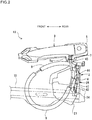
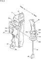
Figure 2] Figure 2 is a side view of an outside handle and a door latch mechanism. - [
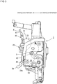
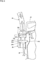
Figure 3] Figure 3 is a front view of a door latch mechanism. - [
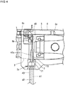
Figure 4] Figure 4 is an enlarged front view of the vicinity of an outside handle using a first embodiment. - [
Figure 5] Figure 5 an enlarged front view of the vicinity of an outside handle using a second embodiment. - [
Figure 6A] Figure 6A is a longitudinal sectional view of an outside handle according to the first embodiment in a non-operated state. - [
Figure 6B] Figure 6B is a longitudinal sectional view of an outside handle according to the first embodiment in an operated state. - [
Figure 7A] Figure 7A is a longitudinal sectional view of an outside handle according to the second embodiment in a non-operated state. - [
Figure 7B] Figure 7B is a longitudinal sectional view of an outside handle according to the second embodiment in an operated state. - [
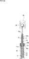
Figure 8] Figure 8 is a perspective view of the other end of a Bowden cable and a cable holding portion. - [
Figure 9] Figure 9 is an enlarged front view of a main section of the other end of the Bowden cable and the cable holding portion, being fixed to each other. - [
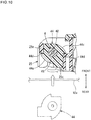
Figure 10] Figure 10 is a cross-sectional view taken along line X-X inFigure 9 . - As illustrated in
Figures 1 ,2 ,4 , and5 to 7 , vehicle doorlatch device 10 according to the present invention includesdoor latch mechanism 2, outside handle operation handle 3 (an example of an operation handle), Bowdencable 4,elastic cap 7 of a first embodiment (refer toFigures 2 ,4 , and6 ) orelastic cap 8 of a second embodiment (refer toFigures 5 and7 ). - Here, door
latch mechanism 2 is disposed in door 1 of a vehicle. Outsidehandle 3 is disposed on a vehicle exterior side of door 1. Bowdencable 4 includesouter cable 41 that transmits door opening operation ofoutside handle 3 to releaselever 24 described below ofdoor latch mechanism 2, andinner cable 42 inserted intoouter cable 41.Elastic cap 7 of the first embodiment andelastic cap 8 of the second embodiment prevent ingress of rainwater intoouter cable 41 in Bowdencable 4. - As illustrated in
Figures 1 and2 ,outside handle 3 is disposed abovedoor latch mechanism 2 in a vertical direction, for example. In another view,door latch mechanism 2 is disposed belowoutside handle 3 in the vertical direction, for example. - Door 1 is formed of
outer panel 11 on the vehicle exterior side andinner panel 12 on a vehicle interior side. Door 1 has a front end portion that is pivoted to a vehicle body side face to be openable and closable with a door hinge (not illustrated) having a rotating shaft with a vertical axis.Outer panel 11 is provided on its outer face withoutside handle 3.Outer panel 11 of door 1 has an inner face to whichdoor beam 13 extending in a longitudinal direction is fastened. - As illustrated in
Figure 3 ,door latch mechanism 2 has an engagementunit including latch 22 andratchet 23, various levers, andhousing 21. - Latch 22 is detachable from a striker S fastened to a vehicle body.
Ratchet 23 is detachable fromlatch 22. The various levers are directly or indirectly coupled toratchet 23.Housing 21 is made of synthetic resin to cover the various levers. The various levers include alsorelease lever 24. -
Release lever 24 is pivoted in a lower portion ofhousing 21.Terminal part 46 fastened to a downward end ofinner cable 42 of Bowdencable 4 is coupled tocoupling portion 24a projecting fromhousing 21 inrelease lever 24. This causes release lever 24 to receive door opening operation ofoutside handle 3 to operateratchet 23 for release. As a result, engagement betweenratchet 23 andlatch 22 is released to enable door 1 to be opened. -
Cable holding portion 25 for fixing an end portion ofouter cable 41 in Bowdencable 4 is integrally formed in a portion ofhousing 21, above release lever 24 (refer toFigures 3 and8 ). Structure ofcable holding portion 25 and the end portion ofouter cable 41 will be described below in detail. - As illustrated in
Figure 2 ,outside handle 3 is supported inhandle base 5 fixed to an inner face ofouter panel 11 to be capable of swinging outward about a shaft with a vertical axis.Lever 6 configured to operate together with door opening operation ofoutside handle 3 is pivoted inhandle base 5 to be able to turn aroundshaft 6a with an axis in a longitudinal direction through a predetermined angle, as illustrated inFigures 4 and5 .Terminal part 45 fastened to an upper end ofinner cable 42 is coupled tocoupling portion 6b being a turning end inlever 6, as illustrated inFigures 4 and5 . As described above, door opening operation ofoutside handle 3 is transmitted to releaselever 24 ofdoor latch mechanism 2 withlever 6 andinner cable 42. -
Bowden cable 4 includes flexibleouter cable 41, and flexibleinner cable 42 inserted intoouter cable 41. As illustrated inFigure 2 ,Bowden cable 4 is coupled at upper end (one end) tooutside handle 3, and at lower end (the other end) todoor latch mechanism 2.Bowden cable 4 extends, along the inner face ofouter panel 11, obliquely downward, forward from its upper end on anoutside handle 3 side, then turns upward, and extend downward to reach its lower end on adoor latch mechanism 2 side, in a form of being wired in door 1, as illustrated inFigures 1 and2 . - It is preferable to apply zinc plating to a surface of
inner cable 42. This prevents rust from occurring ininner cable 42 to enable smooth sliding to be acquired. - As illustrated in
Figures 1 and2 ,cushioning material 9 in a cylindrical shape is fitted ontoouter cable 41 overlapping withdoor beam 13 in door 1 in a direction toward inside and outside door 1 to prevent an abnormal sound from occurring. - As illustrated in
Figures 2 ,4 , and5 , one end upward ofouter cable 41 is fixed to holdingportion 5a ofhandle base 5 with handle-side end cap 43 in a cylindrical shape fastened to the one end upward. As illustrated inFigures 4 ,5 ,6A , and6B ,inner cable 42 extending upward from a tip of handle-side end cap 43 is coupled tocoupling portion 6b oflever 6 withterminal part 45 fastened to the tip.Terminal part 45 ofinner cable 42 may be configured to be directly coupled to a movable part ofoutside handle 4, instead of couplingportion 6b oflever 6. In this case,lever 6 is eliminated. - In the description below, a portion in
inner cable 42, extending upward from the tip of handle-side end cap 43, is referred to as handle-side projecting cable 42a (refer toFigures 4 ,5 ,6A ,6B ,7A , and7B ) for convenience of explanation. -
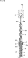
Elastic cap 7 made of rubber according to the first embodiment illustrated inFigure 4 , orelastic cap 8 made of rubber according to the second embodiment illustrated inFigure 5 , is fixed to handle-side end cap 43 fastened to one end ofouter cable 41. Each ofelastic caps outer cable 41 from the one end ofouter cable 41 by covering handle-side projecting cable 42a ofinner cable 42. Each ofelastic caps - As illustrated in
Figures 2 and8 , the other end downward ofouter cable 41 is fixed tocable holding portion 25 ofdoor latch mechanism 2 with door-latch-side end cap 44 fastened to the other end.Inner cable 42 extending downward from a tip (lower end) of door-latch-side end cap 44 is coupled to releaselever 24 ofdoor latch mechanism 2 withterminal part 46 fastened to the tip. - As illustrated in
Figures 8 to 10 ,cable holding portion 25 ofdoor latch mechanism 2 includes holdingportion 25a in a U-shape in plan view, with an open side facingrear panel 12a (refer toFigure 10 ) ofinner panel 12, to whichdoor latch mechanism 2 is fixed. Into holdingportion 25a, acentral pillar portion 44a in an oval shape in cross section of door-latch-side end cap 44 is inserted. Holdingportion 25a has an opening facing rearward, the opening being formed to be slightly narrow in width corresponding to a minor-axis dimension ofcentral pillar portion 44a. - In addition,
groove 25b in a semicircular shape in cross section is formed in a portion below holdingportion 25a incable holding portion 25, as illustrated inFigure 8 . Intogroove 25b,engagement flange 44b in the shape of a disk of door-latch-side end cap 44 is inserted from the rear in a vehicle toward the front in the vehicle, and is engaged. Engagement betweengroove 25b andengagement flange 44b reduces displacement of door-latch-side end cap 44 in a vehicle vertical direction with respect tocable holding portion 25. This causes the other end ofouter cable 41 to be reliably fixed tocable holding portion 25. - Further, a pair of
engagement projecting portions portion 25a incable holding portion 25. Rotatinghooks side end cap 44 are engaged with respectiveengagement projecting portions rotating hooks side end cap 44, and turns together with door-latch-side end cap 44. As illustrated inFigure 10 , a part of an outer peripheral surface of each of rotatinghooks claw portions - Door-latch-
side end cap 44 is fixed tocable holding portion 25 as follows. - First, door-latch-
side end cap 44 is set such that a major-axis ofcentral pillar portion 44a faces in a vehicle longitudinal direction like door-latch-side end cap 44 illustrated by a two-dot chain line in inFigure 10 . Next, door-latch-side end cap 44 is inserted intocable holding portion 25 from the rear in a vehicle toward the front. In this case, the insertion is performed such thatcentral pillar portion 44a is fitted into holdingportion 25a,engagement flange 44b is fitted intogroove 25b, androtating hooks engagement projecting portions - Subsequently, when door-latch-
side end cap 44 is turned together withouter cable 41 in a counterclockwise direction as viewed from vertically above, like door-latch-side end cap 44 illustrated by a solid line inFigure 10 , the arc face gradually increasing in radius of each of rotatinghooks engagement projecting portions side end cap 44 through a predetermined angle (90 degrees) is finished,claw portions rotating hooks engagement projecting portions Figure 10 . - As described above, displacement of
Bowden cable 4 in door-latch-side end cap 44 in its axial direction (longitudinal direction) is prevented by engagement ofengagement flange 44b withgroove 25b. In addition, turning ofBowden cable 4 around its axis is prevented by engagement ofengagement projecting portions respective claw portions outer cable 41 to be reliably fixed tocable holding portion 25 ofdoor latch mechanism 2. - As illustrated in
Figure 10 , an opened rear side ofcable holding portion 25 facesrear panel 12a while being close torear panel 12a ofinner panel 12. Thus, door-latch-side end cap 44 is not removed rearward from the opening ofcable holding portion 25, so thatcable holding portion 25 is reliably fixed. - Next,
elastic caps -
Figure 6A is a longitudinal sectional view of a main section ofoutside handle 3 according to the first embodiment in a non-operated state.Figure 6B is a longitudinal sectional view of a main section ofoutside handle 3 according to the first embodiment in an operated state. -
Elastic cap 7 according to the first embodiment includes: fittingportion 71 increased in diameter with a length of about 1/4 ofelastic cap 7, formed on its lower side in its longitudinal direction (vertical direction); andcover portion 72 in a cylindrical shape with a small diameter and a length of about 3/4 ofelastic cap 7, formed on its upper side while extending in a movement direction of handle-side projecting cable 42a. - Fitting
portion 71 is fixed to an upper end of handle-side end cap 43 when annular projectingportion 71a formed on its inner peripheral surface is fitted ontoannular groove 43a formed in an outer periphery of an upper end portion of handle-side end cap 43. When fittingportion 71 is fitted and fixed onto handle-side end cap 43, handle-side projecting cable 42a ofinner cable 42 is covered withcover portion 72 in its movement direction. Handle-side projecting cable 42a passes through the inside ofcover portion 72 to extend fromoutlet 72a being the tip ofcover portion 72, and thenterminal part 45 at a tip of handle-side projecting cable 42a is coupled tocoupling portion 6b oflever 6. It is preferable to set an inner diameter ofcover portion 72 so as to be slightly larger than an outside diameter of handle-side projecting cable 42a. This causes a minute clearance between an inner peripheral surface ofcover portion 72 and an outer peripheral surface of handle-side projecting cable 42a, so that the first embodiment can reduce ingress of rainwater fromoutlet 72a ofcover portion 72 to a minimum. As a result, the first embodiment prevents ingress of rainwater intoouter cable 41. - In an inner peripheral surface of the boundary between
fitting portion 71 andcover portion 72, there is provided annular projectingportion 73 that is always in close contact with a part of the surface of handle-side projecting cable 42a ofinner cable 42 throughout its whole circumference in the circumferential direction. In other words, betweenfitting portion 71 andcover portion 72, there is provided annular projecting portion 73 (an example of a part of cover portion 72) that is always in close contact with a part of the surface of handle-side projecting cable 42a ofinner cable 42 throughout its whole circumference in the circumferential direction. In still other words, above fittingportion 71 or belowcover portion 72, there is provided annular projectingportion 73 that is always in close contact with a part of the surface of handle-side projecting cable 42a ofinner cable 42 throughout its whole circumference in the circumferential direction. As a result, wheninner cable 42 vertically moves through the inside ofcover portion 72 ofelastic cap 7 in response to door opening operation ofoutside handle 3,inner cable 42 vertically slides while an outer peripheral surface ofinner cable 42 is in close contact with annular projectingportion 73. Thus, the first embodiment reliably prevents ingress of rainwater intoelastic cap 7. This enables the first embodiment to reliably prevent ingress of rainwater intoouter cable 41. It is preferable to poursilicon grease 100 into a space formed betweenfitting portion 71 and the upper end of handle-side end cap 43. This enables the first embodiment to more reliably prevent ingress of rainwater intoouter cable 41 withsilicon grease 100. -
Figure 7A is a longitudinal sectional view of a main section ofoutside handle 3 according to the second embodiment in a non-operated state.Figure 7B is a longitudinal sectional view of a main section ofoutside handle 3 according to the second embodiment in an operated state. - In the description below of the second embodiment, a difference from the first embodiment will be described, and description of the same portion is eliminated. In the second embodiment, the same component and the like as those of the first embodiment are each basically designated by the same reference sign in the description below and in
Figures 7A and7B . -
Elastic cap 8 according to the second embodiment includes: fittingportion 81 increased in diameter with a length of about 1/4 ofelastic cap 8, formed on its lower side in its longitudinal direction (vertical direction); andcover portion 82 in a cylindrical shape and a bellows shape with a length of about 3/4 ofelastic cap 8, formed on its upper side while extending in a movement direction of handle-side projecting cable 42a. - Fitting
portion 81 is fixed to an upper end of handle-side end cap 43 when annular projectingportion 81a formed on its inner peripheral surface is fitted ontoannular groove 43a formed in an outer periphery of an upper end portion of handle-side end cap 43. - Handle-
side projecting cable 42a ofinner cable 42 passes through the inside ofcover portion 82 ofelastic cap 8 to project upward fromoutlet 82a being an upper end ofcover portion 82. Then, a portion in handle-side projecting cable 42a, passing throughoutlet 82a, is bonded with adhesive 200 tooutlet 82a so as to allow the inner periphery ofoutlet 82a to be completely sealed throughout its whole circumference in the circumferential direction. In another view,cover portion 82 includesoutlet 82a that completely seal a part of the surface of handle-side projecting cable 42a ofinner cable 42 throughout its whole circumference in the circumferential direction. As a result, wheninner cable 42 vertically moves in response to door opening operation ofoutside handle 3,cover portion 82 in a bellows shape vertically expands and contracts by following vertical motion ofinner cable 42. This enablesinner cable 42 to be vertically and smoothly moved. In addition,outlet 82a ofcover portion 82 is completely closed with adhesive 200 andinner cable 41, so that the second embodiment enables ingress of rainwater intoelastic cap 8 andouter cable 41 to be reliably prevented. It is preferable to poursilicon grease 100 into a space formed betweenfitting portion 81 and the upper end of handle-side end cap 43. This enables the second embodiment to more reliably prevent ingress of rainwater intoouter cable 41 withsilicon grease 100. - While several preferable forms of the present invention are shown in detail and described, it should be understood that various changes and modifications may be made without departing from the spirit and scope of claims attached.
-
- 1
- door
- 2
- door latch mechanism
- 3
- outside handle (operation handle)
- 4
- Bowden cable
- 5
- handle base
- 5a
- holding portion
- 6
- lever
- 6a
- shaft
- 6b
- coupling portion
- 7
- elastic cap
- 8
- elastic cap
- 9
- cushioning material
- 10
- vehicle door latch device
- 11
- outer panel
- 12
- inner panel
- 12a
- rear panel
- 13
- door beam
- 21
- housing
- 22
- latch
- 23
- ratchet
- 24
- release lever
- 24a
- coupling portion
- 25
- cable holding portion
- 25a
- holding portion
- 25b
- groove
- 25c
- engagement projecting portion
- 41
- outer cable
- 42
- inner cable
- 42a
- handle-side projecting cable
- 43
- handle-side end cap
- 43a
- annular groove
- 44
- door-latch-side end cap
- 44a
- central pillar portion
- 44b
- engagement flange
- 44c
- rotating hook
- 44d
- claw portion
- 45, 46
- terminal part
- 71
- fitting portion
- 71a
- annular projecting portion
- 72
- cover portion
- 72a
- outlet
- 73
- annular projecting portion
- 81
- fitting portion
- 81a
- annular projecting portion
- 82
- cover portion
- 82a
- outlet
- 100
- silicon grease
- 200
- adhesive
Claims (8)
- A vehicle door latch device comprising:an operation handle that is supported by a handle base provided in a door;a door latch mechanism that maintains said door in a closed state;a Bowden cable including an outer cable that is fixed at one end to said handle base and at the other end to said door latch mechanism, and an inner cable that is inserted into said outer cable while being coupled at one end to said operation handle and at the other end to a release lever of said door latch mechanism; andan elastic cap that has a cover portion in a cylindrical shape, extending in a movement direction of said inner cable to cover said inner cable extending from the one end of said outer cable, and
- The vehicle door latch device according to claim 1, wherein
said elastic cap includes an annular projecting portion that is always in close contact with a part of said inner cable throughout its whole circumference in a circumferential direction. - The vehicle door latch device according to claim 2, wherein
said cover portion defines a minute clearance with the inner cable, and
said annular projecting portion is provided below said cover portion. - The vehicle door latch device according to claim 1, wherein
said cover portion is formed in a bellows shape capable of expansion and contraction in a movement direction of said inner cable, and
said cover portion has an outlet bonded with adhesive to said inner cable. - The vehicle door latch device according to claim 4, wherein
said outlet completely seals a part of said inner cable throughout its whole circumference in the circumferential direction when said outlet is bonded with adhesive to said inner cable. - The vehicle door latch device according to any one of claims 1 to 5, wherein
said elastic cap is filled with grease. - The vehicle door latch device according to claim 6, wherein
said elastic cap includes a fitting portion that is provided below said cover portion to cover said inner cable in a movement direction of said inner cable, and
said grease is filled in said fitting portion. - The vehicle door latch device according to any one of claims 1 to 7, wherein
said door latch mechanism includes a cable holding portion that fixes the other end of said outer cable, and
said cable holding portion fixes the other end of said outer cable while being engaged
with said Bowden cable in its axial direction and around its axis.
Applications Claiming Priority (2)
| Application Number | Priority Date | Filing Date | Title |
|---|---|---|---|
| JP2017140896A JP6704877B2 (en) | 2017-07-20 | 2017-07-20 | Vehicle door latch device |
| PCT/JP2017/038155 WO2019016970A1 (en) | 2017-07-20 | 2017-10-23 | Vehicle door latch device |
Publications (3)
| Publication Number | Publication Date |
|---|---|
| EP3663492A1 true EP3663492A1 (en) | 2020-06-10 |
| EP3663492A4 EP3663492A4 (en) | 2021-05-05 |
| EP3663492B1 EP3663492B1 (en) | 2025-04-09 |
Family
ID=65015667
Family Applications (1)
| Application Number | Title | Priority Date | Filing Date |
|---|---|---|---|
| EP17918303.3A Active EP3663492B1 (en) | 2017-07-20 | 2017-10-23 | Vehicle door latch device |
Country Status (5)
| Country | Link |
|---|---|
| US (1) | US11391071B2 (en) |
| EP (1) | EP3663492B1 (en) |
| JP (1) | JP6704877B2 (en) |
| CN (1) | CN110832157B (en) |
| WO (1) | WO2019016970A1 (en) |
Families Citing this family (5)
| Publication number | Priority date | Publication date | Assignee | Title |
|---|---|---|---|---|
| JP2020142735A (en) * | 2019-03-08 | 2020-09-10 | アイシン精機株式会社 | Vehicle cable |
| US11473343B2 (en) * | 2019-03-15 | 2022-10-18 | Ford Global Technologies, Llc | Actuator assembly for a vehicle door having a clip-on wiper for preventing infiltration of foreign matertal into the cable housing |
| US11239601B2 (en) | 2019-12-04 | 2022-02-01 | Kiekert Ag | Housing for use in motor vehicles |
| JP7516713B2 (en) * | 2020-10-06 | 2024-07-17 | 三井金属アクト株式会社 | Door closer device |
| US12371929B2 (en) * | 2023-03-08 | 2025-07-29 | Kiekert Ag | Securing arrangement on a motor vehicle door |
Family Cites Families (17)
| Publication number | Priority date | Publication date | Assignee | Title |
|---|---|---|---|---|
| JPS54159924A (en) * | 1978-06-09 | 1979-12-18 | Mitsui Mining & Smelting Co Ltd | Apparatus for preventing rainwater from entering automobile locking device |
| JPS5865312A (en) | 1981-10-15 | 1983-04-19 | Nissan Motor Co Ltd | Control cable |
| JPS63173512U (en) * | 1987-05-02 | 1988-11-10 | ||
| JPH041968U (en) * | 1990-04-20 | 1992-01-09 | ||
| US5809840A (en) * | 1995-02-14 | 1998-09-22 | Shimano, Inc. | Protective cap system for bicycle cable |
| US5765447A (en) * | 1996-03-29 | 1998-06-16 | W. L. Gore & Associates, Inc. | Mechanical cable system having a bellows seal |
| US5785152A (en) * | 1996-06-25 | 1998-07-28 | Shimano, Inc. | Lubricant-containing end cap for a bicycle control cable |
| JP3708719B2 (en) * | 1998-09-03 | 2005-10-19 | 株式会社大井製作所 | Door lock unit for automotive door closure device |
| JP3908436B2 (en) | 2000-03-31 | 2007-04-25 | 株式会社大井製作所 | Wire mounting structure for automotive locking device |
| DE10100636A1 (en) | 2001-01-09 | 2002-07-18 | Huf Huelsbeck & Fuerst Gmbh | Device for actuating a lock on a door or a flap, in particular in vehicles |
| JP3946535B2 (en) * | 2002-02-18 | 2007-07-18 | 株式会社大井製作所 | Operating force transmission member in door lock device |
| US8414038B2 (en) * | 2010-08-12 | 2013-04-09 | Nissan North America, Inc. | Vehicle door latch structure |
| GB2517348B (en) * | 2012-09-25 | 2015-09-23 | Jaguar Land Rover Ltd | Retractable handle arrangement |
| DE202014102033U1 (en) | 2014-04-30 | 2015-07-31 | BROSE SCHLIEßSYSTEME GMBH & CO. KG | Bowden |
| FR3022604B1 (en) * | 2014-06-18 | 2016-09-30 | U-Shin France Sas | SEALING DEVICE |
| JP6175523B1 (en) | 2016-02-09 | 2017-08-02 | 株式会社ホンダアクセス | Automotive floor protection structure |
| CN205976809U (en) * | 2016-08-08 | 2017-02-22 | 浙江吉利控股集团有限公司 | Automobile door lock act as go -between seal structure and automobile door lock and car |
-
2017
- 2017-07-20 JP JP2017140896A patent/JP6704877B2/en active Active
- 2017-10-23 EP EP17918303.3A patent/EP3663492B1/en active Active
- 2017-10-23 CN CN201780092808.9A patent/CN110832157B/en active Active
- 2017-10-23 WO PCT/JP2017/038155 patent/WO2019016970A1/en not_active Ceased
- 2017-10-23 US US16/629,696 patent/US11391071B2/en active Active
Also Published As
| Publication number | Publication date |
|---|---|
| US20210079695A1 (en) | 2021-03-18 |
| US11391071B2 (en) | 2022-07-19 |
| JP6704877B2 (en) | 2020-06-03 |
| CN110832157B (en) | 2021-12-07 |
| JP2019019618A (en) | 2019-02-07 |
| CN110832157A (en) | 2020-02-21 |
| EP3663492A4 (en) | 2021-05-05 |
| EP3663492B1 (en) | 2025-04-09 |
| WO2019016970A1 (en) | 2019-01-24 |
Similar Documents
| Publication | Publication Date | Title |
|---|---|---|
| EP3663492A1 (en) | Vehicle door latch device | |
| EP3214349B1 (en) | Dust seal | |
| US10100558B2 (en) | Locking aid drive for a motor vehicle lock | |
| WO2015136775A1 (en) | Door latch device for vehicle | |
| JP6682364B2 (en) | Locking device for housing unit and opening / closing body | |
| US20190093399A1 (en) | Actuator for fuel lid | |
| US20050166701A1 (en) | Bowden cable with a curved guide part | |
| KR20190008963A (en) | Car Locking Device | |
| US7216901B2 (en) | Operation force transmitting member for door lock apparatus | |
| JP2006240511A (en) | Steering cover | |
| US20160281771A1 (en) | Dust cover for ball joint | |
| US11358446B2 (en) | Slide door structure | |
| JP2017166247A (en) | Roller device | |
| WO2018047831A1 (en) | Container | |
| JP2003032853A (en) | Mounting structure of grommet | |
| WO2014162528A1 (en) | Hose coupling | |
| KR100879891B1 (en) | Switching device for towing hook mounting hole | |
| JP2002012044A (en) | Cap device | |
| US6802231B1 (en) | Closure member for an opening in an assembly, situated on a bicycle gear box | |
| JP2016030921A (en) | Vehicular door handle device | |
| JP7818126B1 (en) | Door hole cover mounting structure manufacturing method | |
| US20250027529A1 (en) | Mechanical control device with improved control cable coupling | |
| JP7128999B2 (en) | container | |
| JPWO2018151082A1 (en) | Filler pipe sleeve body and fuel supply portion constituting device | |
| EP3473789B1 (en) | Door handle for a motor vehicle |
Legal Events
| Date | Code | Title | Description |
|---|---|---|---|
| STAA | Information on the status of an ep patent application or granted ep patent |
Free format text: STATUS: THE INTERNATIONAL PUBLICATION HAS BEEN MADE |
|
| PUAI | Public reference made under article 153(3) epc to a published international application that has entered the european phase |
Free format text: ORIGINAL CODE: 0009012 |
|
| STAA | Information on the status of an ep patent application or granted ep patent |
Free format text: STATUS: REQUEST FOR EXAMINATION WAS MADE |
|
| 17P | Request for examination filed |
Effective date: 20200214 |
|
| AK | Designated contracting states |
Kind code of ref document: A1 Designated state(s): AL AT BE BG CH CY CZ DE DK EE ES FI FR GB GR HR HU IE IS IT LI LT LU LV MC MK MT NL NO PL PT RO RS SE SI SK SM TR |
|
| AX | Request for extension of the european patent |
Extension state: BA ME |
|
| DAV | Request for validation of the european patent (deleted) | ||
| DAX | Request for extension of the european patent (deleted) | ||
| REG | Reference to a national code |
Ipc: E05B0079200000 Ref country code: DE Ref legal event code: R079 Ref document number: 602017088883 Country of ref document: DE Free format text: PREVIOUS MAIN CLASS: E05B0077340000 Ipc: E05B0079200000 |
|
| A4 | Supplementary search report drawn up and despatched |
Effective date: 20210408 |
|
| RIC1 | Information provided on ipc code assigned before grant |
Ipc: E05B 79/20 20140101AFI20210331BHEP Ipc: E05B 77/34 20140101ALI20210331BHEP |
|
| RIN1 | Information on inventor provided before grant (corrected) |
Inventor name: KOYAMA, SAYAKA Inventor name: NAGAOKA, TOMOHARU |
|
| STAA | Information on the status of an ep patent application or granted ep patent |
Free format text: STATUS: EXAMINATION IS IN PROGRESS |
|
| 17Q | First examination report despatched |
Effective date: 20240524 |
|
| REG | Reference to a national code |
Ref country code: DE Ref legal event code: R079 Free format text: PREVIOUS MAIN CLASS: E05B0079200000 Ref document number: 602017088883 Country of ref document: DE Ipc: F16C0001100000 |
|
| GRAP | Despatch of communication of intention to grant a patent |
Free format text: ORIGINAL CODE: EPIDOSNIGR1 |
|
| STAA | Information on the status of an ep patent application or granted ep patent |
Free format text: STATUS: GRANT OF PATENT IS INTENDED |
|
| RIC1 | Information provided on ipc code assigned before grant |
Ipc: E05B 77/34 20140101ALI20241023BHEP Ipc: E05B 79/20 20140101ALI20241023BHEP Ipc: F16C 1/20 20060101ALI20241023BHEP Ipc: F16C 1/16 20060101ALI20241023BHEP Ipc: F16C 1/14 20060101ALI20241023BHEP Ipc: E05B 79/06 20140101ALI20241023BHEP Ipc: F16C 1/10 20060101AFI20241023BHEP |
|
| INTG | Intention to grant announced |
Effective date: 20241108 |
|
| P01 | Opt-out of the competence of the unified patent court (upc) registered |
Free format text: CASE NUMBER: APP_2696/2025 Effective date: 20250116 |
|
| GRAS | Grant fee paid |
Free format text: ORIGINAL CODE: EPIDOSNIGR3 |
|
| GRAA | (expected) grant |
Free format text: ORIGINAL CODE: 0009210 |
|
| STAA | Information on the status of an ep patent application or granted ep patent |
Free format text: STATUS: THE PATENT HAS BEEN GRANTED |
|
| AK | Designated contracting states |
Kind code of ref document: B1 Designated state(s): AL AT BE BG CH CY CZ DE DK EE ES FI FR GB GR HR HU IE IS IT LI LT LU LV MC MK MT NL NO PL PT RO RS SE SI SK SM TR |
|
| REG | Reference to a national code |
Ref country code: GB Ref legal event code: FG4D |
|
| REG | Reference to a national code |
Ref country code: CH Ref legal event code: EP |
|
| REG | Reference to a national code |
Ref country code: DE Ref legal event code: R096 Ref document number: 602017088883 Country of ref document: DE |
|
| REG | Reference to a national code |
Ref country code: IE Ref legal event code: FG4D |
|
| REG | Reference to a national code |
Ref country code: NL Ref legal event code: MP Effective date: 20250409 |
|
| PG25 | Lapsed in a contracting state [announced via postgrant information from national office to epo] |
Ref country code: NL Free format text: LAPSE BECAUSE OF FAILURE TO SUBMIT A TRANSLATION OF THE DESCRIPTION OR TO PAY THE FEE WITHIN THE PRESCRIBED TIME-LIMIT Effective date: 20250409 |
|
| REG | Reference to a national code |
Ref country code: AT Ref legal event code: MK05 Ref document number: 1783740 Country of ref document: AT Kind code of ref document: T Effective date: 20250409 |
|
| PG25 | Lapsed in a contracting state [announced via postgrant information from national office to epo] |
Ref country code: PT Free format text: LAPSE BECAUSE OF FAILURE TO SUBMIT A TRANSLATION OF THE DESCRIPTION OR TO PAY THE FEE WITHIN THE PRESCRIBED TIME-LIMIT Effective date: 20250811 Ref country code: FI Free format text: LAPSE BECAUSE OF FAILURE TO SUBMIT A TRANSLATION OF THE DESCRIPTION OR TO PAY THE FEE WITHIN THE PRESCRIBED TIME-LIMIT Effective date: 20250409 Ref country code: ES Free format text: LAPSE BECAUSE OF FAILURE TO SUBMIT A TRANSLATION OF THE DESCRIPTION OR TO PAY THE FEE WITHIN THE PRESCRIBED TIME-LIMIT Effective date: 20250409 |
|
| REG | Reference to a national code |
Ref country code: LT Ref legal event code: MG9D |
|
| PG25 | Lapsed in a contracting state [announced via postgrant information from national office to epo] |
Ref country code: GR Free format text: LAPSE BECAUSE OF FAILURE TO SUBMIT A TRANSLATION OF THE DESCRIPTION OR TO PAY THE FEE WITHIN THE PRESCRIBED TIME-LIMIT Effective date: 20250710 Ref country code: NO Free format text: LAPSE BECAUSE OF FAILURE TO SUBMIT A TRANSLATION OF THE DESCRIPTION OR TO PAY THE FEE WITHIN THE PRESCRIBED TIME-LIMIT Effective date: 20250709 |
|
| PG25 | Lapsed in a contracting state [announced via postgrant information from national office to epo] |
Ref country code: PL Free format text: LAPSE BECAUSE OF FAILURE TO SUBMIT A TRANSLATION OF THE DESCRIPTION OR TO PAY THE FEE WITHIN THE PRESCRIBED TIME-LIMIT Effective date: 20250409 |
|
| PG25 | Lapsed in a contracting state [announced via postgrant information from national office to epo] |
Ref country code: BG Free format text: LAPSE BECAUSE OF FAILURE TO SUBMIT A TRANSLATION OF THE DESCRIPTION OR TO PAY THE FEE WITHIN THE PRESCRIBED TIME-LIMIT Effective date: 20250409 |
|
| PG25 | Lapsed in a contracting state [announced via postgrant information from national office to epo] |
Ref country code: HR Free format text: LAPSE BECAUSE OF FAILURE TO SUBMIT A TRANSLATION OF THE DESCRIPTION OR TO PAY THE FEE WITHIN THE PRESCRIBED TIME-LIMIT Effective date: 20250409 |
|
| PG25 | Lapsed in a contracting state [announced via postgrant information from national office to epo] |
Ref country code: AT Free format text: LAPSE BECAUSE OF FAILURE TO SUBMIT A TRANSLATION OF THE DESCRIPTION OR TO PAY THE FEE WITHIN THE PRESCRIBED TIME-LIMIT Effective date: 20250409 |
|
| PGFP | Annual fee paid to national office [announced via postgrant information from national office to epo] |
Ref country code: FR Payment date: 20250908 Year of fee payment: 9 |
|
| PG25 | Lapsed in a contracting state [announced via postgrant information from national office to epo] |
Ref country code: RS Free format text: LAPSE BECAUSE OF FAILURE TO SUBMIT A TRANSLATION OF THE DESCRIPTION OR TO PAY THE FEE WITHIN THE PRESCRIBED TIME-LIMIT Effective date: 20250709 |
|
| PG25 | Lapsed in a contracting state [announced via postgrant information from national office to epo] |
Ref country code: IS Free format text: LAPSE BECAUSE OF FAILURE TO SUBMIT A TRANSLATION OF THE DESCRIPTION OR TO PAY THE FEE WITHIN THE PRESCRIBED TIME-LIMIT Effective date: 20250809 |
|
| PG25 | Lapsed in a contracting state [announced via postgrant information from national office to epo] |
Ref country code: LV Free format text: LAPSE BECAUSE OF FAILURE TO SUBMIT A TRANSLATION OF THE DESCRIPTION OR TO PAY THE FEE WITHIN THE PRESCRIBED TIME-LIMIT Effective date: 20250409 |
|
| REG | Reference to a national code |
Ref country code: DE Ref legal event code: R097 Ref document number: 602017088883 Country of ref document: DE |
|
| PG25 | Lapsed in a contracting state [announced via postgrant information from national office to epo] |
Ref country code: DK Free format text: LAPSE BECAUSE OF FAILURE TO SUBMIT A TRANSLATION OF THE DESCRIPTION OR TO PAY THE FEE WITHIN THE PRESCRIBED TIME-LIMIT Effective date: 20250409 Ref country code: SM Free format text: LAPSE BECAUSE OF FAILURE TO SUBMIT A TRANSLATION OF THE DESCRIPTION OR TO PAY THE FEE WITHIN THE PRESCRIBED TIME-LIMIT Effective date: 20250409 |
|
| PG25 | Lapsed in a contracting state [announced via postgrant information from national office to epo] |
Ref country code: CZ Free format text: LAPSE BECAUSE OF FAILURE TO SUBMIT A TRANSLATION OF THE DESCRIPTION OR TO PAY THE FEE WITHIN THE PRESCRIBED TIME-LIMIT Effective date: 20250409 |
|
| PG25 | Lapsed in a contracting state [announced via postgrant information from national office to epo] |
Ref country code: EE Free format text: LAPSE BECAUSE OF FAILURE TO SUBMIT A TRANSLATION OF THE DESCRIPTION OR TO PAY THE FEE WITHIN THE PRESCRIBED TIME-LIMIT Effective date: 20250409 |
|
| PG25 | Lapsed in a contracting state [announced via postgrant information from national office to epo] |
Ref country code: SK Free format text: LAPSE BECAUSE OF FAILURE TO SUBMIT A TRANSLATION OF THE DESCRIPTION OR TO PAY THE FEE WITHIN THE PRESCRIBED TIME-LIMIT Effective date: 20250409 Ref country code: RO Free format text: LAPSE BECAUSE OF FAILURE TO SUBMIT A TRANSLATION OF THE DESCRIPTION OR TO PAY THE FEE WITHIN THE PRESCRIBED TIME-LIMIT Effective date: 20250409 |
|
| PG25 | Lapsed in a contracting state [announced via postgrant information from national office to epo] |
Ref country code: IT Free format text: LAPSE BECAUSE OF FAILURE TO SUBMIT A TRANSLATION OF THE DESCRIPTION OR TO PAY THE FEE WITHIN THE PRESCRIBED TIME-LIMIT Effective date: 20250409 |
|
| PLBE | No opposition filed within time limit |
Free format text: ORIGINAL CODE: 0009261 |
|
| STAA | Information on the status of an ep patent application or granted ep patent |
Free format text: STATUS: NO OPPOSITION FILED WITHIN TIME LIMIT |
|
| REG | Reference to a national code |
Ref country code: CH Ref legal event code: L10 Free format text: ST27 STATUS EVENT CODE: U-0-0-L10-L00 (AS PROVIDED BY THE NATIONAL OFFICE) Effective date: 20260218 |
|
| 26N | No opposition filed |
Effective date: 20260112 |