EP3663440A1 - A device for making polymer fibre for a system of the spunbond and/or melt-blown type - Google Patents
A device for making polymer fibre for a system of the spunbond and/or melt-blown type Download PDFInfo
- Publication number
- EP3663440A1 EP3663440A1 EP19211983.2A EP19211983A EP3663440A1 EP 3663440 A1 EP3663440 A1 EP 3663440A1 EP 19211983 A EP19211983 A EP 19211983A EP 3663440 A1 EP3663440 A1 EP 3663440A1
- Authority
- EP
- European Patent Office
- Prior art keywords
- porous element
- distribution pipe
- melt
- spunbond
- polymer
- Prior art date
- Legal status (The legal status is an assumption and is not a legal conclusion. Google has not performed a legal analysis and makes no representation as to the accuracy of the status listed.)
- Pending
Links
Images


Classifications
-
- D—TEXTILES; PAPER
- D01—NATURAL OR MAN-MADE THREADS OR FIBRES; SPINNING
- D01D—MECHANICAL METHODS OR APPARATUS IN THE MANUFACTURE OF ARTIFICIAL FILAMENTS, THREADS, FIBRES, BRISTLES OR RIBBONS
- D01D5/00—Formation of filaments, threads, or the like
- D01D5/08—Melt spinning methods
- D01D5/098—Melt spinning methods with simultaneous stretching
- D01D5/0985—Melt spinning methods with simultaneous stretching by means of a flowing gas (e.g. melt-blowing)
-
- D—TEXTILES; PAPER
- D01—NATURAL OR MAN-MADE THREADS OR FIBRES; SPINNING
- D01D—MECHANICAL METHODS OR APPARATUS IN THE MANUFACTURE OF ARTIFICIAL FILAMENTS, THREADS, FIBRES, BRISTLES OR RIBBONS
- D01D4/00—Spinnerette packs; Cleaning thereof
-
- B—PERFORMING OPERATIONS; TRANSPORTING
- B29—WORKING OF PLASTICS; WORKING OF SUBSTANCES IN A PLASTIC STATE IN GENERAL
- B29C—SHAPING OR JOINING OF PLASTICS; SHAPING OF MATERIAL IN A PLASTIC STATE, NOT OTHERWISE PROVIDED FOR; AFTER-TREATMENT OF THE SHAPED PRODUCTS, e.g. REPAIRING
- B29C48/00—Extrusion moulding, i.e. expressing the moulding material through a die or nozzle which imparts the desired form; Apparatus therefor
- B29C48/03—Extrusion moulding, i.e. expressing the moulding material through a die or nozzle which imparts the desired form; Apparatus therefor characterised by the shape of the extruded material at extrusion
- B29C48/05—Filamentary, e.g. strands
-
- B—PERFORMING OPERATIONS; TRANSPORTING
- B29—WORKING OF PLASTICS; WORKING OF SUBSTANCES IN A PLASTIC STATE IN GENERAL
- B29C—SHAPING OR JOINING OF PLASTICS; SHAPING OF MATERIAL IN A PLASTIC STATE, NOT OTHERWISE PROVIDED FOR; AFTER-TREATMENT OF THE SHAPED PRODUCTS, e.g. REPAIRING
- B29C48/00—Extrusion moulding, i.e. expressing the moulding material through a die or nozzle which imparts the desired form; Apparatus therefor
- B29C48/25—Component parts, details or accessories; Auxiliary operations
- B29C48/30—Extrusion nozzles or dies
- B29C48/345—Extrusion nozzles comprising two or more adjacently arranged ports, for simultaneously extruding multiple strands, e.g. for pelletising
-
- D—TEXTILES; PAPER
- D01—NATURAL OR MAN-MADE THREADS OR FIBRES; SPINNING
- D01D—MECHANICAL METHODS OR APPARATUS IN THE MANUFACTURE OF ARTIFICIAL FILAMENTS, THREADS, FIBRES, BRISTLES OR RIBBONS
- D01D1/00—Treatment of filament-forming or like material
- D01D1/06—Feeding liquid to the spinning head
-
- D—TEXTILES; PAPER
- D01—NATURAL OR MAN-MADE THREADS OR FIBRES; SPINNING
- D01D—MECHANICAL METHODS OR APPARATUS IN THE MANUFACTURE OF ARTIFICIAL FILAMENTS, THREADS, FIBRES, BRISTLES OR RIBBONS
- D01D1/00—Treatment of filament-forming or like material
- D01D1/10—Filtering or de-aerating the spinning solution or melt
- D01D1/106—Filtering
-
- D—TEXTILES; PAPER
- D01—NATURAL OR MAN-MADE THREADS OR FIBRES; SPINNING
- D01D—MECHANICAL METHODS OR APPARATUS IN THE MANUFACTURE OF ARTIFICIAL FILAMENTS, THREADS, FIBRES, BRISTLES OR RIBBONS
- D01D4/00—Spinnerette packs; Cleaning thereof
- D01D4/02—Spinnerettes
- D01D4/025—Melt-blowing or solution-blowing dies
-
- D—TEXTILES; PAPER
- D01—NATURAL OR MAN-MADE THREADS OR FIBRES; SPINNING
- D01D—MECHANICAL METHODS OR APPARATUS IN THE MANUFACTURE OF ARTIFICIAL FILAMENTS, THREADS, FIBRES, BRISTLES OR RIBBONS
- D01D4/00—Spinnerette packs; Cleaning thereof
- D01D4/06—Distributing spinning solution or melt to spinning nozzles
-
- D—TEXTILES; PAPER
- D01—NATURAL OR MAN-MADE THREADS OR FIBRES; SPINNING
- D01D—MECHANICAL METHODS OR APPARATUS IN THE MANUFACTURE OF ARTIFICIAL FILAMENTS, THREADS, FIBRES, BRISTLES OR RIBBONS
- D01D4/00—Spinnerette packs; Cleaning thereof
- D01D4/08—Supporting spinnerettes or other parts of spinnerette packs
-
- D—TEXTILES; PAPER
- D04—BRAIDING; LACE-MAKING; KNITTING; TRIMMINGS; NON-WOVEN FABRICS
- D04H—MAKING TEXTILE FABRICS, e.g. FROM FIBRES OR FILAMENTARY MATERIAL; FABRICS MADE BY SUCH PROCESSES OR APPARATUS, e.g. FELTS, NON-WOVEN FABRICS; COTTON-WOOL; WADDING ; NON-WOVEN FABRICS FROM STAPLE FIBRES, FILAMENTS OR YARNS, BONDED WITH AT LEAST ONE WEB-LIKE MATERIAL DURING THEIR CONSOLIDATION
- D04H1/00—Non-woven fabrics formed wholly or mainly of staple fibres or like relatively short fibres
- D04H1/40—Non-woven fabrics formed wholly or mainly of staple fibres or like relatively short fibres from fleeces or layers composed of fibres without existing or potential cohesive properties
- D04H1/54—Non-woven fabrics formed wholly or mainly of staple fibres or like relatively short fibres from fleeces or layers composed of fibres without existing or potential cohesive properties by welding together the fibres, e.g. by partially melting or dissolving
- D04H1/56—Non-woven fabrics formed wholly or mainly of staple fibres or like relatively short fibres from fleeces or layers composed of fibres without existing or potential cohesive properties by welding together the fibres, e.g. by partially melting or dissolving in association with fibre formation, e.g. immediately following extrusion of staple fibres
-
- D—TEXTILES; PAPER
- D01—NATURAL OR MAN-MADE THREADS OR FIBRES; SPINNING
- D01F—CHEMICAL FEATURES IN THE MANUFACTURE OF ARTIFICIAL FILAMENTS, THREADS, FIBRES, BRISTLES OR RIBBONS; APPARATUS SPECIALLY ADAPTED FOR THE MANUFACTURE OF CARBON FILAMENTS
- D01F8/00—Conjugated, i.e. bi- or multicomponent, artificial filaments or the like; Manufacture thereof
- D01F8/04—Conjugated, i.e. bi- or multicomponent, artificial filaments or the like; Manufacture thereof from synthetic polymers
Definitions
- This invention concerns a device for making polymer fibre for a system of the spunbond and/or melt-blown type of the kind specified in the preamble of the first claim.
- this invention concerns a device adapted to enable the manufacturing of polymer fibres extruded by means of at least part of said device and designed to make TNT-type fabric, directly or indirectly.
- non-woven fabric As is known, non-woven fabric, or TNT, is an industrial product similar to a fabric, but which is obtained with methods other than weaving and knitting. Thus, in a non-woven fabric, the fibres have a random development, without identifying any orderly structure, while in a fabric, the fibres have two directions, which are prevalent and orthogonal to one another, usually known as the warp and weft.
- a plurality of products containing TNT are made depending on the manufacturing technique used, which is mainly related to the way in which the product itself is used.
- high-quality TNTs for hygiene- and sanitary-type products are distinguished from low-quality TNTs used above all for geotex.
- non-woven fabrics can essentially be divided into spunlace, spunbond, and melt-blown.
- Spunlace fabric undergoes processing, which gives the material omnidirectional strength. Due to this property and to the possibility of its being produced in various materials, such as viscose, polyester, cotton, polyamide and microfibre, and to the possible finishes, i.e. smooth or perforated, and to the multitude of smooth or printed colours, spunlace is recommended for the hygiene and sanitary sector, for the automotive and cosmetic sectors, and for industrial or disposable uses.
- Spunbond which is usually made with polypropylene, is a non-woven fabric, which can be used in a variety of ways in the agricultural, hygiene and sanitary, construction, furniture, mattress, and other related sectors.
- numerous finishes can be applied to Spunbond, such as printed, laminated, printed laminated in flexography and self-adhesive.
- the system essentially includes at least one inlet pipe for the polymer substance, an extrusion head for the polymer, a distributor or breaker plate for the polymer and a spinneret adapted to make the actual spunbond thread, which is deposited on a conveyor belt.
- the above-mentioned elements are each arranged correspondingly and adjacently to one another so as to enable the processing of the polymer and the distribution of the spunbond TNT.
- the polymer inside the inlet pipe is pushed under pressure and at a high temperature, usually above 200°C, towards the extrusion head.
- a pressurised control is generally carried out, for example, by means of a pressure switch, to guarantee the continuity of the thread coming out and the accuracy of the depositing process.
- the extrusion head distributes the polymer along a distribution surface through which the molten polymer reaches the distributor.
- a filter is present between the distributor, or breaker plate, and the extrusion head, which is composed of a sheet of steel, usually with a thickness varying between 0.8 and 1.6 mm, and including fine mesh, for example, with nominal dimensions ranging from 20 to 110 ⁇ m.
- the above-mentioned filter is essentially a stretched net.
- the molten polymer After its passage inside the filter, the molten polymer enters the distributor, which accompanies the polymer towards the spinneret where the polymer is extruded in fibres constituting the spunbond TNT.
- the filter has the purpose of blocking particles or pigments of polymer, which are not perfectly melted, or which are nonetheless larger and could block the TNT extrusion holes, which are extremely small, on entering the spinneret.
- Melt-blown TNT is made by means of specific spinnerets so as to obtain more sophisticated technical features than the previous TNTs.
- melt-blown fabric is characterised by fibres with higher filtering power, both for liquid and aeriform substances.
- Systems for producing melt-blown non-woven fabric are composed of a box that contains the device for making melt-blown fibre and all the parts needed for the process to work optimally. Furthermore, known systems also comprise an extrusion head and a distributor, and an air knife.
- the extrusion head and the distributor basically have the same features as the extrusion head and distributor used in spunbond technology and include a filter adapted to sieve the incoming polymer fluid.
- melt-blown devices usually already comprise a spinneret inside the distributor adapted to channel the polymer fibres towards the support.
- the support serves to direct the polymer fibre towards the air knife and it is arranged so as to direct the fibres from the breaker plate towards a hole comprised in a cusp.
- the air knife is composed of a casing wrapping the cusp of the melt-blown device so as to direct a flow of air, possibly non-turbulent, towards the hole of the cusp.
- the filter is usually effective, it can become blocked easily and quickly.
- the technical task underlying this invention is to develop a device for making polymer fibre for a system of the spunbond and/or melt-blown type, capable of essentially overcoming at least part of the drawbacks mentioned.
- the measures, values, shapes, and geometric references when associated with words like “about” or other similar terms such as “approximately” or “essentially”, are to be understood as except for measurement errors or inaccuracies owing to production and/or manufacturing errors and, above all, except for a slight divergence from the value, measure, shape, or geometric reference with which it is associated.
- these terms if associated with a value, preferably indicate a divergence of not more than 10% of the value.
- the number 1 indicates as a whole the device for making polymer fibre for a system of the spunbond and/or melt-blown type according to the invention.
- the device 1 is preferably included in a system for making TNT of the spunbond or melt-blown type.
- the system is preferably configured to make non-woven fabric based on spunbond or melt-blown technology or both in a combined manner.
- the latter essentially make sure that the molten polymer material is extruded by means of a plurality of holes with micrometric nominal dimensions adapted to distribute the polymer fibres guided towards a conveyor belt or to introduce the polymer fibres in a hole in a cusp, in contact with one or more air knives.
- the device 1 is preferably designed to perform the same functions as devices comprised in common spunbond and melt-blown systems and it is configured to receive and distribute the polymer material in the form of polymer fibre, as in the prior art.
- the device 1 comprises a number of elements of the prior art.
- the device 1 preferably includes at least one distributor 3. Furthermore, but not necessarily, the device 1 also includes an extrusion head 2.
- the extrusion head 2 is preferably essentially a common extrusion head, for example, known as a coat-hanger.
- the extrusion head 2 may already be part of the spunbond and/or melt-blown system and in this case, it may not be comprised in the device 1.
- the distributor 3 is preferably adapted to interact with the extrusion head 2.
- the extrusion head 2 is preferably adapted to guide a polymer fluid to the distributor 3.
- the extrusion head 2 preferably includes at least one main channel 20.
- the main channel 20 is a narrow opening or passage pipe with any shape or size and can thus be cylindrical or square compatibly with the other elements with which the main pipe 20 interfaces.
- the main channel 20 is preferably adapted to enable the passage of polymer fluid through the extrusion head 2.
- the main channel 20 is adapted to cause the polymer fluid to flow towards the distributor 3.
- the distributor 3 is adapted to distribute polymer fluid. Essentially, the distributor 3 preferably corresponds to a breaker-plate of the spunbond and/or melt-blown system.
- the distributor 3 preferably includes at least one distribution pipe 30.
- the distribution pipe 30 is preferably in fluidic connection with the main channel 20. Thus, it is adapted to distribute the polymer fluid.
- the distributor 30 distributes the polymer fluid to other components to make TNT, for example.
- both the main channel 20 and the distribution pipe 30 can define complex shapes. Furthermore, they can split in two and involve sub-channels to distribute the polymer fluid.
- the distributor can include a plurality of distribution pipes 30 arranged downstream of the main channel 20, each adapted to distribute smaller quantities of polymer fluid than the main channel 20.
- the distributor 3 preferably includes a plurality of distribution pipes 3.
- the device 1 includes filtering means 4.
- the filtering means 4 are preferably arranged, in general, upstream of the distribution pipe 30.
- the filtering means 4 are arranged between the main channel 20 and the distribution pipe 30 so as to filter the polymer fluid.
- the filtering means 4 in particular, preferably include a porous element 40.
- the porous element 40 is essentially structurally similar to a sponge.
- the porous element is not to be understood to be a soft and easily deformable element.
- the porous element is preferably defined, in terms of rigidity and hardness, by the materials and manufacturing methods, which distinguish it.
- the porous element 40 like the sponges, also includes a plurality of pores, which make the porous element 40 itself essentially uneven and anisotropic.
- the porous element 40 is preferably an element made with the sintering technique.
- the latter preferably comprises a plurality of non-rectilinear through channels having varying dimensions.
- dimensions refers to all of the dimensions, which contribute to the volumetric determination of the cavities or pores characterising the porous element 40.
- the filtering means 4 preferably comprise a plurality of pores, or cavities, defining the through channels when adjacent. In other words, the consistency of the pores creates the through channels for the polymer fluid.
- each of the pores preferably has a minimum porosity of 18 ⁇ m.
- the porous element 40 is preferably processed by sintering and thus, comprises a plurality of particles of the same mutually sintered material.
- the particles can thus be of any material, provided it is resistant to the passage of the polymer fluid.
- the porous element 40 comprises a metal material.
- the sintered particles can be of a different kind.
- the particles can be components chosen between balls or fragments.
- the porous element 40 can comprise fibres, which are mutually interwoven and sintered.
- the porous element 40 can include a first layer and a second layer.
- Such layers are preferably mutually overlapping and include the components and the fibres respectively as described previously.
- the first layer and the second layer are preferably adjacent to the extrusion head 2 and to the distributor respectively, or they are adjacent to the distributor 3 and to the extrusion head 2 respectively.
- sintering may occur in one layer only, both of particles and of fibres.
- the porous element 40 can thus be arranged between the extrusion head 2 and the distributor 3, or it can be housed in at least either the extrusion head 2 or the distributor 3.
- the porous element 40 is preferably housed inside the distributor 3.
- the porous element 40 can thus be made in a single piece with the distributor 3 or, preferably, it is removably available in the distributor 3.
- the distributor 3 preferably includes at least one seat 31.
- the seat 31 is substantially a tub inside which the porous element 40 can be placed.
- this seat 31 is preferably, arranged upstream of the distribution pipe 30. Therefore, when the distributor 3 is in contact with the extrusion head 2, the seat 31 is adjacent to the extrusion head 2 and arranged between the main channel 20 and the distribution pipe 30.
- the device 1 can include a single seat 31, as shown in Fig. 2 , or it can have a plurality of adjacent seats 31, as shown in Fig. 3 .
- the porous element 40 preferably has a complementary shape to part of the seat 31 and it is arranged removably inside the seat 31.
- the device 1 can comprise a plurality of porous elements 40, which can be introduced as pads inside the opportune seats.
- each seat 31 is adapted to house the porous element 40 so that the latter is spaced apart from the distribution pipe 30.
- the seat 31 is preferably configured to prevent adhesion between the filtering means 4 and the distribution pipes 30.
- the seat 31 preferably includes at least one housing 310 and support means 311.
- the housing 310 is preferably the portion of seat 31 adapted to completely house the porous element 40. Therefore, the latter has, in particular, a shape that is complementary to the housing 310.
- the support means 311 are preferably adapted to enable the support of the porous element 310 thereon, so that the latter stays in the housing 310 spaced apart from the distribution pipe or pipes 30.
- the support means 311 can include a support frame, arranged at the edges of the seat 31, as shown in Fig. 4 , or other spacer elements.
- the support means 311 can also include a plurality of elements arranged in the central zone of the seat 31 or along the extension of the seat 31. An example of this type is shown in Figs. 7-8 .
- the support means 311 are configured, above all, to prevent the filtering means 4 from being subjected to deformations, during normal operation of the device 1, such as to compromise the functionality thereof.
- the support means 311 can define localised support points or support lines, for example, transversal or longitudinal to the extension of the entire distributor 3, or breaker-plate, or they can also be defined by a grid of support lines, which are both longitudinal and transversal.
- the support means 311 are generally configured to create at least one separation space 32.
- the separation space 32 is preferably a portion of free space comprised between the porous element 40 and the distribution channel 30 defining a thickness thereof.
- the thickness of the separation space 32 is preferably at least equal to 500 ⁇ m.
- the separation space 32 ranges from 500 ⁇ m to 8 cm.
- the separation space 32 defines a thickness that is greater than or equal to the thickness of the porous element 40.
- the latter defines a thickness at least equal to 1.5 mm.
- the porous element 40 preferably defines thicknesses ranging from 1.5 mm to 10 mm.
- the pores of the porous element 4 preferably define a porosity ranging from 20 ⁇ m to 800 ⁇ m.
- the polymer fluid is preferably chosen from the following: polypropylene, polyester, nylon, cellulose, polyester or viscose.
- the device 1 can include a spinneret 5.
- the spinneret 5 can be included in the system of the spunbond and/or melt-blown type and configured to interact with the distributor 3.
- the spinneret 5 can be a separate element from the distributor 3, as in common spunbond systems, or it can be part of the distributor 3, as in common melt-blown systems.
- the spinneret 5 preferably comprises a plurality of holes 50.
- Such holes 50 are preferably in fluidic connection with the distribution pipe 30 and adapted to extrude polymer fibres.
- the holes 50 have diameters that can vary in size depending on the use for which they are intended.
- the holes 50 for a device 1 of a spunbond system are preferably smaller in size than the holes 50 for a device 1 of a melt-blown system.
- the device 1 filters it continuously, crushing almost all of the pigmented particles trapped inside the filtering means 4.
- the highly irregular conformation of the porous element 40 doesn't allow the polymer particles to be deposited and stratify, which does happen, on the other hand, with net filters of the prior art.
- the device for making polymer fibre for a system of the spunbond and/or melt-blown 1 type according to the invention results in important advantages.
- the device 1 prevents the filtering means from blocking by crushing, as described, most of the polymer particles crossing the porous element 40.
Abstract
Description
- This invention concerns a device for making polymer fibre for a system of the spunbond and/or melt-blown type of the kind specified in the preamble of the first claim.
- In other words, this invention concerns a device adapted to enable the manufacturing of polymer fibres extruded by means of at least part of said device and designed to make TNT-type fabric, directly or indirectly.
- As is known, non-woven fabric, or TNT, is an industrial product similar to a fabric, but which is obtained with methods other than weaving and knitting. Thus, in a non-woven fabric, the fibres have a random development, without identifying any orderly structure, while in a fabric, the fibres have two directions, which are prevalent and orthogonal to one another, usually known as the warp and weft.
- At present, a plurality of products containing TNT are made depending on the manufacturing technique used, which is mainly related to the way in which the product itself is used.
- In particular, high-quality TNTs for hygiene- and sanitary-type products are distinguished from low-quality TNTs used above all for geotex.
- From a technical point of view, non-woven fabrics can essentially be divided into spunlace, spunbond, and melt-blown.
- Spunlace fabric undergoes processing, which gives the material omnidirectional strength. Due to this property and to the possibility of its being produced in various materials, such as viscose, polyester, cotton, polyamide and microfibre, and to the possible finishes, i.e. smooth or perforated, and to the multitude of smooth or printed colours, spunlace is recommended for the hygiene and sanitary sector, for the automotive and cosmetic sectors, and for industrial or disposable uses.
- Spunbond, which is usually made with polypropylene, is a non-woven fabric, which can be used in a variety of ways in the agricultural, hygiene and sanitary, construction, furniture, mattress, and other related sectors. By means of an appropriate treatment, it is possible to make a series of highly specific products for each sector: fluorescent, soft calendered, anti-mite, fireproof, anti-bacterial, antistatic, anti-UV and others. Furthermore, numerous finishes can be applied to Spunbond, such as printed, laminated, printed laminated in flexography and self-adhesive.
- Systems for producing non-woven spunbond fabric are traditionally made up of components, as shown in
Fig. 5 . - In particular, the system essentially includes at least one inlet pipe for the polymer substance, an extrusion head for the polymer, a distributor or breaker plate for the polymer and a spinneret adapted to make the actual spunbond thread, which is deposited on a conveyor belt.
- The above-mentioned elements are each arranged correspondingly and adjacently to one another so as to enable the processing of the polymer and the distribution of the spunbond TNT.
- More specifically, the polymer inside the inlet pipe is pushed under pressure and at a high temperature, usually above 200°C, towards the extrusion head. In this respect, a pressurised control is generally carried out, for example, by means of a pressure switch, to guarantee the continuity of the thread coming out and the accuracy of the depositing process.
- The extrusion head distributes the polymer along a distribution surface through which the molten polymer reaches the distributor. A filter is present between the distributor, or breaker plate, and the extrusion head, which is composed of a sheet of steel, usually with a thickness varying between 0.8 and 1.6 mm, and including fine mesh, for example, with nominal dimensions ranging from 20 to 110 µm. Thus, the above-mentioned filter is essentially a stretched net.
- After its passage inside the filter, the molten polymer enters the distributor, which accompanies the polymer towards the spinneret where the polymer is extruded in fibres constituting the spunbond TNT.
- More specifically, the filter has the purpose of blocking particles or pigments of polymer, which are not perfectly melted, or which are nonetheless larger and could block the TNT extrusion holes, which are extremely small, on entering the spinneret. Melt-blown TNT is made by means of specific spinnerets so as to obtain more sophisticated technical features than the previous TNTs. In fact, melt-blown fabric is characterised by fibres with higher filtering power, both for liquid and aeriform substances.
- Systems for producing melt-blown non-woven fabric are composed of a box that contains the device for making melt-blown fibre and all the parts needed for the process to work optimally. Furthermore, known systems also comprise an extrusion head and a distributor, and an air knife.
- The extrusion head and the distributor basically have the same features as the extrusion head and distributor used in spunbond technology and include a filter adapted to sieve the incoming polymer fluid. However, melt-blown devices usually already comprise a spinneret inside the distributor adapted to channel the polymer fibres towards the support.
- The support serves to direct the polymer fibre towards the air knife and it is arranged so as to direct the fibres from the breaker plate towards a hole comprised in a cusp. Whereas, the air knife is composed of a casing wrapping the cusp of the melt-blown device so as to direct a flow of air, possibly non-turbulent, towards the hole of the cusp.
- The prior art described here comprises a few important drawbacks.
- In particular, although the filter is usually effective, it can become blocked easily and quickly.
- In particular, such functional deviation is extremely important for polymers with a dark pigmentation, the particles of which are initially larger than the lighter colours.
- Furthermore, regular systems, which adopt the described filter, risk exploding due to increases in pressure inside the extrusion head deriving from the accumulation of polymer.
- Besides obviously being relevant in terms of safety, this drawback is also relevant in terms of efficiency and costs of the system, which, when subject to overpressure, necessarily needs to be stopped for cleaning or to replace the filter.
- In this situation, the technical task underlying this invention is to develop a device for making polymer fibre for a system of the spunbond and/or melt-blown type, capable of essentially overcoming at least part of the drawbacks mentioned.
- In the context of said technical task, it is an important purpose of the invention to obtain a device that enables the polymer accumulations to be significantly reduced in the extrusion head, without losing the efficiency required for the regular execution of the TNT manufacturing process.
- It is another important purpose of the invention to produce a device for making polymer fibre for a system of the spunbond and/or melt-blown type that is safe, enabling the prevention, or at least the significant reduction, of instances of excess pressure, which can result in the device's breaking.
- Consequently, it is a further task of the invention to produce a device for making polymer fibre for a system of the spunbond and/or melt-blown type, which enables a reduction in losses of time and profits caused by the device's blocking.
- The technical task and the specified purposes are achieved by a device for making polymer fibre for a system of the spunbond and/or melt-blown type, as claimed in the attached
claim 1. - Preferred technical solutions are highlighted in the dependent claims.
- The features and advantages of the invention are clarified below by the detailed description of preferred embodiments of the invention, with reference to the accompanying drawings, wherein:
-
Fig. 1 shows a cross-section view of a device for making polymer fibre for a system of the spunbond type according to the invention; -
Fig. 2 illustrates a cross-section view of a device for making polymer fibre for a system of the melt-blown type according to the invention; -
Fig. 3 is a perspective view of a device for making polymer fibre for a system of the melt-blown type according to the invention with a seat; -
Fig. 4 represents a perspective view of a device for making polymer fibre for a system of the melt-blown type according to the invention with a plurality of seats; -
Fig. 5 shows the detail of a distributor of a device for making polymer fibre for a system of the spunbond and/or melt-blown type according to the invention comparable to a breaker plate, wherein the separation space between the porous element and the distribution pipes is highlighted; and -
Fig. 6 illustrates a cross-section view of a device for making TNT of the spunbond type of the prior art; -
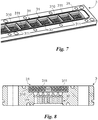
Fig. 7 is a perspective view of a device for making polymer fibre for a system of the melt-blown type according to the invention with a plurality of seats, wherein the support means are arranged in the central zone, along the longitudinal extension of the seats; and -
Fig. 8 represents the detail of a distributor of a device for making polymer fibre for a system of the spunbond and/or melt-blown type according to the invention comparable to a breaker plate, wherein the separation space between the porous element and the distribution pipes is highlighted and wherein the support means are arranged in the central zone, along the longitudinal extension of the seat. - In this document, the measures, values, shapes, and geometric references (such as perpendicularity and parallelism), when associated with words like "about" or other similar terms such as "approximately" or "essentially", are to be understood as except for measurement errors or inaccuracies owing to production and/or manufacturing errors and, above all, except for a slight divergence from the value, measure, shape, or geometric reference with which it is associated. For example, these terms, if associated with a value, preferably indicate a divergence of not more than 10% of the value.
- Furthermore, when used, terms such as "first", "second", "higher", "lower", "main" and "secondary" do not necessarily identify an order, a priority relationship, or a relative position, but can simply be used to more clearly distinguish between the different components.
- Unless otherwise stated, the measurements and data reported in this text shall be considered as performed in International Standard Atmosphere ICAO (ISO 2533:1975).
- With reference to the Figures, the
number 1 indicates as a whole the device for making polymer fibre for a system of the spunbond and/or melt-blown type according to the invention. - Thus, the
device 1 is preferably included in a system for making TNT of the spunbond or melt-blown type. - The system is preferably configured to make non-woven fabric based on spunbond or melt-blown technology or both in a combined manner. The latter essentially make sure that the molten polymer material is extruded by means of a plurality of holes with micrometric nominal dimensions adapted to distribute the polymer fibres guided towards a conveyor belt or to introduce the polymer fibres in a hole in a cusp, in contact with one or more air knives.
- The stated technique is known in the current state of the art.
- In fact, the
device 1 is preferably designed to perform the same functions as devices comprised in common spunbond and melt-blown systems and it is configured to receive and distribute the polymer material in the form of polymer fibre, as in the prior art. - In fact, the
device 1 comprises a number of elements of the prior art. - The
device 1 preferably includes at least onedistributor 3. Furthermore, but not necessarily, thedevice 1 also includes anextrusion head 2. - The
extrusion head 2 is preferably essentially a common extrusion head, for example, known as a coat-hanger. However, theextrusion head 2 may already be part of the spunbond and/or melt-blown system and in this case, it may not be comprised in thedevice 1. Nevertheless, thedistributor 3 is preferably adapted to interact with theextrusion head 2. - The
extrusion head 2 is preferably adapted to guide a polymer fluid to thedistributor 3. Thus, theextrusion head 2 preferably includes at least onemain channel 20. - The
main channel 20 is a narrow opening or passage pipe with any shape or size and can thus be cylindrical or square compatibly with the other elements with which themain pipe 20 interfaces. - The
main channel 20 is preferably adapted to enable the passage of polymer fluid through theextrusion head 2. In particular, themain channel 20 is adapted to cause the polymer fluid to flow towards thedistributor 3. - The
distributor 3 is adapted to distribute polymer fluid. Essentially, thedistributor 3 preferably corresponds to a breaker-plate of the spunbond and/or melt-blown system. - Thus, the
distributor 3 preferably includes at least onedistribution pipe 30. - The
distribution pipe 30 is preferably in fluidic connection with themain channel 20. Thus, it is adapted to distribute the polymer fluid. In detail, thedistributor 30 distributes the polymer fluid to other components to make TNT, for example. - As shown in
Fig. 1 , and as present in some devices of the prior art, both themain channel 20 and thedistribution pipe 30 can define complex shapes. Furthermore, they can split in two and involve sub-channels to distribute the polymer fluid. In other words, the distributor can include a plurality ofdistribution pipes 30 arranged downstream of themain channel 20, each adapted to distribute smaller quantities of polymer fluid than themain channel 20. Above all, in melt-blown type systems, thedistributor 3 preferably includes a plurality ofdistribution pipes 3. - In any case, advantageously and unlike the prior art, the
device 1 includes filtering means 4. - The filtering means 4 are preferably arranged, in general, upstream of the
distribution pipe 30. In particular, the filtering means 4 are arranged between themain channel 20 and thedistribution pipe 30 so as to filter the polymer fluid. - The filtering means 4, in particular, preferably include a
porous element 40. - The
porous element 40 is essentially structurally similar to a sponge. In this sense, the porous element is not to be understood to be a soft and easily deformable element. On the contrary, the porous element is preferably defined, in terms of rigidity and hardness, by the materials and manufacturing methods, which distinguish it. - However, the
porous element 40, like the sponges, also includes a plurality of pores, which make theporous element 40 itself essentially uneven and anisotropic. - In particular, the
porous element 40 is preferably an element made with the sintering technique. - Due to the manufacturing process, the latter preferably comprises a plurality of non-rectilinear through channels having varying dimensions.
- The term dimensions refers to all of the dimensions, which contribute to the volumetric determination of the cavities or pores characterising the
porous element 40. - More specifically, the filtering means 4 preferably comprise a plurality of pores, or cavities, defining the through channels when adjacent. In other words, the consistency of the pores creates the through channels for the polymer fluid.
- Furthermore, each of the pores preferably has a minimum porosity of 18 µm.
- As said previously, the
porous element 40 is preferably processed by sintering and thus, comprises a plurality of particles of the same mutually sintered material. - The particles can thus be of any material, provided it is resistant to the passage of the polymer fluid. For example, the
porous element 40 comprises a metal material. Furthermore, the sintered particles can be of a different kind. - For example, in a first embodiment, the particles can be components chosen between balls or fragments.
- In a second embodiment, the
porous element 40 can comprise fibres, which are mutually interwoven and sintered. - In a third embodiment, the
porous element 40 can include a first layer and a second layer. Such layers are preferably mutually overlapping and include the components and the fibres respectively as described previously. In detail, the first layer and the second layer are preferably adjacent to theextrusion head 2 and to the distributor respectively, or they are adjacent to thedistributor 3 and to theextrusion head 2 respectively. - Furthermore, sintering may occur in one layer only, both of particles and of fibres.
- The
porous element 40 can thus be arranged between theextrusion head 2 and thedistributor 3, or it can be housed in at least either theextrusion head 2 or thedistributor 3. - The
porous element 40 is preferably housed inside thedistributor 3. - The
porous element 40 can thus be made in a single piece with thedistributor 3 or, preferably, it is removably available in thedistributor 3. - Therefore, the
distributor 3 preferably includes at least oneseat 31. - The
seat 31 is substantially a tub inside which theporous element 40 can be placed. Thus, thisseat 31 is preferably, arranged upstream of thedistribution pipe 30. Therefore, when thedistributor 3 is in contact with theextrusion head 2, theseat 31 is adjacent to theextrusion head 2 and arranged between themain channel 20 and thedistribution pipe 30. - Thus, the
device 1 can include asingle seat 31, as shown inFig. 2 , or it can have a plurality ofadjacent seats 31, as shown inFig. 3 . - Nonetheless, the
porous element 40 preferably has a complementary shape to part of theseat 31 and it is arranged removably inside theseat 31. - Thus, if there are
multiple seats 31, thedevice 1 can comprise a plurality ofporous elements 40, which can be introduced as pads inside the opportune seats. - Advantageously, in a preferred, but non-exclusive, embodiment, each
seat 31 is adapted to house theporous element 40 so that the latter is spaced apart from thedistribution pipe 30. In particular, and especially when thedistributor 3 includes a plurality ofdistribution pipes 30, theseat 31 is preferably configured to prevent adhesion between the filtering means 4 and thedistribution pipes 30. - In this respect, the
seat 31 preferably includes at least onehousing 310 and support means 311. - The
housing 310 is preferably the portion ofseat 31 adapted to completely house theporous element 40. Therefore, the latter has, in particular, a shape that is complementary to thehousing 310. - The support means 311 are preferably adapted to enable the support of the
porous element 310 thereon, so that the latter stays in thehousing 310 spaced apart from the distribution pipe orpipes 30. - Therefore, the support means 311 can include a support frame, arranged at the edges of the
seat 31, as shown inFig. 4 , or other spacer elements. The support means 311 can also include a plurality of elements arranged in the central zone of theseat 31 or along the extension of theseat 31. An example of this type is shown inFigs. 7-8 . - In this case, the support means 311 are configured, above all, to prevent the filtering means 4 from being subjected to deformations, during normal operation of the
device 1, such as to compromise the functionality thereof. - Essentially, the support means 311 can define localised support points or support lines, for example, transversal or longitudinal to the extension of the
entire distributor 3, or breaker-plate, or they can also be defined by a grid of support lines, which are both longitudinal and transversal. - The support means 311 are generally configured to create at least one
separation space 32. - The
separation space 32 is preferably a portion of free space comprised between theporous element 40 and thedistribution channel 30 defining a thickness thereof. - The thickness of the
separation space 32 is preferably at least equal to 500 µm. - Even more preferably, the
separation space 32 ranges from 500 µm to 8 cm. - Preferably, but not necessarily, the
separation space 32 defines a thickness that is greater than or equal to the thickness of theporous element 40. In the preferred embodiment, the latter defines a thickness at least equal to 1.5 mm. Even more specifically, theporous element 40 preferably defines thicknesses ranging from 1.5 mm to 10 mm. - Furthermore, in the preferred embodiment, the pores of the
porous element 4 preferably define a porosity ranging from 20 µm to 800 µm. - The polymer fluid is preferably chosen from the following: polypropylene, polyester, nylon, cellulose, polyester or viscose.
- In conclusion, the
device 1 can include aspinneret 5. Or, thespinneret 5 can be included in the system of the spunbond and/or melt-blown type and configured to interact with thedistributor 3. - In fact, the
spinneret 5 can be a separate element from thedistributor 3, as in common spunbond systems, or it can be part of thedistributor 3, as in common melt-blown systems. - In any case, the
spinneret 5 preferably comprises a plurality ofholes 50.Such holes 50 are preferably in fluidic connection with thedistribution pipe 30 and adapted to extrude polymer fibres. - Opportunely, the
holes 50 have diameters that can vary in size depending on the use for which they are intended. - For example, the
holes 50 for adevice 1 of a spunbond system are preferably smaller in size than theholes 50 for adevice 1 of a melt-blown system. - The operation of the device for making polymer fibre for a system of the spunbond and/or melt-blown 1 type, described previously in structural terms, is similar to that of regular systems.
- However, during the polymer fluid's passage, the
device 1 filters it continuously, crushing almost all of the pigmented particles trapped inside the filtering means 4. - In fact, the highly irregular conformation of the
porous element 40 doesn't allow the polymer particles to be deposited and stratify, which does happen, on the other hand, with net filters of the prior art. - The device for making polymer fibre for a system of the spunbond and/or melt-blown 1 type according to the invention results in important advantages.
- In fact, the
device 1 prevents the filtering means from blocking by crushing, as described, most of the polymer particles crossing theporous element 40. - Thus, an additional advantage comes from the fact that the costs of maintaining the system are significantly reduced, both in terms of money and time, increasing the efficiency and safety of the systems on which the
devices 1 are installed. - The invention is subject to variations falling within the scope of the inventive concept defined by the claims.
- In such context, all of the details can be replaced by equivalent elements and any materials, shapes and sizes can be used.
Claims (15)
- A device (1) for making polymer fibre for a system of the spunbond and/or melt-blown type comprising:- a distributor (3) including at least one distribution pipe (30) adapted to distribute said polymer fluid,- filtering means (4) arranged upstream of said distribution pipe (30) so as to filter said polymer fluid,and characterised in that- said filtering means (4) include a porous element (40) defining a plurality of non-rectilinear passage channels of varying sizes.
- A device (1) according to claim 1, wherein said distributor (3) includes at least one seat (31) arranged upstream of said distribution pipe (30), said filtering means (4) are at least partially housed in said seat (31), and said seat (31) is configured to space apart said filtering means (4) and said distribution pipe (30).
- A device (1) according to claim 1, wherein said distributor (3) is a breaker-plate of said system of the spunbond and/or melt-blown type.
- A device (1) according to any one of the preceding claims, comprising an extrusion head (2) including at least one main channel (20) adapted to enable the passage of polymer fluid through said extrusion head (2), said distribution pipe (30) being in fluidic connection with said main channel (20) and said filtering means (4) being arranged between said main channel (20) and said distribution pipe (30) so as to filter said polymer fluid.
- A device (1) according to the preceding claim, wherein said seat (31) is adjacent to said extrusion head (2) and arranged between said main channel (20) and said distribution pipe (30).
- A device (1) according to any one of the preceding claims, wherein said porous element (40) comprises a plurality of pores defining said through channels when adjacent and with a minimum porosity of 18 µm.
- A device (1) according to any one of the preceding claims, wherein said porous element (40) comprises a plurality of sintered particles.
- A device (1) according to any one of the preceding claims, wherein said porous element (40) comprises a metal material.
- A device (1) according to claim 4, wherein said particles are components chosen between balls or fragments.
- A device (1) according to any one of the preceding claims, wherein said porous element (40) comprises mutually interwoven and sintered fibres.
- A device (1) according to claims 6 and 7, wherein said porous element (40) comprises a plurality of mutually overlapping layers, respectively including said components and said fibres or only one layer comprising both said components and said mutually sintered fibres.
- A device (1) according to any one of the preceding claims, wherein said seat (31) includes a housing (310) adapted to house said porous element (40) and support means (311) adapted to space apart said porous element (40) from said at least one distribution pipe (30) so as to create a separation space (32) defining a minimum thickness of 500 µm.
- A device (1) according to any one of the preceding claims, wherein said support means (311) include a plurality of elements arranged in the central zone or along the extension of said seat (31) so as to prevent said filtering means (4) from being subjected to deformations, during normal operation of said device (1), which are such as to compromise the functionality thereof.
- A device (1) according to any one of the preceding claims, comprises at least one spinneret (5) including a plurality of holes (50) each in fluidic connection with said distribution pipe (30) and adapted to extrude polymer fibres.
- A system of the spunbond and/or melt-blown type, comprising a device (1) according to any one of the preceding claims.
Applications Claiming Priority (2)
| Application Number | Priority Date | Filing Date | Title |
|---|---|---|---|
| IT102018000010823A IT201800010823A1 (en) | 2018-12-05 | 2018-12-05 | DEVICE FOR MAKING POLYMER FILAMENT FOR SPUNBOND AND / OR MELTBLOWN PLANT |
| IT102019000010044A IT201900010044A1 (en) | 2019-06-25 | 2019-06-25 | DEVICE FOR THE REALIZATION OF POLYMER FILAMENT FOR SPUNBOND AND / OR MELTBLOWN SYSTEM |
Publications (1)
| Publication Number | Publication Date |
|---|---|
| EP3663440A1 true EP3663440A1 (en) | 2020-06-10 |
Family
ID=68653432
Family Applications (1)
| Application Number | Title | Priority Date | Filing Date |
|---|---|---|---|
| EP19211983.2A Pending EP3663440A1 (en) | 2018-12-05 | 2019-11-28 | A device for making polymer fibre for a system of the spunbond and/or melt-blown type |
Country Status (4)
| Country | Link |
|---|---|
| US (1) | US20200181805A1 (en) |
| EP (1) | EP3663440A1 (en) |
| CN (1) | CN111270318A (en) |
| WO (1) | WO2020115620A1 (en) |
Families Citing this family (2)
| Publication number | Priority date | Publication date | Assignee | Title |
|---|---|---|---|---|
| CN113679166A (en) * | 2021-08-31 | 2021-11-23 | 深圳市丰和信新材料有限公司 | Making process of cosmetic brush filaments |
| JP2023089929A (en) * | 2021-12-16 | 2023-06-28 | フラテッリ チェカット ミラノ エス.アール.エル. | Polymer distributor for spunbond and/or melt-blown type implant |
Citations (5)
| Publication number | Priority date | Publication date | Assignee | Title |
|---|---|---|---|---|
| US3788486A (en) * | 1971-09-30 | 1974-01-29 | Minnesota Mining & Mfg | Filter |
| US4661249A (en) * | 1985-01-28 | 1987-04-28 | Metallurgical Industries, Inc. | Prefilter device for polymeric material |
| EP0220324A1 (en) * | 1985-04-27 | 1987-05-06 | Smc Corporation | Polymer filtering apparatus |
| EP0455492A1 (en) * | 1990-05-03 | 1991-11-06 | Pall Corporation | Filters for polymer spinneret assemblies and their manufacture |
| WO2006020109A2 (en) * | 2004-07-16 | 2006-02-23 | Hills, Inc. | Forming shaped fiber fabrics |
Family Cites Families (7)
| Publication number | Priority date | Publication date | Assignee | Title |
|---|---|---|---|---|
| US1558626A (en) * | 1923-08-02 | 1925-10-27 | Soie Artificielle De Tubize Sa | Drawing-frame carrier for the spinning of artificial textile materials |
| US3475527A (en) * | 1967-12-11 | 1969-10-28 | Monsanto Co | Process for destroying melt crystalline order in fiber-forming polymers |
| US3729279A (en) * | 1971-06-24 | 1973-04-24 | Mott Metallurg Corp | Spinnerette with head filter |
| US3965010A (en) * | 1975-02-04 | 1976-06-22 | E. I. Du Pont De Nemours And Company | Metal filter for melt spinning packs |
| CA1094957A (en) * | 1976-04-23 | 1981-02-03 | Harry M. Kennard | Filter medium |
| US6182732B1 (en) * | 1998-03-03 | 2001-02-06 | Nordson Corporation | Apparatus for the manufacture of nonwoven webs and laminates including means to move the spinning assembly |
| JP2009536693A (en) * | 2006-05-11 | 2009-10-15 | エーリコン テクスティル ゲゼルシャフト ミット ベシュレンクテル ハフツング ウント コンパニー コマンディートゲゼルシャフト | Apparatus for melt spinning row filaments |
-
2019
- 2019-11-28 WO PCT/IB2019/060274 patent/WO2020115620A1/en active Application Filing
- 2019-11-28 EP EP19211983.2A patent/EP3663440A1/en active Pending
- 2019-12-03 US US16/701,589 patent/US20200181805A1/en not_active Abandoned
- 2019-12-05 CN CN201911233486.2A patent/CN111270318A/en active Pending
Patent Citations (5)
| Publication number | Priority date | Publication date | Assignee | Title |
|---|---|---|---|---|
| US3788486A (en) * | 1971-09-30 | 1974-01-29 | Minnesota Mining & Mfg | Filter |
| US4661249A (en) * | 1985-01-28 | 1987-04-28 | Metallurgical Industries, Inc. | Prefilter device for polymeric material |
| EP0220324A1 (en) * | 1985-04-27 | 1987-05-06 | Smc Corporation | Polymer filtering apparatus |
| EP0455492A1 (en) * | 1990-05-03 | 1991-11-06 | Pall Corporation | Filters for polymer spinneret assemblies and their manufacture |
| WO2006020109A2 (en) * | 2004-07-16 | 2006-02-23 | Hills, Inc. | Forming shaped fiber fabrics |
Non-Patent Citations (1)
| Title |
|---|
| RIGBY W R ET AL: "POROUS SINTERED METAL AND CERAMIC FILTERS FOR THE PRODUCTION OF MAN-MADE POLYMER FIBERS", CHEMICAL FIBERS INTERNATIONAL,, vol. 51, no. 1, 1 February 2001 (2001-02-01), pages 57/58, XP001004968, ISSN: 0340-3343 * |
Also Published As
| Publication number | Publication date |
|---|---|
| US20200181805A1 (en) | 2020-06-11 |
| WO2020115620A1 (en) | 2020-06-11 |
| CN111270318A (en) | 2020-06-12 |
Similar Documents
| Publication | Publication Date | Title |
|---|---|---|
| EP3663440A1 (en) | A device for making polymer fibre for a system of the spunbond and/or melt-blown type | |
| US9856591B2 (en) | Nonwoven fabric | |
| RU2553003C2 (en) | Nonwoven bulky and method of its production | |
| EP2398633B1 (en) | Multi-layer, fluid transmissive fiber structures containing nanofibers and a method of manufacturing such structures | |
| EP1228270B1 (en) | Improved nonwoven fabric with high cd elongation and method of making same | |
| JP4593394B2 (en) | Multi-component spunbond nonwoven fabric, method for producing the same and method for using the same | |
| US10857042B2 (en) | Nonwoven laminate | |
| IT201900010044A1 (en) | DEVICE FOR THE REALIZATION OF POLYMER FILAMENT FOR SPUNBOND AND / OR MELTBLOWN SYSTEM | |
| WO2017032778A1 (en) | Cleaning textile | |
| US20060277731A1 (en) | Method for stitch-bonding or finishing a material web by means of hidrodynamic needling, and product produced according to this method | |
| US11578429B2 (en) | Cusp die for producing melt-blown non-woven fabric | |
| JP6265775B2 (en) | Liquid holding material | |
| US10071327B2 (en) | Filter medium | |
| EP4206369A1 (en) | Plant for making spunbond type polymeric filament | |
| DE19953717C2 (en) | Fiber mat | |
| JP2013071058A (en) | Filter and filtering device | |
| EP4198177A1 (en) | Distributor of polymer for spunbond and/or melt-blown type apparatus | |
| EP3360993A1 (en) | Disposable absorbent surface protection mat | |
| IT201800010823A1 (en) | DEVICE FOR MAKING POLYMER FILAMENT FOR SPUNBOND AND / OR MELTBLOWN PLANT | |
| KR101282785B1 (en) | Manufacturing method of melt blown nonwoven fabric having high bulkiness | |
| BR102022022771A2 (en) | POLYMER DISTRIBUTOR FOR CONTINUOUS FILAMENT AND/OR BLOW FORMATION TYPES SYSTEM | |
| EP2091779B1 (en) | Protective cover for a seat | |
| CN109476112A (en) | Tinkertoy module and its manufacturing method | |
| IT201800010822A1 (en) | PRODUCTION CHAIN FOR POLYMER FILAMENTS | |
| HU177212B (en) | Filter cloth and process for preparing thereof |
Legal Events
| Date | Code | Title | Description |
|---|---|---|---|
| PUAI | Public reference made under article 153(3) epc to a published international application that has entered the european phase |
Free format text: ORIGINAL CODE: 0009012 |
|
| STAA | Information on the status of an ep patent application or granted ep patent |
Free format text: STATUS: THE APPLICATION HAS BEEN PUBLISHED |
|
| AK | Designated contracting states |
Kind code of ref document: A1 Designated state(s): AL AT BE BG CH CY CZ DE DK EE ES FI FR GB GR HR HU IE IS IT LI LT LU LV MC MK MT NL NO PL PT RO RS SE SI SK SM TR |
|
| AX | Request for extension of the european patent |
Extension state: BA ME |
|
| STAA | Information on the status of an ep patent application or granted ep patent |
Free format text: STATUS: REQUEST FOR EXAMINATION WAS MADE |
|
| 17P | Request for examination filed |
Effective date: 20200715 |
|
| RBV | Designated contracting states (corrected) |
Designated state(s): AL AT BE BG CH CY CZ DE DK EE ES FI FR GB GR HR HU IE IS IT LI LT LU LV MC MK MT NL NO PL PT RO RS SE SI SK SM TR |