EP3663115A1 - Cooling duct of high voltage battery system of vehicle - Google Patents
Cooling duct of high voltage battery system of vehicle Download PDFInfo
- Publication number
- EP3663115A1 EP3663115A1 EP19158565.2A EP19158565A EP3663115A1 EP 3663115 A1 EP3663115 A1 EP 3663115A1 EP 19158565 A EP19158565 A EP 19158565A EP 3663115 A1 EP3663115 A1 EP 3663115A1
- Authority
- EP
- European Patent Office
- Prior art keywords
- inlet
- blocking wall
- outlet
- cooling duct
- duct
- Prior art date
- Legal status (The legal status is an assumption and is not a legal conclusion. Google has not performed a legal analysis and makes no representation as to the accuracy of the status listed.)
- Granted
Links
Images


Classifications
-
- B—PERFORMING OPERATIONS; TRANSPORTING
- B60—VEHICLES IN GENERAL
- B60K—ARRANGEMENT OR MOUNTING OF PROPULSION UNITS OR OF TRANSMISSIONS IN VEHICLES; ARRANGEMENT OR MOUNTING OF PLURAL DIVERSE PRIME-MOVERS IN VEHICLES; AUXILIARY DRIVES FOR VEHICLES; INSTRUMENTATION OR DASHBOARDS FOR VEHICLES; ARRANGEMENTS IN CONNECTION WITH COOLING, AIR INTAKE, GAS EXHAUST OR FUEL SUPPLY OF PROPULSION UNITS IN VEHICLES
- B60K1/00—Arrangement or mounting of electrical propulsion units
-
- B—PERFORMING OPERATIONS; TRANSPORTING
- B60—VEHICLES IN GENERAL
- B60L—PROPULSION OF ELECTRICALLY-PROPELLED VEHICLES; SUPPLYING ELECTRIC POWER FOR AUXILIARY EQUIPMENT OF ELECTRICALLY-PROPELLED VEHICLES; ELECTRODYNAMIC BRAKE SYSTEMS FOR VEHICLES IN GENERAL; MAGNETIC SUSPENSION OR LEVITATION FOR VEHICLES; MONITORING OPERATING VARIABLES OF ELECTRICALLY-PROPELLED VEHICLES; ELECTRIC SAFETY DEVICES FOR ELECTRICALLY-PROPELLED VEHICLES
- B60L58/00—Methods or circuit arrangements for monitoring or controlling batteries or fuel cells, specially adapted for electric vehicles
- B60L58/10—Methods or circuit arrangements for monitoring or controlling batteries or fuel cells, specially adapted for electric vehicles for monitoring or controlling batteries
- B60L58/24—Methods or circuit arrangements for monitoring or controlling batteries or fuel cells, specially adapted for electric vehicles for monitoring or controlling batteries for controlling the temperature of batteries
- B60L58/26—Methods or circuit arrangements for monitoring or controlling batteries or fuel cells, specially adapted for electric vehicles for monitoring or controlling batteries for controlling the temperature of batteries by cooling
-
- H—ELECTRICITY
- H01—ELECTRIC ELEMENTS
- H01M—PROCESSES OR MEANS, e.g. BATTERIES, FOR THE DIRECT CONVERSION OF CHEMICAL ENERGY INTO ELECTRICAL ENERGY
- H01M10/00—Secondary cells; Manufacture thereof
- H01M10/60—Heating or cooling; Temperature control
- H01M10/65—Means for temperature control structurally associated with the cells
- H01M10/655—Solid structures for heat exchange or heat conduction
- H01M10/6552—Closed pipes transferring heat by thermal conductivity or phase transition, e.g. heat pipes
-
- B—PERFORMING OPERATIONS; TRANSPORTING
- B60—VEHICLES IN GENERAL
- B60R—VEHICLES, VEHICLE FITTINGS, OR VEHICLE PARTS, NOT OTHERWISE PROVIDED FOR
- B60R13/00—Elements for body-finishing, identifying, or decorating; Arrangements or adaptations for advertising purposes
- B60R13/08—Insulating elements, e.g. for sound insulation
- B60R13/0846—Insulating elements, e.g. for sound insulation for duct, cable or rod passages, e.g. between engine and passenger compartments
-
- H—ELECTRICITY
- H01—ELECTRIC ELEMENTS
- H01M—PROCESSES OR MEANS, e.g. BATTERIES, FOR THE DIRECT CONVERSION OF CHEMICAL ENERGY INTO ELECTRICAL ENERGY
- H01M10/00—Secondary cells; Manufacture thereof
- H01M10/60—Heating or cooling; Temperature control
- H01M10/61—Types of temperature control
- H01M10/613—Cooling or keeping cold
-
- H—ELECTRICITY
- H01—ELECTRIC ELEMENTS
- H01M—PROCESSES OR MEANS, e.g. BATTERIES, FOR THE DIRECT CONVERSION OF CHEMICAL ENERGY INTO ELECTRICAL ENERGY
- H01M10/00—Secondary cells; Manufacture thereof
- H01M10/60—Heating or cooling; Temperature control
- H01M10/62—Heating or cooling; Temperature control specially adapted for specific applications
- H01M10/625—Vehicles
-
- H—ELECTRICITY
- H01—ELECTRIC ELEMENTS
- H01M—PROCESSES OR MEANS, e.g. BATTERIES, FOR THE DIRECT CONVERSION OF CHEMICAL ENERGY INTO ELECTRICAL ENERGY
- H01M10/00—Secondary cells; Manufacture thereof
- H01M10/60—Heating or cooling; Temperature control
- H01M10/65—Means for temperature control structurally associated with the cells
- H01M10/656—Means for temperature control structurally associated with the cells characterised by the type of heat-exchange fluid
- H01M10/6567—Liquids
- H01M10/6568—Liquids characterised by flow circuits, e.g. loops, located externally to the cells or cell casings
-
- B—PERFORMING OPERATIONS; TRANSPORTING
- B60—VEHICLES IN GENERAL
- B60K—ARRANGEMENT OR MOUNTING OF PROPULSION UNITS OR OF TRANSMISSIONS IN VEHICLES; ARRANGEMENT OR MOUNTING OF PLURAL DIVERSE PRIME-MOVERS IN VEHICLES; AUXILIARY DRIVES FOR VEHICLES; INSTRUMENTATION OR DASHBOARDS FOR VEHICLES; ARRANGEMENTS IN CONNECTION WITH COOLING, AIR INTAKE, GAS EXHAUST OR FUEL SUPPLY OF PROPULSION UNITS IN VEHICLES
- B60K1/00—Arrangement or mounting of electrical propulsion units
- B60K2001/003—Arrangement or mounting of electrical propulsion units with means for cooling the electrical propulsion units
- B60K2001/005—Arrangement or mounting of electrical propulsion units with means for cooling the electrical propulsion units the electric storage means
-
- B—PERFORMING OPERATIONS; TRANSPORTING
- B60—VEHICLES IN GENERAL
- B60K—ARRANGEMENT OR MOUNTING OF PROPULSION UNITS OR OF TRANSMISSIONS IN VEHICLES; ARRANGEMENT OR MOUNTING OF PLURAL DIVERSE PRIME-MOVERS IN VEHICLES; AUXILIARY DRIVES FOR VEHICLES; INSTRUMENTATION OR DASHBOARDS FOR VEHICLES; ARRANGEMENTS IN CONNECTION WITH COOLING, AIR INTAKE, GAS EXHAUST OR FUEL SUPPLY OF PROPULSION UNITS IN VEHICLES
- B60K6/00—Arrangement or mounting of plural diverse prime-movers for mutual or common propulsion, e.g. hybrid propulsion systems comprising electric motors and internal combustion engines
- B60K6/20—Arrangement or mounting of plural diverse prime-movers for mutual or common propulsion, e.g. hybrid propulsion systems comprising electric motors and internal combustion engines the prime-movers consisting of electric motors and internal combustion engines, e.g. HEVs
- B60K6/22—Arrangement or mounting of plural diverse prime-movers for mutual or common propulsion, e.g. hybrid propulsion systems comprising electric motors and internal combustion engines the prime-movers consisting of electric motors and internal combustion engines, e.g. HEVs characterised by apparatus, components or means specially adapted for HEVs
- B60K6/28—Arrangement or mounting of plural diverse prime-movers for mutual or common propulsion, e.g. hybrid propulsion systems comprising electric motors and internal combustion engines the prime-movers consisting of electric motors and internal combustion engines, e.g. HEVs characterised by apparatus, components or means specially adapted for HEVs characterised by the electric energy storing means, e.g. batteries or capacitors
-
- B—PERFORMING OPERATIONS; TRANSPORTING
- B60—VEHICLES IN GENERAL
- B60L—PROPULSION OF ELECTRICALLY-PROPELLED VEHICLES; SUPPLYING ELECTRIC POWER FOR AUXILIARY EQUIPMENT OF ELECTRICALLY-PROPELLED VEHICLES; ELECTRODYNAMIC BRAKE SYSTEMS FOR VEHICLES IN GENERAL; MAGNETIC SUSPENSION OR LEVITATION FOR VEHICLES; MONITORING OPERATING VARIABLES OF ELECTRICALLY-PROPELLED VEHICLES; ELECTRIC SAFETY DEVICES FOR ELECTRICALLY-PROPELLED VEHICLES
- B60L2240/00—Control parameters of input or output; Target parameters
- B60L2240/40—Drive Train control parameters
- B60L2240/54—Drive Train control parameters related to batteries
- B60L2240/547—Voltage
-
- B—PERFORMING OPERATIONS; TRANSPORTING
- B60—VEHICLES IN GENERAL
- B60Y—INDEXING SCHEME RELATING TO ASPECTS CROSS-CUTTING VEHICLE TECHNOLOGY
- B60Y2200/00—Type of vehicle
- B60Y2200/90—Vehicles comprising electric prime movers
- B60Y2200/92—Hybrid vehicles
-
- B—PERFORMING OPERATIONS; TRANSPORTING
- B60—VEHICLES IN GENERAL
- B60Y—INDEXING SCHEME RELATING TO ASPECTS CROSS-CUTTING VEHICLE TECHNOLOGY
- B60Y2306/00—Other features of vehicle sub-units
- B60Y2306/05—Cooling
-
- B—PERFORMING OPERATIONS; TRANSPORTING
- B60—VEHICLES IN GENERAL
- B60Y—INDEXING SCHEME RELATING TO ASPECTS CROSS-CUTTING VEHICLE TECHNOLOGY
- B60Y2306/00—Other features of vehicle sub-units
- B60Y2306/09—Reducing noise
-
- B—PERFORMING OPERATIONS; TRANSPORTING
- B60—VEHICLES IN GENERAL
- B60Y—INDEXING SCHEME RELATING TO ASPECTS CROSS-CUTTING VEHICLE TECHNOLOGY
- B60Y2400/00—Special features of vehicle units
- B60Y2400/11—Electric energy storages
- B60Y2400/112—Batteries
-
- H—ELECTRICITY
- H01—ELECTRIC ELEMENTS
- H01M—PROCESSES OR MEANS, e.g. BATTERIES, FOR THE DIRECT CONVERSION OF CHEMICAL ENERGY INTO ELECTRICAL ENERGY
- H01M2220/00—Batteries for particular applications
- H01M2220/20—Batteries in motive systems, e.g. vehicle, ship, plane
-
- Y—GENERAL TAGGING OF NEW TECHNOLOGICAL DEVELOPMENTS; GENERAL TAGGING OF CROSS-SECTIONAL TECHNOLOGIES SPANNING OVER SEVERAL SECTIONS OF THE IPC; TECHNICAL SUBJECTS COVERED BY FORMER USPC CROSS-REFERENCE ART COLLECTIONS [XRACs] AND DIGESTS
- Y02—TECHNOLOGIES OR APPLICATIONS FOR MITIGATION OR ADAPTATION AGAINST CLIMATE CHANGE
- Y02E—REDUCTION OF GREENHOUSE GAS [GHG] EMISSIONS, RELATED TO ENERGY GENERATION, TRANSMISSION OR DISTRIBUTION
- Y02E60/00—Enabling technologies; Technologies with a potential or indirect contribution to GHG emissions mitigation
- Y02E60/10—Energy storage using batteries
-
- Y—GENERAL TAGGING OF NEW TECHNOLOGICAL DEVELOPMENTS; GENERAL TAGGING OF CROSS-SECTIONAL TECHNOLOGIES SPANNING OVER SEVERAL SECTIONS OF THE IPC; TECHNICAL SUBJECTS COVERED BY FORMER USPC CROSS-REFERENCE ART COLLECTIONS [XRACs] AND DIGESTS
- Y02—TECHNOLOGIES OR APPLICATIONS FOR MITIGATION OR ADAPTATION AGAINST CLIMATE CHANGE
- Y02T—CLIMATE CHANGE MITIGATION TECHNOLOGIES RELATED TO TRANSPORTATION
- Y02T10/00—Road transport of goods or passengers
- Y02T10/60—Other road transportation technologies with climate change mitigation effect
- Y02T10/70—Energy storage systems for electromobility, e.g. batteries
Definitions
- the present invention relates to a duct structure for cooling a high voltage battery system mounted within a vehicle, and more particularly, to a cooling duct of a high voltage battery system that prevents high frequency noise generated from the battery form being introduced into the vehicle through an intake duct.
- the vehicle includes a high voltage battery that supplies power to the motor and a cooling apparatus that effectively removes heat generated from the high voltage battery.
- a water cooling-type cooling method and an air cooling-type cooling method may be used to cool high voltage batteries.
- the air cooling-type cooling method is comparatively simple and lightweight and is thus more widely used.
- the air cooling-type cooling method requires an intake duct to suction air necessary to cool a high voltage battery, and an exhaust duct to exhaust air after cooling of the high voltage battery.
- the intake duct is open towards the interior of a vehicle to suction air from the interior of the vehicle
- the exhaust duct is open towards the outside of the vehicle to exhaust air to the outside of the vehicle.
- an inverter is used, and the inverter converts direct current (DC) to alternating current (AC) through rapid switching of a switching element.
- a current ripple is generated due to the switching action of the inverter and the generated current ripple current causes high frequency noise via a high voltage part, particularly, a high voltage battery system mounted within the interior of a vehicle.
- the high frequency noise When the high frequency noise is introduced into the interior of the vehicle through the intake duct, the high frequency noise causes passenger's displeasure and thus lowers marketability of the vehicle.
- the present invention provides a cooling duct of a high voltage battery system of a vehicle which may effectively prevent high frequency noise generated from a high voltage battery from being introduced into the interior of the vehicle through an intake duct to prevent passenger's displeasure and to enhance marketability of the vehicle.
- a cooling duct of a high voltage battery system of a vehicle may include a duct body that forms an inlet open towards the interior of the vehicle, an outlet formed at a side of the duct body opposite to the inlet to supply air introduced into the cooling duct through the inlet to a high voltage battery, and a blocking wall formed between the inlet and the outlet to restrict rectilinear communication between the inlet and the outlet while allowing air flow between the inlet and the outlet.
- the blocking wall may be formed to have a linear shape inclined relative to the inlet.
- the blocking wall may be formed to be inclined at an angle of about 35° to 55° relative to the inlet.
- the blocking wall may be spaced apart from the center of the inlet by a shortest distance of about 40 mm to 60 mm.
- the blocking wall may be arranged with a first end connected to an inner surface of the duct body and a second end spaced apart from the inner surface of the duct body.
- a depression may be formed between the blocking wall and the inlet of the duct body to form a curved air flow path from the inlet to the outlet.
- the depression of the duct body may be formed at a part of the duct body, where the blocking wall is spaced apart from the inner surface of the duct body. Accordingly, air introduced into the cooling duct through the inlet may flow along an S-type curve through the depression and the blocking wall.
- a sound-absorbing material passing air may be installed at the outlet of the duct body.
- vehicle or “vehicular” or other similar term as used herein is inclusive of motor vehicles in general such as passenger automobiles including sports utility vehicles (SUV), buses, trucks, various commercial vehicles, watercraft including a variety of boats and ships, aircraft, and the like, and includes hybrid vehicles, electric vehicles, plug-in hybrid electric vehicles, hydrogen-powered vehicles and other alternative fuel vehicles (e.g. fuels derived from resources other than petroleum).
- a hybrid vehicle is a vehicle that has two or more sources of power, for example both gasoline-powered and electric-powered vehicles.
- a cooling duct 11 of a high voltage battery system of a vehicle in accordance with one exemplary embodiment of the present invention may include a duct body 3 that forms an inlet 1 that is open towards the interior of the vehicle, an outlet 5 formed at a side of the duct body 3 opposite to the inlet 1 to supply air introduced into the cooling duct 11 through the inlet 1 to a high voltage battery 7, and a blocking wall 9 formed between the inlet 1 and the outlet 5 to restrict rectilinear communication between the inlet 1 and the outlet 5 while allowing air flow between the inlet 1 and the outlet 5.
- the cooling duct 11 in accordance with the present invention is an intake duct that suctions air from the interior of the vehicle to cool the high voltage battery 7.
- the blocking wall 9 may be disposed between the inlet 1 and the outlet 5 formed at the duct body 3 and thus may block high frequency noise having high linearity generated from the high voltage battery 7 to prevent the high frequency noise from flowing into the interior of the vehicle through the inlet 1.
- the blocking wall 9 may be formed to have a linear shape inclined relative to the inlet 1.
- the blocking wall 9 may be formed to have a linear shape inclined at an angle of about 35° to 55° relative to the inlet 1.
- the blocking wall 9 may be spaced apart from the center of the inlet 1 by a shortest distance of about 40 mm to 60 mm.
- the blocking wall 9 may be spaced apart from the inlet 1 by a designated distance, particularly, the blocking wall 9 may be arranged with a first end of the blocking wall 9, i.e., an upper end of the blocking wall 9, spaced apart from the center of the inlet 1 by a distance of about 50 mm.
- the first end of the blocking wall 9 may be connected to the inner surface of the duct body 3, and a second end of the blocking wall 9 may be spaced apart from the inner surface of the duct body 3.
- the upper end of the blocking wall 9 may be formed integrally with the duct body 3 to be connected to the inner surface of the duct body 3.
- the lower end of the blocking wall 9 may be spaced apart from the inner surface of the duct body 3 to form an air passage.
- a depression 13 (e.g., groove) may be formed between the blocking wall 9 and the inlet 1 of the duct body 3 and thus may form a curved air flow path from the inlet 1 to the outlet 5.
- the air is forced over the depression 13 and then under the blocking wall 9 in an S-shaped curve of a flow path toward the outlet 5.
- the depression 13 of the duct body 3 may be formed at the lower part of the duct body 3 where the blocking wall 9 is spaced apart from the inner surface of the duct body 3. Accordingly, air introduced into the cooling duct 11 through the inlet 1 may flow along an S-type curve through the depression 13 and the blocking wall 9.
- a sound-absorbing material 15 through which air may pass may be installed at the outlet 5 of the duct body 3.
- the sound-absorbing material 15, through which air may flow to the high frequency battery 7 through the outlet 5 may absorb noise from the high frequency battery 7.
- the sound-absorbing material 15 may be installed at the outlet 5 or therearound (e.g., around, surrounding the outlet 5), thus may more effectively prevent transmission of noise to the interior of the vehicle.
- a cooling duct of a high voltage battery system of a vehicle in accordance with the present invention may effectively prevent high frequency noise generated from a high voltage battery from being introduced into the interior of the vehicle through an intake duct, thus preventing passenger's displeasure and enhancing marketability of the vehicle.
Landscapes
- Engineering & Computer Science (AREA)
- Chemical & Material Sciences (AREA)
- Manufacturing & Machinery (AREA)
- General Chemical & Material Sciences (AREA)
- Electrochemistry (AREA)
- Chemical Kinetics & Catalysis (AREA)
- Mechanical Engineering (AREA)
- Transportation (AREA)
- Power Engineering (AREA)
- Sustainable Energy (AREA)
- Sustainable Development (AREA)
- Life Sciences & Earth Sciences (AREA)
- Physics & Mathematics (AREA)
- Acoustics & Sound (AREA)
- Combustion & Propulsion (AREA)
- Cooling, Air Intake And Gas Exhaust, And Fuel Tank Arrangements In Propulsion Units (AREA)
- Secondary Cells (AREA)
Abstract
Description
- The present invention relates to a duct structure for cooling a high voltage battery system mounted within a vehicle, and more particularly, to a cooling duct of a high voltage battery system that prevents high frequency noise generated from the battery form being introduced into the vehicle through an intake duct.
- In an environmentally friendly vehicle such as a hybrid vehicle, an electric vehicle, or a plug-in hybrid vehicle, driving force is generated by a motor. The vehicle includes a high voltage battery that supplies power to the motor and a cooling apparatus that effectively removes heat generated from the high voltage battery. Both a water cooling-type cooling method and an air cooling-type cooling method may be used to cool high voltage batteries. The air cooling-type cooling method is comparatively simple and lightweight and is thus more widely used. The air cooling-type cooling method requires an intake duct to suction air necessary to cool a high voltage battery, and an exhaust duct to exhaust air after cooling of the high voltage battery.
- In general, the intake duct is open towards the interior of a vehicle to suction air from the interior of the vehicle, and the exhaust duct is open towards the outside of the vehicle to exhaust air to the outside of the vehicle. To drive the motor using power of the above-described high voltage battery, an inverter is used, and the inverter converts direct current (DC) to alternating current (AC) through rapid switching of a switching element.
- A current ripple is generated due to the switching action of the inverter and the generated current ripple current causes high frequency noise via a high voltage part, particularly, a high voltage battery system mounted within the interior of a vehicle. When the high frequency noise is introduced into the interior of the vehicle through the intake duct, the high frequency noise causes passenger's displeasure and thus lowers marketability of the vehicle.
- The above description has been provided to aid in understanding of the background of the present invention and should not be interpreted as conventional technology known to those skilled in the art.
- Therefore, the present invention provides a cooling duct of a high voltage battery system of a vehicle which may effectively prevent high frequency noise generated from a high voltage battery from being introduced into the interior of the vehicle through an intake duct to prevent passenger's displeasure and to enhance marketability of the vehicle.
- In accordance with the present invention, the above and other objects can be accomplished by the provision of a cooling duct of a high voltage battery system of a vehicle that may include a duct body that forms an inlet open towards the interior of the vehicle, an outlet formed at a side of the duct body opposite to the inlet to supply air introduced into the cooling duct through the inlet to a high voltage battery, and a blocking wall formed between the inlet and the outlet to restrict rectilinear communication between the inlet and the outlet while allowing air flow between the inlet and the outlet.
- In particular, the blocking wall may be formed to have a linear shape inclined relative to the inlet. The blocking wall may be formed to be inclined at an angle of about 35° to 55° relative to the inlet. Additionally, the blocking wall may be spaced apart from the center of the inlet by a shortest distance of about 40 mm to 60 mm. The blocking wall may be arranged with a first end connected to an inner surface of the duct body and a second end spaced apart from the inner surface of the duct body.
- A depression may be formed between the blocking wall and the inlet of the duct body to form a curved air flow path from the inlet to the outlet. The depression of the duct body may be formed at a part of the duct body, where the blocking wall is spaced apart from the inner surface of the duct body. Accordingly, air introduced into the cooling duct through the inlet may flow along an S-type curve through the depression and the blocking wall. A sound-absorbing material passing air may be installed at the outlet of the duct body.
- The above and other objects, features and other advantages of the present invention will be more clearly understood from the following detailed description taken in conjunction with the accompanying drawings, in which:
-
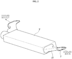
FIG. 1 is a view illustrating a cooling duct of a high voltage battery system of a vehicle in accordance with an exemplary embodiment of the present invention; -
FIG. 2 is a view illustrating the cooling duct in accordance with an exemplary embodiment of the present invention, mounted on the high voltage battery system; -
FIG. 3 is a cross-sectional view of the cooling duct ofFIG. 1 in accordance with an exemplary embodiment of the present invention; and -
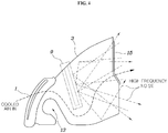
FIG. 4 is a view illustrating a high frequency noise blocking effect of the cooling duct ofFIG. 1 in accordance with an exemplary embodiment of the present invention. - It is understood that the term "vehicle" or "vehicular" or other similar term as used herein is inclusive of motor vehicles in general such as passenger automobiles including sports utility vehicles (SUV), buses, trucks, various commercial vehicles, watercraft including a variety of boats and ships, aircraft, and the like, and includes hybrid vehicles, electric vehicles, plug-in hybrid electric vehicles, hydrogen-powered vehicles and other alternative fuel vehicles (e.g. fuels derived from resources other than petroleum). As referred to herein, a hybrid vehicle is a vehicle that has two or more sources of power, for example both gasoline-powered and electric-powered vehicles.
- The terminology used herein is for the purpose of describing particular embodiments only and is not intended to be limiting of the invention. As used herein, the singular forms "a", "an" and "the" are intended to include the plural forms as well, unless the context clearly indicates otherwise. It will be further understood that the terms "comprises" and/or "comprising," when used in this specification, specify the presence of stated features, integers, steps, operations, elements, and/or components, but do not preclude the presence or addition of one or more other features, integers, steps, operations, elements, components, and/or groups thereof. As used herein, the term "and/or" includes any and all combinations of one or more of the associated listed items.
- Unless specifically stated or obvious from context, as used herein, the term "about" is understood as within a range of normal tolerance in the art, for example within 2 standard deviations of the mean. "About" can be understood as within 10%, 9%, 8%, 7%, 6%, 5%, 4%, 3%, 2%, 1%, 0.5%, 0.1%, 0.05%, or 0.01% of the stated value. Unless otherwise clear from the context, all numerical values provided herein are modified by the term "about."
- Reference will now be made in detail to the exemplary embodiments of the present invention, examples of which are illustrated in the accompanying drawings. Wherever possible, the same reference numbers will be used throughout the drawings to refer to the same or like parts.
- Referring to
FIGS. 1 to 4 , acooling duct 11 of a high voltage battery system of a vehicle in accordance with one exemplary embodiment of the present invention may include aduct body 3 that forms aninlet 1 that is open towards the interior of the vehicle, anoutlet 5 formed at a side of theduct body 3 opposite to theinlet 1 to supply air introduced into thecooling duct 11 through theinlet 1 to a high voltage battery 7, and a blockingwall 9 formed between theinlet 1 and theoutlet 5 to restrict rectilinear communication between theinlet 1 and theoutlet 5 while allowing air flow between theinlet 1 and theoutlet 5. - In other words, the
cooling duct 11 in accordance with the present invention is an intake duct that suctions air from the interior of the vehicle to cool the high voltage battery 7. The blockingwall 9 may be disposed between theinlet 1 and theoutlet 5 formed at theduct body 3 and thus may block high frequency noise having high linearity generated from the high voltage battery 7 to prevent the high frequency noise from flowing into the interior of the vehicle through theinlet 1. - In this exemplary embodiment, the blocking
wall 9 may be formed to have a linear shape inclined relative to theinlet 1. In other words, as exemplarily shown in these figures, the blockingwall 9 may be formed to have a linear shape inclined at an angle of about 35° to 55° relative to theinlet 1. Further, the blockingwall 9 may be spaced apart from the center of theinlet 1 by a shortest distance of about 40 mm to 60 mm. In particular, the blockingwall 9 may be spaced apart from theinlet 1 by a designated distance, particularly, the blockingwall 9 may be arranged with a first end of the blockingwall 9, i.e., an upper end of the blockingwall 9, spaced apart from the center of theinlet 1 by a distance of about 50 mm. - The first end of the blocking
wall 9 may be connected to the inner surface of theduct body 3, and a second end of the blockingwall 9 may be spaced apart from the inner surface of theduct body 3. As exemplarily shown inFIG. 3 , the upper end of the blockingwall 9 may be formed integrally with theduct body 3 to be connected to the inner surface of theduct body 3. The lower end of the blockingwall 9 may be spaced apart from the inner surface of theduct body 3 to form an air passage. - Additionally, a depression 13 (e.g., groove) may be formed between the blocking
wall 9 and theinlet 1 of theduct body 3 and thus may form a curved air flow path from theinlet 1 to theoutlet 5. In other words, after entering theinlet 1, the air is forced over thedepression 13 and then under the blockingwall 9 in an S-shaped curve of a flow path toward theoutlet 5. As exemplarily shown inFIG. 3 , thedepression 13 of theduct body 3 may be formed at the lower part of theduct body 3 where the blockingwall 9 is spaced apart from the inner surface of theduct body 3. Accordingly, air introduced into thecooling duct 11 through theinlet 1 may flow along an S-type curve through thedepression 13 and the blockingwall 9. - Therefore, as exemplarily shown in
FIG. 4 , since the flow of air to cool the high voltage battery 7 may be connected from theinlet 1 of theduct body 3 to theoutlet 5 along the S-type curve, high frequency noise entering from theoutlet 5 may be prevented from passing through the S-type curve and may be blocked by theblocking wall 9. Accordingly, leakage of high frequency noise to the interior of the vehicle through theinlet 1 may also be prevented. - Further, a sound-absorbing
material 15 through which air may pass may be installed at theoutlet 5 of theduct body 3. As exemplarily shown inFIG. 1 , the sound-absorbingmaterial 15, through which air may flow to the high frequency battery 7 through theoutlet 5 may absorb noise from the high frequency battery 7. In addition, the sound-absorbingmaterial 15 may be installed at theoutlet 5 or therearound (e.g., around, surrounding the outlet 5), thus may more effectively prevent transmission of noise to the interior of the vehicle. - As is apparent from the above description, a cooling duct of a high voltage battery system of a vehicle in accordance with the present invention may effectively prevent high frequency noise generated from a high voltage battery from being introduced into the interior of the vehicle through an intake duct, thus preventing passenger's displeasure and enhancing marketability of the vehicle.
- Although the exemplary embodiments of the present invention have been disclosed for illustrative purposes, those skilled in the art will appreciate that various modifications, additions and substitutions are possible, without departing from the scope and spirit of the invention as disclosed in the accompanying claims.
Claims (10)
- A cooling duct of a high voltage battery system of a vehicle, comprising:a duct body that forms an inlet open towards the interior of the vehicle;an outlet formed at a side of the duct body opposite to the inlet to supply air introduced into the cooling duct through the inlet to a high voltage battery; anda blocking wall formed between the inlet and the outlet to restrict rectilinear communication between the inlet and the outlet while allowing air flow between the inlet and the outlet.
- The cooling duct according to claim 1, wherein the blocking wall is formed to have a linear shape inclined relative to the inlet.
- The cooling duct according to claim 1 or 2, wherein the blocking wall is formed to be inclined at an angle of about 35° to 55° relative to the inlet.
- The cooling duct according to any one of claims 1 to 3, wherein the blocking wall is spaced apart from a center of the inlet by a shortest distance of about 40 mm to 60 mm.
- The cooling duct according to any one of claims 1 to 4, wherein the blocking wall includes a first end of the blocking wall connected to an inner surface of the duct body and a second end of the blocking wall spaced apart from the inner surface of the duct body.
- The cooling duct according to any one of claims 1 to 5, wherein an upper end of the blocking wall is spaced apart from a center of the inlet by a distance of about 50 mm.
- The cooling duct according to any one of claims 1 to 6, wherein a depression is formed between the blocking wall and the inlet of the duct body and forms a curved air flow path from the inlet to the outlet.
- The cooling duct according to claim 7, wherein the depression of the duct body is formed at a part of the duct body, where the blocking wall is spaced apart from the inner surface of the duct body, and thus causes air introduced into the cooling duct through the inlet to flow along an S-type curve through the depression and the blocking wall.
- The cooling duct according to any one of claims 1 to 8, wherein a sound-absorbing material passing air is installed at the outlet of the duct body.
- The cooling duct according to claim 9, wherein the sound-absorbing material is formed around the outlet of the duct body.
Applications Claiming Priority (1)
| Application Number | Priority Date | Filing Date | Title |
|---|---|---|---|
| KR1020180154108A KR102602919B1 (en) | 2018-12-04 | 2018-12-04 | Cooling duct for high voltage battery system of vehicle |
Publications (2)
| Publication Number | Publication Date |
|---|---|
| EP3663115A1 true EP3663115A1 (en) | 2020-06-10 |
| EP3663115B1 EP3663115B1 (en) | 2021-04-14 |
Family
ID=65520151
Family Applications (1)
| Application Number | Title | Priority Date | Filing Date |
|---|---|---|---|
| EP19158565.2A Active EP3663115B1 (en) | 2018-12-04 | 2019-02-21 | Cooling duct of high voltage battery system of vehicle |
Country Status (4)
| Country | Link |
|---|---|
| US (1) | US10971773B2 (en) |
| EP (1) | EP3663115B1 (en) |
| KR (1) | KR102602919B1 (en) |
| CN (1) | CN111347930A (en) |
Families Citing this family (2)
| Publication number | Priority date | Publication date | Assignee | Title |
|---|---|---|---|---|
| KR102730544B1 (en) * | 2019-11-14 | 2024-11-13 | 현대자동차주식회사 | Inlet duct structure for vehicle battery system |
| KR102731555B1 (en) * | 2019-12-12 | 2024-11-15 | 현대자동차주식회사 | Battery storage device for electric vehicle |
Citations (4)
| Publication number | Priority date | Publication date | Assignee | Title |
|---|---|---|---|---|
| JP2010145003A (en) * | 2008-12-18 | 2010-07-01 | Calsonic Kansei Corp | Noise reduction structure for duct |
| US20120181827A1 (en) * | 2011-01-14 | 2012-07-19 | Honda Motor Co., Ltd. | High-voltage apparatus and vehicle |
| US20160137094A1 (en) * | 2014-11-17 | 2016-05-19 | Toyota Jidosha Kabushiki Kaisha | Vehicle |
| US20180050606A1 (en) * | 2015-03-06 | 2018-02-22 | Honda Motor Co., Ltd. | Vehicle high-voltage system equipment unit, vehicle battery unit and vehicle |
Family Cites Families (4)
| Publication number | Priority date | Publication date | Assignee | Title |
|---|---|---|---|---|
| KR101180954B1 (en) | 2010-12-03 | 2012-09-07 | 기아자동차주식회사 | High voltage battery cooling system of vehicle |
| CN102973211A (en) * | 2012-11-26 | 2013-03-20 | 苏州德汇清洁科技有限公司 | Silencer and floor washing machine using same |
| JP6416683B2 (en) * | 2015-03-31 | 2018-10-31 | 本田技研工業株式会社 | Power storage device |
| CN205503239U (en) * | 2016-04-26 | 2016-08-24 | 吕美 | Automobile -used silencing device |
-
2018
- 2018-12-04 KR KR1020180154108A patent/KR102602919B1/en active Active
-
2019
- 2019-02-21 EP EP19158565.2A patent/EP3663115B1/en active Active
- 2019-02-25 US US16/284,686 patent/US10971773B2/en active Active
- 2019-03-15 CN CN201910197699.8A patent/CN111347930A/en active Pending
Patent Citations (4)
| Publication number | Priority date | Publication date | Assignee | Title |
|---|---|---|---|---|
| JP2010145003A (en) * | 2008-12-18 | 2010-07-01 | Calsonic Kansei Corp | Noise reduction structure for duct |
| US20120181827A1 (en) * | 2011-01-14 | 2012-07-19 | Honda Motor Co., Ltd. | High-voltage apparatus and vehicle |
| US20160137094A1 (en) * | 2014-11-17 | 2016-05-19 | Toyota Jidosha Kabushiki Kaisha | Vehicle |
| US20180050606A1 (en) * | 2015-03-06 | 2018-02-22 | Honda Motor Co., Ltd. | Vehicle high-voltage system equipment unit, vehicle battery unit and vehicle |
Also Published As
| Publication number | Publication date |
|---|---|
| KR102602919B1 (en) | 2023-11-16 |
| EP3663115B1 (en) | 2021-04-14 |
| KR20200068119A (en) | 2020-06-15 |
| US10971773B2 (en) | 2021-04-06 |
| US20200176837A1 (en) | 2020-06-04 |
| CN111347930A (en) | 2020-06-30 |
Similar Documents
| Publication | Publication Date | Title |
|---|---|---|
| US20120138260A1 (en) | High voltage battery cooling system for a vehicle | |
| US9903261B2 (en) | Vehicle cooling device | |
| CN102652073B (en) | Cooling structure for electricity storage device | |
| US9048517B2 (en) | Battery cooling duct | |
| US8622161B2 (en) | Installation structure for electrical equipment in rear vehicle body | |
| US20090152031A1 (en) | Outlet duct of battery system for hybrid electric vehicle | |
| EP3663115B1 (en) | Cooling duct of high voltage battery system of vehicle | |
| US20180076681A1 (en) | Electric compressor motor housing, and vehicle-mounted electric compressor employing same | |
| CN107791813A (en) | The shell structure of power equipment unit | |
| WO2007094491A1 (en) | Capacitor device | |
| KR101820784B1 (en) | Battery cooling device for vehicle | |
| JP2016199105A (en) | Battery unit | |
| US20250030336A1 (en) | Multi-pipe converter | |
| US10259408B2 (en) | Vehicle and manufacturing method for vehicle | |
| CN108204396B (en) | Fastening assembly and method | |
| US11248567B2 (en) | Intake structure of vehicle and method of mounting nipple to intake structure | |
| US10118519B2 (en) | Cooling structure of seat and electronic module | |
| US9719414B2 (en) | Apparatus for supporting waste gate module | |
| US20140030565A1 (en) | Battery pack for vehicle | |
| US11205811B2 (en) | Cooling structure for battery | |
| US20170163105A1 (en) | Stator assembly unit of drive motor | |
| US20200156460A1 (en) | Cooling system for vehicles | |
| US20130313789A1 (en) | Gasket mounted between power modules for separating coolant passage | |
| US20240072326A1 (en) | Duct body and vehicle | |
| US20160032875A1 (en) | Insert type expansion pipe-integrated air cleaner and engine intake system therefor |
Legal Events
| Date | Code | Title | Description |
|---|---|---|---|
| PUAI | Public reference made under article 153(3) epc to a published international application that has entered the european phase |
Free format text: ORIGINAL CODE: 0009012 |
|
| STAA | Information on the status of an ep patent application or granted ep patent |
Free format text: STATUS: THE APPLICATION HAS BEEN PUBLISHED |
|
| AK | Designated contracting states |
Kind code of ref document: A1 Designated state(s): AL AT BE BG CH CY CZ DE DK EE ES FI FR GB GR HR HU IE IS IT LI LT LU LV MC MK MT NL NO PL PT RO RS SE SI SK SM TR |
|
| AX | Request for extension of the european patent |
Extension state: BA ME |
|
| STAA | Information on the status of an ep patent application or granted ep patent |
Free format text: STATUS: REQUEST FOR EXAMINATION WAS MADE |
|
| 17P | Request for examination filed |
Effective date: 20200624 |
|
| RBV | Designated contracting states (corrected) |
Designated state(s): AL AT BE BG CH CY CZ DE DK EE ES FI FR GB GR HR HU IE IS IT LI LT LU LV MC MK MT NL NO PL PT RO RS SE SI SK SM TR |
|
| GRAP | Despatch of communication of intention to grant a patent |
Free format text: ORIGINAL CODE: EPIDOSNIGR1 |
|
| STAA | Information on the status of an ep patent application or granted ep patent |
Free format text: STATUS: GRANT OF PATENT IS INTENDED |
|
| INTG | Intention to grant announced |
Effective date: 20201103 |
|
| GRAS | Grant fee paid |
Free format text: ORIGINAL CODE: EPIDOSNIGR3 |
|
| GRAA | (expected) grant |
Free format text: ORIGINAL CODE: 0009210 |
|
| STAA | Information on the status of an ep patent application or granted ep patent |
Free format text: STATUS: THE PATENT HAS BEEN GRANTED |
|
| AK | Designated contracting states |
Kind code of ref document: B1 Designated state(s): AL AT BE BG CH CY CZ DE DK EE ES FI FR GB GR HR HU IE IS IT LI LT LU LV MC MK MT NL NO PL PT RO RS SE SI SK SM TR |
|
| REG | Reference to a national code |
Ref country code: GB Ref legal event code: FG4D |
|
| REG | Reference to a national code |
Ref country code: CH Ref legal event code: EP |
|
| REG | Reference to a national code |
Ref country code: DE Ref legal event code: R096 Ref document number: 602019003812 Country of ref document: DE |
|
| REG | Reference to a national code |
Ref country code: IE Ref legal event code: FG4D |
|
| REG | Reference to a national code |
Ref country code: AT Ref legal event code: REF Ref document number: 1382039 Country of ref document: AT Kind code of ref document: T Effective date: 20210515 |
|
| REG | Reference to a national code |
Ref country code: LT Ref legal event code: MG9D |
|
| REG | Reference to a national code |
Ref country code: AT Ref legal event code: MK05 Ref document number: 1382039 Country of ref document: AT Kind code of ref document: T Effective date: 20210414 |
|
| REG | Reference to a national code |
Ref country code: NL Ref legal event code: MP Effective date: 20210414 |
|
| PG25 | Lapsed in a contracting state [announced via postgrant information from national office to epo] |
Ref country code: AT Free format text: LAPSE BECAUSE OF FAILURE TO SUBMIT A TRANSLATION OF THE DESCRIPTION OR TO PAY THE FEE WITHIN THE PRESCRIBED TIME-LIMIT Effective date: 20210414 Ref country code: BG Free format text: LAPSE BECAUSE OF FAILURE TO SUBMIT A TRANSLATION OF THE DESCRIPTION OR TO PAY THE FEE WITHIN THE PRESCRIBED TIME-LIMIT Effective date: 20210714 Ref country code: NL Free format text: LAPSE BECAUSE OF FAILURE TO SUBMIT A TRANSLATION OF THE DESCRIPTION OR TO PAY THE FEE WITHIN THE PRESCRIBED TIME-LIMIT Effective date: 20210414 Ref country code: FI Free format text: LAPSE BECAUSE OF FAILURE TO SUBMIT A TRANSLATION OF THE DESCRIPTION OR TO PAY THE FEE WITHIN THE PRESCRIBED TIME-LIMIT Effective date: 20210414 Ref country code: HR Free format text: LAPSE BECAUSE OF FAILURE TO SUBMIT A TRANSLATION OF THE DESCRIPTION OR TO PAY THE FEE WITHIN THE PRESCRIBED TIME-LIMIT Effective date: 20210414 Ref country code: LT Free format text: LAPSE BECAUSE OF FAILURE TO SUBMIT A TRANSLATION OF THE DESCRIPTION OR TO PAY THE FEE WITHIN THE PRESCRIBED TIME-LIMIT Effective date: 20210414 |
|
| PG25 | Lapsed in a contracting state [announced via postgrant information from national office to epo] |
Ref country code: GR Free format text: LAPSE BECAUSE OF FAILURE TO SUBMIT A TRANSLATION OF THE DESCRIPTION OR TO PAY THE FEE WITHIN THE PRESCRIBED TIME-LIMIT Effective date: 20210715 Ref country code: IS Free format text: LAPSE BECAUSE OF FAILURE TO SUBMIT A TRANSLATION OF THE DESCRIPTION OR TO PAY THE FEE WITHIN THE PRESCRIBED TIME-LIMIT Effective date: 20210814 Ref country code: PL Free format text: LAPSE BECAUSE OF FAILURE TO SUBMIT A TRANSLATION OF THE DESCRIPTION OR TO PAY THE FEE WITHIN THE PRESCRIBED TIME-LIMIT Effective date: 20210414 Ref country code: LV Free format text: LAPSE BECAUSE OF FAILURE TO SUBMIT A TRANSLATION OF THE DESCRIPTION OR TO PAY THE FEE WITHIN THE PRESCRIBED TIME-LIMIT Effective date: 20210414 Ref country code: NO Free format text: LAPSE BECAUSE OF FAILURE TO SUBMIT A TRANSLATION OF THE DESCRIPTION OR TO PAY THE FEE WITHIN THE PRESCRIBED TIME-LIMIT Effective date: 20210714 Ref country code: SE Free format text: LAPSE BECAUSE OF FAILURE TO SUBMIT A TRANSLATION OF THE DESCRIPTION OR TO PAY THE FEE WITHIN THE PRESCRIBED TIME-LIMIT Effective date: 20210414 Ref country code: PT Free format text: LAPSE BECAUSE OF FAILURE TO SUBMIT A TRANSLATION OF THE DESCRIPTION OR TO PAY THE FEE WITHIN THE PRESCRIBED TIME-LIMIT Effective date: 20210816 Ref country code: RS Free format text: LAPSE BECAUSE OF FAILURE TO SUBMIT A TRANSLATION OF THE DESCRIPTION OR TO PAY THE FEE WITHIN THE PRESCRIBED TIME-LIMIT Effective date: 20210414 |
|
| REG | Reference to a national code |
Ref country code: DE Ref legal event code: R097 Ref document number: 602019003812 Country of ref document: DE |
|
| PG25 | Lapsed in a contracting state [announced via postgrant information from national office to epo] |
Ref country code: EE Free format text: LAPSE BECAUSE OF FAILURE TO SUBMIT A TRANSLATION OF THE DESCRIPTION OR TO PAY THE FEE WITHIN THE PRESCRIBED TIME-LIMIT Effective date: 20210414 Ref country code: ES Free format text: LAPSE BECAUSE OF FAILURE TO SUBMIT A TRANSLATION OF THE DESCRIPTION OR TO PAY THE FEE WITHIN THE PRESCRIBED TIME-LIMIT Effective date: 20210414 Ref country code: SK Free format text: LAPSE BECAUSE OF FAILURE TO SUBMIT A TRANSLATION OF THE DESCRIPTION OR TO PAY THE FEE WITHIN THE PRESCRIBED TIME-LIMIT Effective date: 20210414 Ref country code: SM Free format text: LAPSE BECAUSE OF FAILURE TO SUBMIT A TRANSLATION OF THE DESCRIPTION OR TO PAY THE FEE WITHIN THE PRESCRIBED TIME-LIMIT Effective date: 20210414 Ref country code: RO Free format text: LAPSE BECAUSE OF FAILURE TO SUBMIT A TRANSLATION OF THE DESCRIPTION OR TO PAY THE FEE WITHIN THE PRESCRIBED TIME-LIMIT Effective date: 20210414 Ref country code: CZ Free format text: LAPSE BECAUSE OF FAILURE TO SUBMIT A TRANSLATION OF THE DESCRIPTION OR TO PAY THE FEE WITHIN THE PRESCRIBED TIME-LIMIT Effective date: 20210414 Ref country code: DK Free format text: LAPSE BECAUSE OF FAILURE TO SUBMIT A TRANSLATION OF THE DESCRIPTION OR TO PAY THE FEE WITHIN THE PRESCRIBED TIME-LIMIT Effective date: 20210414 |
|
| PLBE | No opposition filed within time limit |
Free format text: ORIGINAL CODE: 0009261 |
|
| STAA | Information on the status of an ep patent application or granted ep patent |
Free format text: STATUS: NO OPPOSITION FILED WITHIN TIME LIMIT |
|
| 26N | No opposition filed |
Effective date: 20220117 |
|
| PG25 | Lapsed in a contracting state [announced via postgrant information from national office to epo] |
Ref country code: IS Free format text: LAPSE BECAUSE OF FAILURE TO SUBMIT A TRANSLATION OF THE DESCRIPTION OR TO PAY THE FEE WITHIN THE PRESCRIBED TIME-LIMIT Effective date: 20210814 Ref country code: AL Free format text: LAPSE BECAUSE OF FAILURE TO SUBMIT A TRANSLATION OF THE DESCRIPTION OR TO PAY THE FEE WITHIN THE PRESCRIBED TIME-LIMIT Effective date: 20210414 |
|
| PG25 | Lapsed in a contracting state [announced via postgrant information from national office to epo] |
Ref country code: IT Free format text: LAPSE BECAUSE OF FAILURE TO SUBMIT A TRANSLATION OF THE DESCRIPTION OR TO PAY THE FEE WITHIN THE PRESCRIBED TIME-LIMIT Effective date: 20210414 |
|
| PG25 | Lapsed in a contracting state [announced via postgrant information from national office to epo] |
Ref country code: MC Free format text: LAPSE BECAUSE OF FAILURE TO SUBMIT A TRANSLATION OF THE DESCRIPTION OR TO PAY THE FEE WITHIN THE PRESCRIBED TIME-LIMIT Effective date: 20210414 |
|
| REG | Reference to a national code |
Ref country code: CH Ref legal event code: PL |
|
| REG | Reference to a national code |
Ref country code: BE Ref legal event code: MM Effective date: 20220228 |
|
| PG25 | Lapsed in a contracting state [announced via postgrant information from national office to epo] |
Ref country code: LU Free format text: LAPSE BECAUSE OF NON-PAYMENT OF DUE FEES Effective date: 20220221 |
|
| PG25 | Lapsed in a contracting state [announced via postgrant information from national office to epo] |
Ref country code: LI Free format text: LAPSE BECAUSE OF NON-PAYMENT OF DUE FEES Effective date: 20220228 Ref country code: IE Free format text: LAPSE BECAUSE OF NON-PAYMENT OF DUE FEES Effective date: 20220221 Ref country code: CH Free format text: LAPSE BECAUSE OF NON-PAYMENT OF DUE FEES Effective date: 20220228 |
|
| PG25 | Lapsed in a contracting state [announced via postgrant information from national office to epo] |
Ref country code: BE Free format text: LAPSE BECAUSE OF NON-PAYMENT OF DUE FEES Effective date: 20220228 |
|
| P01 | Opt-out of the competence of the unified patent court (upc) registered |
Effective date: 20230504 |
|
| PG25 | Lapsed in a contracting state [announced via postgrant information from national office to epo] |
Ref country code: MK Free format text: LAPSE BECAUSE OF FAILURE TO SUBMIT A TRANSLATION OF THE DESCRIPTION OR TO PAY THE FEE WITHIN THE PRESCRIBED TIME-LIMIT Effective date: 20210414 Ref country code: CY Free format text: LAPSE BECAUSE OF FAILURE TO SUBMIT A TRANSLATION OF THE DESCRIPTION OR TO PAY THE FEE WITHIN THE PRESCRIBED TIME-LIMIT Effective date: 20210414 |
|
| PG25 | Lapsed in a contracting state [announced via postgrant information from national office to epo] |
Ref country code: HU Free format text: LAPSE BECAUSE OF FAILURE TO SUBMIT A TRANSLATION OF THE DESCRIPTION OR TO PAY THE FEE WITHIN THE PRESCRIBED TIME-LIMIT; INVALID AB INITIO Effective date: 20190221 |
|
| PG25 | Lapsed in a contracting state [announced via postgrant information from national office to epo] |
Ref country code: MT Free format text: LAPSE BECAUSE OF FAILURE TO SUBMIT A TRANSLATION OF THE DESCRIPTION OR TO PAY THE FEE WITHIN THE PRESCRIBED TIME-LIMIT Effective date: 20210414 |
|
| PG25 | Lapsed in a contracting state [announced via postgrant information from national office to epo] |
Ref country code: TR Free format text: LAPSE BECAUSE OF FAILURE TO SUBMIT A TRANSLATION OF THE DESCRIPTION OR TO PAY THE FEE WITHIN THE PRESCRIBED TIME-LIMIT Effective date: 20210414 |
|
| PGFP | Annual fee paid to national office [announced via postgrant information from national office to epo] |
Ref country code: GB Payment date: 20260122 Year of fee payment: 8 |
|
| PGFP | Annual fee paid to national office [announced via postgrant information from national office to epo] |
Ref country code: DE Payment date: 20260120 Year of fee payment: 8 |
|
| PGFP | Annual fee paid to national office [announced via postgrant information from national office to epo] |
Ref country code: FR Payment date: 20260121 Year of fee payment: 8 |