EP3663112A1 - Suspension system for a work vehicle - Google Patents
Suspension system for a work vehicle Download PDFInfo
- Publication number
- EP3663112A1 EP3663112A1 EP19213133.2A EP19213133A EP3663112A1 EP 3663112 A1 EP3663112 A1 EP 3663112A1 EP 19213133 A EP19213133 A EP 19213133A EP 3663112 A1 EP3663112 A1 EP 3663112A1
- Authority
- EP
- European Patent Office
- Prior art keywords
- control member
- slide housing
- axle bar
- housing
- suspension
- Prior art date
- Legal status (The legal status is an assumption and is not a legal conclusion. Google has not performed a legal analysis and makes no representation as to the accuracy of the status listed.)
- Granted
Links
- 239000000725 suspension Substances 0.000 title claims abstract description 144
- 230000033001 locomotion Effects 0.000 claims description 31
- 239000000314 lubricant Substances 0.000 description 8
- 230000005540 biological transmission Effects 0.000 description 3
- 230000008901 benefit Effects 0.000 description 2
- 230000000903 blocking effect Effects 0.000 description 2
- 230000008878 coupling Effects 0.000 description 2
- 238000010168 coupling process Methods 0.000 description 2
- 238000005859 coupling reaction Methods 0.000 description 2
- 238000013016 damping Methods 0.000 description 2
- 238000013461 design Methods 0.000 description 2
- 238000004519 manufacturing process Methods 0.000 description 2
- 244000025254 Cannabis sativa Species 0.000 description 1
- 230000004888 barrier function Effects 0.000 description 1
- 230000006835 compression Effects 0.000 description 1
- 238000007906 compression Methods 0.000 description 1
- 230000007613 environmental effect Effects 0.000 description 1
- 239000012530 fluid Substances 0.000 description 1
- 239000004519 grease Substances 0.000 description 1
- 239000011499 joint compound Substances 0.000 description 1
- 239000000203 mixture Substances 0.000 description 1
- 239000011435 rock Substances 0.000 description 1
- 239000004576 sand Substances 0.000 description 1
Images


Classifications
-
- B—PERFORMING OPERATIONS; TRANSPORTING
- B60—VEHICLES IN GENERAL
- B60G—VEHICLE SUSPENSION ARRANGEMENTS
- B60G9/00—Resilient suspensions of a rigid axle or axle housing for two or more wheels
- B60G9/02—Resilient suspensions of a rigid axle or axle housing for two or more wheels the axle or housing being pivotally mounted on the vehicle, e.g. the pivotal axis being parallel to the longitudinal axis of the vehicle
-
- B—PERFORMING OPERATIONS; TRANSPORTING
- B60—VEHICLES IN GENERAL
- B60G—VEHICLE SUSPENSION ARRANGEMENTS
- B60G3/00—Resilient suspensions for a single wheel
-
- B—PERFORMING OPERATIONS; TRANSPORTING
- B60—VEHICLES IN GENERAL
- B60B—VEHICLE WHEELS; CASTORS; AXLES FOR WHEELS OR CASTORS; INCREASING WHEEL ADHESION
- B60B35/00—Axle units; Parts thereof ; Arrangements for lubrication of axles
- B60B35/12—Torque-transmitting axles
-
- B—PERFORMING OPERATIONS; TRANSPORTING
- B60—VEHICLES IN GENERAL
- B60B—VEHICLE WHEELS; CASTORS; AXLES FOR WHEELS OR CASTORS; INCREASING WHEEL ADHESION
- B60B35/00—Axle units; Parts thereof ; Arrangements for lubrication of axles
- B60B35/12—Torque-transmitting axles
- B60B35/16—Axle housings
-
- B—PERFORMING OPERATIONS; TRANSPORTING
- B60—VEHICLES IN GENERAL
- B60G—VEHICLE SUSPENSION ARRANGEMENTS
- B60G17/00—Resilient suspensions having means for adjusting the spring or vibration-damper characteristics, for regulating the distance between a supporting surface and a sprung part of vehicle or for locking suspension during use to meet varying vehicular or surface conditions, e.g. due to speed or load
- B60G17/015—Resilient suspensions having means for adjusting the spring or vibration-damper characteristics, for regulating the distance between a supporting surface and a sprung part of vehicle or for locking suspension during use to meet varying vehicular or surface conditions, e.g. due to speed or load the regulating means comprising electric or electronic elements
- B60G17/0152—Resilient suspensions having means for adjusting the spring or vibration-damper characteristics, for regulating the distance between a supporting surface and a sprung part of vehicle or for locking suspension during use to meet varying vehicular or surface conditions, e.g. due to speed or load the regulating means comprising electric or electronic elements characterised by the action on a particular type of suspension unit
-
- B—PERFORMING OPERATIONS; TRANSPORTING
- B60—VEHICLES IN GENERAL
- B60G—VEHICLE SUSPENSION ARRANGEMENTS
- B60G17/00—Resilient suspensions having means for adjusting the spring or vibration-damper characteristics, for regulating the distance between a supporting surface and a sprung part of vehicle or for locking suspension during use to meet varying vehicular or surface conditions, e.g. due to speed or load
- B60G17/02—Spring characteristics, e.g. mechanical springs and mechanical adjusting means
- B60G17/04—Spring characteristics, e.g. mechanical springs and mechanical adjusting means fluid spring characteristics
- B60G17/052—Pneumatic spring characteristics
-
- B—PERFORMING OPERATIONS; TRANSPORTING
- B60—VEHICLES IN GENERAL
- B60K—ARRANGEMENT OR MOUNTING OF PROPULSION UNITS OR OF TRANSMISSIONS IN VEHICLES; ARRANGEMENT OR MOUNTING OF PLURAL DIVERSE PRIME-MOVERS IN VEHICLES; AUXILIARY DRIVES FOR VEHICLES; INSTRUMENTATION OR DASHBOARDS FOR VEHICLES; ARRANGEMENTS IN CONNECTION WITH COOLING, AIR INTAKE, GAS EXHAUST OR FUEL SUPPLY OF PROPULSION UNITS IN VEHICLES
- B60K17/00—Arrangement or mounting of transmissions in vehicles
- B60K17/04—Arrangement or mounting of transmissions in vehicles characterised by arrangement, location, or kind of gearing
- B60K17/16—Arrangement or mounting of transmissions in vehicles characterised by arrangement, location, or kind of gearing of differential gearing
-
- F—MECHANICAL ENGINEERING; LIGHTING; HEATING; WEAPONS; BLASTING
- F16—ENGINEERING ELEMENTS AND UNITS; GENERAL MEASURES FOR PRODUCING AND MAINTAINING EFFECTIVE FUNCTIONING OF MACHINES OR INSTALLATIONS; THERMAL INSULATION IN GENERAL
- F16H—GEARING
- F16H37/00—Combinations of mechanical gearings, not provided for in groups F16H1/00 - F16H35/00
- F16H37/12—Gearings comprising primarily toothed or friction gearing, links or levers, and cams, or members of at least two of these types
- F16H37/124—Gearings comprising primarily toothed or friction gearing, links or levers, and cams, or members of at least two of these types for interconverting rotary motion and reciprocating motion
-
- B—PERFORMING OPERATIONS; TRANSPORTING
- B60—VEHICLES IN GENERAL
- B60G—VEHICLE SUSPENSION ARRANGEMENTS
- B60G2200/00—Indexing codes relating to suspension types
- B60G2200/10—Independent suspensions
-
- B—PERFORMING OPERATIONS; TRANSPORTING
- B60—VEHICLES IN GENERAL
- B60G—VEHICLE SUSPENSION ARRANGEMENTS
- B60G2200/00—Indexing codes relating to suspension types
- B60G2200/30—Rigid axle suspensions
- B60G2200/32—Rigid axle suspensions pivoted
-
- B—PERFORMING OPERATIONS; TRANSPORTING
- B60—VEHICLES IN GENERAL
- B60G—VEHICLE SUSPENSION ARRANGEMENTS
- B60G2200/00—Indexing codes relating to suspension types
- B60G2200/40—Indexing codes relating to the wheels in the suspensions
- B60G2200/422—Driving wheels or live axles
-
- B—PERFORMING OPERATIONS; TRANSPORTING
- B60—VEHICLES IN GENERAL
- B60G—VEHICLE SUSPENSION ARRANGEMENTS
- B60G2202/00—Indexing codes relating to the type of spring, damper or actuator
- B60G2202/10—Type of spring
-
- B—PERFORMING OPERATIONS; TRANSPORTING
- B60—VEHICLES IN GENERAL
- B60G—VEHICLE SUSPENSION ARRANGEMENTS
- B60G2204/00—Indexing codes related to suspensions per se or to auxiliary parts
- B60G2204/40—Auxiliary suspension parts; Adjustment of suspensions
- B60G2204/418—Bearings, e.g. ball or roller bearings
-
- B—PERFORMING OPERATIONS; TRANSPORTING
- B60—VEHICLES IN GENERAL
- B60G—VEHICLE SUSPENSION ARRANGEMENTS
- B60G2204/00—Indexing codes related to suspensions per se or to auxiliary parts
- B60G2204/40—Auxiliary suspension parts; Adjustment of suspensions
- B60G2204/419—Gears
- B60G2204/4191—Planetary or epicyclic gears
-
- B—PERFORMING OPERATIONS; TRANSPORTING
- B60—VEHICLES IN GENERAL
- B60G—VEHICLE SUSPENSION ARRANGEMENTS
- B60G2300/00—Indexing codes relating to the type of vehicle
- B60G2300/08—Agricultural vehicles
- B60G2300/082—Tractors
Definitions
- the present disclosure relates to a suspension system for a work vehicle.
- a work vehicle includes a driveline and wheels that enable the work vehicle to travel across terrain and to support a weight of the work vehicle.
- the driveline generally includes an axle shaft connecting the work vehicle to a wheel. In certain work vehicles, a spacing between wheels is adjustable.
- the axle shaft is connected to an axle housing that is rigidly connected to a frame of the work vehicle.
- the axle shaft is configured to rotate to transfer motion of a drivetrain to the wheel, thereby enabling the work vehicle to travel across the terrain.
- the work vehicle may travel across various types of terrain, such as uneven field surfaces, paved roads, and other types of terrain. As the work vehicle travels across such terrain, the rigidly connected axle housing may transfer forces associated with movement of the wheel to other portions of the work vehicle, including a cab. This may reduce traction at the wheel and may reduce occupant comfort in the cab.
- a suspension system for a work vehicle includes an axle bar, an inner control member, an outer control member, and a slide housing.
- the axle bar extends through the inner control member, the outer control member, and the slide housing.
- the axle bar is non-rotatably coupled to the slide housing and is configured to pivot with the slide housing and relative to the inner control member and the outer control member.
- the suspension system includes an axle bar, an inner control member, an outer control member, and a slide housing.
- the axle bar is coupled to the slide housing, and the axle bar and the slide housing are configured to pivot relative to the inner control member and the outer control member within an axle housing.
- the axle bar of the suspension system for the work vehicle is configured to pivot as the work vehicle travels across uneven terrain.
- the suspension system may absorb energy associated with the work vehicle traveling across the uneven terrain, thereby increasing traction of tires of the work vehicle and increasing occupant comfort in the work vehicle.
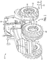
- FIG. 1 is a perspective view of an embodiment of a work vehicle 10 having a suspension system 12.
- the work vehicle 10 and certain components of the work vehicle 10 may be described with reference to a vertical axis or direction 24, a longitudinal axis or direction 26, and a lateral axis or direction 28.
- the work vehicle 10 is a tractor that may be coupled to and configured to tow one or more agricultural implements.
- the work vehicle 10 may be an on-road vehicle, a harvester, a sprayer, or another suitable type of vehicle with a suspension system.
- the work vehicle 10 includes a body 14 configured to house a motor, a transmission, other systems of the work vehicle 10, or a combination thereof. Additionally, the work vehicle 10 includes a cab 16 configured to house an operator. Moreover, the work vehicle 10 includes vehicle wheels, including front wheels 18 and rear wheels 20, at least some of which may be driven by a drive system coupled to the motor and/or the transmission, thereby driving the work vehicle 10 along a field, a road, or any other suitable surface. Each of the front wheels 18 and the rear wheels 20 are coupled to a respective tire 22. The operator may steer the work vehicle 10 by manipulating or providing an input to a hand controller within the cab 16. The hand controller may be a steering wheel.
- the work vehicle 10 may be steered by any suitable controlling device, such as an electronic (e.g., automatic) controlling device located within the work vehicle 10 or remote from the work vehicle 10. Additionally, the operator may slow or stop the work vehicle 10 by manipulating or providing an input to a brake pedal. Furthermore, the work vehicle 10 may be remotely controlled and/or operated autonomously.
- an electronic (e.g., automatic) controlling device located within the work vehicle 10 or remote from the work vehicle 10.
- the operator may slow or stop the work vehicle 10 by manipulating or providing an input to a brake pedal.
- the work vehicle 10 may be remotely controlled and/or operated autonomously.
- the suspension system 12 enables the work vehicle 10 to more efficiently traverse a surface.
- the surface may include various types of terrain.
- the surface may be an uneven surface and/or may include sand, mud, rocks, grass, hills, valleys, other types of terrain, or a combination thereof.
- An axle bar of the suspension system 12 coupled to a respective tire 22 may be configured to pivot generally about the longitudinal axis 26 relative to a frame of the work vehicle 10 to enable the work vehicle 10 to more smoothly and efficiently traverse these various types of terrain.
- the suspension system 12 may increase traction between the surface and the respective tire 22 and may increase occupant comfort in the cab 16.
- FIG. 2 is a perspective view of an embodiment of a suspension system 12 that may be employed in the work vehicle of FIG. 1 .
- the suspension system 12 may be employed in a rear portion of the work vehicle and may be coupled to the rear wheels of the work vehicle.
- the suspension system 12 or portions of the suspension system 12 may be employed in a front portion of the work vehicle and may be coupled to the front wheels of the work vehicle.
- the suspension system 12 may also be coupled to other wheels of the work vehicle.
- the suspension system 12 includes a differential housing 30, an inner housing member 32, a gear housing 34, and a suspension subassembly 40.
- the suspension subassembly 40 includes an axle bar 42, an axle housing 44, a suspension cylinder 46, and a bell crank 48.
- the suspension subassembly 40 includes an outer shaft seal plate 60 and an outer shaft seal 62.
- the suspension system 12 and/or the suspension subassembly 40 may include other and/or additional components.
- the differential housing 30 houses a differential of the suspension system 12.
- the differential may include various gears configured to translate a motion of a drive shaft to the axle bar 42.
- the drive shaft may be disposed along and/or parallel to the longitudinal axis 26 and may be coupled to the differential adjacent to or within the differential housing 30.
- the drive shaft may translate motion and power generated by an engine of the work vehicle to the differential.
- a first end of the drive shaft may be coupled to the engine (e.g., via a transmission), and a second end of the drive shaft may be coupled to gears of the differential.
- the engine may rotate the drive shaft which may rotate the gears of the differential.
- the gears of the differential may be coupled to a gear system.
- a sun shaft of the gear system may be coupled to the gears of the differential and may be driven to rotate as the gears of the differential rotate.
- Rotation of the sun shaft may drive rotation of planetary gears of the gear system.
- Rotation of the planetary gears may drive rotation of a planetary carrier which may rotate the axle bar 42 of the suspension system 12.
- the power generated by the engine may be transferred to the axle bar 42 via the drive shaft, the differential, and the gear system, thereby driving the axle bar 42 to rotate.
- the inner housing member 32 is coupled to the differential housing 30 and the gear housing 34.
- the inner housing member 32 may house portions of the gear system.
- the inner housing member 32 may house portions of the sun shaft and/or other portions of the gear system.
- the gear housing 34 is coupled to the inner housing member 32 and the axle housing 44.
- the gear housing 34 houses a portion of the gear system (e.g., a portion of the sun shaft, the planetary gears, the planetary carrier, and a ring gear).
- the gear housing 34 may house all of the gear system or may include portion(s) of the gear system (e.g., the gear housing may be the ring gear of the gear system).
- one or more seals may be disposed between the differential housing 30 and the inner housing member 32, between the inner housing member 32 and the gear housing 34, between the gear housing 34 and the axle housing 44, or a combination thereof.
- the differential housing 30, the inner housing member 32, the gear housing 34, the axle housing 44, or a combination thereof may be a single component.
- the axle housing 44 is coupled to the gear housing 34 and the outer shaft seal plate 60.
- the axle housing 44 houses an inner control member, a slide housing, and an outer control member.
- the axle housing 44 may house other and/or additional components.
- the suspension subassembly 40 includes the axle housing 44, the inner control member, the slide housing, the outer control member. In certain embodiments, the suspension subassembly 40 may include other and/or additional components.
- the outer shaft seal plate 60 is coupled to the axle housing 44 and the outer shaft seal 62.
- the outer shaft seal plate 60 provides an interface for the outer shaft seal 62 to couple to other components of the suspension system 12 (e.g., to the axle bar 42).
- the outer shaft seal plate 60 may be omitted such that the outer shaft seal 62 couples directly to the axle housing 44 or to the outer control member.
- the axle bar 42 protrudes through the outer shaft seal plate 60 and the outer shaft seal 62. As the axle bar 42 pivots and rotates, the outer shaft seal 62 substantially maintains a seal at an interface of the axle bar 42 and the outer shaft seal plate 60.
- the bell crank 48 is coupled to the axle housing 44 at a pivot point 74 of the bell crank 48, to the suspension cylinder 46 at a first end 70 of the bell crank 48, and to a connecting rod at a second end 72 of the bell crank 48.
- the connecting rod may be coupled to the slide housing at a first end of the connecting rod and to the bell crank 48 at a second end of the connecting rod.
- the bell crank 48 rotates about the pivot point 74.
- the connecting rod moves generally along the vertical axis 24. The movement of the connecting rod causes the bell crank 48 to rotate about the pivot point 74.
- the first end 70 of the bell crank 48 includes multiple connection points 76 each configured to connect the bell crank 48 to the suspension cylinder 46.
- Each connection point 76 may enable the suspension subassembly 40 provide a target damping/firmness for a corresponding wheel position.
- the wheel position is a position of the wheel along the axle bar 42.
- the suspension cylinder 46 may be adjusted to connect to a different connection point 76.
- the different locations of the connection points 76 facilitate control of the force applied by the suspension cylinder 46.
- the different locations of the connection points 76 and the ability to adjust the location where the suspension cylinder 46 is coupled to the bell crank 48 enables the suspension subassembly 40 to provide different levels of suspension damping/firmness.
- the suspension cylinder 46 is coupled to the bell crank 48 at a first end of the suspension cylinder 46 and to a portion of the work vehicle frame at a second end of the suspension cylinder 46.
- the second end of the suspension cylinder 46 may be coupled to the differential housing 30, which is coupled to the work vehicle frame.
- the suspension cylinder 46 compresses or extends depending on the movement of the bell crank 48 and the axle bar 42.
- the suspension cylinder 46 is a hydraulic cylinder configured to selectively compress and extend.
- the suspension cylinder 46 may be a pneumatic cylinder, a spring, or another suspension component configured to absorb energy associated with the axle bar 42 pivoting.
- the axle bar 42 is configured to generally pivot along an upward direction 64 and a downward direction 66 and generally rotate along a rotational direction 68.
- Each of the upward direction 64 and the downward direction 66 are generally along the vertical axis 24, and the rotational direction 68 is generally about the lateral axis 28.
- the slide housing and the connecting rod also move generally downwardly in the downward direction 66.
- the second end 72 of the bell crank 48 is pulled downwardly by the connecting rod.
- the bell crank 48 rotates about the pivot point 74, such that the first end 70 moves away from the suspension cylinder 46.
- the rotation of the bell crank 48 causes the suspension cylinder 46 to extend.
- the extension of the suspension cylinder 46 dissipates a portion of the energy associated with the axle bar 42 pivoting generally downwardly in the downward direction 66.
- the slide housing and the connecting rod also move generally upwardly in the upward direction 64.
- the second end 72 of the bell crank 48 is pushed upwardly by the connecting rod.
- the bell crank 48 rotates about the pivot point 74, such that the first end 70 moves toward the suspension cylinder 46.
- the rotation of the bell crank 48 causes the suspension cylinder 46 to compress.
- the compression of the suspension cylinder 46 dissipates a portion of the energy associated with the axle bar 42 pivoting generally upwardly in the upward direction 64.
- the suspension cylinder 46 extends generally along the lateral axis 28. However, in certain embodiments, the suspension cylinder 46 may extend generally along the vertical axis 24 or in an orientation generally between the vertical axis 24 and the lateral axis 28, and may be configured to absorb energy associated with the pivoting of the axle bar 42.
- FIG. 3 is a cross-sectional view of an embodiment of the suspension system 12 of FIG. 2 , taken along line 3-3 of FIG. 2 .
- the suspension system 12 includes the differential housing 30, the inner housing member 32, the gear housing 34, the gear system 80, and the suspension subassembly 40.
- each of the inner housing member 32, the gear housing 34, the gear system 80, and the suspension subassembly 40 are disposed on a first side and a second side of the differential housing 30.
- the inner housing member 32 houses a portion of the gear system 80, including sun gear 82 and planetary carrier 84.
- the planetary carrier 84 is coupled to the sun gear 82 and to the axle bar 42.
- the gear housing 34 houses a portion of the gear system 80.
- the inner housing member 32, the gear housing 34, the axle housing 44, or a combination thereof may form a single housing configured to house components and systems of the suspensions system 12.
- a differential disposed generally in the differential housing 30 may be configured to rotate the sun gear 82 of the gear system 80 on each side of the suspension system 12.
- the sun gear 82 may drive rotation of the planetary gears and the planetary carrier 84 of the gear system 80.
- the planetary carrier 84 may drive rotation of the axle bar 42.
- the suspension subassembly 40 includes the axle bar 42, an inner shaft seal plate 58, an inner shaft seal 59, an inner control member 50, a slide housing 52, an outer controller member 54, a connecting rod 56, a connecting rod seal 57, the suspension cylinder 46, the bell crank 48, the outer shaft seal plate 60, and the outer shaft seal 62.
- the suspension subassembly 40 may also include the differential housing 30, the inner housing member 32, the gear housing 34, the gear system 80, or a combination thereof.
- the inner control member 50 and the inner shaft seal plate 58 are individual components. Embodiments with the inner control member 50 and the inner shaft seal plate 58 as individual components may facilitate replacing the inner control member 50, the inner shaft seal plate 58, the inner shaft seal 59, other components of the suspension subassembly 40, or a combination thereof. Additionally, shims may be disposed between the inner control member 50 and the inner shaft seal plate 58 to enable an appropriate fit of the components of the suspension subassembly 40. However, in certain embodiments, the inner control member 50 and the inner shaft seal plate 58 may be a single component coupled to the inner shaft seal 59, the slide housing 52, the axle housing, or a combination thereof.
- the suspension subassembly 40 also includes an axle bar cap 85 at the end of each axle bar 42 adjacent to the planetary carrier 84.
- the axle bar cap 85 is configured to form a seal within the planetary carrier 84 inward from the end of the axle bar 42 along the lateral axis 28 as the axle bar 42 pivots and/or rotates.
- the inner shaft seal 59 is coupled to an interior portion of the inner shaft seal plate 58 and is configured to form a seal at the planetary carrier 84.
- the axle bar 42 protrudes through the inner shaft seal plate 58 and into the planetary carrier 84.
- the inner shaft seal 59 is configured to substantially maintain a seal at an interface of the planetary carrier 84 and the inner shaft seal plate 58 as the planetary carrier 84 rotates.
- the axle bar cap 85 and the inner shaft seal 59 in combination, provide a seal and/or fluid barrier between the gear system 80 and the suspension subassembly 40.
- the inner shaft seal plate 58 is rigidly coupled to the axle housing 44 and to the inner control member 50.
- the slide housing 52 is pivotally coupled to the inner control member 50 and to the outer control member 54. As such, the slide housing 52 is configured to pivot with the axle bar 42 and relative to the axle housing 44, the inner shaft seal plate 58, the inner control member 50, and the outer control member 54.
- the axle bar 42 is configured to pivot about a pivot point 27, such that the wheel end 78 moves generally vertically in the upward direction 64 and in the downward direction 66. Additionally, the axle bar 42 is non-rotatably coupled to the gear system 80 and pivotally coupled to the gear system 80. For example, a crowned spline connection may provide the pivotable joint that is a non-rotatably coupling.
- the axle bar 42 is configured to pivot about the pivot point 27 as the gear system 80 drives the axle bar 42 in the rotational direction. As the axle bar 42 pivots about the pivot point 27, one or more portions of the suspension subassembly 40 may pivot with the axle bar 42.
- the slide housing 52 is configured to pivot about the pivot point 27 with the axle bar 42.
- the connecting rod 56 is coupled at a first end to the slide housing 52.
- a second end of the connecting rod 56 is coupled to the second end 72 of the bell crank 48.
- the connecting rod 56 extends through a hole of the axle housing 44.
- the connecting rod seal 57 is coupled to the axle housing 44 and is configured to substantially maintain a seal between the connecting rod 56 and the axle housing 44 at the opening in the axle housing 44 as the connecting rod 56 moves relative the axle housing 44.
- the connecting rod 56 transfers motion of the slide housing 52 to the bell crank 48.
- the transfer of motion from the connecting rod 56 causes the bell crank 48 to rotate about the pivot point 74.
- the bell crank 48 rotates about the pivot point 74 as the slide housing 52 and the axle bar 42 pivot.
- the bell crank 48 is coupled to the suspension cylinder 46 at the first end 70 of the bell crank 48 and to the connecting rod 56 at the second end 72 of the bell crank 48.
- the suspension cylinder 46 is selectively driven to extend and compress.
- a first end of the suspension cylinder 46 is coupled to the first end 70 of the bell crank 48, and a second end of the suspension cylinder 46 is coupled to the frame of the work vehicle.
- the bell crank 48 is driven to rotate, thereby driving the suspension cylinder 46 to extend and compress. In this manner, the suspension cylinder 46 may absorb energy associated with the axle bar 42 pivoting.
- FIG. 4 is a side view of the gear system 80 of the suspension system of FIG. 2 .
- the gear system 80 includes a sun gear 82, a planetary carrier 84, planet gears 86, and a ring gear 88.
- each of the sun gear 82, the planetary carrier 84, the planet gears 86, and the ring gear 88 includes teeth configured to mate to another gear.
- the sun gear 82 is non-rotatably coupled to the differential of the suspension system, and the teeth of the sun gear 82 engaged corresponding teeth of the planet gears 86.
- the planetary carrier 84 is coupled to each planet gear 86 and is configured to rotate as the planet gears 86 rotate.
- the teeth of the planet gears 86 engage corresponding teeth of the ring gear 88.
- the ring gear 88 is coupled to the gear housing 34.
- the sun gear 82 is driven to rotate by the differential of the suspension system.
- the rotation of the sun gear 82 drives rotation of the planet gears 86 around an interior of the ring gear 88.
- the rotation of the planet gears 86 drives the planetary carrier 84 to rotate in the same direction of rotation as the sun gear 82 and at a different rotational speed compared to the sun gear 82.
- the planetary carrier 84 is coupled to a first side of the axle bar and is configured to drive the axle bar to rotate.
- the gear system 80 may translate rotational motion from the differential to the axle bar, thereby enabling the axle to drive the corresponding wheel to rotate.
- the planetary carrier 84 and the driven end of the axle bar are splined to non-rotatably couple the axle bar to the planetary carrier 84.
- the splines of the driven end of the axle bar may be crowned to enable the axle bar to pivot while non-rotatably coupled to the planetary carrier 84.
- the axle bar may be configured to pivot about a pivot point at the driven end of the axle bar while non-rotatably coupled to the planetary carrier 84.
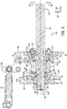
- FIG. 5 is a perspective view of the suspension subassembly 40 of the suspension system of FIG. 2 .
- the suspension subassembly 40 includes the axle bar 42, the inner control member 50, the slide housing 52, and the outer control member 54.
- the suspension subassembly 40 may include additional components of the suspension system described herein.
- the axle bar 42 includes a first end 90 (e.g., the driven end) coupled to the axle bar cap 85 and a second end 94 (e.g., the wheel end).
- the first end 90 extends from a first portion 92 of the axle bar 42 to a second portion 93 of the axle bar 42.
- the first end 90 includes splines 91 and is configured to couple to the gear system.
- the splines 91 may interface with corresponding splines of the planetary carrier of the gear system to enable the gear system to drive the axle bar 42 to rotate.
- the first end 90 is crowned such that a first diameter of the axle bar 42 at the splines 91 is larger than a second diameter of the axle bar 42 at the first portion 92 and at the second portion 93.
- the crown of the first end 90 may enable the axle bar 42 to pivot about a pivot point 27 while being non-rotatably coupled to the gear system. Accordingly, the axle bar 42 may rotate while pivoting about the pivot point 27.
- the second end 94 of the axle bar 42 may be coupled to the wheel.
- a first end 100 of the slide housing 52 has a first sidewall 101, a second sidewall 102, and a third sidewall 103.
- the first sidewall 101 and the second sidewall 102 extend along the vertical axis 24 and are disposed generally opposite each other along the longitudinal axis 26 at the first end 100.
- the third sidewall 103 extends along the longitudinal axis 26 and is generally disposed between the first sidewall 101 and the second sidewall 102.
- the inner control member 50 is disposed between the first sidewall 101 and the second sidewall 102 and is in contact with the slide housing 52 at the first sidewall 101 and the second sidewall 102.
- the slide housing 52 is configured pivot as the axle bar 42 pivots about the pivot point 27.
- the inner control member 50 remains in contact with the first sidewall 101 and the second sidewall 102.
- a lubricant may be disposed between the inner control member 50 and the first sidewall 101 and/or between the inner control member 50 and the second sidewall 102 to facilitate movement of the slide housing 52 along the inner control member 50.
- the contact between the inner control member 50 and the first sidewall 101 and between the inner control member 50 and the second sidewall 102 blocks movement the slide housing 52 relative to the inner control member 50 along the longitudinal axis 26 and blocks rotation of the slide housing 52 as the axle bar 42 rotates.
- the third sidewall 103 is a stop surface configured to stop the pivoting of the slide housing 52 at a top and a bottom of the slide housing 52 and at a corresponding top and a corresponding bottom of the inner control member 50.
- a second end 104 of the slide housing 52 is disposed generally opposite the first end 100 of the slide housing 52 along the lateral axis 28.
- the second end 104 is configured to contact and move along the outer control member 54.
- the outer control member 54 has a first sidewall 105, a second sidewall 106, and a third sidewall 107.
- the first sidewall 105 and the second sidewall 106 extend along the vertical axis 24 and are disposed opposite each other along the longitudinal axis 26.
- the third sidewall 107 extends along the longitudinal axis 26 and is disposed between the first sidewall 105 and the second sidewall 106.
- the second end 104 of the slide housing 52 is disposed between the first sidewall 105 and the second sidewall 106 and is in contact with the outer control member 54 at the first sidewall 105 and the second sidewall 106.
- the slide housing 52 is configured to pivot as the axle bar 42 pivots about the pivot point 27. As the slide housing 52 pivots, the slide housing 52 remains in contact with the first sidewall 105 and the second sidewall 106.
- a lubricant may be disposed between the second end 104 of the slide housing 52 and the first sidewall 105 and/or between the second end 104 of the slide housing 52 and the second sidewall 106 to facilitate movement of the slide housing 52 along the outer control member 54.
- the axle bar 42 and the slide housing 52 are configured to pivot about the pivot point 27 relative to the inner control member 50 and the outer control member 54.
- the inner control member 50 and the outer control member 54 may guide the slide housing 52 as the axle bar 42 and the slide housing 52 pivot about the pivot point 27.
- the first sidewall 101 and the second sidewall 102 of the first end 100 of the slide housing 52 may block motion of the slide housing 52 along the longitudinal axis 26 as the slide housing 52 pivots about the pivot point 27.
- the first sidewall 105 and the second sidewall 106 of the outer control member 54 may block motion of the slide housing 52 along the longitudinal axis 26 as the slide housing 52 pivots about the pivot point 27.
- the sidewalls 101, 102, 105, and 106 prevent rotation of the slide housing 52 about the lateral axis 28 and restrict the slide housing 52 to the pivoting motion generally about the longitudinal axis 26.
- FIG. 6 is a cross-sectional view of the suspension subassembly 40, in which the axle is in the first position.
- the axle bar 42 extends through the inner shaft seal plate 58, the inner control member 50, the slide housing 52, the outer control member 54, the outer shaft seal plate 60, and the outer shaft seal 62.
- the axle bar 42 is configured to pivot about the pivot point 27 and to rotate.
- the inner shaft seal 59, the outer shaft seal 62, and the axle bar cap 85 are configured to substantially maintain a seal at the axle bar 42.
- the slide housing 52 also pivots about the pivot point 27.
- the movement of the slide housing 52 causes the connecting rod 56 to drive the bell crank 48 to rotate. Rotation of the bell crank 48 drives the suspension cylinder 46 to selectively extend and compress.
- bearings are disposed within the slide housing 52 to enable the axle bar 42 to rotate relative to the slide housing 52.
- a first bearing assembly 140 and a second bearing assembly 144 are disposed within the slide housing 52.
- the first bearing assembly 140 includes an inner ring 141, bearings 142, and an outer ring 143.
- the second bearing assembly 144 includes an inner ring 145, bearings 146, and an outer ring 147.
- the inner ring 141 and the inner ring 145 are disposed on the axle bar 42 and configured to rotate with the axle bar 42. As the inner ring 141 and the inner ring 145 rotate, the bearings 142 and the bearings 146 rotate around the outer ring 143 and the outer ring 147, respectively.
- the outer ring 143 and the outer ring 147 are non-rotatably coupled to the slide housing 52 and remain stationary relative to the rotation of the axle bar 42.
- a lubricant may be disposed within each of the first bearing assembly 140 and the second bearing assembly 144 to facilitate rotation of the axle bar 42.
- the inner ring 141, the bearings 142, the inner ring 145, and the bearings 146 may rotate within the slide housing 52, thereby establishing a rotatable coupling between the slide housing 52 and the axle bar 42.
- the inner control member 50, the slide housing 52, and the outer control member 54 include surfaces that enable the slide housing 52 to pivot relative to the inner control member 50 and the outer control member 54.
- the inner control member 50 includes a first surface 120, a second surface 121, and a third surface 122.
- the first surface 120 and the second surface 121 are generally flat, and the third surface 122 is concentric about the pivoting axis of the axle bar 42.
- the third sidewall 103 of the first end 100 of the slide housing 52 includes a first surface 110, a second surface 111, and a third surface 112.
- the first surface 110 and the second surface 111 are generally flat, and the third surface 112 is concentric about the pivoting axis of the axle bar 42.
- the third surface 112 of the slide housing 52 moves along the third surface 122 of the inner control member 50.
- the concentric shapes of the third surface 112 of the slide housing 52 and the third surface 122 of the inner control member 50 enable the slide housing 52 to pivot relative to the inner control member 50 and about the pivot point 27. Further, contact between the third surface 112 of the slide housing 52 and the third surface 122 of the inner control member 50 blocks inward movement of the slide housing 52 along the lateral axis 28 and controls the pivoting of the axle bar 42 along the upward direction 64 and the downward direction 66.
- the first surface 110 of the third sidewall 103 is disposed at a first end of the sidewall 103.
- the first surface 110 is configured to contact the first surface 120 of the inner control member 50 as the wheel end 78 of the axle moves generally upwardly along the vertical axis 24 and in the upward direction 64.
- the first surface 110 of the third sidewall 103 and the first surface 120 of the inner control member 50 block the pivoting movement of the axle bar 42 and the slide housing 52 when the first surface 110 of the third sidewall 103 contacts the first surface 120 of the inner control member 50.
- the second surface 111 of the third sidewall 103 is disposed at a second end of the sidewall 103.
- the second surface 111 is configured to contact the second surface 121 of the inner control member 50 as the wheel end 78 of the axle moves generally downwardly along the vertical axis 24 and in the downward direction 66.
- the second surface 111 of the third sidewall 103 and the second surface 121 of the inner control member 50 block the pivoting movement of the axle bar 42 and the slide housing 52 when the second surface 111 of the third sidewall 103 contacts the second surface 121 of the inner control member 50.
- the third sidewall 107 of the outer control member 54 is configured to contact a sidewall 130 of the second end 104 of the slide housing 52.
- the sidewall 130 is configured to move along the third sidewall 107.
- a lubricant may be disposed between the third sidewall 107 and the sidewall 130 to facilitate movement of the sidewall 130 along the third sidewall 107.
- the suspension subassembly 40 includes an inner bearing seal 148 and an outer bearing seal 149.
- the inner bearing seal 148 forms and substantially maintains a seal between the first bearing assembly 140 and portions of the slide housing 52 and/or other portions of the suspension subassembly 40 (e.g., the inner control member 50, the inner shaft seal 59, etc.).
- the outer bearing seal 149 forms and substantially maintains a seal between the second bearing assembly 144 and portions of the slide housing 52 and/or other portions of the suspension subassembly 40 (e.g., the outer control member 54, the outer shaft seal 62, etc.).
- the inner bearing seal 148 and the outer bearing seal 149 enable the first bearing assembly 140 and the second bearing assembly 144 to be lubricated with oil and/or with other lubricants.
- the area adjacent to the first bearing assembly 140 and the second bearing assembly 144 may be lubricated with a first lubricant (e.g., oil), and the area adjacent to the surfaces of the inner control member 50, the slide housing 52, and the outer control member 54 contacting one another (e.g., the third surface 112, the third surface 122, the third sidewall 107, the sidewall 130, etc.) may be lubricated with a second lubricant (e.g., grease).
- the inner bearing seal 148 and the outer bearing seal 149 may form and substantially maintain the seal such that the first and second lubricants do not mix.
- the axle bar 42 includes an inner chamfer 150 and an outer chamfer 152.
- the inner chamfer 150 extends along the axle bar 42 toward the wheel end 78, the inner chamfer 150 increases in width such that a slope is created along the axle bar 42.
- the inner chamfer 150 at least partially prevents a stress riser along the axle bar 42.
- the outer chamfer 152 is an extension protruding radially from the axle bar 42.
- the protrusion of the outer chamfer 152 is configured to extend into a slot created by a first end component 154 and a second end component 156.
- the outer chamfer 152 is configured to block movement of the axle bar 42 inwardly and/or outwardly along the lateral axis 28.
- the suspension subassembly 40 also includes a ring 158 (e.g., a snap ring and shims) that is disposed around the axle bar 42 adjacent to the first bearing assembly 140 such that the axle bar 42 protrudes through the ring 158.
- the ring 158 blocks movement of the first bearing assembly 140 inwardly along the lateral axis 28 and toward the differential.
- the inner ring 141 may contact the ring 158 to block the inward movement of the axle bar 42.
- FIG. 7 is a cross-sectional view of the suspension subassembly 40 of FIG. 5 , in which the axle bar 42 is in the second position.
- the axle bar 42 and the slide housing 52 are pivoted about the pivot point 27 relative to the inner control member 50 and the outer control member 54, such that the wheel end 78 of the axle bar 42 is positioned upwardly relative to the first position shown in FIG. 6 .
- the first surface 110 of the slide housing 52 is in contact with the first surface 120 of the inner control member 50, thereby blocking the slide housing 52 from further pivoting upwardly.
- the third surface 112 of the slide housing 52 has moved upward along the third surface 122 of the inner control member 50.
- the sidewall 130 of the slide housing 52 has moved upwardly along the third sidewall 107 of the outer control member 54.
- the illustrated pivoting movement of the slide housing 52 drives the connecting rod 56 generally upwardly along the vertical axis 24.
- the upward movement of the connecting rod 56 drives the bell crank 48 to rotate about the pivot point 74, thereby moving the first end 70 toward the suspension cylinder 46.
- the rotation of the bell crank 48 drives the suspension cylinder 46 to compress.
- the suspension cylinder 46 is in a compressed state.
- the suspension cylinder 46 may compress as wheel end 78 of the axle bar 42 moves upwardly along the vertical axis 24 and in the upward direction 64.
- the axle bar 42 and the slide housing 52 may pivot such that the wheel end 78 of the axle bar 42 moves downwardly along the vertical axis 24.
- the second surface 111 of the slide housing 52 may contact the second surface 121 of the inner control member 50, thereby blocking the slide housing 52 from further pivoting downwardly.
- the third surface 112 of the slide housing 52 may move downwardly along the third surface 122 of the inner control member 50, and the sidewall 130 of the slide housing 52 may move downwardly along the third sidewall 107 of the outer control member 54.
- the connecting rod 56 may be driven downwardly.
- the downward movement of the connecting rod 56 may drive the bell crank 48 to rotate about the pivot point 74, thereby moving the first end 70 away from the suspension cylinder 46.
- the rotation of the bell crank 48 drives the suspension cylinder 46 to expand.
- the suspension cylinder 46 may expand as the wheel end 78 of the axle bar 42 moves downwardly along the vertical axis 24 and in the downward direction 66.
- the suspension subassembly 40 is configured to substantially maintain seals throughout the range of motion of the axle bar 42 and the slide housing 52.
- the connecting rod seal 57 may substantially maintain a seal about the connecting rod 56 as the connecting rod 56 moves relative to the axle housing of the suspension subassembly 40.
- the connecting rod seal 57 may remain coupled to the axle housing while the connecting rod 56 moves.
- the inner shaft seal 59 may substantially maintain the seal at the inner shaft seal plate 58 and the planetary carrier as the planetary carrier rotates.
- the axle bar cap 85 may substantially maintain the seal within the planetary carrier and axially inward of the axle bar 42 as the axle bar 42 rotates and pivots.
- the outer shaft seal 62 may substantially maintain the seal at the outer shaft seal plate 60 and about the axle bar 42 as the axle bar 42 rotates and pivots.
- the suspension system described herein enables a work vehicle to efficiently traverse uneven terrain.
- An axle bar and a slide housing of the suspension system may pivot as the work vehicle travels over such terrain.
- a suspension cylinder coupled to the slide housing may selectively extend and compress as the slide housing pivots.
- the suspension cylinder may absorb energy associated with the pivoting motion of the axle bar and may provide increased traction at tire(s) of the work vehicle.
- the suspension system may enable the work vehicle to more smoothly travel across the terrain and may enhance a user's experience while operating the work vehicle.
- the suspension system may increase a comfort level of the user.
- the ability of the suspension system to more efficiently absorb such energy may prevent other portions of the work vehicle from absorbing the forces. As such, a working life of the other portions of the work vehicle may be extended.
Abstract
Description
- The present disclosure relates to a suspension system for a work vehicle.
- Generally, a work vehicle includes a driveline and wheels that enable the work vehicle to travel across terrain and to support a weight of the work vehicle. The driveline generally includes an axle shaft connecting the work vehicle to a wheel. In certain work vehicles, a spacing between wheels is adjustable. The axle shaft is connected to an axle housing that is rigidly connected to a frame of the work vehicle. The axle shaft is configured to rotate to transfer motion of a drivetrain to the wheel, thereby enabling the work vehicle to travel across the terrain. The work vehicle may travel across various types of terrain, such as uneven field surfaces, paved roads, and other types of terrain. As the work vehicle travels across such terrain, the rigidly connected axle housing may transfer forces associated with movement of the wheel to other portions of the work vehicle, including a cab. This may reduce traction at the wheel and may reduce occupant comfort in the cab.
- Certain embodiments commensurate in scope with the disclosed subject matter are summarized below.
- In certain embodiments, a suspension system for a work vehicle includes an axle bar, an inner control member, an outer control member, and a slide housing. The axle bar extends through the inner control member, the outer control member, and the slide housing. The axle bar is non-rotatably coupled to the slide housing and is configured to pivot with the slide housing and relative to the inner control member and the outer control member.
- These and other features, aspects, and advantages of the present disclosure will become better understood when the following detailed description is read with reference to the accompanying drawings in which like characters represent like parts throughout the drawings, wherein:
-
FIG. 1 is a perspective view of an embodiment of a work vehicle having a suspension system; -
FIG. 2 is a perspective view of an embodiment of a suspension system that may be employed in the work vehicle ofFIG. 1 ; -
FIG. 3 is a cross-sectional view of the suspension system ofFIG. 2 , taken along line 3-3 ofFIG. 2 ; -
FIG. 4 is a side view of a gear system of the suspension system ofFIG. 2 ; -
FIG. 5 is a perspective view of a suspension subassembly of the suspension system ofFIG. 2 ; -
FIG. 6 is a cross-sectional view of a first position of the suspension subassembly ofFIG. 5 ; and -
FIG. 7 is a cross-sectional view of a second position of the suspension subassembly ofFIG. 5 . - One or more specific embodiments of the present disclosure will be described below. In an effort to provide a concise description of these embodiments, all features of an actual implementation may not be described in the specification. It should be appreciated that in the development of any such actual implementation, as in any engineering or design project, numerous implementation-specific decisions must be made to achieve the developers' specific goals, such as compliance with system-related and business-related constraints, which may vary from one implementation to another. Moreover, it should be appreciated that such a development effort might be complex and time consuming, but would nevertheless be a routine undertaking of design, fabrication, and manufacture for those of ordinary skill having the benefit of this disclosure.
- When introducing elements of various embodiments of the present disclosure, the articles "a," "an," "the," and "said" are intended to mean that there are one or more of the elements. The terms "comprising," "including," and "having" are intended to be inclusive and mean that there may be additional elements other than the listed elements. Any examples of operating parameters and/or environmental conditions are not exclusive of other parameters/conditions of the disclosed embodiments.
- Certain embodiments of the present disclosure include a suspension system for a work vehicle. Certain work vehicles are configured to travel across various types of terrain, including terrain with uneven surfaces. Accordingly, a suspension system is described herein that enables a work vehicle to more efficiently traverse terrain with uneven surfaces. In certain embodiments, the suspension system includes an axle bar, an inner control member, an outer control member, and a slide housing. The axle bar is coupled to the slide housing, and the axle bar and the slide housing are configured to pivot relative to the inner control member and the outer control member within an axle housing. As such, in certain embodiments, the axle bar of the suspension system for the work vehicle is configured to pivot as the work vehicle travels across uneven terrain. As the axle bar pivots, the suspension system may absorb energy associated with the work vehicle traveling across the uneven terrain, thereby increasing traction of tires of the work vehicle and increasing occupant comfort in the work vehicle.
- With the foregoing in mind, the present embodiments relating to suspension systems may be utilized in any suitable work vehicle. For example,
FIG. 1 is a perspective view of an embodiment of awork vehicle 10 having asuspension system 12. To facilitate discussion, thework vehicle 10 and certain components of thework vehicle 10 may be described with reference to a vertical axis ordirection 24, a longitudinal axis ordirection 26, and a lateral axis ordirection 28. In the illustrated embodiment, thework vehicle 10 is a tractor that may be coupled to and configured to tow one or more agricultural implements. In certain embodiments, thework vehicle 10 may be an on-road vehicle, a harvester, a sprayer, or another suitable type of vehicle with a suspension system. - In the illustrated embodiment, the
work vehicle 10 includes abody 14 configured to house a motor, a transmission, other systems of thework vehicle 10, or a combination thereof. Additionally, thework vehicle 10 includes acab 16 configured to house an operator. Moreover, thework vehicle 10 includes vehicle wheels, includingfront wheels 18 andrear wheels 20, at least some of which may be driven by a drive system coupled to the motor and/or the transmission, thereby driving thework vehicle 10 along a field, a road, or any other suitable surface. Each of thefront wheels 18 and therear wheels 20 are coupled to arespective tire 22. The operator may steer thework vehicle 10 by manipulating or providing an input to a hand controller within thecab 16. The hand controller may be a steering wheel. However, thework vehicle 10 may be steered by any suitable controlling device, such as an electronic (e.g., automatic) controlling device located within thework vehicle 10 or remote from thework vehicle 10. Additionally, the operator may slow or stop thework vehicle 10 by manipulating or providing an input to a brake pedal. Furthermore, thework vehicle 10 may be remotely controlled and/or operated autonomously. - As described herein, the
suspension system 12 enables thework vehicle 10 to more efficiently traverse a surface. The surface may include various types of terrain. For example, the surface may be an uneven surface and/or may include sand, mud, rocks, grass, hills, valleys, other types of terrain, or a combination thereof. An axle bar of thesuspension system 12 coupled to arespective tire 22 may be configured to pivot generally about thelongitudinal axis 26 relative to a frame of thework vehicle 10 to enable thework vehicle 10 to more smoothly and efficiently traverse these various types of terrain. As such, thesuspension system 12 may increase traction between the surface and therespective tire 22 and may increase occupant comfort in thecab 16. -
FIG. 2 is a perspective view of an embodiment of asuspension system 12 that may be employed in the work vehicle ofFIG. 1 . Thesuspension system 12 may be employed in a rear portion of the work vehicle and may be coupled to the rear wheels of the work vehicle. In certain embodiments, thesuspension system 12 or portions of thesuspension system 12 may be employed in a front portion of the work vehicle and may be coupled to the front wheels of the work vehicle. Thesuspension system 12 may also be coupled to other wheels of the work vehicle. - In the illustrated embodiment, the
suspension system 12 includes adifferential housing 30, aninner housing member 32, agear housing 34, and a suspension subassembly 40. Thesuspension subassembly 40 includes anaxle bar 42, anaxle housing 44, asuspension cylinder 46, and abell crank 48. In the illustrated embodiment, thesuspension subassembly 40 includes an outershaft seal plate 60 and anouter shaft seal 62. In certain embodiments, thesuspension system 12 and/or thesuspension subassembly 40 may include other and/or additional components. - The
differential housing 30 houses a differential of thesuspension system 12. The differential may include various gears configured to translate a motion of a drive shaft to theaxle bar 42. For example, in certain embodiments, the drive shaft may be disposed along and/or parallel to thelongitudinal axis 26 and may be coupled to the differential adjacent to or within thedifferential housing 30. The drive shaft may translate motion and power generated by an engine of the work vehicle to the differential. For example, a first end of the drive shaft may be coupled to the engine (e.g., via a transmission), and a second end of the drive shaft may be coupled to gears of the differential. The engine may rotate the drive shaft which may rotate the gears of the differential. - In certain embodiments, the gears of the differential may be coupled to a gear system. For example, a sun shaft of the gear system may be coupled to the gears of the differential and may be driven to rotate as the gears of the differential rotate. Rotation of the sun shaft may drive rotation of planetary gears of the gear system. Rotation of the planetary gears may drive rotation of a planetary carrier which may rotate the
axle bar 42 of thesuspension system 12. As such, the power generated by the engine may be transferred to theaxle bar 42 via the drive shaft, the differential, and the gear system, thereby driving theaxle bar 42 to rotate. - As illustrated, the
inner housing member 32 is coupled to thedifferential housing 30 and thegear housing 34. Theinner housing member 32 may house portions of the gear system. For example, theinner housing member 32 may house portions of the sun shaft and/or other portions of the gear system. - As illustrated, the
gear housing 34 is coupled to theinner housing member 32 and theaxle housing 44. Thegear housing 34 houses a portion of the gear system (e.g., a portion of the sun shaft, the planetary gears, the planetary carrier, and a ring gear). In certain embodiments, thegear housing 34 may house all of the gear system or may include portion(s) of the gear system (e.g., the gear housing may be the ring gear of the gear system). Further, one or more seals may be disposed between thedifferential housing 30 and theinner housing member 32, between theinner housing member 32 and thegear housing 34, between thegear housing 34 and theaxle housing 44, or a combination thereof. Additionally, in some embodiments, thedifferential housing 30, theinner housing member 32, thegear housing 34, theaxle housing 44, or a combination thereof, may be a single component. - As illustrated, the
axle housing 44 is coupled to thegear housing 34 and the outershaft seal plate 60. Theaxle housing 44 houses an inner control member, a slide housing, and an outer control member. In certain embodiments, theaxle housing 44 may house other and/or additional components. Thesuspension subassembly 40 includes theaxle housing 44, the inner control member, the slide housing, the outer control member. In certain embodiments, thesuspension subassembly 40 may include other and/or additional components. - As illustrated, the outer
shaft seal plate 60 is coupled to theaxle housing 44 and theouter shaft seal 62. The outershaft seal plate 60 provides an interface for theouter shaft seal 62 to couple to other components of the suspension system 12 (e.g., to the axle bar 42). In certain embodiments, the outershaft seal plate 60 may be omitted such that theouter shaft seal 62 couples directly to theaxle housing 44 or to the outer control member. Theaxle bar 42 protrudes through the outershaft seal plate 60 and theouter shaft seal 62. As theaxle bar 42 pivots and rotates, theouter shaft seal 62 substantially maintains a seal at an interface of theaxle bar 42 and the outershaft seal plate 60. - As illustrated, the bell crank 48 is coupled to the
axle housing 44 at apivot point 74 of the bell crank 48, to thesuspension cylinder 46 at afirst end 70 of the bell crank 48, and to a connecting rod at asecond end 72 of thebell crank 48. The connecting rod may be coupled to the slide housing at a first end of the connecting rod and to the bell crank 48 at a second end of the connecting rod. In certain embodiments, the bell crank 48 rotates about thepivot point 74. For example, as theaxle bar 42 pivots, the slide housing moves and pivots within theaxle housing 44. As the slide housing moves and pivots, the connecting rod moves generally along thevertical axis 24. The movement of the connecting rod causes the bell crank 48 to rotate about thepivot point 74. - As illustrated, the
first end 70 of the bell crank 48 includes multiple connection points 76 each configured to connect the bell crank 48 to thesuspension cylinder 46. Eachconnection point 76 may enable thesuspension subassembly 40 provide a target damping/firmness for a corresponding wheel position. The wheel position is a position of the wheel along theaxle bar 42. For example, if a wheel position is changed on the work vehicle, thesuspension cylinder 46 may be adjusted to connect to adifferent connection point 76. The different locations of the connection points 76 facilitate control of the force applied by thesuspension cylinder 46. As such, the different locations of the connection points 76 and the ability to adjust the location where thesuspension cylinder 46 is coupled to the bell crank 48 enables thesuspension subassembly 40 to provide different levels of suspension damping/firmness. - The
suspension cylinder 46 is coupled to the bell crank 48 at a first end of thesuspension cylinder 46 and to a portion of the work vehicle frame at a second end of thesuspension cylinder 46. In certain embodiments, the second end of thesuspension cylinder 46 may be coupled to thedifferential housing 30, which is coupled to the work vehicle frame. As the bell crank 48 rotates about thepivot point 74, thesuspension cylinder 46 compresses or extends depending on the movement of the bell crank 48 and theaxle bar 42. As illustrated, thesuspension cylinder 46 is a hydraulic cylinder configured to selectively compress and extend. In certain embodiments, thesuspension cylinder 46 may be a pneumatic cylinder, a spring, or another suspension component configured to absorb energy associated with theaxle bar 42 pivoting. - As illustrated, the
axle bar 42 is configured to generally pivot along anupward direction 64 and adownward direction 66 and generally rotate along arotational direction 68. Each of theupward direction 64 and thedownward direction 66 are generally along thevertical axis 24, and therotational direction 68 is generally about thelateral axis 28. As awheel end 78 of theaxle bar 42 pivots generally downwardly in the downward direction 66 (e.g., away from the suspension cylinder 46), the slide housing and the connecting rod also move generally downwardly in thedownward direction 66. Thesecond end 72 of the bell crank 48 is pulled downwardly by the connecting rod. As such, the bell crank 48 rotates about thepivot point 74, such that thefirst end 70 moves away from thesuspension cylinder 46. The rotation of the bell crank 48 causes thesuspension cylinder 46 to extend. The extension of thesuspension cylinder 46 dissipates a portion of the energy associated with theaxle bar 42 pivoting generally downwardly in thedownward direction 66. - In another example, as the
wheel end 78 of theaxle bar 42 pivots about thelongitudinal axis 26 and generally upwardly in the upward direction 64 (e.g., toward the suspension cylinder 46), the slide housing and the connecting rod also move generally upwardly in theupward direction 64. Thesecond end 72 of the bell crank 48 is pushed upwardly by the connecting rod. As such, the bell crank 48 rotates about thepivot point 74, such that thefirst end 70 moves toward thesuspension cylinder 46. The rotation of the bell crank 48 causes thesuspension cylinder 46 to compress. The compression of thesuspension cylinder 46 dissipates a portion of the energy associated with theaxle bar 42 pivoting generally upwardly in theupward direction 64. - As illustrated, the
suspension cylinder 46 extends generally along thelateral axis 28. However, in certain embodiments, thesuspension cylinder 46 may extend generally along thevertical axis 24 or in an orientation generally between thevertical axis 24 and thelateral axis 28, and may be configured to absorb energy associated with the pivoting of theaxle bar 42. -
FIG. 3 is a cross-sectional view of an embodiment of thesuspension system 12 ofFIG. 2 , taken along line 3-3 ofFIG. 2 . As illustrated, thesuspension system 12 includes thedifferential housing 30, theinner housing member 32, thegear housing 34, thegear system 80, and thesuspension subassembly 40. In the illustrated embodiment, each of theinner housing member 32, thegear housing 34, thegear system 80, and thesuspension subassembly 40 are disposed on a first side and a second side of thedifferential housing 30. Theinner housing member 32 houses a portion of thegear system 80, includingsun gear 82 andplanetary carrier 84. As illustrated, theplanetary carrier 84 is coupled to thesun gear 82 and to theaxle bar 42. Thegear housing 34 houses a portion of thegear system 80. In certain embodiments, theinner housing member 32, thegear housing 34, theaxle housing 44, or a combination thereof, may form a single housing configured to house components and systems of thesuspensions system 12. A differential disposed generally in thedifferential housing 30 may be configured to rotate thesun gear 82 of thegear system 80 on each side of thesuspension system 12. Thesun gear 82 may drive rotation of the planetary gears and theplanetary carrier 84 of thegear system 80. Theplanetary carrier 84 may drive rotation of theaxle bar 42. - The
suspension subassembly 40 includes theaxle bar 42, an innershaft seal plate 58, aninner shaft seal 59, aninner control member 50, aslide housing 52, anouter controller member 54, a connectingrod 56, a connectingrod seal 57, thesuspension cylinder 46, the bell crank 48, the outershaft seal plate 60, and theouter shaft seal 62. In certain embodiments, thesuspension subassembly 40 may also include thedifferential housing 30, theinner housing member 32, thegear housing 34, thegear system 80, or a combination thereof. - As illustrated, the
inner control member 50 and the innershaft seal plate 58 are individual components. Embodiments with theinner control member 50 and the innershaft seal plate 58 as individual components may facilitate replacing theinner control member 50, the innershaft seal plate 58, theinner shaft seal 59, other components of thesuspension subassembly 40, or a combination thereof. Additionally, shims may be disposed between theinner control member 50 and the innershaft seal plate 58 to enable an appropriate fit of the components of thesuspension subassembly 40. However, in certain embodiments, theinner control member 50 and the innershaft seal plate 58 may be a single component coupled to theinner shaft seal 59, theslide housing 52, the axle housing, or a combination thereof. - As illustrated, the
suspension subassembly 40 also includes anaxle bar cap 85 at the end of eachaxle bar 42 adjacent to theplanetary carrier 84. Theaxle bar cap 85 is configured to form a seal within theplanetary carrier 84 inward from the end of theaxle bar 42 along thelateral axis 28 as theaxle bar 42 pivots and/or rotates. Additionally, theinner shaft seal 59 is coupled to an interior portion of the innershaft seal plate 58 and is configured to form a seal at theplanetary carrier 84. For example, theaxle bar 42 protrudes through the innershaft seal plate 58 and into theplanetary carrier 84. Theinner shaft seal 59 is configured to substantially maintain a seal at an interface of theplanetary carrier 84 and the innershaft seal plate 58 as theplanetary carrier 84 rotates. As such, theaxle bar cap 85 and theinner shaft seal 59, in combination, provide a seal and/or fluid barrier between thegear system 80 and thesuspension subassembly 40. As illustrated, the innershaft seal plate 58 is rigidly coupled to theaxle housing 44 and to theinner control member 50. Theslide housing 52 is pivotally coupled to theinner control member 50 and to theouter control member 54. As such, theslide housing 52 is configured to pivot with theaxle bar 42 and relative to theaxle housing 44, the innershaft seal plate 58, theinner control member 50, and theouter control member 54. - The
axle bar 42 is configured to pivot about apivot point 27, such that thewheel end 78 moves generally vertically in theupward direction 64 and in thedownward direction 66. Additionally, theaxle bar 42 is non-rotatably coupled to thegear system 80 and pivotally coupled to thegear system 80. For example, a crowned spline connection may provide the pivotable joint that is a non-rotatably coupling. For example, theaxle bar 42 is configured to pivot about thepivot point 27 as thegear system 80 drives theaxle bar 42 in the rotational direction. As theaxle bar 42 pivots about thepivot point 27, one or more portions of thesuspension subassembly 40 may pivot with theaxle bar 42. For example, theslide housing 52 is configured to pivot about thepivot point 27 with theaxle bar 42. - The connecting
rod 56 is coupled at a first end to theslide housing 52. A second end of the connectingrod 56 is coupled to thesecond end 72 of thebell crank 48. The connectingrod 56 extends through a hole of theaxle housing 44. The connectingrod seal 57 is coupled to theaxle housing 44 and is configured to substantially maintain a seal between the connectingrod 56 and theaxle housing 44 at the opening in theaxle housing 44 as the connectingrod 56 moves relative theaxle housing 44. As theslide housing 52 pivots about thepivot point 27, the connectingrod 56 transfers motion of theslide housing 52 to thebell crank 48. The transfer of motion from the connectingrod 56 causes the bell crank 48 to rotate about thepivot point 74. As such, the bell crank 48 rotates about thepivot point 74 as theslide housing 52 and theaxle bar 42 pivot. Thebell crank 48 is coupled to thesuspension cylinder 46 at thefirst end 70 of the bell crank 48 and to the connectingrod 56 at thesecond end 72 of thebell crank 48. As the bell crank 48 rotates about thepivot point 74, thesuspension cylinder 46 is selectively driven to extend and compress. A first end of thesuspension cylinder 46 is coupled to thefirst end 70 of the bell crank 48, and a second end of thesuspension cylinder 46 is coupled to the frame of the work vehicle. As such, as theaxle bar 42 and theslide housing 52 pivot, the bell crank 48 is driven to rotate, thereby driving thesuspension cylinder 46 to extend and compress. In this manner, thesuspension cylinder 46 may absorb energy associated with theaxle bar 42 pivoting. -
FIG. 4 is a side view of thegear system 80 of the suspension system ofFIG. 2 . Thegear system 80 includes asun gear 82, aplanetary carrier 84, planet gears 86, and aring gear 88. As illustrated, each of thesun gear 82, theplanetary carrier 84, the planet gears 86, and thering gear 88 includes teeth configured to mate to another gear. Thesun gear 82 is non-rotatably coupled to the differential of the suspension system, and the teeth of thesun gear 82 engaged corresponding teeth of the planet gears 86. Theplanetary carrier 84 is coupled to eachplanet gear 86 and is configured to rotate as the planet gears 86 rotate. The teeth of the planet gears 86 engage corresponding teeth of thering gear 88. Thering gear 88 is coupled to thegear housing 34. Thesun gear 82 is driven to rotate by the differential of the suspension system. The rotation of thesun gear 82 drives rotation of the planet gears 86 around an interior of thering gear 88. The rotation of the planet gears 86 drives theplanetary carrier 84 to rotate in the same direction of rotation as thesun gear 82 and at a different rotational speed compared to thesun gear 82. - The
planetary carrier 84 is coupled to a first side of the axle bar and is configured to drive the axle bar to rotate. As such, thegear system 80 may translate rotational motion from the differential to the axle bar, thereby enabling the axle to drive the corresponding wheel to rotate. In certain embodiments, theplanetary carrier 84 and the driven end of the axle bar are splined to non-rotatably couple the axle bar to theplanetary carrier 84. The splines of the driven end of the axle bar may be crowned to enable the axle bar to pivot while non-rotatably coupled to theplanetary carrier 84. For example, the axle bar may be configured to pivot about a pivot point at the driven end of the axle bar while non-rotatably coupled to theplanetary carrier 84. -
FIG. 5 is a perspective view of thesuspension subassembly 40 of the suspension system ofFIG. 2 . Thesuspension subassembly 40 includes theaxle bar 42, theinner control member 50, theslide housing 52, and theouter control member 54. In certain embodiments, thesuspension subassembly 40 may include additional components of the suspension system described herein. - As illustrated, the
axle bar 42 includes a first end 90 (e.g., the driven end) coupled to theaxle bar cap 85 and a second end 94 (e.g., the wheel end). Thefirst end 90 extends from afirst portion 92 of theaxle bar 42 to asecond portion 93 of theaxle bar 42. Thefirst end 90 includessplines 91 and is configured to couple to the gear system. Thesplines 91 may interface with corresponding splines of the planetary carrier of the gear system to enable the gear system to drive theaxle bar 42 to rotate. In the illustrated embodiment, thefirst end 90 is crowned such that a first diameter of theaxle bar 42 at thesplines 91 is larger than a second diameter of theaxle bar 42 at thefirst portion 92 and at thesecond portion 93. The crown of thefirst end 90 may enable theaxle bar 42 to pivot about apivot point 27 while being non-rotatably coupled to the gear system. Accordingly, theaxle bar 42 may rotate while pivoting about thepivot point 27. Thesecond end 94 of theaxle bar 42 may be coupled to the wheel. - As illustrated, a
first end 100 of theslide housing 52 has afirst sidewall 101, asecond sidewall 102, and athird sidewall 103. Thefirst sidewall 101 and thesecond sidewall 102 extend along thevertical axis 24 and are disposed generally opposite each other along thelongitudinal axis 26 at thefirst end 100. Thethird sidewall 103 extends along thelongitudinal axis 26 and is generally disposed between thefirst sidewall 101 and thesecond sidewall 102. Theinner control member 50 is disposed between thefirst sidewall 101 and thesecond sidewall 102 and is in contact with theslide housing 52 at thefirst sidewall 101 and thesecond sidewall 102. Theslide housing 52 is configured pivot as theaxle bar 42 pivots about thepivot point 27. As theslide housing 52 pivots, theinner control member 50 remains in contact with thefirst sidewall 101 and thesecond sidewall 102. For example, a lubricant may be disposed between theinner control member 50 and thefirst sidewall 101 and/or between theinner control member 50 and thesecond sidewall 102 to facilitate movement of theslide housing 52 along theinner control member 50. Additionally, the contact between theinner control member 50 and thefirst sidewall 101 and between theinner control member 50 and thesecond sidewall 102 blocks movement theslide housing 52 relative to theinner control member 50 along thelongitudinal axis 26 and blocks rotation of theslide housing 52 as theaxle bar 42 rotates. Further, thethird sidewall 103 is a stop surface configured to stop the pivoting of theslide housing 52 at a top and a bottom of theslide housing 52 and at a corresponding top and a corresponding bottom of theinner control member 50. - A
second end 104 of theslide housing 52 is disposed generally opposite thefirst end 100 of theslide housing 52 along thelateral axis 28. Thesecond end 104 is configured to contact and move along theouter control member 54. Theouter control member 54 has afirst sidewall 105, asecond sidewall 106, and athird sidewall 107. Thefirst sidewall 105 and thesecond sidewall 106 extend along thevertical axis 24 and are disposed opposite each other along thelongitudinal axis 26. Thethird sidewall 107 extends along thelongitudinal axis 26 and is disposed between thefirst sidewall 105 and thesecond sidewall 106. Thesecond end 104 of theslide housing 52 is disposed between thefirst sidewall 105 and thesecond sidewall 106 and is in contact with theouter control member 54 at thefirst sidewall 105 and thesecond sidewall 106. Theslide housing 52 is configured to pivot as theaxle bar 42 pivots about thepivot point 27. As theslide housing 52 pivots, theslide housing 52 remains in contact with thefirst sidewall 105 and thesecond sidewall 106. For example, a lubricant may be disposed between thesecond end 104 of theslide housing 52 and thefirst sidewall 105 and/or between thesecond end 104 of theslide housing 52 and thesecond sidewall 106 to facilitate movement of theslide housing 52 along theouter control member 54. - As such, the
axle bar 42 and theslide housing 52 are configured to pivot about thepivot point 27 relative to theinner control member 50 and theouter control member 54. Theinner control member 50 and theouter control member 54 may guide theslide housing 52 as theaxle bar 42 and theslide housing 52 pivot about thepivot point 27. For example, thefirst sidewall 101 and thesecond sidewall 102 of thefirst end 100 of theslide housing 52 may block motion of theslide housing 52 along thelongitudinal axis 26 as theslide housing 52 pivots about thepivot point 27. Thefirst sidewall 105 and thesecond sidewall 106 of theouter control member 54 may block motion of theslide housing 52 along thelongitudinal axis 26 as theslide housing 52 pivots about thepivot point 27. Additionally, thesidewalls slide housing 52 about thelateral axis 28 and restrict theslide housing 52 to the pivoting motion generally about thelongitudinal axis 26. -
FIG. 6 is a cross-sectional view of thesuspension subassembly 40, in which the axle is in the first position. As illustrated, theaxle bar 42 extends through the innershaft seal plate 58, theinner control member 50, theslide housing 52, theouter control member 54, the outershaft seal plate 60, and theouter shaft seal 62. Theaxle bar 42 is configured to pivot about thepivot point 27 and to rotate. As theaxle bar 42 pivots and rotates, theinner shaft seal 59, theouter shaft seal 62, and theaxle bar cap 85 are configured to substantially maintain a seal at theaxle bar 42. As theaxle bar 42 pivots about thepivot point 27, theslide housing 52 also pivots about thepivot point 27. The movement of theslide housing 52 causes the connectingrod 56 to drive the bell crank 48 to rotate. Rotation of the bell crank 48 drives thesuspension cylinder 46 to selectively extend and compress. - In the illustrated embodiment, bearings are disposed within the
slide housing 52 to enable theaxle bar 42 to rotate relative to theslide housing 52. For example, as illustrated, afirst bearing assembly 140 and asecond bearing assembly 144 are disposed within theslide housing 52. Thefirst bearing assembly 140 includes aninner ring 141,bearings 142, and an outer ring 143. Thesecond bearing assembly 144 includes aninner ring 145,bearings 146, and anouter ring 147. Theinner ring 141 and theinner ring 145 are disposed on theaxle bar 42 and configured to rotate with theaxle bar 42. As theinner ring 141 and theinner ring 145 rotate, thebearings 142 and thebearings 146 rotate around the outer ring 143 and theouter ring 147, respectively. The outer ring 143 and theouter ring 147 are non-rotatably coupled to theslide housing 52 and remain stationary relative to the rotation of theaxle bar 42. In certain embodiments, a lubricant may be disposed within each of thefirst bearing assembly 140 and thesecond bearing assembly 144 to facilitate rotation of theaxle bar 42. As such, as theaxle bar 42 rotates, theinner ring 141, thebearings 142, theinner ring 145, and thebearings 146 may rotate within theslide housing 52, thereby establishing a rotatable coupling between theslide housing 52 and theaxle bar 42. - The
inner control member 50, theslide housing 52, and theouter control member 54 include surfaces that enable theslide housing 52 to pivot relative to theinner control member 50 and theouter control member 54. As illustrated, theinner control member 50 includes afirst surface 120, asecond surface 121, and athird surface 122. Thefirst surface 120 and thesecond surface 121 are generally flat, and thethird surface 122 is concentric about the pivoting axis of theaxle bar 42. Thethird sidewall 103 of thefirst end 100 of theslide housing 52 includes afirst surface 110, asecond surface 111, and athird surface 112. Thefirst surface 110 and thesecond surface 111 are generally flat, and thethird surface 112 is concentric about the pivoting axis of theaxle bar 42. As theaxle bar 42 and theslide housing 52 pivot about thepivot point 27, thethird surface 112 of theslide housing 52 moves along thethird surface 122 of theinner control member 50. The concentric shapes of thethird surface 112 of theslide housing 52 and thethird surface 122 of theinner control member 50 enable theslide housing 52 to pivot relative to theinner control member 50 and about thepivot point 27. Further, contact between thethird surface 112 of theslide housing 52 and thethird surface 122 of theinner control member 50 blocks inward movement of theslide housing 52 along thelateral axis 28 and controls the pivoting of theaxle bar 42 along theupward direction 64 and thedownward direction 66. - The
first surface 110 of thethird sidewall 103 is disposed at a first end of thesidewall 103. Thefirst surface 110 is configured to contact thefirst surface 120 of theinner control member 50 as thewheel end 78 of the axle moves generally upwardly along thevertical axis 24 and in theupward direction 64. As such, thefirst surface 110 of thethird sidewall 103 and thefirst surface 120 of theinner control member 50 block the pivoting movement of theaxle bar 42 and theslide housing 52 when thefirst surface 110 of thethird sidewall 103 contacts thefirst surface 120 of theinner control member 50. - The
second surface 111 of thethird sidewall 103 is disposed at a second end of thesidewall 103. Thesecond surface 111 is configured to contact thesecond surface 121 of theinner control member 50 as thewheel end 78 of the axle moves generally downwardly along thevertical axis 24 and in thedownward direction 66. As such, thesecond surface 111 of thethird sidewall 103 and thesecond surface 121 of theinner control member 50 block the pivoting movement of theaxle bar 42 and theslide housing 52 when thesecond surface 111 of thethird sidewall 103 contacts thesecond surface 121 of theinner control member 50. - The
third sidewall 107 of theouter control member 54 is configured to contact asidewall 130 of thesecond end 104 of theslide housing 52. Thesidewall 130 is configured to move along thethird sidewall 107. For example, as theslide housing 52 pivots about thepivot point 27, thesidewall 130 may move along thethird sidewall 107. A lubricant may be disposed between thethird sidewall 107 and thesidewall 130 to facilitate movement of thesidewall 130 along thethird sidewall 107. - As illustrated, the
suspension subassembly 40 includes aninner bearing seal 148 and anouter bearing seal 149. Theinner bearing seal 148 forms and substantially maintains a seal between thefirst bearing assembly 140 and portions of theslide housing 52 and/or other portions of the suspension subassembly 40 (e.g., theinner control member 50, theinner shaft seal 59, etc.). Theouter bearing seal 149 forms and substantially maintains a seal between thesecond bearing assembly 144 and portions of theslide housing 52 and/or other portions of the suspension subassembly 40 (e.g., theouter control member 54, theouter shaft seal 62, etc.). As such, theinner bearing seal 148 and theouter bearing seal 149 enable thefirst bearing assembly 140 and thesecond bearing assembly 144 to be lubricated with oil and/or with other lubricants. For example, the area adjacent to thefirst bearing assembly 140 and thesecond bearing assembly 144 may be lubricated with a first lubricant (e.g., oil), and the area adjacent to the surfaces of theinner control member 50, theslide housing 52, and theouter control member 54 contacting one another (e.g., thethird surface 112, thethird surface 122, thethird sidewall 107, thesidewall 130, etc.) may be lubricated with a second lubricant (e.g., grease). Theinner bearing seal 148 and theouter bearing seal 149 may form and substantially maintain the seal such that the first and second lubricants do not mix. - As illustrated, the
axle bar 42 includes aninner chamfer 150 and an outer chamfer 152. As theinner chamfer 150 extends along theaxle bar 42 toward thewheel end 78, theinner chamfer 150 increases in width such that a slope is created along theaxle bar 42. Theinner chamfer 150 at least partially prevents a stress riser along theaxle bar 42. As illustrated, the outer chamfer 152 is an extension protruding radially from theaxle bar 42. The protrusion of the outer chamfer 152 is configured to extend into a slot created by a first end component 154 and asecond end component 156. As such, the outer chamfer 152 is configured to block movement of theaxle bar 42 inwardly and/or outwardly along thelateral axis 28. - As illustrated, the
suspension subassembly 40 also includes a ring 158 (e.g., a snap ring and shims) that is disposed around theaxle bar 42 adjacent to thefirst bearing assembly 140 such that theaxle bar 42 protrudes through thering 158. Thering 158 blocks movement of thefirst bearing assembly 140 inwardly along thelateral axis 28 and toward the differential. For example, theinner ring 141 may contact thering 158 to block the inward movement of theaxle bar 42. -
FIG. 7 is a cross-sectional view of thesuspension subassembly 40 ofFIG. 5 , in which theaxle bar 42 is in the second position. As illustrated, theaxle bar 42 and theslide housing 52 are pivoted about thepivot point 27 relative to theinner control member 50 and theouter control member 54, such that thewheel end 78 of theaxle bar 42 is positioned upwardly relative to the first position shown inFIG. 6 . Thefirst surface 110 of theslide housing 52 is in contact with thefirst surface 120 of theinner control member 50, thereby blocking theslide housing 52 from further pivoting upwardly. Thethird surface 112 of theslide housing 52 has moved upward along thethird surface 122 of theinner control member 50. Thesidewall 130 of theslide housing 52 has moved upwardly along thethird sidewall 107 of theouter control member 54. - The illustrated pivoting movement of the
slide housing 52 drives the connectingrod 56 generally upwardly along thevertical axis 24. As illustrated, the upward movement of the connectingrod 56 drives the bell crank 48 to rotate about thepivot point 74, thereby moving thefirst end 70 toward thesuspension cylinder 46. The rotation of the bell crank 48 drives thesuspension cylinder 46 to compress. As illustrated, thesuspension cylinder 46 is in a compressed state. As such, thesuspension cylinder 46 may compress aswheel end 78 of theaxle bar 42 moves upwardly along thevertical axis 24 and in theupward direction 64. - In certain embodiments, the
axle bar 42 and theslide housing 52 may pivot such that thewheel end 78 of theaxle bar 42 moves downwardly along thevertical axis 24. As theslide housing 52 is pivoted generally downward about thepivot point 27, thesecond surface 111 of theslide housing 52 may contact thesecond surface 121 of theinner control member 50, thereby blocking theslide housing 52 from further pivoting downwardly. Additionally, as theslide housing 52 is pivoted generally downwardly about thepivot point 27, thethird surface 112 of theslide housing 52 may move downwardly along thethird surface 122 of theinner control member 50, and thesidewall 130 of theslide housing 52 may move downwardly along thethird sidewall 107 of theouter control member 54. - As the
axle bar 42 and theslide housing 52 pivot generally downwardly away from thesuspension cylinder 46, the connectingrod 56 may be driven downwardly. The downward movement of the connectingrod 56 may drive the bell crank 48 to rotate about thepivot point 74, thereby moving thefirst end 70 away from thesuspension cylinder 46. The rotation of the bell crank 48 drives thesuspension cylinder 46 to expand. As such, thesuspension cylinder 46 may expand as thewheel end 78 of theaxle bar 42 moves downwardly along thevertical axis 24 and in thedownward direction 66. - The
suspension subassembly 40 is configured to substantially maintain seals throughout the range of motion of theaxle bar 42 and theslide housing 52. For example, the connectingrod seal 57 may substantially maintain a seal about the connectingrod 56 as the connectingrod 56 moves relative to the axle housing of thesuspension subassembly 40. The connectingrod seal 57 may remain coupled to the axle housing while the connectingrod 56 moves. Additionally, theinner shaft seal 59 may substantially maintain the seal at the innershaft seal plate 58 and the planetary carrier as the planetary carrier rotates. Theaxle bar cap 85 may substantially maintain the seal within the planetary carrier and axially inward of theaxle bar 42 as theaxle bar 42 rotates and pivots. Further, theouter shaft seal 62 may substantially maintain the seal at the outershaft seal plate 60 and about theaxle bar 42 as theaxle bar 42 rotates and pivots. - The suspension system described herein enables a work vehicle to efficiently traverse uneven terrain. An axle bar and a slide housing of the suspension system may pivot as the work vehicle travels over such terrain. A suspension cylinder coupled to the slide housing may selectively extend and compress as the slide housing pivots. The suspension cylinder may absorb energy associated with the pivoting motion of the axle bar and may provide increased traction at tire(s) of the work vehicle. In this manner, the suspension system may enable the work vehicle to more smoothly travel across the terrain and may enhance a user's experience while operating the work vehicle. For example, the suspension system may increase a comfort level of the user. Additionally, the ability of the suspension system to more efficiently absorb such energy may prevent other portions of the work vehicle from absorbing the forces. As such, a working life of the other portions of the work vehicle may be extended.
Claims (15)
- A suspension system (12) for a work vehicle (10), characterized in that the suspension system (12) comprises:an axle bar (42);an inner control member (50);an outer control member (54); anda slide housing (52), wherein the axle bar (42) extends through the inner control member (50), the outer control member (54), and the slide housing (52), and the axle bar (42) is non-rotatably coupled to the slide housing (52) and is configured to pivot with the slide housing (52) and relative to the inner control member (50) and the outer control member (54).
- The suspension system (12) of claim 1, wherein the inner control member (50) and the outer control member (54) are configured to be rigidly coupled to an axle housing (44).
- The suspension system (12) of any of claims 1 or 2, wherein the axle bar (42) is configured to couple to a gear system (80) at a first end (90) of the axle bar (42) and to couple to a wheel (18, 20) at a second end (94) of the axle bar (42).
- The suspension system (12) of any of claims 1-3, comprising a suspension cylinder (46) coupled to the slide housing (52).
- The suspension system (12) of claim 4, wherein the suspension cylinder (46) is configured to absorb energy associated with the pivoting of the slide housing (52).
- The suspension system (12) of any of claims 4 or 5, comprising a bell crank (48) and a connecting rod (56), wherein the bell crank (48) is configured to couple to the suspension cylinder (46) and to the connecting rod (56), and the connecting rod (56) is configured to couple to the bell crank (48) and to the slide housing (52).
- The suspension system (12) of any of claims 4-6, wherein the suspension cylinder (46) comprises a hydraulic cylinder, a pneumatic cylinder, or a spring.
- The suspension system (12) of any of claims 1-7, comprising bearings (142, 146), wherein the axle bar (42) is rotatably coupled to the slide housing (52) via the bearings (142, 146).
- The suspension system (12) of any of claims 1-8, wherein the slide housing (52) is disposed between the inner control member (50) and the outer control member (54), and the inner control member (50) and the outer control member (54) are configured to at least partially block lateral movement of the slide housing (52).
- A suspension system (12) for a work vehicle (10), characterized in that the suspension system (12) comprises:an axle bar (42); anda suspension subassembly (40) comprising a slide housing (52) and an axle housing (44), wherein the axle bar (42) is rotatably coupled to the slide housing (52), and the axle bar (42) and the slide housing (52) are configured to pivot relative to the axle housing (44).
- The suspension system (12) of claim 10, comprising a suspension cylinder (46) coupled to the slide housing (52) via a bell crank (48), wherein the suspension cylinder (46) is configured to absorb energy associated with the pivoting of the slide housing (52).
- The suspension system (12) of any of claims 10 or 11, wherein the suspension subassembly (40) comprises an inner control member (50) configured to block an inward lateral movement of the slide housing (52) along the axle bar (42).
- The suspension system (12) of claim 12, wherein the suspension subassembly (40) comprises an outer control member (54) configured to block an outer lateral movement of the slide housing (52) along the axle bar (42).
- The suspension system (12) of any of claims 12 or 13, wherein the inner control member (50) comprises a first surface (120) and a second surface (121) configured to block the pivoting of the slide housing (52).
- The suspension system (12) of claim 14, wherein inner control member (50) comprises a third surface (122) generally concentric about a pivoting axis of the axle bar (42), and wherein inner control member (50) is pivotally coupled to the slide housing (52) via third surface (122).
Applications Claiming Priority (1)
| Application Number | Priority Date | Filing Date | Title |
|---|---|---|---|
| US16/209,271 US10828952B2 (en) | 2018-12-04 | 2018-12-04 | Suspension system for a work vehicle |
Publications (2)
| Publication Number | Publication Date |
|---|---|
| EP3663112A1 true EP3663112A1 (en) | 2020-06-10 |
| EP3663112B1 EP3663112B1 (en) | 2021-08-25 |
Family
ID=68766594
Family Applications (1)
| Application Number | Title | Priority Date | Filing Date |
|---|---|---|---|
| EP19213133.2A Active EP3663112B1 (en) | 2018-12-04 | 2019-12-03 | Suspension system for a work vehicle |
Country Status (4)
| Country | Link |
|---|---|
| US (1) | US10828952B2 (en) |
| EP (1) | EP3663112B1 (en) |
| CN (1) | CN111267551B (en) |
| BR (1) | BR102019025589A2 (en) |
Citations (3)
| Publication number | Priority date | Publication date | Assignee | Title |
|---|---|---|---|---|
| US20170050693A1 (en) * | 2003-12-09 | 2017-02-23 | Mystery Designs, LLC | Control System for Tilting Motorcycle trike |
| US20180015782A1 (en) * | 2015-02-24 | 2018-01-18 | SAME DEUTZ-FAHIR ITALIA S.p.A | Wheel carrier assembly with disk brake |
| WO2018037364A1 (en) * | 2016-08-26 | 2018-03-01 | Same Deutz-Fahr Italia S.P.A. | Single-suspended-wheel-steering drive system |
Family Cites Families (22)
| Publication number | Priority date | Publication date | Assignee | Title |
|---|---|---|---|---|
| US4422667A (en) | 1981-12-30 | 1983-12-27 | Eagle-Picher Industries, Inc. | Suspension for a tractor-scraper |
| US4750751A (en) * | 1986-11-26 | 1988-06-14 | Deere & Company | Pivoting axle for a hillside combine |
| FR2692525B1 (en) * | 1992-06-19 | 1994-10-07 | Henry Dangel | Rigid bridge for all terrain vehicle. |
| US5312124A (en) | 1992-11-12 | 1994-05-17 | Ford New Holland, Inc. | Steerable axle support linkage |
| US5322309A (en) | 1992-11-12 | 1994-06-21 | Ford New Holland, Inc. | Oscillation stops for tractors with compound steering mechanism |
| FI945923A (en) * | 1994-04-08 | 1995-10-09 | Toivo Johannes Pitkaenen | Free swinging bike |
| US5447321A (en) * | 1994-07-08 | 1995-09-05 | New Holland North America, Inc. | Oscillation stop mechanism for compact tractors |
| DE19643263C2 (en) * | 1996-10-19 | 2002-06-20 | Deere & Co | Suspended, suspended axle suspension |
| KR100494918B1 (en) * | 2002-12-10 | 2005-06-13 | 현대자동차주식회사 | Independent suspension axle type differential having a rigid axle type differential function and method controlling the differential |
| AT500255B8 (en) * | 2003-11-21 | 2007-02-15 | Berghofer Alfred | REAR SUSPENSION WITH VEHICLE TILTING UNIT FOR VEHICLE |
| US9487234B1 (en) * | 2003-12-09 | 2016-11-08 | Mystery Designs, LLC | Control system for tilting motorcycle trike |
| US7234562B2 (en) | 2004-08-05 | 2007-06-26 | Cnh America Llc | C-beam suspension support |
| US7252169B2 (en) * | 2004-10-15 | 2007-08-07 | Cnh America Llc | Windrower rear axle suspension system |
| DE102007009084A1 (en) * | 2007-02-24 | 2008-08-28 | John Deere Brasil Ltda | Drive arrangement for driving a device on a tillage machine |
| US7510198B2 (en) | 2007-03-22 | 2009-03-31 | Cnh America Llc | Axle suspension system |
| DE102009031426A1 (en) | 2009-07-01 | 2011-01-05 | Claas Selbstfahrende Erntemaschinen Gmbh | Vehicle with pendulum axis |
| GB2475309A (en) * | 2009-11-16 | 2011-05-18 | Agco Sa | Vehicle axle mounting arrangement |
| US8280590B2 (en) * | 2010-05-24 | 2012-10-02 | Deere & Company | Automatically adjustable axle oscillation stops |
| US8517394B2 (en) * | 2011-08-01 | 2013-08-27 | Cnh America Llc | Adjustable suspension system for a work vehicle |
| EP2674319B1 (en) * | 2012-06-14 | 2015-08-12 | Meritor Technology, LLC | Axle assembly |
| CA2813870C (en) * | 2013-04-19 | 2015-05-26 | Aspen Custom Trailers | Unitized hydraulic suspension system |
| CN106494171B (en) * | 2016-12-09 | 2019-01-25 | 北京汽车研究总院有限公司 | A kind of automobile chassis and automobile |
-
2018
- 2018-12-04 US US16/209,271 patent/US10828952B2/en active Active
-
2019
- 2019-12-03 EP EP19213133.2A patent/EP3663112B1/en active Active
- 2019-12-03 BR BR102019025589-7A patent/BR102019025589A2/en unknown
- 2019-12-04 CN CN201911223810.2A patent/CN111267551B/en active Active
Patent Citations (3)
| Publication number | Priority date | Publication date | Assignee | Title |
|---|---|---|---|---|
| US20170050693A1 (en) * | 2003-12-09 | 2017-02-23 | Mystery Designs, LLC | Control System for Tilting Motorcycle trike |
| US20180015782A1 (en) * | 2015-02-24 | 2018-01-18 | SAME DEUTZ-FAHIR ITALIA S.p.A | Wheel carrier assembly with disk brake |
| WO2018037364A1 (en) * | 2016-08-26 | 2018-03-01 | Same Deutz-Fahr Italia S.P.A. | Single-suspended-wheel-steering drive system |
Also Published As
| Publication number | Publication date |
|---|---|
| US20200171904A1 (en) | 2020-06-04 |
| CN111267551A (en) | 2020-06-12 |
| CN111267551B (en) | 2024-01-02 |
| US10828952B2 (en) | 2020-11-10 |
| BR102019025589A2 (en) | 2020-07-14 |
| EP3663112B1 (en) | 2021-08-25 |
Similar Documents
| Publication | Publication Date | Title |
|---|---|---|
| RU2277050C2 (en) | Driving axle with suspension and agricultural tractor with such axle | |
| CN113879116A (en) | Multi-terrain operation tractor capable of steering in situ | |
| EP3663112B1 (en) | Suspension system for a work vehicle | |
| CN108215694B (en) | Vehicle suspension device capable of adjusting vehicle height | |
| JP4250604B2 (en) | Work wheel rear wheel support structure | |
| SK103192A3 (en) | Spring-mounting caterpillar undercarriage of tractor | |
| AU2007259443A1 (en) | Driveline on truck | |
| US11454323B2 (en) | Sealing system for a moving shaft | |
| CN201914038U (en) | High-trafficability wheel-type vehicle suspension system with walking function | |
| KR100746542B1 (en) | Riding-type paddy field work machine | |
| JP4883496B1 (en) | Semi crawler | |
| EP2329968B1 (en) | Front axle assembly for an agricultural tractor | |
| JPH0117883B2 (en) | ||
| US9791035B2 (en) | Dropcase suspension assembly for a motorized vehicle | |
| JP2004067019A5 (en) | ||
| CN219990955U (en) | Special equipment self-leveling obstacle surmounting device and vehicle chassis | |
| JP7321076B2 (en) | work machine | |
| CN203046888U (en) | Novel three-wheeled automobile ten-gear speed changing rear axle | |
| JP3274863B2 (en) | Passenger car body | |
| KR102484673B1 (en) | Detachable track apparatus and method for equipping the same to power device | |
| RU2221709C2 (en) | Pulling-and-locking device | |
| JP4083133B2 (en) | Steering structure of a four-wheel drive work vehicle | |
| JP4523189B2 (en) | Suspension mechanism of riding rice transplanter | |
| JP5458803B2 (en) | Frontmore | |
| JP2002274206A (en) | Structure of front axle part of riding rice transplanter |
Legal Events
| Date | Code | Title | Description |
|---|---|---|---|
| PUAI | Public reference made under article 153(3) epc to a published international application that has entered the european phase |
Free format text: ORIGINAL CODE: 0009012 |
|
| STAA | Information on the status of an ep patent application or granted ep patent |
Free format text: STATUS: THE APPLICATION HAS BEEN PUBLISHED |
|
| AK | Designated contracting states |
Kind code of ref document: A1 Designated state(s): AL AT BE BG CH CY CZ DE DK EE ES FI FR GB GR HR HU IE IS IT LI LT LU LV MC MK MT NL NO PL PT RO RS SE SI SK SM TR |
|
| AX | Request for extension of the european patent |
Extension state: BA ME |
|
| STAA | Information on the status of an ep patent application or granted ep patent |
Free format text: STATUS: REQUEST FOR EXAMINATION WAS MADE |
|
| 17P | Request for examination filed |
Effective date: 20201210 |
|
| RBV | Designated contracting states (corrected) |
Designated state(s): AL AT BE BG CH CY CZ DE DK EE ES FI FR GB GR HR HU IE IS IT LI LT LU LV MC MK MT NL NO PL PT RO RS SE SI SK SM TR |
|
| GRAP | Despatch of communication of intention to grant a patent |
Free format text: ORIGINAL CODE: EPIDOSNIGR1 |
|
| STAA | Information on the status of an ep patent application or granted ep patent |
Free format text: STATUS: GRANT OF PATENT IS INTENDED |
|
| RIC1 | Information provided on ipc code assigned before grant |
Ipc: B60G 3/00 20060101AFI20210319BHEP |
|
| INTG | Intention to grant announced |
Effective date: 20210415 |
|
| GRAS | Grant fee paid |
Free format text: ORIGINAL CODE: EPIDOSNIGR3 |
|
| GRAA | (expected) grant |
Free format text: ORIGINAL CODE: 0009210 |
|
| STAA | Information on the status of an ep patent application or granted ep patent |
Free format text: STATUS: THE PATENT HAS BEEN GRANTED |
|
| AK | Designated contracting states |
Kind code of ref document: B1 Designated state(s): AL AT BE BG CH CY CZ DE DK EE ES FI FR GB GR HR HU IE IS IT LI LT LU LV MC MK MT NL NO PL PT RO RS SE SI SK SM TR |
|
| REG | Reference to a national code |
Ref country code: CH Ref legal event code: EP |
|
| REG | Reference to a national code |
Ref country code: DE Ref legal event code: R096 Ref document number: 602019007173 Country of ref document: DE |
|
| REG | Reference to a national code |
Ref country code: IE Ref legal event code: FG4D Ref country code: AT Ref legal event code: REF Ref document number: 1423425 Country of ref document: AT Kind code of ref document: T Effective date: 20210915 |
|
| REG | Reference to a national code |
Ref country code: LT Ref legal event code: MG9D |
|
| REG | Reference to a national code |
Ref country code: NL Ref legal event code: MP Effective date: 20210825 |
|
| REG | Reference to a national code |
Ref country code: AT Ref legal event code: MK05 Ref document number: 1423425 Country of ref document: AT Kind code of ref document: T Effective date: 20210825 |
|
| PG25 | Lapsed in a contracting state [announced via postgrant information from national office to epo] |
Ref country code: FI Free format text: LAPSE BECAUSE OF FAILURE TO SUBMIT A TRANSLATION OF THE DESCRIPTION OR TO PAY THE FEE WITHIN THE PRESCRIBED TIME-LIMIT Effective date: 20210825 Ref country code: HR Free format text: LAPSE BECAUSE OF FAILURE TO SUBMIT A TRANSLATION OF THE DESCRIPTION OR TO PAY THE FEE WITHIN THE PRESCRIBED TIME-LIMIT Effective date: 20210825 Ref country code: NO Free format text: LAPSE BECAUSE OF FAILURE TO SUBMIT A TRANSLATION OF THE DESCRIPTION OR TO PAY THE FEE WITHIN THE PRESCRIBED TIME-LIMIT Effective date: 20211125 Ref country code: PT Free format text: LAPSE BECAUSE OF FAILURE TO SUBMIT A TRANSLATION OF THE DESCRIPTION OR TO PAY THE FEE WITHIN THE PRESCRIBED TIME-LIMIT Effective date: 20211227 Ref country code: LT Free format text: LAPSE BECAUSE OF FAILURE TO SUBMIT A TRANSLATION OF THE DESCRIPTION OR TO PAY THE FEE WITHIN THE PRESCRIBED TIME-LIMIT Effective date: 20210825 Ref country code: AT Free format text: LAPSE BECAUSE OF FAILURE TO SUBMIT A TRANSLATION OF THE DESCRIPTION OR TO PAY THE FEE WITHIN THE PRESCRIBED TIME-LIMIT Effective date: 20210825 Ref country code: BG Free format text: LAPSE BECAUSE OF FAILURE TO SUBMIT A TRANSLATION OF THE DESCRIPTION OR TO PAY THE FEE WITHIN THE PRESCRIBED TIME-LIMIT Effective date: 20211125 Ref country code: ES Free format text: LAPSE BECAUSE OF FAILURE TO SUBMIT A TRANSLATION OF THE DESCRIPTION OR TO PAY THE FEE WITHIN THE PRESCRIBED TIME-LIMIT Effective date: 20210825 Ref country code: RS Free format text: LAPSE BECAUSE OF FAILURE TO SUBMIT A TRANSLATION OF THE DESCRIPTION OR TO PAY THE FEE WITHIN THE PRESCRIBED TIME-LIMIT Effective date: 20210825 Ref country code: SE Free format text: LAPSE BECAUSE OF FAILURE TO SUBMIT A TRANSLATION OF THE DESCRIPTION OR TO PAY THE FEE WITHIN THE PRESCRIBED TIME-LIMIT Effective date: 20210825 |
|
| PG25 | Lapsed in a contracting state [announced via postgrant information from national office to epo] |
Ref country code: PL Free format text: LAPSE BECAUSE OF FAILURE TO SUBMIT A TRANSLATION OF THE DESCRIPTION OR TO PAY THE FEE WITHIN THE PRESCRIBED TIME-LIMIT Effective date: 20210825 Ref country code: LV Free format text: LAPSE BECAUSE OF FAILURE TO SUBMIT A TRANSLATION OF THE DESCRIPTION OR TO PAY THE FEE WITHIN THE PRESCRIBED TIME-LIMIT Effective date: 20210825 Ref country code: GR Free format text: LAPSE BECAUSE OF FAILURE TO SUBMIT A TRANSLATION OF THE DESCRIPTION OR TO PAY THE FEE WITHIN THE PRESCRIBED TIME-LIMIT Effective date: 20211126 |
|
| PG25 | Lapsed in a contracting state [announced via postgrant information from national office to epo] |
Ref country code: NL Free format text: LAPSE BECAUSE OF FAILURE TO SUBMIT A TRANSLATION OF THE DESCRIPTION OR TO PAY THE FEE WITHIN THE PRESCRIBED TIME-LIMIT Effective date: 20210825 |
|
| PG25 | Lapsed in a contracting state [announced via postgrant information from national office to epo] |
Ref country code: DK Free format text: LAPSE BECAUSE OF FAILURE TO SUBMIT A TRANSLATION OF THE DESCRIPTION OR TO PAY THE FEE WITHIN THE PRESCRIBED TIME-LIMIT Effective date: 20210825 |
|
| REG | Reference to a national code |
Ref country code: DE Ref legal event code: R097 Ref document number: 602019007173 Country of ref document: DE |
|
| PG25 | Lapsed in a contracting state [announced via postgrant information from national office to epo] |
Ref country code: SM Free format text: LAPSE BECAUSE OF FAILURE TO SUBMIT A TRANSLATION OF THE DESCRIPTION OR TO PAY THE FEE WITHIN THE PRESCRIBED TIME-LIMIT Effective date: 20210825 Ref country code: SK Free format text: LAPSE BECAUSE OF FAILURE TO SUBMIT A TRANSLATION OF THE DESCRIPTION OR TO PAY THE FEE WITHIN THE PRESCRIBED TIME-LIMIT Effective date: 20210825 Ref country code: RO Free format text: LAPSE BECAUSE OF FAILURE TO SUBMIT A TRANSLATION OF THE DESCRIPTION OR TO PAY THE FEE WITHIN THE PRESCRIBED TIME-LIMIT Effective date: 20210825 Ref country code: EE Free format text: LAPSE BECAUSE OF FAILURE TO SUBMIT A TRANSLATION OF THE DESCRIPTION OR TO PAY THE FEE WITHIN THE PRESCRIBED TIME-LIMIT Effective date: 20210825 Ref country code: CZ Free format text: LAPSE BECAUSE OF FAILURE TO SUBMIT A TRANSLATION OF THE DESCRIPTION OR TO PAY THE FEE WITHIN THE PRESCRIBED TIME-LIMIT Effective date: 20210825 Ref country code: AL Free format text: LAPSE BECAUSE OF FAILURE TO SUBMIT A TRANSLATION OF THE DESCRIPTION OR TO PAY THE FEE WITHIN THE PRESCRIBED TIME-LIMIT Effective date: 20210825 |
|
| PLBE | No opposition filed within time limit |
Free format text: ORIGINAL CODE: 0009261 |
|
| STAA | Information on the status of an ep patent application or granted ep patent |
Free format text: STATUS: NO OPPOSITION FILED WITHIN TIME LIMIT |
|
| PG25 | Lapsed in a contracting state [announced via postgrant information from national office to epo] |
Ref country code: MC Free format text: LAPSE BECAUSE OF FAILURE TO SUBMIT A TRANSLATION OF THE DESCRIPTION OR TO PAY THE FEE WITHIN THE PRESCRIBED TIME-LIMIT Effective date: 20210825 |
|
| 26N | No opposition filed |
Effective date: 20220527 |
|
| PG25 | Lapsed in a contracting state [announced via postgrant information from national office to epo] |
Ref country code: SI Free format text: LAPSE BECAUSE OF FAILURE TO SUBMIT A TRANSLATION OF THE DESCRIPTION OR TO PAY THE FEE WITHIN THE PRESCRIBED TIME-LIMIT Effective date: 20210825 |
|
| REG | Reference to a national code |
Ref country code: BE Ref legal event code: MM Effective date: 20211231 |
|
| PG25 | Lapsed in a contracting state [announced via postgrant information from national office to epo] |
Ref country code: LU Free format text: LAPSE BECAUSE OF NON-PAYMENT OF DUE FEES Effective date: 20211203 Ref country code: IE Free format text: LAPSE BECAUSE OF NON-PAYMENT OF DUE FEES Effective date: 20211203 |
|
| PG25 | Lapsed in a contracting state [announced via postgrant information from national office to epo] |
Ref country code: BE Free format text: LAPSE BECAUSE OF NON-PAYMENT OF DUE FEES Effective date: 20211231 |
|
| PGFP | Annual fee paid to national office [announced via postgrant information from national office to epo] |
Ref country code: DE Payment date: 20221229 Year of fee payment: 4 |
|
| PG25 | Lapsed in a contracting state [announced via postgrant information from national office to epo] |
Ref country code: CY Free format text: LAPSE BECAUSE OF FAILURE TO SUBMIT A TRANSLATION OF THE DESCRIPTION OR TO PAY THE FEE WITHIN THE PRESCRIBED TIME-LIMIT Effective date: 20210825 |
|
| PG25 | Lapsed in a contracting state [announced via postgrant information from national office to epo] |
Ref country code: HU Free format text: LAPSE BECAUSE OF FAILURE TO SUBMIT A TRANSLATION OF THE DESCRIPTION OR TO PAY THE FEE WITHIN THE PRESCRIBED TIME-LIMIT; INVALID AB INITIO Effective date: 20191203 |
|
| REG | Reference to a national code |
Ref country code: CH Ref legal event code: PL |
|
| PG25 | Lapsed in a contracting state [announced via postgrant information from national office to epo] |
Ref country code: LI Free format text: LAPSE BECAUSE OF NON-PAYMENT OF DUE FEES Effective date: 20221231 Ref country code: CH Free format text: LAPSE BECAUSE OF NON-PAYMENT OF DUE FEES Effective date: 20221231 |
|
| PGFP | Annual fee paid to national office [announced via postgrant information from national office to epo] |
Ref country code: IT Payment date: 20231129 Year of fee payment: 5 Ref country code: FR Payment date: 20231220 Year of fee payment: 5 |
|
| PG25 | Lapsed in a contracting state [announced via postgrant information from national office to epo] |
Ref country code: MK Free format text: LAPSE BECAUSE OF FAILURE TO SUBMIT A TRANSLATION OF THE DESCRIPTION OR TO PAY THE FEE WITHIN THE PRESCRIBED TIME-LIMIT Effective date: 20210825 |
|
| PGFP | Annual fee paid to national office [announced via postgrant information from national office to epo] |
Ref country code: DE Payment date: 20231221 Year of fee payment: 5 |