EP3663062B1 - Tile saw with adjustable fence and method of use - Google Patents
Tile saw with adjustable fence and method of use Download PDFInfo
- Publication number
- EP3663062B1 EP3663062B1 EP19213837.8A EP19213837A EP3663062B1 EP 3663062 B1 EP3663062 B1 EP 3663062B1 EP 19213837 A EP19213837 A EP 19213837A EP 3663062 B1 EP3663062 B1 EP 3663062B1
- Authority
- EP
- European Patent Office
- Prior art keywords
- fence
- rear fence
- operating position
- bypassed
- saw
- Prior art date
- Legal status (The legal status is an assumption and is not a legal conclusion. Google has not performed a legal analysis and makes no representation as to the accuracy of the status listed.)
- Active
Links
Images







Classifications
-
- B—PERFORMING OPERATIONS; TRANSPORTING
- B28—WORKING CEMENT, CLAY, OR STONE
- B28D—WORKING STONE OR STONE-LIKE MATERIALS
- B28D1/00—Working stone or stone-like materials, e.g. brick, concrete or glass, not provided for elsewhere; Machines, devices, tools therefor
- B28D1/02—Working stone or stone-like materials, e.g. brick, concrete or glass, not provided for elsewhere; Machines, devices, tools therefor by sawing
- B28D1/04—Working stone or stone-like materials, e.g. brick, concrete or glass, not provided for elsewhere; Machines, devices, tools therefor by sawing with circular or cylindrical saw-blades or saw-discs
- B28D1/047—Working stone or stone-like materials, e.g. brick, concrete or glass, not provided for elsewhere; Machines, devices, tools therefor by sawing with circular or cylindrical saw-blades or saw-discs with the work mounted on a carriage
-
- B—PERFORMING OPERATIONS; TRANSPORTING
- B24—GRINDING; POLISHING
- B24B—MACHINES, DEVICES, OR PROCESSES FOR GRINDING OR POLISHING; DRESSING OR CONDITIONING OF ABRADING SURFACES; FEEDING OF GRINDING, POLISHING, OR LAPPING AGENTS
- B24B27/00—Other grinding machines or devices
- B24B27/06—Grinders for cutting-off
-
- B—PERFORMING OPERATIONS; TRANSPORTING
- B24—GRINDING; POLISHING
- B24B—MACHINES, DEVICES, OR PROCESSES FOR GRINDING OR POLISHING; DRESSING OR CONDITIONING OF ABRADING SURFACES; FEEDING OF GRINDING, POLISHING, OR LAPPING AGENTS
- B24B27/00—Other grinding machines or devices
- B24B27/06—Grinders for cutting-off
- B24B27/065—Grinders for cutting-off the saw being mounted on a pivoting arm
-
- B—PERFORMING OPERATIONS; TRANSPORTING
- B27—WORKING OR PRESERVING WOOD OR SIMILAR MATERIAL; NAILING OR STAPLING MACHINES IN GENERAL
- B27B—SAWS FOR WOOD OR SIMILAR MATERIAL; COMPONENTS OR ACCESSORIES THEREFOR
- B27B27/00—Guide fences or stops for timber in saw mills or sawing machines; Measuring equipment thereon
- B27B27/04—Guide fences or stops for timber in saw mills or sawing machines; Measuring equipment thereon arranged perpendicularly to the plane of the saw blade
-
- B—PERFORMING OPERATIONS; TRANSPORTING
- B27—WORKING OR PRESERVING WOOD OR SIMILAR MATERIAL; NAILING OR STAPLING MACHINES IN GENERAL
- B27B—SAWS FOR WOOD OR SIMILAR MATERIAL; COMPONENTS OR ACCESSORIES THEREFOR
- B27B27/00—Guide fences or stops for timber in saw mills or sawing machines; Measuring equipment thereon
- B27B27/08—Guide fences or stops for timber in saw mills or sawing machines; Measuring equipment thereon arranged adjustably, not limited to only one of the groups B27B27/02 - B27B27/06
-
- B—PERFORMING OPERATIONS; TRANSPORTING
- B28—WORKING CEMENT, CLAY, OR STONE
- B28D—WORKING STONE OR STONE-LIKE MATERIALS
- B28D7/00—Accessories specially adapted for use with machines or devices of the preceding groups
- B28D7/02—Accessories specially adapted for use with machines or devices of the preceding groups for removing or laying dust, e.g. by spraying liquids; for cooling work
-
- B—PERFORMING OPERATIONS; TRANSPORTING
- B28—WORKING CEMENT, CLAY, OR STONE
- B28D—WORKING STONE OR STONE-LIKE MATERIALS
- B28D7/00—Accessories specially adapted for use with machines or devices of the preceding groups
- B28D7/04—Accessories specially adapted for use with machines or devices of the preceding groups for supporting or holding work or conveying or discharging work
Definitions
- This invention concerns a tile saw. More particularly, this invention relates to a tile saw having an adjustable fence and a method of using it.
- Tile saws are used for cutting workpieces, such as ceramic tile. Typically, tile saws are sized to accommodate up to 20.32cm (8 in x 8 in) or 30.48 cm (12 in x 12 in) tiles. However, larger tile sheets are now being offered and are popular in the market place.
- Document US-A-2017/157797 discloses a tile saw according to the preamble of claim 1 and describes a tile cutter that includes a base, and a cutting head assembly including a supporting arm having one end pivotally connected to the base and an opposite end connected to the saw base for enabling the cutting head assembly to be biased relative to the base and selectively positioned in a standby position, a cutting position or a received position.
- the supporting arm is received by a stopper to limit the cutting depth of the cutting head assembly.
- the stopper is moved to release the supporting arm.
- the cutting head assembly is shifted to the received position, a part of the saw base and the saw blade are received in a sink in the base.
- Document EP-A-3181316 describes a cutting device that includes a stand and a saw supported by the stand.
- the saw includes a motor and a blade rotatably driven by the motor.
- a pair of rails is supported by the stand.
- a tray is configured to support an object to be cut on an upper surface and including a roller assembly on a lower surface.
- the tray is movable along the pair of rails towards and away from the blade. At least one of the rails is disposed over a basin configured to hold water.
- a tile saw defined by the features of claim 1 and a method of using it defined by the features of claim 12 are provided.
- the engagement surface when in the operating position, may be disposed along a plane that is perpendicular to a plane containing the cutting plane.
- the rear fence is pivotable between the operating position and the bypassed position.
- the engagement surface of the rear fence when in the bypassed position, may be in a same plane as the planar surface of the table.
- the rear fence is slidable between the operating position and the bypassed position.
- the engagement surface of the rear fence when in both the operating position and bypass position, may be perpendicular to the planar surface of the table.
- the tile saw may further comprise a pin and guideway arrangement for selectively holding the rear fence in the operating position and releasing the rear fence to the bypassed position.
- the pin and guideway arrangement may include a guideway defined within the rear fence a knobbed pin adjustable within the guideway to selectively fix the rear fence in one of the operating position and the bypassed position.
- the guideway may include a first elongated slot defined by the rear fence, the first elongated slot may have a longitudinal axis perpendicular to a plane containing the table, and the pin may include a first threaded bolt secured to the table and may have a first knob threadably connected to the first threaded bolt.
- the guideway may include a second elongated slot defined by the rear fence, the second elongated slot may have a longitudinal axis perpendicular to the plane containing the table, and the pin may include a second threaded bolt secured to the table and may have a second knob releasably and threadably connected to the second threaded bolt.
- Some embodiments may further include a spring and detent arrangement for holding the rear fence in the selected operating position or the bypassed position
- the spring and detent arrangement may include at least one spring secured to one of the rear fence and a rear face of the table, and at least one detent positioned to engage the spring defined by the other of the rear fence and rear face of the table.
- the spring and detent arrangement may include at least two springs and two detents.
- each spring may comprise a leaf spring secured to the rear face of the table, and each detent may be defined by the rear fence.
- a clamp arrangement may be used in some embodiments to selectively hold the rear fence in one of the operating position and the bypassed position.
- the clamp arrangement may include a cam lever clamp having a pivot lever secured to a spring-biased bolt, the bolt extending through the rear fence and into a rear face of the table.
- the tile saw may further includes a rip guide secured to the table having a rip guide engagement surface in a plane parallel to a plane containing the cutting blade.
- the tile saw may further include a water tray an a side of the saw opposite of the table.
- the table may be fixed relative to the frame when the rear fence is in the bypassed position.
- the step of adjusting may include using a latch to release the rear fence from the operating position and then pivoting the rear fence to the bypassed position.
- the step of adjusting includes sliding the rear fence between the operating position and the bypassed position.
- the step of adjusting may include loosening a knob to release the rear fence from the operating position, and then sliding the rear fence to the bypassed position.
- the step of loosening a knob may include, in some methods, loosening first and second knobs to release the rear fence from the operating position and then sliding the rear fence to the bypassed position.
- the step of sliding the rear fence between the operating position and the bypassed position may include moving the rear fence against a spring between a pair of detents.
- the step of sliding the rear fence between the operating position and the bypassed position may include moving the rear fence against a pair of springs, each spring moving between a respective pair of detents.
- the step of adjusting may include pivoting a cam lever to loosen a clamping force between the rear fence and the table and then sliding the rear fence to the bypassed position.
- This invention provides a wet tile saw 10 that can be used to accurately and quickly cut construction materials, such as ceramic, marble, or granite tiles, and the like.
- the wet tile saw 10 employs a lubricant, such as water, to cool a cutting blade 15 and to carry away debris removed during the cutting process.
- a lubricant such as water
- the wet tile saw 10 includes a saw 20, a table 25, a frame 30, a pan 35, and an extension 40.
- the frame 30 is a structural component that includes one or more rails 50 (e.g., a pair of rails) that extend along a longitudinal axis 55 of the tile saw 10, the one or more rails 50 defining a guide.
- at least two rails 50 are spaced apart from one another such that they are an opposite sides of the frame 30.
- the table 25 may include a substantially planar top surface 95 that is arranged to support a workpiece 135, such as a piece of tile (shown schematically in FIG. 1 ) to be cut.
- the workpiece 135 may extend beyond the edges of the table 25 in some embodiments, and include a greatest dimension (e.g., a maximum length, a maximum width, and/or the like) that is at least about 30.48cm (12") more, at least about 60.96cm (24") more, at least about 91.44cm (36") more, and/or the like.
- the workpiece 135 may include a square shape, a rectangular shape, and/or the like.
- the top surface 95 includes a plurality of grooves or slots 100 arranged to direct the liquid coolant and collected cutting debris off the table 25 and into the pan 35.
- the table 25 includes multiple slots 105 (e.g., two slots 105, three slots 105, and/or the like) that extend parallel to the saw axis 55 and that are shaped to receive the cutting blade 15 during a cut.
- a first slot 105a is arranged to receive the blade 15 during a vertical cut and is therefore substantially vertical.
- a second slot 105b is angled at a first angle, such as 45° from vertical, to receive the saw blade 15 during a bevel cut at the first angle.
- a third slot 105c is arranged at a second angle, such as 60° from vertical, to receive the saw blade 15 during a bevel cut at the second angle. Additional slots 105 may be provided at different angles, if desired.
- the extension 40 is configured to attach to the pan 35, the frame 30, and/or a stand (not shown) and extends beyond the pan 35 behind the saw 20.
- the extension 40 functions as a water tray 45 and is angled to catch lubricant that splashes in the rearward direction and direct the lubricant back to the pan 35.
- the water tray 45 is on a side of the saw 20 opposite of the cutting blade 15.
- the table 25 includes a rear fence 110.
- the rear fence 110 is configured to provide support for the workpiece 135 as the workpiece 135 is pushed, or otherwise moved, into the blade 15 during a cutting operation.
- the rear fence 110 has an engagement surface 115 ( FIGS. 7 , 9 , 12 and 13 ) that is adjustable via sliding between an operating position and a bypassed position (the bypassed position being shown in FIG. 1 ).
- the fence 110 is described in detail further below.
- the operating position includes the engagement surface 115 of the rear fence 110 fixed to project upward from the planar top surface 95 of the table 25 to support workpiece 135, such as tile, as the workpiece 135 is pushed into the cutting blade 15 during operation.
- FIGS. 2 , 4 , 7 , and 10 show the engagement surface 115 of the rear fence 110 in the operating position.
- the table 25 will move along the rails 50 along the axis 55 ( FIG. 1 ) in a direction toward the cutting blade 15, with the engagement surface 115 engaged against (e.g., abutting) the workpiece.
- the bypassed position includes the engagement surface 115 of the rear fence 110 no higher than even with the planar top surface 95 of the table 25. That is, in some embodiments the engagement surface 115 of the rear fence 110 may be substantially even with and, thus, substantially planar with the planar top surface 95 of the table 25. In some embodiments, the engagement surface 115 of the rear fence 110 may be lower than and non-planar with the planar top surface 95 of the table 25.
- This layout allows the workpiece 135 to extend beyond a rear edge 125 ( FIG. 1 ) of the table 25. In this way, larger workpieces 135 may be accommodated for cutting by the saw 20.
- the workpiece 135, shown schematically, extends beyond the rear edge 125 of the table 25. This position of the workpiece 135 is possible because the engagement surface 115 does not extend higher than the planar top surface 95 of the table 25.
- the bypassed position is shown in FIGS. 1 , 3 , 5 , 8 , and 11 .
- a rip guide 145 ( FIG. 1 ) having an engagement surface 146 parallel to the plane of the cutting blade 115 and the axis 55 is used to abut against an edge of the workpiece 135.
- the position of the rip guide 145 is adjustable, and can be selectively moved or translated or slid by the user into an abutting engagement against an edge of the workpiece 135.
- the table 25 When the engagement surface 115 of the rear fence 110 is in the bypassed position, the table 25 may be fixed relative to the frame 30. The workpiece 135 may be moved into the cutting blade 15 by the user pushing the workpiece 135 across the top surface 95 of the table 25 and into the cutting blade 15.
- the rear fence 110 is slidable and, thus, linearly translatable between the operating position ( FIGS. 2 , 4 , and 7 ) and the bypassed position ( FIGS. 3 , 5 , and 8 .)
- the engagement surface 115 of the rear fence 110 remains perpendicular, or substantially perpendicular (i.e., within about +/- 15° of being perpendicular), to the planar top surface 95 of the table 25, when in both the operating position and the bypassed position.
- the engagement surface 115 is also within a plane that is perpendicular, or substantially perpendicular, to the plane containing the cutting blade 15.
- the engagement surface 115 is adjustable between the operating position and the bypass position by a pin and guideway arrangement 200.
- the pin and guideway arrangement 200 selectively holds the rear fence 110 in the operating position and releases the rear fence 110 to the bypassed position.
- the pin and guideway arrangement 200 includes a guideway 205 ( FIGS. 7-9 ) defined within the fence 110.
- a knobbed pin 210 is adjustable within the guideway 205 to selectively fix the rear fence 110 in one of the operating position and bypassed position.
- the knobbed pin 210 includes a threaded section 215 ( FIG. 9 ) and a turn knob 220.
- the guideway 205 is shaped so that the pin 210 can be moved therewithin, and the end of the pin 210 can be positioned within an aperture 225 along the rear face 195 of the table 25.
- the user may rotate the knob 220 in a direction away from the rear fence 110. This allows the pin 210 to be moved within the guideway 205 from the operating position of FIG. 7 to the bypass position of FIG. 8 .
- the knob 220 can then be rotated in a direction toward the rear fence 110 to tighten the knob 220 against the fence 110 and secure the pin 210 in its position in the guideway 205 and within the aperture 225.
- FIGS. 10-13 the rear fence 110 is slidable between the operating position ( FIG. 10 ) and the bypassed position ( FIG. 11 ).
- the engagement surface 115 of the rear fence 110 remains perpendicular to the planar top surface 95 of the table 25, when in both the operating position and the bypassed position.
- the engagement surface 115 is also within a plane that is perpendicular to the plane containing the cutting blade 15.
- the engagement surface 115 is adjustable between the operating position and the bypass position by a pin and guideway arrangement 300.
- the pin and guideway arrangement 300 selectively holds the rear fence 110 in the operating position and releases the rear fence 110 to the bypassed position.
- the pin and guideway arrangement 300 includes a guideway 301 embodied as at least a first elongated through slot 305 defined by the fence 110.
- the slot 305 has a longitudinal axis 306 ( FIG. 13 ) perpendicular to a plane containing the planar top surface 95 of the table 25.
- a pin 310 includes a first threaded bolt 312 secured to the table 25 and has a first turn knob 320 threadably connected to the first bolt 312.
- the slot 305 is movable about the pin 310 to selectively fix the rear fence 110 in one of the operating position and bypassed position.
- the tile saw 10 may additionally include a spring and detent arrangement 340 for holding the fence 110 in the selected operating position or bypassed position.
- the spring and detent arrangement 340 includes at least one spring 342 secured to either one of the fence 110 and a rear face 195 of the table 25, and at least one detent arrangement 344 positioned to engage the spring 342 defined by the other of the fence 110 and rear face 195 of the table 25.
- the at least one spring 342 comprises a leaf spring 346 secured to the rear face 195 of the table 25 and positioned to engage the detent arrangement 344 defined by the fence 110 along the same surface as the engagement surface 115. While only a single spring and detent arrangement 340 can be used, there may be two springs 342, 343, each being a leaf spring secured to the rear face 195 of the table 25, and two detent arrangements 344, 345.
- FIG. 13 shows an enlarged view of the detent arrangement 344.
- the detent arrangement 345 is structured the same as arrangement 344.
- the detent arrangement 344 includes an upper detent 350 and a lower detent 352 with a slide surface 354 therebetween.
- Spring 342 slides between the upper detent 350 and lower detent 352 to hold the fence 110 in the selected bypassed position ( FIG. 11 ) and operating position ( FIG. 10 ) while the turn knobs 320, 334 are retightened.
- the user may rotate the knobs 320, 334 in a direction away from the rear fence 110.
- This allows the fence 110 to be moved vertically so that the slots 305, 330 move about the bolts 312, 332 from the operating position of FIG. 10 to the bypass position of FIG. 11 .
- This also includes moving the fence 110 against the springs 342, 343 and between the lower detents 352 and upper detents 350.
- the knobs 320, 334 can then be rotated in a direction toward the rear fence 110 to tighten the knobs 320, 334 against the fence 110.
- the rear fence 110 is slidable between the operating position ( FIG. 15 ) and the bypassed position ( FIG. 14 ).
- the rear fence 110 is slidable in an axial direction relative to the table 25 between the operating position and bypassed position.
- axial direction it is meant that the fence 110 is slidable within a plane orthogonal to a plane containing the table 25. See arrow 405 in FIG. 15 showing the direction of motion of the fence 110.
- the engagement surface 115 of the rear fence 110 remains perpendicular, or substantially perpendicular, to the planar top surface 95 of the table 25, when in both the operating position and the bypassed position.
- the engagement surface 115 is also within a plane that is perpendicular to the plane containing the cutting blade 15.
- the engagement surface 115 is adjustable between the operating position and the bypass position by a clamp arrangement 400.
- the clamp arrangement 400 selectively holds the rear fence 110 in the selected position of either the operating position or the bypassed position.
- the clamp arrangement 400 includes a pair of cam lever clamps 402, 403.
- Each cam lever clamp 402, 403 includes a pivot lever 404 with a handle 406 and a cam head 408.
- the handle 406 is sized to be gripped by a human hand and can be used to pivot the pivot lever 404 between a locked position and an unlocked position.
- the locked position has the handle 406 adjacent and generally parallel to the fence 110 ( FIG. 14 ), while the unlocked position has the handle 406 generally perpendicular to the fence 110 ( FIG. 15 ).
- FIG. 14 shows pivot arrows 410 indicating the direction of pivot from the locked position to the unlocked position
- FIG. 15 shows pivot arrows 412 indicating the direction of pivot from the unlocked position to the locked position. While FIG. 15 shows the fence 110 in the operating position and with the handles 406 in the unlocked position, it should be understood that after adjusting the fence 110 to the operating position, the pivot lever 404 would be pivoted into the locked position (handles 406 adjacent to the fence 110) to lock the fence 110 in the operating position.
- FIGS. 16-18 show further details of the example clamp arrangement 400.
- the pivot lever 404 is secured to a bolt 414 that is biased by a spring 416.
- the bolt 414 extends through the rear fence 110 and is movable along a vertically extending guide slot 422 ( FIG. 18 ) in the rear fence 110.
- the bolt 414 extends into the rear face 195 of the table 25.
- a nut 418 is securable on an end of the bolt 414 to keep the bolt attached to the table 25.
- the user may pivot the pivot lever 404 by gripping the handles 406 and moving in the direction of arrows 410 from the locked position to the unlocked position.
- This motion rotates the cam head 408, which loosens the clamping force between the table 25 and the fence 110. Loosening of the clamping force allows the fence 110 to be moved vertically from the operating position of FIG. 15 to the bypass position of FIG. 14 .
- This also includes moving the guide slots 422 in the fence 110 along the bolts 414.
- the pivot lever 404 can then be pivoted back into the locked position in the direction of arrows 412 to lock the fence 110 into the bypass position.
- the pivot lever 404 When the user desires to move the rear fence 110 from the bypass position to the operating position, the user pivots the pivot lever 404 in the direction of arrows 410 from the locked position to the unlocked position, which loosens the clamping force between the table 25 and the fence 110 and allows the fence 110 to be moved vertically from the bypass position of FIG. 14 to the operating position of FIG. 15 . After adjusting the fence 110 to the operating position, the pivot lever 404 can then be pivoted back into the locked position in the direction of arrows 412 to lock the fence 110 into the operating position.
- the tile saw 110 can be used in a method of adjusting the tile saw 110 to accommodate a long length of tile.
- the method includes providing saw 20 having cutting blade 15.
- the frame 30 supports the saw 20.
- Table 25 has planar surface 95 configured to the support the workpiece 135, which can be tile.
- Rear fence 110 is secured to the table 25.
- the method includes the step of adjusting the rear fence 110 from the operating position to the bypassed position by sliding the engagement surface 115 to a position no higher than even with the planar surface 95 of the table 25 to allow the workpiece 135, such as tile, to extend beyond the rear edge 125 of the table 25.
- the step of adjusting the rear fence 110 includes sliding the rear fence 110 between the operating position and bypass position. This may include the step of loosening a knob 220 to release the rear fence 110 from the operating position and then sliding the rear fence 110 to the bypassed position.
- the step of loosening a knob 220 can include loosening first and second knobs 320, 334 to release the rear fence 110 from the operating position, and then sliding the rear fence 110 to the bypassed position.
- the step of sliding the rear fence 110 between the operating position and bypassed position may also include moving the fence 110 against a spring 342 between a pair of detents 352, 350.
- the step of sliding the rear fence 110 between the operating position and bypassed position can include moving the fence 110 against a pair of springs 342, 343, each spring 342, 343 moving between a respective pair of detents 352, 350.
- the step of adjusting the rear fence 110 can include pivoting a pivot lever 404 of a cam lever clamp 402, 403 to loosen a clamping force between the rear fence 110 and the table 25 and then sliding the rear fence 110 to the bypassed position.
Landscapes
- Engineering & Computer Science (AREA)
- Mechanical Engineering (AREA)
- Life Sciences & Earth Sciences (AREA)
- Wood Science & Technology (AREA)
- Forests & Forestry (AREA)
- Mining & Mineral Resources (AREA)
- Sawing (AREA)
- Processing Of Stones Or Stones Resemblance Materials (AREA)
Description
- This invention concerns a tile saw. More particularly, this invention relates to a tile saw having an adjustable fence and a method of using it.
- Tile saws are used for cutting workpieces, such as ceramic tile. Typically, tile saws are sized to accommodate up to 20.32cm (8 in x 8 in) or 30.48 cm (12 in x 12 in) tiles. However, larger tile sheets are now being offered and are popular in the market place.
- Document
US-A-2017/157797 discloses a tile saw according to the preamble of claim 1 and describes a tile cutter that includes a base, and a cutting head assembly including a supporting arm having one end pivotally connected to the base and an opposite end connected to the saw base for enabling the cutting head assembly to be biased relative to the base and selectively positioned in a standby position, a cutting position or a received position. When shifting the cutting head assembly from the standby position to the cutting position, the supporting arm is received by a stopper to limit the cutting depth of the cutting head assembly. When shifting the cutting head assembly from the cutting position to the received position, the stopper is moved to release the supporting arm. When the cutting head assembly is shifted to the received position, a part of the saw base and the saw blade are received in a sink in the base. - Document
EP-A-3181316 describes a cutting device that includes a stand and a saw supported by the stand. The saw includes a motor and a blade rotatably driven by the motor. A pair of rails is supported by the stand. A tray is configured to support an object to be cut on an upper surface and including a roller assembly on a lower surface. The tray is movable along the pair of rails towards and away from the blade. At least one of the rails is disposed over a basin configured to hold water. - According to the invention, a tile saw defined by the features of claim 1 and a method of using it defined by the features of claim 12 are provided.
- In some examples, the engagement surface, when in the operating position, may be disposed along a plane that is perpendicular to a plane containing the cutting plane.
- According to the invention, the rear fence is pivotable between the operating position and the bypassed position.
- In some aspects, the engagement surface of the rear fence, when in the bypassed position, may be in a same plane as the planar surface of the table.
- The rear fence is slidable between the operating position and the bypassed position.
- In one or more embodiment, the engagement surface of the rear fence, when in both the operating position and bypass position, may be perpendicular to the planar surface of the table.
- In one or more embodiments, the tile saw may further comprise a pin and guideway arrangement for selectively holding the rear fence in the operating position and releasing the rear fence to the bypassed position.
- In some aspects, the pin and guideway arrangement may include a guideway defined within the rear fence a knobbed pin adjustable within the guideway to selectively fix the rear fence in one of the operating position and the bypassed position.
- In some implementations, the guideway may include a first elongated slot defined by the rear fence, the first elongated slot may have a longitudinal axis perpendicular to a plane containing the table, and the pin may include a first threaded bolt secured to the table and may have a first knob threadably connected to the first threaded bolt.
- In one or more embodiments, the guideway may include a second elongated slot defined by the rear fence, the second elongated slot may have a longitudinal axis perpendicular to the plane containing the table, and the pin may include a second threaded bolt secured to the table and may have a second knob releasably and threadably connected to the second threaded bolt.
- Some embodiments may further include a spring and detent arrangement for holding the rear fence in the selected operating position or the bypassed position, the spring and detent arrangement may include at least one spring secured to one of the rear fence and a rear face of the table, and at least one detent positioned to engage the spring defined by the other of the rear fence and rear face of the table.
- The spring and detent arrangement may include at least two springs and two detents.
- In some implementations, each spring may comprise a leaf spring secured to the rear face of the table, and each detent may be defined by the rear fence.
- A clamp arrangement may be used in some embodiments to selectively hold the rear fence in one of the operating position and the bypassed position.
- In example embodiments, the clamp arrangement may include a cam lever clamp having a pivot lever secured to a spring-biased bolt, the bolt extending through the rear fence and into a rear face of the table.
- In some embodiments, the tile saw may further includes a rip guide secured to the table having a rip guide engagement surface in a plane parallel to a plane containing the cutting blade.
- In many embodiments, the tile saw may further include a water tray an a side of the saw opposite of the table.
- In many implementations, the table may be fixed relative to the frame when the rear fence is in the bypassed position.
- In a second aspect of the present invention, a method of adjusting a tile saw to accommodate a long length of tile as defined by the features of claim 12 is provided
- In some implementations, the step of adjusting may include using a latch to release the rear fence from the operating position and then pivoting the rear fence to the bypassed position.
- According to the invention, the step of adjusting includes sliding the rear fence between the operating position and the bypassed position.
- In some implementations, the step of adjusting may include loosening a knob to release the rear fence from the operating position, and then sliding the rear fence to the bypassed position.
- The step of loosening a knob may include, in some methods, loosening first and second knobs to release the rear fence from the operating position and then sliding the rear fence to the bypassed position.
- In some methods, the step of sliding the rear fence between the operating position and the bypassed position may include moving the rear fence against a spring between a pair of detents.
- In some methods, the step of sliding the rear fence between the operating position and the bypassed position may include moving the rear fence against a pair of springs, each spring moving between a respective pair of detents.
- During example methods, the step of adjusting may include pivoting a cam lever to loosen a clamping force between the rear fence and the table and then sliding the rear fence to the bypassed position.
- Other aspects of this invention will become apparent by consideration of the detailed description and accompanying drawings. Any feature(s) described herein in relation to one aspect or embodiment or otherwise may be combined with any other feature(s) described herein in relation to any other aspect or embodiment or otherwise, as appropriate and applicable.
-
-
FIG. 1 is a schematic, perspective view of a tile saw, constructed in accordance with principles of this invention; -
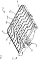
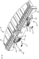
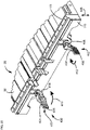
FIG. 2 is a perspective view of an embodiment of a table and fence, the fence being depicted in the operating position; -
FIG. 3 is a perspective view of the table and fence ofFIG. 2 , the fence being shown in a bypass position; -
FIG. 4 is a front view of the table and fence ofFIG. 2 ; -
FIG. 5 is a front view of the table and fence ofFIG. 3 ; -
FIG. 6 is a top plan view of the table and fence ofFIG. 2 ; -
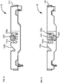
FIG. 7 is a cross-sectional view of the table and fence ofFIG. 6 , the cross-section being taken along the line A-A ofFIG. 6 ; -
FIG. 8 is a cross-sectional view of the table and fence ofFIG. 6 , showing the fence in a bypass position; -
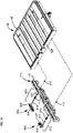
FIG. 9 is an exploded, perspective view of the table and fence ofFIG. 2 ; -
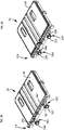
FIG. 10 is a perspective view of another embodiment of a table and fence, the fence being depicted in the operating position; -
FIG. 11 is a perspective view of the table and fence ofFIG. 10 , the fence being shown in a bypass position; -
FIG. 12 is an exploded perspective view of the table and fence ofFIGS. 10 and 11 ; -
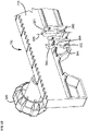
FIG. 13 is an enlarged, fragmented perspective view of a portion of the fence of the embodiment ofFIGS. 10-12 ; -
FIG. 14 is a perspective view of a fourth embodiment of a table and fence, with a portion of the table shown, and the fence being in the bypass position; -
FIG. 15 is a perspective view of the table and fence ofFIG. 14 , the fence being shown in the operating position; -
FIG. 16 is an exploded perspective view of the table and fence ofFIGS. 14 and15 ; -
FIG. 17 is a cross-sectional, perspective view of a portion of the table and fence ofFIGS. 14 and15 ; and -
FIG. 18 is an enlarged, fragmented perspective view of a portion of the fence of the embodiment ofFIGS. 14-16 . - This invention provides a wet tile saw 10 that can be used to accurately and quickly cut construction materials, such as ceramic, marble, or granite tiles, and the like. The wet tile saw 10 employs a lubricant, such as water, to cool a
cutting blade 15 and to carry away debris removed during the cutting process. As illustrated inFIG. 1 , the wet tile saw 10 includes asaw 20, a table 25, aframe 30, apan 35, and anextension 40. - The
frame 30 is a structural component that includes one or more rails 50 (e.g., a pair of rails) that extend along alongitudinal axis 55 of the tile saw 10, the one ormore rails 50 defining a guide. In some embodiments, at least tworails 50 are spaced apart from one another such that they are an opposite sides of theframe 30. - The table 25 may include a substantially planar
top surface 95 that is arranged to support aworkpiece 135, such as a piece of tile (shown schematically inFIG. 1 ) to be cut. Theworkpiece 135 may extend beyond the edges of the table 25 in some embodiments, and include a greatest dimension (e.g., a maximum length, a maximum width, and/or the like) that is at least about 30.48cm (12") more, at least about 60.96cm (24") more, at least about 91.44cm (36") more, and/or the like. Theworkpiece 135 may include a square shape, a rectangular shape, and/or the like. - The
top surface 95 includes a plurality of grooves orslots 100 arranged to direct the liquid coolant and collected cutting debris off the table 25 and into thepan 35. In addition, the table 25 includes multiple slots 105 (e.g., two slots 105, three slots 105, and/or the like) that extend parallel to thesaw axis 55 and that are shaped to receive thecutting blade 15 during a cut. Afirst slot 105a is arranged to receive theblade 15 during a vertical cut and is therefore substantially vertical. Asecond slot 105b is angled at a first angle, such as 45° from vertical, to receive thesaw blade 15 during a bevel cut at the first angle. Athird slot 105c is arranged at a second angle, such as 60° from vertical, to receive thesaw blade 15 during a bevel cut at the second angle. Additional slots 105 may be provided at different angles, if desired. - The
extension 40 is configured to attach to thepan 35, theframe 30, and/or a stand (not shown) and extends beyond thepan 35 behind thesaw 20. Theextension 40 functions as awater tray 45 and is angled to catch lubricant that splashes in the rearward direction and direct the lubricant back to thepan 35. Thewater tray 45 is on a side of thesaw 20 opposite of thecutting blade 15. - The table 25 includes a
rear fence 110. Therear fence 110 is configured to provide support for theworkpiece 135 as theworkpiece 135 is pushed, or otherwise moved, into theblade 15 during a cutting operation. As is described further below, therear fence 110 has an engagement surface 115 (FIGS. 7 ,9 ,12 and13 ) that is adjustable via sliding between an operating position and a bypassed position (the bypassed position being shown inFIG. 1 ). Thefence 110 is described in detail further below. - The operating position includes the
engagement surface 115 of therear fence 110 fixed to project upward from the planartop surface 95 of the table 25 to supportworkpiece 135, such as tile, as theworkpiece 135 is pushed into thecutting blade 15 during operation.FIGS. 2 ,4 ,7 , and10 show theengagement surface 115 of therear fence 110 in the operating position. In the operating position, the table 25 will move along therails 50 along the axis 55 (FIG. 1 ) in a direction toward thecutting blade 15, with theengagement surface 115 engaged against (e.g., abutting) the workpiece. - The bypassed position includes the
engagement surface 115 of therear fence 110 no higher than even with the planartop surface 95 of the table 25. That is, in some embodiments theengagement surface 115 of therear fence 110 may be substantially even with and, thus, substantially planar with the planartop surface 95 of the table 25. In some embodiments, theengagement surface 115 of therear fence 110 may be lower than and non-planar with the planartop surface 95 of the table 25. This layout allows theworkpiece 135 to extend beyond a rear edge 125 (FIG. 1 ) of the table 25. In this way,larger workpieces 135 may be accommodated for cutting by thesaw 20. InFIG. 1 , theworkpiece 135, shown schematically, extends beyond therear edge 125 of the table 25. This position of theworkpiece 135 is possible because theengagement surface 115 does not extend higher than the planartop surface 95 of the table 25. The bypassed position is shown inFIGS. 1 ,3 ,5 ,8 , and11 . - When the
engagement surface 115 of therear fence 110 is in the bypass position, a rip guide 145 (FIG. 1 ) having anengagement surface 146 parallel to the plane of thecutting blade 115 and theaxis 55 is used to abut against an edge of theworkpiece 135. The position of therip guide 145 is adjustable, and can be selectively moved or translated or slid by the user into an abutting engagement against an edge of theworkpiece 135. - When the
engagement surface 115 of therear fence 110 is in the bypassed position, the table 25 may be fixed relative to theframe 30. Theworkpiece 135 may be moved into thecutting blade 15 by the user pushing theworkpiece 135 across thetop surface 95 of the table 25 and into thecutting blade 15. - Reference is now made to the embodiment of
FIGS. 2-9 . In this embodiment, according to the invention, therear fence 110 is slidable and, thus, linearly translatable between the operating position (FIGS. 2 ,4 , and7 ) and the bypassed position (FIGS. 3 ,5 , and8 .) - The
engagement surface 115 of therear fence 110 remains perpendicular, or substantially perpendicular (i.e., within about +/- 15° of being perpendicular), to the planartop surface 95 of the table 25, when in both the operating position and the bypassed position. Theengagement surface 115 is also within a plane that is perpendicular, or substantially perpendicular, to the plane containing thecutting blade 15. Theengagement surface 115 is adjustable between the operating position and the bypass position by a pin andguideway arrangement 200. The pin andguideway arrangement 200 selectively holds therear fence 110 in the operating position and releases therear fence 110 to the bypassed position. - Many embodiments are possible. In the embodiment shown, the pin and
guideway arrangement 200 includes a guideway 205 (FIGS. 7-9 ) defined within thefence 110. Aknobbed pin 210 is adjustable within theguideway 205 to selectively fix therear fence 110 in one of the operating position and bypassed position. - The knobbed
pin 210 includes a threaded section 215 (FIG. 9 ) and aturn knob 220. Theguideway 205 is shaped so that thepin 210 can be moved therewithin, and the end of thepin 210 can be positioned within anaperture 225 along therear face 195 of the table 25. - In use, when the user desires to move the
rear fence 110 from the operating position to the bypass position, the user may rotate theknob 220 in a direction away from therear fence 110. This allows thepin 210 to be moved within theguideway 205 from the operating position ofFIG. 7 to the bypass position ofFIG. 8 . Theknob 220 can then be rotated in a direction toward therear fence 110 to tighten theknob 220 against thefence 110 and secure thepin 210 in its position in theguideway 205 and within theaperture 225. - Reference is now made to the embodiment of
FIGS. 10-13 . In this embodiment, therear fence 110 is slidable between the operating position (FIG. 10 ) and the bypassed position (FIG. 11 ). - The
engagement surface 115 of therear fence 110 remains perpendicular to the planartop surface 95 of the table 25, when in both the operating position and the bypassed position. Theengagement surface 115 is also within a plane that is perpendicular to the plane containing thecutting blade 15. Theengagement surface 115 is adjustable between the operating position and the bypass position by a pin andguideway arrangement 300. The pin andguideway arrangement 300 selectively holds therear fence 110 in the operating position and releases therear fence 110 to the bypassed position. - Many embodiments are possible. In the embodiment shown, the pin and
guideway arrangement 300 includes aguideway 301 embodied as at least a first elongated throughslot 305 defined by thefence 110. Theslot 305 has a longitudinal axis 306 (FIG. 13 ) perpendicular to a plane containing the planartop surface 95 of the table 25. Apin 310 includes a first threadedbolt 312 secured to the table 25 and has afirst turn knob 320 threadably connected to thefirst bolt 312. Theslot 305 is movable about thepin 310 to selectively fix therear fence 110 in one of the operating position and bypassed position. - While only a single pin and
guideway arrangement 300 can be used, in the embodiment shown, there may additionally be a second elongated throughslot 330 and a second threadedbolt 332 with asecond turn knob 334, functioning the same as thefirst slot 305,first bolt 312, andfirst turn knob 320. - In accordance with the invention, the tile saw 10 may additionally include a spring and
detent arrangement 340 for holding thefence 110 in the selected operating position or bypassed position. The spring anddetent arrangement 340 includes at least onespring 342 secured to either one of thefence 110 and arear face 195 of the table 25, and at least onedetent arrangement 344 positioned to engage thespring 342 defined by the other of thefence 110 andrear face 195 of the table 25. - In the embodiment shown, the at least one
spring 342 comprises aleaf spring 346 secured to therear face 195 of the table 25 and positioned to engage thedetent arrangement 344 defined by thefence 110 along the same surface as theengagement surface 115. While only a single spring anddetent arrangement 340 can be used, there may be twosprings rear face 195 of the table 25, and twodetent arrangements - Attention is directed to
FIG. 13 , which shows an enlarged view of thedetent arrangement 344. Thedetent arrangement 345 is structured the same asarrangement 344. Thedetent arrangement 344 includes anupper detent 350 and alower detent 352 with aslide surface 354 therebetween.Spring 342 slides between theupper detent 350 andlower detent 352 to hold thefence 110 in the selected bypassed position (FIG. 11 ) and operating position (FIG. 10 ) while the turn knobs 320, 334 are retightened. - In use, when the user desires to move the
rear fence 110 from the operating position to the bypass position, the user may rotate theknobs rear fence 110. This allows thefence 110 to be moved vertically so that theslots bolts FIG. 10 to the bypass position ofFIG. 11 . This also includes moving thefence 110 against thesprings lower detents 352 andupper detents 350. Theknobs rear fence 110 to tighten theknobs fence 110. - Reference is now made to the embodiment of
FIGS. 14-18 . In this embodiment, therear fence 110 is slidable between the operating position (FIG. 15 ) and the bypassed position (FIG. 14 ). In particular, therear fence 110 is slidable in an axial direction relative to the table 25 between the operating position and bypassed position. By "axial direction," it is meant that thefence 110 is slidable within a plane orthogonal to a plane containing the table 25. Seearrow 405 inFIG. 15 showing the direction of motion of thefence 110. - The
engagement surface 115 of therear fence 110 remains perpendicular, or substantially perpendicular, to the planartop surface 95 of the table 25, when in both the operating position and the bypassed position. Theengagement surface 115 is also within a plane that is perpendicular to the plane containing thecutting blade 15. In this embodiment, theengagement surface 115 is adjustable between the operating position and the bypass position by aclamp arrangement 400. Theclamp arrangement 400 selectively holds therear fence 110 in the selected position of either the operating position or the bypassed position. - Many embodiments are possible. In the embodiment shown, the
clamp arrangement 400 includes a pair of cam lever clamps 402, 403. Eachcam lever clamp pivot lever 404 with ahandle 406 and acam head 408. Thehandle 406 is sized to be gripped by a human hand and can be used to pivot thepivot lever 404 between a locked position and an unlocked position. In this embodiment, the locked position has thehandle 406 adjacent and generally parallel to the fence 110 (FIG. 14 ), while the unlocked position has thehandle 406 generally perpendicular to the fence 110 (FIG. 15 ). -
FIG. 14 showspivot arrows 410 indicating the direction of pivot from the locked position to the unlocked position, whileFIG. 15 showspivot arrows 412 indicating the direction of pivot from the unlocked position to the locked position. WhileFIG. 15 shows thefence 110 in the operating position and with thehandles 406 in the unlocked position, it should be understood that after adjusting thefence 110 to the operating position, thepivot lever 404 would be pivoted into the locked position (handles 406 adjacent to the fence 110) to lock thefence 110 in the operating position. -
FIGS. 16-18 show further details of theexample clamp arrangement 400. Thepivot lever 404 is secured to abolt 414 that is biased by aspring 416. Thebolt 414 extends through therear fence 110 and is movable along a vertically extending guide slot 422 (FIG. 18 ) in therear fence 110. Thebolt 414 extends into therear face 195 of the table 25. Anut 418 is securable on an end of thebolt 414 to keep the bolt attached to the table 25. Also visible inFIGS. 16 and17 is awasher 420 between thecam head 408 and thebolt 414, and alock washer 424 against thefence 110. While only thecam lever clamp 402 is shown inFIGS. 17 and18 , it should be understood that the assembly for thecam lever clamp 403 is the same. - In use, when the user desires to move the
rear fence 110 from the operating position to the bypass position, the user may pivot thepivot lever 404 by gripping thehandles 406 and moving in the direction ofarrows 410 from the locked position to the unlocked position. This motion rotates thecam head 408, which loosens the clamping force between the table 25 and thefence 110. Loosening of the clamping force allows thefence 110 to be moved vertically from the operating position ofFIG. 15 to the bypass position ofFIG. 14 . This also includes moving theguide slots 422 in thefence 110 along thebolts 414. Thepivot lever 404 can then be pivoted back into the locked position in the direction ofarrows 412 to lock thefence 110 into the bypass position. - When the user desires to move the
rear fence 110 from the bypass position to the operating position, the user pivots thepivot lever 404 in the direction ofarrows 410 from the locked position to the unlocked position, which loosens the clamping force between the table 25 and thefence 110 and allows thefence 110 to be moved vertically from the bypass position ofFIG. 14 to the operating position ofFIG. 15 . After adjusting thefence 110 to the operating position, thepivot lever 404 can then be pivoted back into the locked position in the direction ofarrows 412 to lock thefence 110 into the operating position. - The tile saw 110 can be used in a method of adjusting the tile saw 110 to accommodate a long length of tile. The method includes providing
saw 20 havingcutting blade 15. Theframe 30 supports thesaw 20. Table 25 hasplanar surface 95 configured to the support theworkpiece 135, which can be tile.Rear fence 110 is secured to the table 25. The method includes the step of adjusting therear fence 110 from the operating position to the bypassed position by sliding theengagement surface 115 to a position no higher than even with theplanar surface 95 of the table 25 to allow theworkpiece 135, such as tile, to extend beyond therear edge 125 of the table 25. - The step of adjusting the
rear fence 110 includes sliding therear fence 110 between the operating position and bypass position. This may include the step of loosening aknob 220 to release therear fence 110 from the operating position and then sliding therear fence 110 to the bypassed position. - The step of loosening a
knob 220 can include loosening first andsecond knobs rear fence 110 from the operating position, and then sliding therear fence 110 to the bypassed position. - The step of sliding the
rear fence 110 between the operating position and bypassed position may also include moving thefence 110 against aspring 342 between a pair ofdetents - The step of sliding the
rear fence 110 between the operating position and bypassed position can include moving thefence 110 against a pair ofsprings spring detents - The step of adjusting the
rear fence 110 can include pivoting apivot lever 404 of acam lever clamp rear fence 110 and the table 25 and then sliding therear fence 110 to the bypassed position. - The above represents example principles. Many embodiments can be made using these principles, as far as they fall within the scope of the claims.
Claims (12)
- A tile saw (10) comprising:a saw (20) having a cutting blade (15);a frame (30) supporting the saw (20); anda table (25) having a planar surface (95) configured to support a workpiece, the table being slidable relative to the frame;a rear fence (110) secured to the table (25), the rear fence having an engagement surface (115) that is adjustable, between an operating position and a bypassed position, the rear fence (110) being slidable between the operating position and the bypassed position, wherein:when in the operating position, the engagement surface (115) of the rear fence (110) is fixed to project upwardly from the planar surface (95) of the table (25) to support the workpiece during a cutting operation; and when in the bypassed position, the engagement surface (115) of the rear fence (110) is no higher than even with the planar surface (95) of the table (25) to allow the workpiece to extend beyond a rear edge of the table (25),characterized in thatthe rear fence is slidable between the operating position and the bypassed position.
- The tile saw (10) of claim 1 wherein the engagement surface (115), when in the operating position, is disposed along a plane that is perpendicular to a plane containing the cutting plane.
- The tile saw (10) of any one of claims 1 and 2 wherein the engagement surface (115) of the rear fence (110), when in both the operating position and the bypassed position, is perpendicular to the planar surface (95) of the table (25).
- The tile saw (10) of any one of claims 1, 2 and 3 further comprising a pin and guideway arrangement (200, 300) arranged to selectively hold the rear fence (110) in the operating position and release the rear fence (110) to the bypassed position.
- The tile saw (10) of claim 4 wherein the pin and guideway arrangement (200, 300) includes:a guideway (205, 301) defined within the rear fence (110); anda knobbed pin (210, 310) adjustable within the guideway to selectively fix the rear fence (110) in one of the operating position and bypassed position.
- The tile saw (10) of any one of claims 1 and 2 further comprising a spring and detent arrangement (340) for holding the rear fence (110) in the selected operating position or the bypassed position, the spring and detent arrangement (340) including:at least one spring (342) secured to one of the rear fence (110) and a rear face (195) of the table (25); andat least one detent arrangement (344) positioned to engage the spring and defined by the other of the rear fence and rear face of the table (25).
- The tile saw (10) of any one of claims 1, 2 and 3, further comprising a clamp arrangement (400) arranged to selectively hold the rear fence (110) in one of the operating position and the bypassed position.
- The tile saw (10) of claim 7, wherein the clamp arrangement (400) comprises a cam lever clamp (402, 403) having a pivot lever (404) secured to a spring-biased bolt (414), the spring-biased bolt extending through the rear fence (110) and into a rear face (195) of the table.
- The tile saw (10) of any one of claims 1-8 further comprising:
a rip guide (145) secured to the table (25) having a rip guide engagement surface (146) in a plane parallel to a plane containing the cutting blade (15). - The tile saw (10) of any one of claims 1-8 further comprising a water tray (45) an a side of the saw (20) opposite of the table (25).
- The tile saw (10) of any one of claims 1-8, wherein the table (25) is fixed relative to the frame (30) when the rear fence (110) is in the bypassed position.
- A method of adjusting a tile saw (10) to accommodate a length of tile, the method comprising:providing a tile saw (10) of any one of claims 1-11; andsliding the rear fence (110) from the operating position to the bypassed position to slide the engagement surface (115) of the rear fence (110) to a position substantially even with the planar surface of the table (25) to allow the tile to extend beyond the rear edge of the table (25).
Applications Claiming Priority (2)
| Application Number | Priority Date | Filing Date | Title |
|---|---|---|---|
| US201862775691P | 2018-12-05 | 2018-12-05 | |
| US201962802475P | 2019-02-07 | 2019-02-07 |
Publications (2)
| Publication Number | Publication Date |
|---|---|
| EP3663062A1 EP3663062A1 (en) | 2020-06-10 |
| EP3663062B1 true EP3663062B1 (en) | 2022-08-03 |
Family
ID=68806680
Family Applications (1)
| Application Number | Title | Priority Date | Filing Date |
|---|---|---|---|
| EP19213837.8A Active EP3663062B1 (en) | 2018-12-05 | 2019-12-05 | Tile saw with adjustable fence and method of use |
Country Status (4)
| Country | Link |
|---|---|
| US (2) | US11958213B2 (en) |
| EP (1) | EP3663062B1 (en) |
| CN (1) | CN211762602U (en) |
| CA (1) | CA3063903A1 (en) |
Families Citing this family (5)
| Publication number | Priority date | Publication date | Assignee | Title |
|---|---|---|---|---|
| US11958213B2 (en) * | 2018-12-05 | 2024-04-16 | Techtronic Cordless Gp | Tile saw with adjustable fence and methods |
| USD969181S1 (en) * | 2019-09-30 | 2022-11-08 | Black & Decker, Inc. | Tile saw |
| TWI788745B (en) * | 2020-12-23 | 2023-01-01 | 力山工業股份有限公司 | Worktable assembly for tile cutter |
| TWI754499B (en) * | 2020-12-23 | 2022-02-01 | 力山工業股份有限公司 | Tile saw with retractable water tank |
| EP4326516A4 (en) * | 2021-04-22 | 2024-12-11 | Black & Decker, Inc. | TILE SAW |
Family Cites Families (23)
| Publication number | Priority date | Publication date | Assignee | Title |
|---|---|---|---|---|
| US4428159A (en) * | 1981-07-29 | 1984-01-31 | Sigetich John D | Portable, direct drive abrasive saw |
| US5090283A (en) | 1990-05-21 | 1992-02-25 | Noble Walter E | Saw table |
| US6637424B1 (en) | 1999-06-25 | 2003-10-28 | Carver Saw Co. | Cutting apparatus and methods of operation |
| US6439218B1 (en) * | 2000-06-01 | 2002-08-27 | Mk Diamond Products, Inc. | Cutting apparatus with a supporting table |
| US6752140B1 (en) | 2001-09-21 | 2004-06-22 | Carver Saw Co. | Apparatus and method for adjusting the cutting angle of a cutting tool |
| GB2389333A (en) | 2002-06-08 | 2003-12-10 | Black & Decker Inc | Mitre saw with adjustable fence |
| US6752139B2 (en) | 2002-08-13 | 2004-06-22 | Wy Peron Lee | Worktable for cutting machine |
| US7819044B2 (en) | 2002-10-01 | 2010-10-26 | Black & Decker Inc. | Fence arrangement for a slide miter saw |
| US20060266182A1 (en) | 2005-05-12 | 2006-11-30 | Shiraz Balolia | Fence extension for power saws |
| JP2010501361A (en) | 2006-08-18 | 2010-01-21 | マニフォールド・プロダクツ・エルエルシー | Saw adjustment mechanism |
| US8919235B2 (en) | 2009-03-17 | 2014-12-30 | Hitachi Koki Co., Ltd. | Cutting apparatus |
| TW201127548A (en) * | 2010-02-12 | 2011-08-16 | Durq Machinery Corp | Material blocking mechanism of table saw |
| TW201201937A (en) | 2010-07-07 | 2012-01-16 | Durq Machinery Corp | Material blocking device for table sawing machine |
| CN102335784B (en) | 2010-07-23 | 2014-04-16 | 南京德朔实业有限公司 | Cutting device |
| CN202780498U (en) | 2012-08-17 | 2013-03-13 | 浙江精深实业有限公司 | Lengthened worktable |
| CN103286378B (en) | 2013-05-09 | 2015-11-04 | 江苏苏美达五金工具有限公司 | A kind of diagonal cutting saw with extending platform |
| US11104028B2 (en) | 2014-08-18 | 2021-08-31 | Sawstop Holding Llc | Fences for table saws |
| CN106475978B (en) * | 2015-09-02 | 2019-03-08 | 南京德朔实业有限公司 | A combination of a workbench and a grid device and a table tool with the combination |
| CN205043250U (en) | 2015-10-26 | 2016-02-24 | 永康市开源动力工具有限公司 | Oblique fracture saw movable table extends positioner |
| TWI654064B (en) * | 2015-12-08 | 2019-03-21 | 力山工業股份有限公司 | Tile cutter with collapsible cutting head assembly |
| US10603819B2 (en) | 2015-12-16 | 2020-03-31 | Black & Decker Inc. | Tile saw |
| WO2018001094A1 (en) | 2016-06-30 | 2018-01-04 | 南京德朔实业有限公司 | Cutting tool |
| US11958213B2 (en) * | 2018-12-05 | 2024-04-16 | Techtronic Cordless Gp | Tile saw with adjustable fence and methods |
-
2019
- 2019-12-02 US US16/699,960 patent/US11958213B2/en active Active
- 2019-12-04 CA CA3063903A patent/CA3063903A1/en active Pending
- 2019-12-05 EP EP19213837.8A patent/EP3663062B1/en active Active
- 2019-12-05 CN CN201922168117.1U patent/CN211762602U/en not_active Expired - Fee Related
-
2024
- 2024-03-14 US US18/605,186 patent/US12485581B2/en active Active
Also Published As
| Publication number | Publication date |
|---|---|
| US20200180185A1 (en) | 2020-06-11 |
| US12485581B2 (en) | 2025-12-02 |
| US11958213B2 (en) | 2024-04-16 |
| CA3063903A1 (en) | 2020-06-05 |
| US20240217138A1 (en) | 2024-07-04 |
| CN211762602U (en) | 2020-10-27 |
| EP3663062A1 (en) | 2020-06-10 |
Similar Documents
| Publication | Publication Date | Title |
|---|---|---|
| US12485581B2 (en) | Tile saw with adjustable fence and methods | |
| EP2661342B1 (en) | Miter saw with adjustable fence | |
| EP2178682B1 (en) | A powered cutting apparatus | |
| US8424434B2 (en) | Universal fence for a power table saw | |
| EP1990156B1 (en) | A modular guard system for a power saw | |
| EP2965885B1 (en) | Tile or masonry saw assembly with double movement | |
| US20140318341A1 (en) | Saw with articuable side vice and stop | |
| GB2481866A (en) | Pivotable Rip Fence Providing Support for Large Workpieces | |
| CN103124610A (en) | Movable workholding mechanism | |
| US20140047967A1 (en) | Saw Base for Providing Straight And Bevel Cuts Having A Common Cut Line | |
| US8910552B2 (en) | Movable saw apparatus and method | |
| US7140361B1 (en) | Stone cutter having blade angle adjustment device | |
| US20220118641A1 (en) | Utilizing a fence assembly that provides surfaces at different angles | |
| TWI546142B (en) | Table saw with symmetrical rail baffle storage capacity | |
| US7011085B1 (en) | Brick clamp for masonry work | |
| WO2022226271A1 (en) | Tile saw | |
| US7335093B1 (en) | Blade sharpening holder | |
| AU2007201585B2 (en) | Table fence for a mitre saw with top table | |
| CN107398590A (en) | Toolroom machine, especially goose saw | |
| TWI314506B (en) | ||
| FI82624B (en) | FAESTMEKANISM FOER EN HJAELPANORDNING AV EN HANDCIRKELSAOG. | |
| KR200395499Y1 (en) | Control apparatus of grinding angle for blade of a knife using woodworking tool | |
| CA2619791C (en) | Blade sharpening holder | |
| SE525965C2 (en) | Cutting bench is for cutting insulating material and has bench top with a first straight line slot for guiding a cutting tool and straight line bar with a second straight line slot for guiding the cutting tool | |
| WO1979000339A1 (en) | Improvements to power tools |
Legal Events
| Date | Code | Title | Description |
|---|---|---|---|
| PUAI | Public reference made under article 153(3) epc to a published international application that has entered the european phase |
Free format text: ORIGINAL CODE: 0009012 |
|
| STAA | Information on the status of an ep patent application or granted ep patent |
Free format text: STATUS: THE APPLICATION HAS BEEN PUBLISHED |
|
| AK | Designated contracting states |
Kind code of ref document: A1 Designated state(s): AL AT BE BG CH CY CZ DE DK EE ES FI FR GB GR HR HU IE IS IT LI LT LU LV MC MK MT NL NO PL PT RO RS SE SI SK SM TR |
|
| AX | Request for extension of the european patent |
Extension state: BA ME |
|
| RIN1 | Information on inventor provided before grant (corrected) |
Inventor name: COSTANZO, NICHOLAS A. Inventor name: HART, MICHAEL Inventor name: NEVEL, ERIC M. |
|
| STAA | Information on the status of an ep patent application or granted ep patent |
Free format text: STATUS: REQUEST FOR EXAMINATION WAS MADE |
|
| 17P | Request for examination filed |
Effective date: 20201201 |
|
| RBV | Designated contracting states (corrected) |
Designated state(s): AL AT BE BG CH CY CZ DE DK EE ES FI FR GB GR HR HU IE IS IT LI LT LU LV MC MK MT NL NO PL PT RO RS SE SI SK SM TR |
|
| GRAP | Despatch of communication of intention to grant a patent |
Free format text: ORIGINAL CODE: EPIDOSNIGR1 |
|
| STAA | Information on the status of an ep patent application or granted ep patent |
Free format text: STATUS: GRANT OF PATENT IS INTENDED |
|
| INTG | Intention to grant announced |
Effective date: 20211123 |
|
| GRAJ | Information related to disapproval of communication of intention to grant by the applicant or resumption of examination proceedings by the epo deleted |
Free format text: ORIGINAL CODE: EPIDOSDIGR1 |
|
| STAA | Information on the status of an ep patent application or granted ep patent |
Free format text: STATUS: REQUEST FOR EXAMINATION WAS MADE |
|
| GRAP | Despatch of communication of intention to grant a patent |
Free format text: ORIGINAL CODE: EPIDOSNIGR1 |
|
| STAA | Information on the status of an ep patent application or granted ep patent |
Free format text: STATUS: GRANT OF PATENT IS INTENDED |
|
| INTC | Intention to grant announced (deleted) | ||
| INTG | Intention to grant announced |
Effective date: 20220310 |
|
| GRAS | Grant fee paid |
Free format text: ORIGINAL CODE: EPIDOSNIGR3 |
|
| GRAA | (expected) grant |
Free format text: ORIGINAL CODE: 0009210 |
|
| STAA | Information on the status of an ep patent application or granted ep patent |
Free format text: STATUS: THE PATENT HAS BEEN GRANTED |
|
| AK | Designated contracting states |
Kind code of ref document: B1 Designated state(s): AL AT BE BG CH CY CZ DE DK EE ES FI FR GB GR HR HU IE IS IT LI LT LU LV MC MK MT NL NO PL PT RO RS SE SI SK SM TR |
|
| REG | Reference to a national code |
Ref country code: AT Ref legal event code: REF Ref document number: 1508381 Country of ref document: AT Kind code of ref document: T Effective date: 20220815 Ref country code: CH Ref legal event code: EP |
|
| REG | Reference to a national code |
Ref country code: DE Ref legal event code: R096 Ref document number: 602019017734 Country of ref document: DE |
|
| REG | Reference to a national code |
Ref country code: IE Ref legal event code: FG4D |
|
| REG | Reference to a national code |
Ref country code: LT Ref legal event code: MG9D |
|
| REG | Reference to a national code |
Ref country code: NL Ref legal event code: MP Effective date: 20220803 |
|
| PG25 | Lapsed in a contracting state [announced via postgrant information from national office to epo] |
Ref country code: SE Free format text: LAPSE BECAUSE OF FAILURE TO SUBMIT A TRANSLATION OF THE DESCRIPTION OR TO PAY THE FEE WITHIN THE PRESCRIBED TIME-LIMIT Effective date: 20220803 Ref country code: RS Free format text: LAPSE BECAUSE OF FAILURE TO SUBMIT A TRANSLATION OF THE DESCRIPTION OR TO PAY THE FEE WITHIN THE PRESCRIBED TIME-LIMIT Effective date: 20220803 Ref country code: PT Free format text: LAPSE BECAUSE OF FAILURE TO SUBMIT A TRANSLATION OF THE DESCRIPTION OR TO PAY THE FEE WITHIN THE PRESCRIBED TIME-LIMIT Effective date: 20221205 Ref country code: NO Free format text: LAPSE BECAUSE OF FAILURE TO SUBMIT A TRANSLATION OF THE DESCRIPTION OR TO PAY THE FEE WITHIN THE PRESCRIBED TIME-LIMIT Effective date: 20221103 Ref country code: NL Free format text: LAPSE BECAUSE OF FAILURE TO SUBMIT A TRANSLATION OF THE DESCRIPTION OR TO PAY THE FEE WITHIN THE PRESCRIBED TIME-LIMIT Effective date: 20220803 Ref country code: LV Free format text: LAPSE BECAUSE OF FAILURE TO SUBMIT A TRANSLATION OF THE DESCRIPTION OR TO PAY THE FEE WITHIN THE PRESCRIBED TIME-LIMIT Effective date: 20220803 Ref country code: LT Free format text: LAPSE BECAUSE OF FAILURE TO SUBMIT A TRANSLATION OF THE DESCRIPTION OR TO PAY THE FEE WITHIN THE PRESCRIBED TIME-LIMIT Effective date: 20220803 Ref country code: FI Free format text: LAPSE BECAUSE OF FAILURE TO SUBMIT A TRANSLATION OF THE DESCRIPTION OR TO PAY THE FEE WITHIN THE PRESCRIBED TIME-LIMIT Effective date: 20220803 Ref country code: ES Free format text: LAPSE BECAUSE OF FAILURE TO SUBMIT A TRANSLATION OF THE DESCRIPTION OR TO PAY THE FEE WITHIN THE PRESCRIBED TIME-LIMIT Effective date: 20220803 |
|
| REG | Reference to a national code |
Ref country code: AT Ref legal event code: MK05 Ref document number: 1508381 Country of ref document: AT Kind code of ref document: T Effective date: 20220803 |
|
| PG25 | Lapsed in a contracting state [announced via postgrant information from national office to epo] |
Ref country code: PL Free format text: LAPSE BECAUSE OF FAILURE TO SUBMIT A TRANSLATION OF THE DESCRIPTION OR TO PAY THE FEE WITHIN THE PRESCRIBED TIME-LIMIT Effective date: 20220803 Ref country code: IS Free format text: LAPSE BECAUSE OF FAILURE TO SUBMIT A TRANSLATION OF THE DESCRIPTION OR TO PAY THE FEE WITHIN THE PRESCRIBED TIME-LIMIT Effective date: 20221203 Ref country code: HR Free format text: LAPSE BECAUSE OF FAILURE TO SUBMIT A TRANSLATION OF THE DESCRIPTION OR TO PAY THE FEE WITHIN THE PRESCRIBED TIME-LIMIT Effective date: 20220803 Ref country code: GR Free format text: LAPSE BECAUSE OF FAILURE TO SUBMIT A TRANSLATION OF THE DESCRIPTION OR TO PAY THE FEE WITHIN THE PRESCRIBED TIME-LIMIT Effective date: 20221104 |
|
| PG25 | Lapsed in a contracting state [announced via postgrant information from national office to epo] |
Ref country code: SM Free format text: LAPSE BECAUSE OF FAILURE TO SUBMIT A TRANSLATION OF THE DESCRIPTION OR TO PAY THE FEE WITHIN THE PRESCRIBED TIME-LIMIT Effective date: 20220803 Ref country code: RO Free format text: LAPSE BECAUSE OF FAILURE TO SUBMIT A TRANSLATION OF THE DESCRIPTION OR TO PAY THE FEE WITHIN THE PRESCRIBED TIME-LIMIT Effective date: 20220803 Ref country code: DK Free format text: LAPSE BECAUSE OF FAILURE TO SUBMIT A TRANSLATION OF THE DESCRIPTION OR TO PAY THE FEE WITHIN THE PRESCRIBED TIME-LIMIT Effective date: 20220803 Ref country code: CZ Free format text: LAPSE BECAUSE OF FAILURE TO SUBMIT A TRANSLATION OF THE DESCRIPTION OR TO PAY THE FEE WITHIN THE PRESCRIBED TIME-LIMIT Effective date: 20220803 Ref country code: AT Free format text: LAPSE BECAUSE OF FAILURE TO SUBMIT A TRANSLATION OF THE DESCRIPTION OR TO PAY THE FEE WITHIN THE PRESCRIBED TIME-LIMIT Effective date: 20220803 |
|
| REG | Reference to a national code |
Ref country code: DE Ref legal event code: R097 Ref document number: 602019017734 Country of ref document: DE |
|
| PG25 | Lapsed in a contracting state [announced via postgrant information from national office to epo] |
Ref country code: SK Free format text: LAPSE BECAUSE OF FAILURE TO SUBMIT A TRANSLATION OF THE DESCRIPTION OR TO PAY THE FEE WITHIN THE PRESCRIBED TIME-LIMIT Effective date: 20220803 Ref country code: EE Free format text: LAPSE BECAUSE OF FAILURE TO SUBMIT A TRANSLATION OF THE DESCRIPTION OR TO PAY THE FEE WITHIN THE PRESCRIBED TIME-LIMIT Effective date: 20220803 |
|
| PLBE | No opposition filed within time limit |
Free format text: ORIGINAL CODE: 0009261 |
|
| STAA | Information on the status of an ep patent application or granted ep patent |
Free format text: STATUS: NO OPPOSITION FILED WITHIN TIME LIMIT |
|
| PG25 | Lapsed in a contracting state [announced via postgrant information from national office to epo] |
Ref country code: AL Free format text: LAPSE BECAUSE OF FAILURE TO SUBMIT A TRANSLATION OF THE DESCRIPTION OR TO PAY THE FEE WITHIN THE PRESCRIBED TIME-LIMIT Effective date: 20220803 |
|
| 26N | No opposition filed |
Effective date: 20230504 |
|
| REG | Reference to a national code |
Ref country code: CH Ref legal event code: PL |
|
| REG | Reference to a national code |
Ref country code: BE Ref legal event code: MM Effective date: 20221231 |
|
| PG25 | Lapsed in a contracting state [announced via postgrant information from national office to epo] |
Ref country code: SI Free format text: LAPSE BECAUSE OF FAILURE TO SUBMIT A TRANSLATION OF THE DESCRIPTION OR TO PAY THE FEE WITHIN THE PRESCRIBED TIME-LIMIT Effective date: 20220803 Ref country code: LU Free format text: LAPSE BECAUSE OF NON-PAYMENT OF DUE FEES Effective date: 20221205 |
|
| PG25 | Lapsed in a contracting state [announced via postgrant information from national office to epo] |
Ref country code: LI Free format text: LAPSE BECAUSE OF NON-PAYMENT OF DUE FEES Effective date: 20221231 Ref country code: IE Free format text: LAPSE BECAUSE OF NON-PAYMENT OF DUE FEES Effective date: 20221205 Ref country code: CH Free format text: LAPSE BECAUSE OF NON-PAYMENT OF DUE FEES Effective date: 20221231 |
|
| PG25 | Lapsed in a contracting state [announced via postgrant information from national office to epo] |
Ref country code: BE Free format text: LAPSE BECAUSE OF NON-PAYMENT OF DUE FEES Effective date: 20221231 |
|
| PG25 | Lapsed in a contracting state [announced via postgrant information from national office to epo] |
Ref country code: HU Free format text: LAPSE BECAUSE OF FAILURE TO SUBMIT A TRANSLATION OF THE DESCRIPTION OR TO PAY THE FEE WITHIN THE PRESCRIBED TIME-LIMIT; INVALID AB INITIO Effective date: 20191205 |
|
| PG25 | Lapsed in a contracting state [announced via postgrant information from national office to epo] |
Ref country code: CY Free format text: LAPSE BECAUSE OF FAILURE TO SUBMIT A TRANSLATION OF THE DESCRIPTION OR TO PAY THE FEE WITHIN THE PRESCRIBED TIME-LIMIT Effective date: 20220803 |
|
| PG25 | Lapsed in a contracting state [announced via postgrant information from national office to epo] |
Ref country code: MK Free format text: LAPSE BECAUSE OF FAILURE TO SUBMIT A TRANSLATION OF THE DESCRIPTION OR TO PAY THE FEE WITHIN THE PRESCRIBED TIME-LIMIT Effective date: 20220803 Ref country code: IT Free format text: LAPSE BECAUSE OF FAILURE TO SUBMIT A TRANSLATION OF THE DESCRIPTION OR TO PAY THE FEE WITHIN THE PRESCRIBED TIME-LIMIT Effective date: 20220803 |
|
| PG25 | Lapsed in a contracting state [announced via postgrant information from national office to epo] |
Ref country code: MC Free format text: LAPSE BECAUSE OF FAILURE TO SUBMIT A TRANSLATION OF THE DESCRIPTION OR TO PAY THE FEE WITHIN THE PRESCRIBED TIME-LIMIT Effective date: 20220803 |
|
| PG25 | Lapsed in a contracting state [announced via postgrant information from national office to epo] |
Ref country code: MC Free format text: LAPSE BECAUSE OF FAILURE TO SUBMIT A TRANSLATION OF THE DESCRIPTION OR TO PAY THE FEE WITHIN THE PRESCRIBED TIME-LIMIT Effective date: 20220803 |
|
| PG25 | Lapsed in a contracting state [announced via postgrant information from national office to epo] |
Ref country code: BG Free format text: LAPSE BECAUSE OF FAILURE TO SUBMIT A TRANSLATION OF THE DESCRIPTION OR TO PAY THE FEE WITHIN THE PRESCRIBED TIME-LIMIT Effective date: 20220803 |
|
| PG25 | Lapsed in a contracting state [announced via postgrant information from national office to epo] |
Ref country code: MT Free format text: LAPSE BECAUSE OF FAILURE TO SUBMIT A TRANSLATION OF THE DESCRIPTION OR TO PAY THE FEE WITHIN THE PRESCRIBED TIME-LIMIT Effective date: 20220803 |
|
| PG25 | Lapsed in a contracting state [announced via postgrant information from national office to epo] |
Ref country code: TR Free format text: LAPSE BECAUSE OF FAILURE TO SUBMIT A TRANSLATION OF THE DESCRIPTION OR TO PAY THE FEE WITHIN THE PRESCRIBED TIME-LIMIT Effective date: 20220803 |
|
| PGFP | Annual fee paid to national office [announced via postgrant information from national office to epo] |
Ref country code: GB Payment date: 20251229 Year of fee payment: 7 |
|
| PGFP | Annual fee paid to national office [announced via postgrant information from national office to epo] |
Ref country code: FR Payment date: 20251226 Year of fee payment: 7 |
|
| PGFP | Annual fee paid to national office [announced via postgrant information from national office to epo] |
Ref country code: DE Payment date: 20251229 Year of fee payment: 7 |