EP3662992A2 - Method for mixing heat dissipation material components - Google Patents
Method for mixing heat dissipation material components Download PDFInfo
- Publication number
- EP3662992A2 EP3662992A2 EP18847588.3A EP18847588A EP3662992A2 EP 3662992 A2 EP3662992 A2 EP 3662992A2 EP 18847588 A EP18847588 A EP 18847588A EP 3662992 A2 EP3662992 A2 EP 3662992A2
- Authority
- EP
- European Patent Office
- Prior art keywords
- heat
- dissipating material
- mixing
- static mixer
- viscosity
- Prior art date
- Legal status (The legal status is an assumption and is not a legal conclusion. Google has not performed a legal analysis and makes no representation as to the accuracy of the status listed.)
- Granted
Links
Images


Classifications
-
- B—PERFORMING OPERATIONS; TRANSPORTING
- B01—PHYSICAL OR CHEMICAL PROCESSES OR APPARATUS IN GENERAL
- B01F—MIXING, e.g. DISSOLVING, EMULSIFYING OR DISPERSING
- B01F25/00—Flow mixers; Mixers for falling materials, e.g. solid particles
- B01F25/40—Static mixers
- B01F25/42—Static mixers in which the mixing is affected by moving the components jointly in changing directions, e.g. in tubes provided with baffles or obstructions
- B01F25/43—Mixing tubes, e.g. wherein the material is moved in a radial or partly reversed direction
- B01F25/431—Straight mixing tubes with baffles or obstructions that do not cause substantial pressure drop; Baffles therefor
-
- B—PERFORMING OPERATIONS; TRANSPORTING
- B29—WORKING OF PLASTICS; WORKING OF SUBSTANCES IN A PLASTIC STATE IN GENERAL
- B29B—PREPARATION OR PRETREATMENT OF THE MATERIAL TO BE SHAPED; MAKING GRANULES OR PREFORMS; RECOVERY OF PLASTICS OR OTHER CONSTITUENTS OF WASTE MATERIAL CONTAINING PLASTICS
- B29B7/00—Mixing; Kneading
- B29B7/30—Mixing; Kneading continuous, with mechanical mixing or kneading devices
- B29B7/32—Mixing; Kneading continuous, with mechanical mixing or kneading devices with non-movable mixing or kneading devices
- B29B7/325—Static mixers
-
- B—PERFORMING OPERATIONS; TRANSPORTING
- B01—PHYSICAL OR CHEMICAL PROCESSES OR APPARATUS IN GENERAL
- B01F—MIXING, e.g. DISSOLVING, EMULSIFYING OR DISPERSING
- B01F35/00—Accessories for mixers; Auxiliary operations or auxiliary devices; Parts or details of general application
- B01F35/20—Measuring; Control or regulation
- B01F35/21—Measuring
- B01F35/213—Measuring of the properties of the mixtures, e.g. temperature, density or colour
-
- B—PERFORMING OPERATIONS; TRANSPORTING
- B01—PHYSICAL OR CHEMICAL PROCESSES OR APPARATUS IN GENERAL
- B01F—MIXING, e.g. DISSOLVING, EMULSIFYING OR DISPERSING
- B01F27/00—Mixers with rotary stirring devices in fixed receptacles; Kneaders
- B01F27/05—Stirrers
-
- B—PERFORMING OPERATIONS; TRANSPORTING
- B01—PHYSICAL OR CHEMICAL PROCESSES OR APPARATUS IN GENERAL
- B01F—MIXING, e.g. DISSOLVING, EMULSIFYING OR DISPERSING
- B01F27/00—Mixers with rotary stirring devices in fixed receptacles; Kneaders
- B01F27/05—Stirrers
- B01F27/051—Stirrers characterised by their elements, materials or mechanical properties
-
- B—PERFORMING OPERATIONS; TRANSPORTING
- B01—PHYSICAL OR CHEMICAL PROCESSES OR APPARATUS IN GENERAL
- B01F—MIXING, e.g. DISSOLVING, EMULSIFYING OR DISPERSING
- B01F35/00—Accessories for mixers; Auxiliary operations or auxiliary devices; Parts or details of general application
- B01F35/20—Measuring; Control or regulation
-
- B—PERFORMING OPERATIONS; TRANSPORTING
- B01—PHYSICAL OR CHEMICAL PROCESSES OR APPARATUS IN GENERAL
- B01F—MIXING, e.g. DISSOLVING, EMULSIFYING OR DISPERSING
- B01F35/00—Accessories for mixers; Auxiliary operations or auxiliary devices; Parts or details of general application
- B01F35/20—Measuring; Control or regulation
- B01F35/22—Control or regulation
- B01F35/221—Control or regulation of operational parameters, e.g. level of material in the mixer, temperature or pressure
- B01F35/2211—Amount of delivered fluid during a period
-
- B—PERFORMING OPERATIONS; TRANSPORTING
- B01—PHYSICAL OR CHEMICAL PROCESSES OR APPARATUS IN GENERAL
- B01F—MIXING, e.g. DISSOLVING, EMULSIFYING OR DISPERSING
- B01F35/00—Accessories for mixers; Auxiliary operations or auxiliary devices; Parts or details of general application
- B01F35/20—Measuring; Control or regulation
- B01F35/22—Control or regulation
- B01F35/221—Control or regulation of operational parameters, e.g. level of material in the mixer, temperature or pressure
- B01F35/2216—Time, i.e. duration, of at least one parameter during the operation
-
- B—PERFORMING OPERATIONS; TRANSPORTING
- B29—WORKING OF PLASTICS; WORKING OF SUBSTANCES IN A PLASTIC STATE IN GENERAL
- B29B—PREPARATION OR PRETREATMENT OF THE MATERIAL TO BE SHAPED; MAKING GRANULES OR PREFORMS; RECOVERY OF PLASTICS OR OTHER CONSTITUENTS OF WASTE MATERIAL CONTAINING PLASTICS
- B29B7/00—Mixing; Kneading
- B29B7/30—Mixing; Kneading continuous, with mechanical mixing or kneading devices
- B29B7/58—Component parts, details or accessories; Auxiliary operations
- B29B7/72—Measuring, controlling or regulating
- B29B7/726—Measuring properties of mixture, e.g. temperature or density
-
- B—PERFORMING OPERATIONS; TRANSPORTING
- B29—WORKING OF PLASTICS; WORKING OF SUBSTANCES IN A PLASTIC STATE IN GENERAL
- B29B—PREPARATION OR PRETREATMENT OF THE MATERIAL TO BE SHAPED; MAKING GRANULES OR PREFORMS; RECOVERY OF PLASTICS OR OTHER CONSTITUENTS OF WASTE MATERIAL CONTAINING PLASTICS
- B29B7/00—Mixing; Kneading
- B29B7/30—Mixing; Kneading continuous, with mechanical mixing or kneading devices
- B29B7/58—Component parts, details or accessories; Auxiliary operations
- B29B7/72—Measuring, controlling or regulating
- B29B7/728—Measuring data of the driving system, e.g. torque, speed, power, vibration
-
- B—PERFORMING OPERATIONS; TRANSPORTING
- B29—WORKING OF PLASTICS; WORKING OF SUBSTANCES IN A PLASTIC STATE IN GENERAL
- B29B—PREPARATION OR PRETREATMENT OF THE MATERIAL TO BE SHAPED; MAKING GRANULES OR PREFORMS; RECOVERY OF PLASTICS OR OTHER CONSTITUENTS OF WASTE MATERIAL CONTAINING PLASTICS
- B29B7/00—Mixing; Kneading
- B29B7/80—Component parts, details or accessories; Auxiliary operations
- B29B7/88—Adding charges, i.e. additives
- B29B7/90—Fillers or reinforcements, e.g. fibres
-
- C—CHEMISTRY; METALLURGY
- C09—DYES; PAINTS; POLISHES; NATURAL RESINS; ADHESIVES; COMPOSITIONS NOT OTHERWISE PROVIDED FOR; APPLICATIONS OF MATERIALS NOT OTHERWISE PROVIDED FOR
- C09J—ADHESIVES; NON-MECHANICAL ASPECTS OF ADHESIVE PROCESSES IN GENERAL; ADHESIVE PROCESSES NOT PROVIDED FOR ELSEWHERE; USE OF MATERIALS AS ADHESIVES
- C09J11/00—Features of adhesives not provided for in group C09J9/00, e.g. additives
- C09J11/02—Non-macromolecular additives
- C09J11/04—Non-macromolecular additives inorganic
Definitions
- the present invention relates to a method for mixing a heat-dissipating material.
- a battery, a television, a video, a computer, a medical instrument, an office machine or a communication device, and the like generates heat during operation and a temperature rise due to the heat causes operation failure or destruction, and the like, so that a heat-dissipating method for suppressing the temperature rise or a heat-dissipating member used for the method, and the like has been proposed.
- the heat source adheres to the cooling medium or the heat sink as close as possible or is thermally connected thereto, and a heat-dissipating material can be used for this purpose.
- the capacity of the mixer should be optimized according to mixing efficiency or reaction rates.
- a method for mixing a heat-dissipating material comprising a room-temperature curing filler with a static mixer
- the method for mixing a heat-dissipating material comprises a step of determining a capacity (V) of the static mixer based on an injection amount (Q) per process unit time, a process unit time (td) and a time (t2) during which the viscosity of the heat-dissipating material flowing out of the static mixer becomes twice the initial mixing viscosity, where when the heat-dissipating material is sequentially injected into first and second external devices with the static mixer, the process unit time is the difference between the time on which the heat-dissipating material starts to be injected into the second external device and the time on which the heat-dissipating material starts to be injected into the first external device.
- V The capacity (V) of the static mixer can be determined by Equation 1 below.
- the unit of the capacity of the static mixer may be ml
- the unit of the injection amount (Q) may be ml
- the unit of the process unit time (td) and the time (t2) during which the viscosity becomes twice the initial mixing viscosity may be min.
- the mixing method may further comprise a step of performing mixing of the heat-dissipating material at a Reynolds number (Re) of 10 to 1000.
- the static mixer may have a number of elements of 5 to 25.
- the time (t2) during which the viscosity becomes twice the initial mixing viscosity may be 1 to 10 minutes.
- the time (t2) during which the viscosity becomes twice the initial mixing viscosity may be measured in the following method.
- the heat-dissipating material flowing out of the static mixer is measured in a frequency sweep mode using an ARES (advanced rheometric expansion system), which is a rheological property measuring device, within one minute, but the mixed viscosity at a shear rate of 2.5/s is measured, and the mixed viscosities are measured three times or more over time, and then the time during which the viscosity is doubled as compared with the initial viscosity can be obtained through plot based on the measured mixed viscosities.
- ARES advanced rheometric expansion system
- the heat-dissipating material may have a thermal conductivity of 1.0 W/mK or more.
- the heat-dissipating material may have a viscosity of 10 to 300,000 cP.
- Each of the first and second external devices may be a battery module.
- the capacity of each static mixer can be determined based on the injection amount (Q) per process unit time for each static mixer, the process unit time (td) and the time (t2) during which the viscosity of the heat-dissipating material flowing out of the static mixer becomes twice the initial mixing viscosity.
- the respective static mixers can be determined to have the same capacity.
- the mixing method of the heat-dissipating material related to one example of the present invention has the following effect.
- the capacity (V) of the static mixer can be determined based on the injection amount (Q) per process unit time for each static mixer, the process unit time (td) and the time (t2) during which the viscosity becomes twice the initial mixing viscosity, whereby the capacity of the static mixer can be optimized.
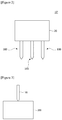
- Figure 1 is a schematic diagram showing a dispensing apparatus (10) used in a mixing method of a heat-dissipating material related to one example of the present invention
- Figure 2 is a schematic diagram showing another embodiment of a dispensing apparatus (10')
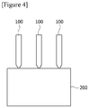
- Figures 3 and 4 are schematic diagrams showing embodiments in which a heat-dissipating material is injected into a first external device (200).
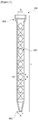
- Figure 5 is a schematic diagram of the static mixer (100) shown in Figure 1 .
- the mixing method of a heat-dissipating material related to one example of the present invention is a method for mixing a heat-dissipating material comprising a room-temperature curing filler with a plurality of static mixers.
- a heat-dissipating material related to the present invention may be injected into an external device (200, 300) through a dispensing apparatus (10).
- the dispensing apparatus (10) comprises a dispensing part (20) and one or more static mixers (100) connected to the dispensing part (20).
- the external device may be a battery module.
- the first external device refers to a first battery module and the second external device refers to a second battery module.
- the first and second battery modules are merely terms that are stated separately in order to explain process units in turn, and have the same structure.
- the production method of the battery module may comprise steps of providing a battery module, mixing a heat-dissipating material and injecting the heat-dissipating material. At this time, the mixing and the injection of the heat-dissipating material are performed through static mixers. In addition, the mixing of the heat-dissipating material may be performed in each static mixer (100), and the injection of the heat-dissipating material for one battery module may be performed through a plurality of static mixers (100).
- Figure 6 is a schematic diagram of a module case (210) constituting a battery module
- Figure 7 is a schematic diagram showing a battery module (200)
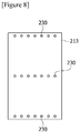
- Figure 8 is a schematic diagram for explaining injection holes (230) of a module case.
- the battery module (200) comprises a module case (210) and a plurality of battery cells (220) disposed in the module case (210).
- the battery cell (220) may be a pouch-type secondary battery.
- the battery cell (200) may typically comprise an electrode assembly, an electrolyte, and a pouch exterior material. The heat-dissipating material is injected into spaces between the battery cells in the module case and functions to dissipate heat generated in the battery cells (220).
- the module case (210) may have, for example, a cuboidal shape and may have a bottom surface (211), side surfaces (212) and a top surface (213). At this time, one or more injection holes (230) may be formed on the top surface (213). At this time, one static mixer (100) is connected to one injection hole (230), so that the heat-dissipating material flowing out of the static mixer (100) can be injected into the battery module (200) through the injection hole (230).
- the step of injecting a heat-dissipating material may be sequentially performed on a plurality of battery modules.
- the heat-dissipating material may be injected into the second battery module (300).
- the first and second battery modules (200, 300) are transferred by a transfer part (for example, a belt conveyor) and sequentially passed through the dispensing apparatus (100), whereby a heat-dissipating material can be injected.
- the heat-dissipating material may also be injected into one battery module (for example, the first battery module, 200) through one static mixer, and referring to Figure 4 , the heat-dissipating material may be injected into one battery module (for example, the first battery module, 200) through a plurality of static mixers (100).
- the dispensing apparatus (100) for mixing and injecting a heat-dissipating material comprises a dispensing part (20) and one or more static mixers (100) connected to the dispensing part (20).
- the heat-dissipating material mixed through the static mixer and injected into a battery module relates to a thermally conductive resin composition.
- the resin composition may comprise a resin component and a thermally conductive filler.
- the dispensing part (20) comprises a first supply cartridge portion (21) and a second supply cartridge portion (22). At this time, the first supply cartridge portion (21) and the second supply cartridge portion (22) are connected to the static mixer (100) individually.
- the first supply cartridge portion (21) supplies a main resin and a thermally conductive filler for forming a resin composition to the static mixer (100) and the second supply cartridge portion (22) supplies a curing agent and a thermally conductive filler to the static mixer (100).
- the static mixer (100) has an inflow part (101) and an outflow part (102).
- the inflow part (101) is provided to be separately connected to the first supply cartridge portion (21) and the second supply cartridge portion (22), and the outflow part (102) is provided to be connected to injection holes (230) provided at the module case (210) of the battery module (200).
- the static mixer (100) comprises a screw part (120) for mixing and transfer.
- the screw part (120) is composed of a plurality of elements (121) and one element (121) forms one stage (B), where the number of elements (121) can be referred to as a number of stages.
- the number of elements (121) of the static mixer (100) may be 5 to 25. If the number of elements (121) is insufficient, the mixing efficiency lowers, which may affect the curing speed, the adhesive force, the insulating property, and the like, or cause reliability problems. Alternatively, if the number of elements (121) is excessively large, a mixer having a small diameter and a long length is used to maintain the same mixer capacity, and thus the process speed is lowered.
- the static mixer (100) has a mixer inner diameter (D) of about 9mm, where the screw part (120) is disposed, a screw part (120) width of 5mm, an outflow part (102) diameter (A) of 3mm, a mixer length (L) of 225mm and a number of stages of 24.
- One example of the present invention provides a method of mixing and injecting a heat-dissipating material containing a room-temperature curing filler with a static mixer.
- the process unit time is the difference between the time on which the heat-dissipating material starts to be injected into the second external device and the time on which the heat-dissipating material starts to be injected into the first external device.
- the time on which the heat-dissipating material is injected into the first external device is 0:00
- the time on which the heat-dissipating material is injected into the second external device is 3:30, where the process unit time is 3 minutes.
- the mixing method of the heat-dissipating material comprises a step of determining a capacity (V) of the static mixer based on an injection amount (Q) per process unit time, a process unit time (td) and a time (t2) during which the viscosity of the heat-dissipating material flowing out of the static mixer (100) becomes twice the initial mixing viscosity.
- the capacity (V) of the static mixer (100) can be determined according to an injection amount (Q) per process unit time, in which a heat-dissipating material is injected into a battery module with a static mixer, a process unit time (td) and a time (t2) during which the viscosity of the heat-dissipating material flowing out of the static mixer (100) becomes twice the initial mixing viscosity.
- V The capacity (V) of the static mixer can be determined by Equation 1 below.
- the unit of the capacity of the static mixer may be ml
- the unit of the injection amount (Q) may be ml
- the unit of the process unit time (td) and the time (t2) during which the initial mixing viscosity is doubled may be min.
- the mixing method may further comprise a step of performing mixing of the heat-dissipating material at a Reynolds number (Re) of 10 to 1000.
- the static mixer may have 5 to 25 elements.
- the heat-dissipating material may have a thermal conductivity of 1.0 W/mK or more, and the heat radiation material may also have a viscosity of 10 to 300,000 cP.
- the capacity (100) of each static mixer can be determined based on an injection amount (Q) per process unit time for each static mixer (100), a process unit time (td) and a time (t2) during which the viscosity of the heat-dissipating material flowing out of the static mixer (100) becomes twice the initial mixing viscosity.
- the respective static mixers can be determined to have the same capacity.
- V The capacity (V) of each static mixer can be determined by Equation 1 below. V ⁇ t 2 / td ⁇ Q
- the unit of the capacity of the static mixer may be ml
- the unit of the injection amount (Q) may be ml
- the unit of the process unit time (td) and the time (t2) during which the initial mixing viscosity is doubled may be min.
- the heat-dissipating material relates to a thermally conductive resin composition.
- the resin composition may comprise a resin component and a thermally conductive filler.
- the resin composition may be an adhesive composition, for example, a composition capable of forming an adhesive through a curing reaction or the like.
- a resin composition may be a solvent type resin composition, a water-based resin composition, or a solventless-type resin composition.
- the resin composition may be prepared by compounding a thermally conductive filler, which is described below, to a resin composition capable of forming a known acrylic adhesive, epoxy adhesive, urethane adhesive, olefin adhesive, EVA (ethylene vinyl acetate) adhesive or silicone adhesive.
- resin component is generally used as a meaning to include components known as resins as well as components that can be converted into resins through a curing reaction or a polymerization reaction.
- an adhesive resin or a precursor capable of forming an adhesive resin can be applied as the resin component.
- a resin component includes an acrylic resin, an epoxy resin, a urethane resin, an olefin resin, an EVA (ethylene vinyl acetate) resin or a silicone resin, and the like, or a precursor such as a polyol or an isocyanate compound, and the like, but is not limited thereto.
- the resin composition may comprise a thermally conductive filler together with the resin component.
- thermally conductive filler means a material having a thermal conductivity of about 1 W/mK or more, about 5 W/mK or more, about 10 W/mK or more, or about 15 W/mK or more.
- the thermal conductivity of the thermally conductive filler may be about 400 W/mK or less, about 350 W/mK or less, or about 300 W/mK or less.
- the kind of thermally conductive filler is not particularly limited, but ceramic fillers may be applied in consideration of insulation and the like.
- ceramic particles such as alumina, AlN (aluminum nitride), BN (boron nitride), silicon nitride, SiC or BeO may be used. If insulation properties may be secured, application of carbon fillers such as graphite may also be considered.
- the resin composition may comprise about 600 parts by weight or more of the thermally conductive filler relative to 100 parts by weight of the resin component.
- the ratio of the filler may be 650 parts by weight or more, or 700 parts by weight or more, relative to 100 parts by weight of the resin component.
- the ratio may be about 2,000 parts by weight or less, about 1,500 parts by weight or less, or about 1,100 parts by weight or less, relative to 100 parts by weight of the resin component.
- Within the ratio range of the filler it is possible to secure desired physical properties such as thermal conductivity and insulation.
- the viscosity of the resin composition is greatly increased and accordingly, the handling property is lowered, and even after the resin material is formed, it contains bubbles or voids, so that the thermal conductivity may be deteriorated.
- a filler having at least three different diameters may be applied to the resin composition at a predetermined ratio.
- the shape of the filler is not particularly limited, which may be selected in consideration of viscosity and thixotropy of the resin composition, possibility of settling in the composition, the target thermal resistance or thermal conductivity, insulation, a filling effect or dispersibility, and the like.
- a spherical filler considering the amount to be filled, it is advantageous to use a spherical filler, but in consideration of formation of a network, conductivity, thixotropy and the like, a non-spherical filler, for example, a filler having a shape such as a needle shape or a plate shape can also be used.
- the resin composition basically comprises the above components, that is, the resin component and the thermally conductive filler, and if necessary, it may also comprise other components.
- the resin composition may further comprise a viscosity control agent, such as a thixotropic agent, a diluent, a dispersant, a surface treatment agent or a coupling agent, for control of viscosity, for example, for increasing or decreasing viscosity, or for control of viscosity according to shear force.
- a viscosity control agent such as a thixotropic agent, a diluent, a dispersant, a surface treatment agent or a coupling agent, for control of viscosity, for example, for increasing or decreasing viscosity, or for control of viscosity according to shear force.
- the thixotropic agent can control the viscosity according to the shear force of the resin composition so that the manufacturing process of the battery module can be effectively performed.
- the usable thixotropic agent can be exemplified by fumed silica and the like.
- the diluent or dispersant is usually used for lowering the viscosity of the resin composition, and any of various kinds known in the art can be used without limitation as long as it can exhibit the above action.
- the surface treating agent is used for surface treatment of the filler introduced into the resin composition, and any of various kinds known in the art can be used without limitation as long as it can exhibit the above action.
- the coupling agent may be used, for example, to improve the dispersibility of the thermally conductive filler such as alumina, and any of various kinds known in the art may be used without limitation as long as it can exhibit the above action.
- the resin composition may further comprise a flame retardant or a flame retardant auxiliary agent, and the like.
- a resin composition can form a flame retardant resin composition.
- various known flame retardants can be applied without particular limitation, and for example, a solid filler-shaped flame retardant or a liquid flame retardant, and the like can be applied.
- the flame retardant includes, for example, an organic flame retardant such as melamine cyanurate, or an inorganic flame retardant such as magnesium hydroxide, and the like, but is not limited thereto.
- a liquid type flame retardant material (TEP, triethyl phosphate or TCPP, tris(1,3-chloro-2-propyl) phosphate, etc.) may also be used.
- a silane coupling agent capable of acting as a flame retardant synergist may also be added.
- the heat-dissipating material may be a heat-dissipating filler high-viscosity two-component room-temperature curing urethane.
- the heat-dissipating material may have a thermal conductivity of 1.0 W/mK or more, and the heat-dissipating material may have a viscosity of 10 to 300,000 cP.
- the specific gravity may be 3 g/cm 3
- the mixer diameter may be 10mm
- the flow rate may be 0.25cm 3 /sec.
- the Reynolds number (Re) may be 58 and the number of elements may be 12. At this time, the lower the viscosity, the smaller the number of elements required. For example, when the viscosity is 100,000 to 1,000,000, the number of elements may be 12 to 25.
- the time (t2) during which the initial mixing viscosity is doubled may be 1 to 10 minutes
- the process unit time (td) may be 3 minutes
- the injection amount (Q) for each static mixer may be 30 ml.
- the static mixer maximum capacity (V) is 30 ml upon calculation by Equation 1.
- the curing speed is set to 100 as a normal curing speed at a target mixing ratio (for example, two-component type 1: 1), where on the basis of this, the speed according to the curing time under the same curing condition can be relativized. Also, as an actual process unit time is compared with a target process time, the processability is classified into "O” if the actual process unit time is equal to or faster than the target process time, and "X" if the actual process unit time is slower than that.
- a target mixing ratio for example, two-component type 1: 1
- the capacity of the static mixer can be optimized in correspondence with the heat-dissipating material.
Landscapes
- Chemical & Material Sciences (AREA)
- Chemical Kinetics & Catalysis (AREA)
- Mechanical Engineering (AREA)
- Engineering & Computer Science (AREA)
- Dispersion Chemistry (AREA)
- Organic Chemistry (AREA)
- Inorganic Chemistry (AREA)
- Cooling Or The Like Of Semiconductors Or Solid State Devices (AREA)
- Compositions Of Macromolecular Compounds (AREA)
- Accessories For Mixers (AREA)
- Secondary Cells (AREA)
- Processing And Handling Of Plastics And Other Materials For Molding In General (AREA)
- Cooling Or The Like Of Electrical Apparatus (AREA)
Abstract
Description
- The present invention relates to a method for mixing a heat-dissipating material.
- This application claims the benefit of priority based on Korean Patent Application No.
10-2017-0105933 filed on August 22, 2017 10-2018-0097733 filed on August 22, 2018 - A battery, a television, a video, a computer, a medical instrument, an office machine or a communication device, and the like generates heat during operation and a temperature rise due to the heat causes operation failure or destruction, and the like, so that a heat-dissipating method for suppressing the temperature rise or a heat-dissipating member used for the method, and the like has been proposed.
- For example, there is known a method in which heat is transferred to a cooling medium such as cooling water, or a temperature rise is suppressed through heat conduction to a heat sink using a metal plate or the like having a high thermal conductivity such as aluminum or copper.
- In order to efficiently transfer heat from a heat source to a cooling medium or a heat sink, it is advantageous that the heat source adheres to the cooling medium or the heat sink as close as possible or is thermally connected thereto, and a heat-dissipating material can be used for this purpose.
- For two-component room-temperature curing high-viscosity fluids in heat-dissipating materials, the capacity of the mixer should be optimized according to mixing efficiency or reaction rates.
- For example, if the number of mixers is excessively large or the length is long, the dispensing speed is adversely affected, whereas if the number or length is insufficient, the mixing efficiency is lowered, thereby resulting in deterioration of physical properties due to non-uniform cured products.
- It is a problem to be solved by the present invention to provide a method for mixing a heat-dissipating material that can optimize the capacity of a static mixer according to a heat-dissipating material.
- To solve the above-described problem, according to one aspect of the present invention, there is provided a method for mixing a heat-dissipating material comprising a room-temperature curing filler with a static mixer, wherein the method for mixing a heat-dissipating material comprises a step of determining a capacity (V) of the static mixer based on an injection amount (Q) per process unit time, a process unit time (td) and a time (t2) during which the viscosity of the heat-dissipating material flowing out of the static mixer becomes twice the initial mixing viscosity, where when the heat-dissipating material is sequentially injected into first and second external devices with the static mixer, the process unit time is the difference between the time on which the heat-dissipating material starts to be injected into the second external device and the time on which the heat-dissipating material starts to be injected into the first external device.
- The capacity (V) of the static mixer can be determined by Equation 1 below.

- In Equation 1, the unit of the capacity of the static mixer may be ml, the unit of the injection amount (Q) may be ml, and the unit of the process unit time (td) and the time (t2) during which the viscosity becomes twice the initial mixing viscosity may be min.
- The mixing method may further comprise a step of performing mixing of the heat-dissipating material at a Reynolds number (Re) of 10 to 1000.
- In addition, the static mixer may have a number of elements of 5 to 25.
- The time (t2) during which the viscosity becomes twice the initial mixing viscosity may be 1 to 10 minutes. On the other hand, the time (t2) during which the viscosity becomes twice the initial mixing viscosity may be measured in the following method. For example, the heat-dissipating material flowing out of the static mixer is measured in a frequency sweep mode using an ARES (advanced rheometric expansion system), which is a rheological property measuring device, within one minute, but the mixed viscosity at a shear rate of 2.5/s is measured, and the mixed viscosities are measured three times or more over time, and then the time during which the viscosity is doubled as compared with the initial viscosity can be obtained through plot based on the measured mixed viscosities.
- In addition, the heat-dissipating material may have a thermal conductivity of 1.0 W/mK or more.
- Also, the heat-dissipating material may have a viscosity of 10 to 300,000 cP.
- Each of the first and second external devices may be a battery module.
- Furthermore, when the heat-dissipating material is injected into the first external device with a plurality of static mixers, the capacity of each static mixer can be determined based on the injection amount (Q) per process unit time for each static mixer, the process unit time (td) and the time (t2) during which the viscosity of the heat-dissipating material flowing out of the static mixer becomes twice the initial mixing viscosity.
- In addition, when it is injected with a plurality of static mixers, the respective static mixers can be determined to have the same capacity.
- As described above, the mixing method of the heat-dissipating material related to one example of the present invention has the following effect.
- The capacity (V) of the static mixer can be determined based on the injection amount (Q) per process unit time for each static mixer, the process unit time (td) and the time (t2) during which the viscosity becomes twice the initial mixing viscosity, whereby the capacity of the static mixer can be optimized.
-
-
Figure 1 is a schematic diagram showing a dispensing apparatus used in a mixing method of a heat-dissipating material related to one example of the present invention. -
Figure 2 is a schematic diagram showing another embodiment of the dispensing apparatus. -
Figures 3 and4 are schematic diagrams showing embodiments in which a heat-dissipating material is injected into a first external device. -
Figure 5 is a schematic diagram of the static mixer shown inFigure 1 . -
Figure 6 is a schematic diagram of a module case constituting a battery module. -
Figure 7 is a schematic diagram showing a battery module. -
Figure 8 is a schematic diagram for explaining injection holes of a module case. - Hereinafter, a method for mixing a heat-dissipating material according to one example of the present invention will be described in detail with reference to the accompanying drawings.
- In addition, the same or similar reference numerals are given to the same or corresponding components regardless of reference numerals, of which redundant explanations will be omitted, and for convenience of explanation, the size and shape of each constituent member as shown may be exaggerated or reduced.
-
Figure 1 is a schematic diagram showing a dispensing apparatus (10) used in a mixing method of a heat-dissipating material related to one example of the present invention,Figure 2 is a schematic diagram showing another embodiment of a dispensing apparatus (10'), andFigures 3 and4 are schematic diagrams showing embodiments in which a heat-dissipating material is injected into a first external device (200). - Also,
Figure 5 is a schematic diagram of the static mixer (100) shown inFigure 1 . - The mixing method of a heat-dissipating material related to one example of the present invention is a method for mixing a heat-dissipating material comprising a room-temperature curing filler with a plurality of static mixers.
- Referring to
Figure 1 , a heat-dissipating material related to the present invention may be injected into an external device (200, 300) through a dispensing apparatus (10). The dispensing apparatus (10) comprises a dispensing part (20) and one or more static mixers (100) connected to the dispensing part (20). - The external device may be a battery module.
- In this document, the first external device refers to a first battery module and the second external device refers to a second battery module. The first and second battery modules are merely terms that are stated separately in order to explain process units in turn, and have the same structure.
- The production method of the battery module may comprise steps of providing a battery module, mixing a heat-dissipating material and injecting the heat-dissipating material. At this time, the mixing and the injection of the heat-dissipating material are performed through static mixers. In addition, the mixing of the heat-dissipating material may be performed in each static mixer (100), and the injection of the heat-dissipating material for one battery module may be performed through a plurality of static mixers (100).
-
Figure 6 is a schematic diagram of a module case (210) constituting a battery module,Figure 7 is a schematic diagram showing a battery module (200), andFigure 8 is a schematic diagram for explaining injection holes (230) of a module case. - The battery module (200) comprises a module case (210) and a plurality of battery cells (220) disposed in the module case (210). The battery cell (220) may be a pouch-type secondary battery. The battery cell (200) may typically comprise an electrode assembly, an electrolyte, and a pouch exterior material. The heat-dissipating material is injected into spaces between the battery cells in the module case and functions to dissipate heat generated in the battery cells (220).
- The module case (210) may have, for example, a cuboidal shape and may have a bottom surface (211), side surfaces (212) and a top surface (213). At this time, one or more injection holes (230) may be formed on the top surface (213). At this time, one static mixer (100) is connected to one injection hole (230), so that the heat-dissipating material flowing out of the static mixer (100) can be injected into the battery module (200) through the injection hole (230).
- In addition, the step of injecting a heat-dissipating material may be sequentially performed on a plurality of battery modules. For example, referring to
Figure 1 , after the heat-dissipating material is completely injected into the first battery module (200), the heat-dissipating material may be injected into the second battery module (300). The first and second battery modules (200, 300) are transferred by a transfer part (for example, a belt conveyor) and sequentially passed through the dispensing apparatus (100), whereby a heat-dissipating material can be injected. - In the step of injecting a heat-dissipating material, referring to
Figure 3 , the heat-dissipating material may also be injected into one battery module (for example, the first battery module, 200) through one static mixer, and referring toFigure 4 , the heat-dissipating material may be injected into one battery module (for example, the first battery module, 200) through a plurality of static mixers (100). - The dispensing apparatus (100) for mixing and injecting a heat-dissipating material, related to the present invention, comprises a dispensing part (20) and one or more static mixers (100) connected to the dispensing part (20).
- Also, the heat-dissipating material mixed through the static mixer and injected into a battery module relates to a thermally conductive resin composition. The resin composition may comprise a resin component and a thermally conductive filler.
- The dispensing part (20) comprises a first supply cartridge portion (21) and a second supply cartridge portion (22). At this time, the first supply cartridge portion (21) and the second supply cartridge portion (22) are connected to the static mixer (100) individually. The first supply cartridge portion (21) supplies a main resin and a thermally conductive filler for forming a resin composition to the static mixer (100) and the second supply cartridge portion (22) supplies a curing agent and a thermally conductive filler to the static mixer (100).
- Referring to
Figure 5 , the static mixer (100) has an inflow part (101) and an outflow part (102). As described above, the inflow part (101) is provided to be separately connected to the first supply cartridge portion (21) and the second supply cartridge portion (22), and the outflow part (102) is provided to be connected to injection holes (230) provided at the module case (210) of the battery module (200). - The static mixer (100) comprises a screw part (120) for mixing and transfer. The screw part (120) is composed of a plurality of elements (121) and one element (121) forms one stage (B), where the number of elements (121) can be referred to as a number of stages.
- At this time, the number of elements (121) of the static mixer (100) may be 5 to 25. If the number of elements (121) is insufficient, the mixing efficiency lowers, which may affect the curing speed, the adhesive force, the insulating property, and the like, or cause reliability problems. Alternatively, if the number of elements (121) is excessively large, a mixer having a small diameter and a long length is used to maintain the same mixer capacity, and thus the process speed is lowered.
- In one embodiment, the static mixer (100) has a mixer inner diameter (D) of about 9mm, where the screw part (120) is disposed, a screw part (120) width of 5mm, an outflow part (102) diameter (A) of 3mm, a mixer length (L) of 225mm and a number of stages of 24.
- One example of the present invention provides a method of mixing and injecting a heat-dissipating material containing a room-temperature curing filler with a static mixer.
- When the heat-dissipating material is sequentially injected into first and second external devices with the static mixer, the process unit time is the difference between the time on which the heat-dissipating material starts to be injected into the second external device and the time on which the heat-dissipating material starts to be injected into the first external device. For example, the time on which the heat-dissipating material is injected into the first external device (the first battery module, 200) is 0:00 and the time on which the heat-dissipating material is injected into the second external device (the first battery module, 200) after the injection of the first external device is completed is 3:30, where the process unit time is 3 minutes.
- At this time, the mixing method of the heat-dissipating material comprises a step of determining a capacity (V) of the static mixer based on an injection amount (Q) per process unit time, a process unit time (td) and a time (t2) during which the viscosity of the heat-dissipating material flowing out of the static mixer (100) becomes twice the initial mixing viscosity.
- That is, the capacity (V) of the static mixer (100) can be determined according to an injection amount (Q) per process unit time, in which a heat-dissipating material is injected into a battery module with a static mixer, a process unit time (td) and a time (t2) during which the viscosity of the heat-dissipating material flowing out of the static mixer (100) becomes twice the initial mixing viscosity.
- The capacity (V) of the static mixer can be determined by Equation 1 below.

- In Equation 1, the unit of the capacity of the static mixer may be ml, the unit of the injection amount (Q) may be ml, and the unit of the process unit time (td) and the time (t2) during which the initial mixing viscosity is doubled may be min.
- The mixing method may further comprise a step of performing mixing of the heat-dissipating material at a Reynolds number (Re) of 10 to 1000.
- Also, as described above, the static mixer may have 5 to 25 elements.
- The heat-dissipating material may have a thermal conductivity of 1.0 W/mK or more, and the heat radiation material may also have a viscosity of 10 to 300,000 cP.
- Also, as in
Figure 4 , when the heat-dissipating material is injected into the first external device (the first battery module, 200) with the plurality of static mixers (100), the capacity (100) of each static mixer can be determined based on an injection amount (Q) per process unit time for each static mixer (100), a process unit time (td) and a time (t2) during which the viscosity of the heat-dissipating material flowing out of the static mixer (100) becomes twice the initial mixing viscosity. - In addition, upon being injected with the plurality of static mixers, the respective static mixers can be determined to have the same capacity.
- The capacity (V) of each static mixer can be determined by Equation 1 below.
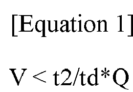
- In Equation 1, the unit of the capacity of the static mixer may be ml, the unit of the injection amount (Q) may be ml, and the unit of the process unit time (td) and the time (t2) during which the initial mixing viscosity is doubled may be min.
- On the other hand, when the capacity (V) of the static mixer is larger than the capacity satisfying Equation 1, the capacity (V) exceeds the usage per unit process, whereby the time during which the heat-dissipating material stays in the static mixer increases, and the process speed is slower or, in severe cases, there is a possibility that the static mixer (100) is clogged.
- On the other hand, the heat-dissipating material relates to a thermally conductive resin composition. The resin composition may comprise a resin component and a thermally conductive filler.
- In one example, the resin composition may be an adhesive composition, for example, a composition capable of forming an adhesive through a curing reaction or the like. Such a resin composition may be a solvent type resin composition, a water-based resin composition, or a solventless-type resin composition. For example, the resin composition may be prepared by compounding a thermally conductive filler, which is described below, to a resin composition capable of forming a known acrylic adhesive, epoxy adhesive, urethane adhesive, olefin adhesive, EVA (ethylene vinyl acetate) adhesive or silicone adhesive.
- The term resin component is generally used as a meaning to include components known as resins as well as components that can be converted into resins through a curing reaction or a polymerization reaction.
- In one example, as the resin component, an adhesive resin or a precursor capable of forming an adhesive resin can be applied. An example of such a resin component includes an acrylic resin, an epoxy resin, a urethane resin, an olefin resin, an EVA (ethylene vinyl acetate) resin or a silicone resin, and the like, or a precursor such as a polyol or an isocyanate compound, and the like, but is not limited thereto.
- The resin composition may comprise a thermally conductive filler together with the resin component. The term thermally conductive filler means a material having a thermal conductivity of about 1 W/mK or more, about 5 W/mK or more, about 10 W/mK or more, or about 15 W/mK or more. The thermal conductivity of the thermally conductive filler may be about 400 W/mK or less, about 350 W/mK or less, or about 300 W/mK or less. The kind of thermally conductive filler is not particularly limited, but ceramic fillers may be applied in consideration of insulation and the like. For example, ceramic particles such as alumina, AlN (aluminum nitride), BN (boron nitride), silicon nitride, SiC or BeO may be used. If insulation properties may be secured, application of carbon fillers such as graphite may also be considered.
- The resin composition may comprise about 600 parts by weight or more of the thermally conductive filler relative to 100 parts by weight of the resin component. In another example, the ratio of the filler may be 650 parts by weight or more, or 700 parts by weight or more, relative to 100 parts by weight of the resin component. The ratio may be about 2,000 parts by weight or less, about 1,500 parts by weight or less, or about 1,100 parts by weight or less, relative to 100 parts by weight of the resin component. Within the ratio range of the filler, it is possible to secure desired physical properties such as thermal conductivity and insulation.
- If the excessive amount of the filler as above is applied for securing the thermal conductivity and the insulation, the viscosity of the resin composition is greatly increased and accordingly, the handling property is lowered, and even after the resin material is formed, it contains bubbles or voids, so that the thermal conductivity may be deteriorated.
- Accordingly, a filler having at least three different diameters may be applied to the resin composition at a predetermined ratio.
- The shape of the filler is not particularly limited, which may be selected in consideration of viscosity and thixotropy of the resin composition, possibility of settling in the composition, the target thermal resistance or thermal conductivity, insulation, a filling effect or dispersibility, and the like. For example, considering the amount to be filled, it is advantageous to use a spherical filler, but in consideration of formation of a network, conductivity, thixotropy and the like, a non-spherical filler, for example, a filler having a shape such as a needle shape or a plate shape can also be used.
- The resin composition basically comprises the above components, that is, the resin component and the thermally conductive filler, and if necessary, it may also comprise other components. For example, the resin composition may further comprise a viscosity control agent, such as a thixotropic agent, a diluent, a dispersant, a surface treatment agent or a coupling agent, for control of viscosity, for example, for increasing or decreasing viscosity, or for control of viscosity according to shear force.
- The thixotropic agent can control the viscosity according to the shear force of the resin composition so that the manufacturing process of the battery module can be effectively performed. The usable thixotropic agent can be exemplified by fumed silica and the like.
- The diluent or dispersant is usually used for lowering the viscosity of the resin composition, and any of various kinds known in the art can be used without limitation as long as it can exhibit the above action.
- The surface treating agent is used for surface treatment of the filler introduced into the resin composition, and any of various kinds known in the art can be used without limitation as long as it can exhibit the above action.
- The coupling agent may be used, for example, to improve the dispersibility of the thermally conductive filler such as alumina, and any of various kinds known in the art may be used without limitation as long as it can exhibit the above action.
- The resin composition may further comprise a flame retardant or a flame retardant auxiliary agent, and the like. Such a resin composition can form a flame retardant resin composition. As the flame retardant, various known flame retardants can be applied without particular limitation, and for example, a solid filler-shaped flame retardant or a liquid flame retardant, and the like can be applied. The flame retardant includes, for example, an organic flame retardant such as melamine cyanurate, or an inorganic flame retardant such as magnesium hydroxide, and the like, but is not limited thereto.
- When the amount of the filler to be filled in the resin composition is large, a liquid type flame retardant material (TEP, triethyl phosphate or TCPP, tris(1,3-chloro-2-propyl) phosphate, etc.) may also be used. Furthermore, a silane coupling agent capable of acting as a flame retardant synergist may also be added.
- The heat-dissipating material may be a heat-dissipating filler high-viscosity two-component room-temperature curing urethane. Also, the heat-dissipating material may have a thermal conductivity of 1.0 W/mK or more, and the heat-dissipating material may have a viscosity of 10 to 300,000 cP. Furthermore, the specific gravity may be 3 g/cm3, the mixer diameter may be 10mm, and the flow rate may be 0.25cm3/sec.
- In addition, when the viscosity is calculated as 100,000, the Reynolds number (Re) may be 58 and the number of elements may be 12. At this time, the lower the viscosity, the smaller the number of elements required. For example, when the viscosity is 100,000 to 1,000,000, the number of elements may be 12 to 25.
- Also, the time (t2) during which the initial mixing viscosity is doubled may be 1 to 10 minutes, the process unit time (td) may be 3 minutes, and the injection amount (Q) for each static mixer may be 30 ml. At this time, if the time (t2) during which the initial mixing viscosity is doubled is 3 minutes, the static mixer maximum capacity (V) is 30 ml upon calculation by Equation 1.
- The curing speed is set to 100 as a normal curing speed at a target mixing ratio (for example, two-component type 1: 1), where on the basis of this, the speed according to the curing time under the same curing condition can be relativized. Also, as an actual process unit time is compared with a target process time, the processability is classified into "O" if the actual process unit time is equal to or faster than the target process time, and "X" if the actual process unit time is slower than that.
- The processability according to the number of elements, the curing speed, t2, td, Q and V is shown in Table 1 below.
[Table 1] Classification Re Number of Elements Curing Speed t2 (min) Td (min) Q (ml) V (ml) Processability Example 1 58 12 100 3 3 30 20 O Example 2 58 8 75 3 3 30 20 O Example 3 58 4 21 3 3 30 20 O Comparative Example 1 58 30 100 3 3 30 20 X Comparative Example 2 58 12 100 3 3 30 50 X - Through Table 1 above, it can be confirmed that the processability can be ensured by satisfying Equation 1.
- The preferred examples of the present invention as described above are disclosed for exemplary purpose, where those skilled in the art having ordinary knowledge for the present invention can make various corrections, modifications and additions within idea and scope of the present invention, and such a correction, modification and addition should be considered as falling within the scope of the following claims.
- According to the mixing method of the heat-dissipating material related to one example of the present invention, the capacity of the static mixer can be optimized in correspondence with the heat-dissipating material.
Claims (10)
- A method for mixing a heat-dissipating material comprising a room-temperature curing filler with a static mixer,
wherein the method for mixing a heat-dissipating material comprises a step of determining a capacity (V) of the static mixer based on an injection amount (Q) per process unit time, a process unit time (td) and a time (t2) during which the viscosity of the heat-dissipating material flowing out of the static mixer becomes twice the initial mixing viscosity, where when the heat-dissipating material is sequentially injected into first and second external devices with the static mixer, the process unit time is the difference between the time on which the heat-dissipating material starts to be injected into the second external device and the time on which the heat-dissipating material starts to be injected into the first external device. - The method for mixing a heat-dissipating material according to claim 1,
wherein the capacity of the static mixer (V) is determined by Equation 1 below:
- The method for mixing a heat-dissipating material according to claim 1,
further comprising a step of performing mixing of the heat-dissipating material at a Reynolds number (Re) of 10 to 1000. - The method for mixing a heat-dissipating material according to claim 1,
wherein the static mixer has a number of elements of 5 to 25. - The method for mixing a heat-dissipating material according to claim 1,
wherein the time (t2) during which the initial mixing viscosity is doubled is 1 to 10 minutes. - The method for mixing a heat-dissipating material according to claim 1,
wherein the heat-dissipating material has a thermal conductivity of 1.0 W/mK or more. - The method for mixing a heat-dissipating material according to claim 1,
wherein the heat-dissipating material has a viscosity of 10 to 300,000 cP. - The method for mixing a heat-dissipating material according to claim 1,
wherein the first and second external devices are each a battery module. - The method for mixing a heat-dissipating material according to claim 1,
wherein when the heat-dissipating material is injected into the first external device with a plurality of static mixers, the capacity of each static mixer is determined based on the injection amount (Q) per process unit time for each static mixer, the process unit time (td) and the time (t2) during which the viscosity of the heat-dissipating material flowing out of the static mixer becomes twice the initial mixing viscosity. - The method for mixing a heat-dissipating material according to claim 9,
wherein when the heat-dissipating material is injected with a plurality of static mixers, the respective static mixers are determined to have the same capacity.
Applications Claiming Priority (2)
| Application Number | Priority Date | Filing Date | Title |
|---|---|---|---|
| KR20170105933 | 2017-08-22 | ||
| PCT/KR2018/009641 WO2019039855A2 (en) | 2017-08-22 | 2018-08-22 | Method for mixing heat dissipation material components |
Publications (3)
| Publication Number | Publication Date |
|---|---|
| EP3662992A2 true EP3662992A2 (en) | 2020-06-10 |
| EP3662992A4 EP3662992A4 (en) | 2020-08-12 |
| EP3662992B1 EP3662992B1 (en) | 2022-08-10 |
Family
ID=65760412
Family Applications (1)
| Application Number | Title | Priority Date | Filing Date |
|---|---|---|---|
| EP18847588.3A Active EP3662992B1 (en) | 2017-08-22 | 2018-08-22 | Method for mixing components of a heat dissipation material |
Country Status (5)
| Country | Link |
|---|---|
| US (1) | US11185832B2 (en) |
| EP (1) | EP3662992B1 (en) |
| JP (1) | JP6973875B2 (en) |
| KR (1) | KR102191612B1 (en) |
| CN (1) | CN111050896B (en) |
Cited By (1)
| Publication number | Priority date | Publication date | Assignee | Title |
|---|---|---|---|---|
| EP3663582A4 (en) * | 2017-08-22 | 2020-08-26 | LG Chem, Ltd. | METHOD OF DETERMINING A DEVICE FOR DISPENSING HEAT DUCTING MATERIAL |
Families Citing this family (8)
| Publication number | Priority date | Publication date | Assignee | Title |
|---|---|---|---|---|
| DE102019207357A1 (en) * | 2019-05-20 | 2020-11-26 | Audi Ag | Method for introducing a heat transfer agent between a battery module and a cooling floor, injection system and battery module |
| DE102019207356A1 (en) * | 2019-05-20 | 2020-11-26 | Audi Ag | Module housing, battery module, high-voltage battery, motor vehicle and method for introducing a heat-conducting medium between a battery module and a cooling floor |
| EP4006090A4 (en) * | 2019-08-19 | 2022-09-07 | LG Chem, Ltd. | RESIN COMPOSITION |
| EP4006089A4 (en) * | 2019-08-19 | 2022-08-31 | LG Chem, Ltd. | Resin composition |
| KR20210029939A (en) * | 2019-09-09 | 2021-03-17 | 주식회사 엘지화학 | Injection Device of Two-component Resin Composition |
| KR20210029938A (en) * | 2019-09-09 | 2021-03-17 | 주식회사 엘지화학 | Injection Device of Resin Composition |
| KR20220119031A (en) | 2019-12-19 | 2022-08-26 | 헨켈 아게 운트 코. 카게아아 | Silicone Free Thermal Interface Material with Reactive Diluent |
| WO2025143811A1 (en) * | 2023-12-26 | 2025-07-03 | 주식회사 엘지에너지솔루션 | Resin composition applicator and battery assembly |
Family Cites Families (20)
| Publication number | Priority date | Publication date | Assignee | Title |
|---|---|---|---|---|
| JP3352564B2 (en) * | 1994-05-20 | 2002-12-03 | ヴィエルティー コーポレーション | Filling method of filling material into assembly |
| US6769220B2 (en) * | 1996-02-08 | 2004-08-03 | Charles E. Friesner | Structural member |
| US20030171487A1 (en) * | 2002-03-11 | 2003-09-11 | Tyco Electronics Corporation | Curable silicone gum thermal interface material |
| US7208192B2 (en) * | 2002-05-31 | 2007-04-24 | Parker-Hannifin Corporation | Thermally or electrically-conductive form-in-place gap filter |
| US7044340B1 (en) * | 2002-06-28 | 2006-05-16 | Mcclellan Luther W | Apparatus and method for optimally mixing and applying a two part epoxy |
| JP2004277477A (en) * | 2003-03-13 | 2004-10-07 | Hiroshi Okai | Method for producing resin cured product |
| DE102004008755A1 (en) * | 2004-02-23 | 2005-09-08 | Hilti Ag | Static mixer and its use |
| JP2009013415A (en) | 2004-03-11 | 2009-01-22 | Hiroshi Okai | Method for producing reactive hot-melt curable composition and coater |
| JP4728731B2 (en) * | 2005-08-01 | 2011-07-20 | 株式会社Gns | Supply method of two-component curable material |
| CN101168121A (en) * | 2006-10-25 | 2008-04-30 | 韩毅军 | Non-propelling mixer |
| CN104249860B (en) | 2006-12-15 | 2017-04-12 | 3M创新有限公司 | Mixing and dispensing curable multi-component materials |
| CN101693175B (en) * | 2009-09-22 | 2011-11-30 | 中材科技风电叶片股份有限公司 | Bi-component rubber-mixing machine and closed-loop control method for rubber mixing thereof |
| JP5422802B2 (en) * | 2010-03-18 | 2014-02-19 | 洋 岡井 | Coating device for two-component mixed fast-curing composition and fast-curing composition |
| JP2014076406A (en) * | 2012-10-09 | 2014-05-01 | Hiroshi Okai | Device for integrally manufacturing and coating thermoplastic polymer |
| WO2015093611A1 (en) | 2013-12-20 | 2015-06-25 | 株式会社堀場エステック | Continuous reaction device and continuous polymerization method using same |
| KR101941117B1 (en) | 2015-02-27 | 2019-01-23 | 주식회사 엘지화학 | Battery module |
| JP6421256B2 (en) | 2015-06-12 | 2018-11-07 | エルジー・ケム・リミテッド | Battery module |
| WO2019039855A2 (en) * | 2017-08-22 | 2019-02-28 | 주식회사 엘지화학 | Method for mixing heat dissipation material components |
| EP3663582B1 (en) * | 2017-08-22 | 2022-04-06 | LG Chem, Ltd. | Method for determining the suitability of an apparatus for dispensing a heat-dissipating material |
| US11041103B2 (en) * | 2017-09-08 | 2021-06-22 | Honeywell International Inc. | Silicone-free thermal gel |
-
2018
- 2018-08-22 JP JP2020531409A patent/JP6973875B2/en active Active
- 2018-08-22 EP EP18847588.3A patent/EP3662992B1/en active Active
- 2018-08-22 US US16/639,990 patent/US11185832B2/en active Active
- 2018-08-22 KR KR1020180097733A patent/KR102191612B1/en active Active
- 2018-08-22 CN CN201880053603.4A patent/CN111050896B/en active Active
Cited By (2)
| Publication number | Priority date | Publication date | Assignee | Title |
|---|---|---|---|---|
| EP3663582A4 (en) * | 2017-08-22 | 2020-08-26 | LG Chem, Ltd. | METHOD OF DETERMINING A DEVICE FOR DISPENSING HEAT DUCTING MATERIAL |
| US11598325B2 (en) | 2017-08-22 | 2023-03-07 | Lg Chem, Ltd. | Method for determining dispensing apparatus for heat-dissipating material |
Also Published As
| Publication number | Publication date |
|---|---|
| US11185832B2 (en) | 2021-11-30 |
| CN111050896A (en) | 2020-04-21 |
| EP3662992A4 (en) | 2020-08-12 |
| CN111050896B (en) | 2022-03-11 |
| KR102191612B1 (en) | 2020-12-15 |
| JP6973875B2 (en) | 2021-12-01 |
| JP2020531279A (en) | 2020-11-05 |
| US20200197888A1 (en) | 2020-06-25 |
| EP3662992B1 (en) | 2022-08-10 |
| KR20190021181A (en) | 2019-03-05 |
Similar Documents
| Publication | Publication Date | Title |
|---|---|---|
| EP3662992B1 (en) | Method for mixing components of a heat dissipation material | |
| EP3264492B1 (en) | Battery module | |
| CN101809734B (en) | Thermally conductive sheet, manufacturing method thereof, and power module | |
| KR102166470B1 (en) | Resin Composition | |
| US8119191B2 (en) | Dispensable cured resin | |
| US20160115343A1 (en) | Thermosetting resin composition, method of producing thermal conductive sheet, and power module | |
| EP3300164A1 (en) | Battery module | |
| US11598325B2 (en) | Method for determining dispensing apparatus for heat-dissipating material | |
| EP1509951A1 (en) | Thermally or electrically conductive gap filler | |
| EP1999529B1 (en) | Dispensable cured resin | |
| US10177068B2 (en) | Heat conductive insulating sheet, power module, and manufacturing method thereof | |
| KR20150073950A (en) | Semiconductor device | |
| KR102391491B1 (en) | Curable Composition | |
| WO2019039855A2 (en) | Method for mixing heat dissipation material components | |
| CN111777985A (en) | Pouring sealant and heat dissipation device | |
| KR100312237B1 (en) | Electronic device modules using a thermally conductive compliant sheet | |
| CN102985510B (en) | Completely crued heat or electricity-conductivity original place form gap-filler | |
| KR20260006336A (en) | Battery including potting compound and manufacturing method thereof | |
| WO2019039852A1 (en) | Method for determining heat dissipation material dispensing device | |
| CN102985510A (en) | Fully-cured thermally or electrically-conductive form-in-place gap filler |
Legal Events
| Date | Code | Title | Description |
|---|---|---|---|
| STAA | Information on the status of an ep patent application or granted ep patent |
Free format text: STATUS: THE INTERNATIONAL PUBLICATION HAS BEEN MADE |
|
| PUAI | Public reference made under article 153(3) epc to a published international application that has entered the european phase |
Free format text: ORIGINAL CODE: 0009012 |
|
| STAA | Information on the status of an ep patent application or granted ep patent |
Free format text: STATUS: REQUEST FOR EXAMINATION WAS MADE |
|
| 17P | Request for examination filed |
Effective date: 20200302 |
|
| AK | Designated contracting states |
Kind code of ref document: A2 Designated state(s): AL AT BE BG CH CY CZ DE DK EE ES FI FR GB GR HR HU IE IS IT LI LT LU LV MC MK MT NL NO PL PT RO RS SE SI SK SM TR |
|
| AX | Request for extension of the european patent |
Extension state: BA ME |
|
| A4 | Supplementary search report drawn up and despatched |
Effective date: 20200713 |
|
| RIC1 | Information provided on ipc code assigned before grant |
Ipc: B29B 7/72 20060101AFI20200707BHEP Ipc: C09J 11/04 20060101ALI20200707BHEP Ipc: B29B 7/90 20060101ALI20200707BHEP Ipc: B29B 7/32 20060101ALI20200707BHEP |
|
| DAV | Request for validation of the european patent (deleted) | ||
| DAX | Request for extension of the european patent (deleted) | ||
| STAA | Information on the status of an ep patent application or granted ep patent |
Free format text: STATUS: EXAMINATION IS IN PROGRESS |
|
| 17Q | First examination report despatched |
Effective date: 20210512 |
|
| REG | Reference to a national code |
Ref country code: DE Ref legal event code: R079 Ref document number: 602018039223 Country of ref document: DE Free format text: PREVIOUS MAIN CLASS: B01F0015000000 Ipc: B29B0007720000 |
|
| GRAP | Despatch of communication of intention to grant a patent |
Free format text: ORIGINAL CODE: EPIDOSNIGR1 |
|
| STAA | Information on the status of an ep patent application or granted ep patent |
Free format text: STATUS: GRANT OF PATENT IS INTENDED |
|
| RIC1 | Information provided on ipc code assigned before grant |
Ipc: B29B 7/90 20060101ALI20220221BHEP Ipc: B29B 7/32 20060101ALI20220221BHEP Ipc: B29B 7/72 20060101AFI20220221BHEP |
|
| INTG | Intention to grant announced |
Effective date: 20220309 |
|
| GRAS | Grant fee paid |
Free format text: ORIGINAL CODE: EPIDOSNIGR3 |
|
| GRAA | (expected) grant |
Free format text: ORIGINAL CODE: 0009210 |
|
| STAA | Information on the status of an ep patent application or granted ep patent |
Free format text: STATUS: THE PATENT HAS BEEN GRANTED |
|
| AK | Designated contracting states |
Kind code of ref document: B1 Designated state(s): AL AT BE BG CH CY CZ DE DK EE ES FI FR GB GR HR HU IE IS IT LI LT LU LV MC MK MT NL NO PL PT RO RS SE SI SK SM TR |
|
| REG | Reference to a national code |
Ref country code: AT Ref legal event code: REF Ref document number: 1510166 Country of ref document: AT Kind code of ref document: T Effective date: 20220815 Ref country code: CH Ref legal event code: EP |
|
| REG | Reference to a national code |
Ref country code: IE Ref legal event code: FG4D |
|
| REG | Reference to a national code |
Ref country code: DE Ref legal event code: R096 Ref document number: 602018039223 Country of ref document: DE |
|
| REG | Reference to a national code |
Ref country code: NL Ref legal event code: MP Effective date: 20220810 |
|
| REG | Reference to a national code |
Ref country code: LT Ref legal event code: MG9D |
|
| PG25 | Lapsed in a contracting state [announced via postgrant information from national office to epo] |
Ref country code: SE Free format text: LAPSE BECAUSE OF FAILURE TO SUBMIT A TRANSLATION OF THE DESCRIPTION OR TO PAY THE FEE WITHIN THE PRESCRIBED TIME-LIMIT Effective date: 20220810 Ref country code: RS Free format text: LAPSE BECAUSE OF FAILURE TO SUBMIT A TRANSLATION OF THE DESCRIPTION OR TO PAY THE FEE WITHIN THE PRESCRIBED TIME-LIMIT Effective date: 20220810 Ref country code: PT Free format text: LAPSE BECAUSE OF FAILURE TO SUBMIT A TRANSLATION OF THE DESCRIPTION OR TO PAY THE FEE WITHIN THE PRESCRIBED TIME-LIMIT Effective date: 20221212 Ref country code: NO Free format text: LAPSE BECAUSE OF FAILURE TO SUBMIT A TRANSLATION OF THE DESCRIPTION OR TO PAY THE FEE WITHIN THE PRESCRIBED TIME-LIMIT Effective date: 20221110 Ref country code: NL Free format text: LAPSE BECAUSE OF FAILURE TO SUBMIT A TRANSLATION OF THE DESCRIPTION OR TO PAY THE FEE WITHIN THE PRESCRIBED TIME-LIMIT Effective date: 20220810 Ref country code: LV Free format text: LAPSE BECAUSE OF FAILURE TO SUBMIT A TRANSLATION OF THE DESCRIPTION OR TO PAY THE FEE WITHIN THE PRESCRIBED TIME-LIMIT Effective date: 20220810 Ref country code: LT Free format text: LAPSE BECAUSE OF FAILURE TO SUBMIT A TRANSLATION OF THE DESCRIPTION OR TO PAY THE FEE WITHIN THE PRESCRIBED TIME-LIMIT Effective date: 20220810 Ref country code: FI Free format text: LAPSE BECAUSE OF FAILURE TO SUBMIT A TRANSLATION OF THE DESCRIPTION OR TO PAY THE FEE WITHIN THE PRESCRIBED TIME-LIMIT Effective date: 20220810 |
|
| REG | Reference to a national code |
Ref country code: AT Ref legal event code: MK05 Ref document number: 1510166 Country of ref document: AT Kind code of ref document: T Effective date: 20220810 |
|
| PG25 | Lapsed in a contracting state [announced via postgrant information from national office to epo] |
Ref country code: PL Free format text: LAPSE BECAUSE OF FAILURE TO SUBMIT A TRANSLATION OF THE DESCRIPTION OR TO PAY THE FEE WITHIN THE PRESCRIBED TIME-LIMIT Effective date: 20220810 Ref country code: IS Free format text: LAPSE BECAUSE OF FAILURE TO SUBMIT A TRANSLATION OF THE DESCRIPTION OR TO PAY THE FEE WITHIN THE PRESCRIBED TIME-LIMIT Effective date: 20221210 Ref country code: HR Free format text: LAPSE BECAUSE OF FAILURE TO SUBMIT A TRANSLATION OF THE DESCRIPTION OR TO PAY THE FEE WITHIN THE PRESCRIBED TIME-LIMIT Effective date: 20220810 Ref country code: GR Free format text: LAPSE BECAUSE OF FAILURE TO SUBMIT A TRANSLATION OF THE DESCRIPTION OR TO PAY THE FEE WITHIN THE PRESCRIBED TIME-LIMIT Effective date: 20221111 |
|
| REG | Reference to a national code |
Ref country code: CH Ref legal event code: PL |
|
| PG25 | Lapsed in a contracting state [announced via postgrant information from national office to epo] |
Ref country code: SM Free format text: LAPSE BECAUSE OF FAILURE TO SUBMIT A TRANSLATION OF THE DESCRIPTION OR TO PAY THE FEE WITHIN THE PRESCRIBED TIME-LIMIT Effective date: 20220810 Ref country code: RO Free format text: LAPSE BECAUSE OF FAILURE TO SUBMIT A TRANSLATION OF THE DESCRIPTION OR TO PAY THE FEE WITHIN THE PRESCRIBED TIME-LIMIT Effective date: 20220810 Ref country code: LU Free format text: LAPSE BECAUSE OF NON-PAYMENT OF DUE FEES Effective date: 20220822 Ref country code: LI Free format text: LAPSE BECAUSE OF NON-PAYMENT OF DUE FEES Effective date: 20220831 Ref country code: ES Free format text: LAPSE BECAUSE OF FAILURE TO SUBMIT A TRANSLATION OF THE DESCRIPTION OR TO PAY THE FEE WITHIN THE PRESCRIBED TIME-LIMIT Effective date: 20220810 Ref country code: DK Free format text: LAPSE BECAUSE OF FAILURE TO SUBMIT A TRANSLATION OF THE DESCRIPTION OR TO PAY THE FEE WITHIN THE PRESCRIBED TIME-LIMIT Effective date: 20220810 Ref country code: CZ Free format text: LAPSE BECAUSE OF FAILURE TO SUBMIT A TRANSLATION OF THE DESCRIPTION OR TO PAY THE FEE WITHIN THE PRESCRIBED TIME-LIMIT Effective date: 20220810 Ref country code: CH Free format text: LAPSE BECAUSE OF NON-PAYMENT OF DUE FEES Effective date: 20220831 Ref country code: AT Free format text: LAPSE BECAUSE OF FAILURE TO SUBMIT A TRANSLATION OF THE DESCRIPTION OR TO PAY THE FEE WITHIN THE PRESCRIBED TIME-LIMIT Effective date: 20220810 |
|
| REG | Reference to a national code |
Ref country code: BE Ref legal event code: MM Effective date: 20220831 |
|
| REG | Reference to a national code |
Ref country code: DE Ref legal event code: R097 Ref document number: 602018039223 Country of ref document: DE |
|
| PG25 | Lapsed in a contracting state [announced via postgrant information from national office to epo] |
Ref country code: SK Free format text: LAPSE BECAUSE OF FAILURE TO SUBMIT A TRANSLATION OF THE DESCRIPTION OR TO PAY THE FEE WITHIN THE PRESCRIBED TIME-LIMIT Effective date: 20220810 Ref country code: MC Free format text: LAPSE BECAUSE OF FAILURE TO SUBMIT A TRANSLATION OF THE DESCRIPTION OR TO PAY THE FEE WITHIN THE PRESCRIBED TIME-LIMIT Effective date: 20220810 Ref country code: EE Free format text: LAPSE BECAUSE OF FAILURE TO SUBMIT A TRANSLATION OF THE DESCRIPTION OR TO PAY THE FEE WITHIN THE PRESCRIBED TIME-LIMIT Effective date: 20220810 |
|
| PLBE | No opposition filed within time limit |
Free format text: ORIGINAL CODE: 0009261 |
|
| STAA | Information on the status of an ep patent application or granted ep patent |
Free format text: STATUS: NO OPPOSITION FILED WITHIN TIME LIMIT |
|
| PG25 | Lapsed in a contracting state [announced via postgrant information from national office to epo] |
Ref country code: AL Free format text: LAPSE BECAUSE OF FAILURE TO SUBMIT A TRANSLATION OF THE DESCRIPTION OR TO PAY THE FEE WITHIN THE PRESCRIBED TIME-LIMIT Effective date: 20220810 |
|
| 26N | No opposition filed |
Effective date: 20230511 |
|
| PG25 | Lapsed in a contracting state [announced via postgrant information from national office to epo] |
Ref country code: IE Free format text: LAPSE BECAUSE OF NON-PAYMENT OF DUE FEES Effective date: 20220822 |
|
| PG25 | Lapsed in a contracting state [announced via postgrant information from national office to epo] |
Ref country code: SI Free format text: LAPSE BECAUSE OF FAILURE TO SUBMIT A TRANSLATION OF THE DESCRIPTION OR TO PAY THE FEE WITHIN THE PRESCRIBED TIME-LIMIT Effective date: 20220810 |
|
| PG25 | Lapsed in a contracting state [announced via postgrant information from national office to epo] |
Ref country code: BE Free format text: LAPSE BECAUSE OF NON-PAYMENT OF DUE FEES Effective date: 20220831 |
|
| PG25 | Lapsed in a contracting state [announced via postgrant information from national office to epo] |
Ref country code: CY Free format text: LAPSE BECAUSE OF FAILURE TO SUBMIT A TRANSLATION OF THE DESCRIPTION OR TO PAY THE FEE WITHIN THE PRESCRIBED TIME-LIMIT Effective date: 20220810 |
|
| PG25 | Lapsed in a contracting state [announced via postgrant information from national office to epo] |
Ref country code: MK Free format text: LAPSE BECAUSE OF FAILURE TO SUBMIT A TRANSLATION OF THE DESCRIPTION OR TO PAY THE FEE WITHIN THE PRESCRIBED TIME-LIMIT Effective date: 20220810 Ref country code: IT Free format text: LAPSE BECAUSE OF FAILURE TO SUBMIT A TRANSLATION OF THE DESCRIPTION OR TO PAY THE FEE WITHIN THE PRESCRIBED TIME-LIMIT Effective date: 20220810 Ref country code: HU Free format text: LAPSE BECAUSE OF FAILURE TO SUBMIT A TRANSLATION OF THE DESCRIPTION OR TO PAY THE FEE WITHIN THE PRESCRIBED TIME-LIMIT; INVALID AB INITIO Effective date: 20180822 |
|
| PG25 | Lapsed in a contracting state [announced via postgrant information from national office to epo] |
Ref country code: BG Free format text: LAPSE BECAUSE OF FAILURE TO SUBMIT A TRANSLATION OF THE DESCRIPTION OR TO PAY THE FEE WITHIN THE PRESCRIBED TIME-LIMIT Effective date: 20220810 |
|
| PG25 | Lapsed in a contracting state [announced via postgrant information from national office to epo] |
Ref country code: MT Free format text: LAPSE BECAUSE OF FAILURE TO SUBMIT A TRANSLATION OF THE DESCRIPTION OR TO PAY THE FEE WITHIN THE PRESCRIBED TIME-LIMIT Effective date: 20220810 |
|
| PGFP | Annual fee paid to national office [announced via postgrant information from national office to epo] |
Ref country code: DE Payment date: 20250721 Year of fee payment: 8 |
|
| PGFP | Annual fee paid to national office [announced via postgrant information from national office to epo] |
Ref country code: GB Payment date: 20250722 Year of fee payment: 8 |
|
| PGFP | Annual fee paid to national office [announced via postgrant information from national office to epo] |
Ref country code: FR Payment date: 20250725 Year of fee payment: 8 |
|
| PG25 | Lapsed in a contracting state [announced via postgrant information from national office to epo] |
Ref country code: TR Free format text: LAPSE BECAUSE OF FAILURE TO SUBMIT A TRANSLATION OF THE DESCRIPTION OR TO PAY THE FEE WITHIN THE PRESCRIBED TIME-LIMIT Effective date: 20220810 |